A technique for mitigating the effect of the writing-beam profile on fibre Bragg grating fabrication Elena G. Turitsyna, * Adenowo Gbadebo, and John A. R. Williams Aston Institute of Photonic Technologies, Aston University, Aston Triangle, Birmingham B4 7ET, UK * [email protected] Abstract: We propose and demonstrate a pre-compensation mechanism to account for the writing-beam profile which when applied to the design of advanced fibre Bragg gratings helps to achieve a desired design spectral response. We use the example of a complex multi-channel grating as an example to demonstrate the improvement achievable using the pre- compensation and find good agreement between experimental results and numerical calculations. © 2015 Optical Society of America OCIS codes: (060.3735) Fiber Bragg gratings; (060.2300) Fiber measurements. References and links 1. F. Ouellette, “Dispersion cancellation using linearly chirped Bragg grating filters in optical waveguides,” Opt. Lett. 12(10), 847–849 (1987). 2. X. Shu, S. Jiang, and D. Huang, “Fiber grating Sagnac loop and its multiwavelength laser application,” IEEE Photon. Technol. Lett. 12, 980–982 (2000). 3. J. Bland-Hawthorn, A. Buryak, and K. Kolossovski, “Optimization algorithm for ultrabroadband multichannel aperiodic fiber Bragg grating filters,” J. Opt. Soc. Am. A 25(1), 153–158 (2008). 4. J. Skaar and T. Erdogan, “On the synthesis of fiber Bragg gratings by layer peeling,” IEEE J. Quantum Electron. 37(2), 165–173 (2001). 5. Y. Dai and J. P. Yao, “Multi-channel Bragg gratings, Opt. Express 16(15), 11216–11223 (2008). 6. X. Chen, J. Hayashi, and H. Li, “Simultaneous dispersion and dispersion-slope compensator based on a doubly sampled ultrahigh-channel-count fiber Bragg grating,” Appl. Opt. 49(5), 823–828 (2010). 7. H. Li, M. Li, Y. Sheng, and J. E. Rothenberg, “Advances in the design and fabrication of high-channel-count fiber Bragg gratings,” J. Lightwave Technol. 25(9), 2739–2750 (2007). 8. R. Kashyap, Fiber Bragg Gratings (Academic, 1999). 9. A. V. Buryak, K. Y. Kolossovski, and D. Y. Stepanov, “Optimization of refractive index sampling for multichannel fiber Bragg gratings,” IEEE J. Quantum Electron. 39(1), 91–98 (2003). 10. M. J. Cole, W. H. Loh, R. I. Laming, M. N. Zervas, and S. Barcelos, “Moving fibre/phase mask-scanning beam technique for enhanced flexibility in producing fibre gratings with uniform phase mask,” Electron. Lett. 31(17), 1488–1489 (1995). 11. W. H. Loh, M. J. Cole, M. N. Zervas, S. Barcelos, and R. I. Laming, “Complex grating structures with uniform phase masks based on the moving fiber-scanning beam technique,” Opt. Lett. 20, 2051–2053 (1995). 12. M. Li and H. Li, “Influences of writing-beam size on the performances of dispersion-free multi-channel fiber Bragg grating,” Opt. Fiber Technol. 15(1), 33–38 (2009). 13. H. Cao, J. Atai, X. Shu, and G. Chen, “Direct design of high channel-count fiber Bragg grating filters with low index modulation,” Opt. Express 20(11), 12095–12110 (2012). 14. J. Williams, “Method of fabricating an optical waveguide grating and apparatus for implementing the method,” U.S. Patent EP1447691A1 (August 18, 2004). #236033 - $15.00 USD Received 11 Mar 2015; revised 28 Apr 2015; accepted 29 Apr 2015; published 5 May 2015 (C) 2015 OSA 18 May 2015 | Vol. 23, No. 10 | DOI:10.1364/OE.23.012628 | OPTICS EXPRESS 12628

Welcome message from author
This document is posted to help you gain knowledge. Please leave a comment to let me know what you think about it! Share it to your friends and learn new things together.
Transcript

A technique for mitigating the effect ofthe writing-beam profile on fibre Bragg
grating fabrication
Elena G. Turitsyna,∗ Adenowo Gbadebo, and John A. R. WilliamsAston Institute of Photonic Technologies, Aston University, Aston Triangle,
Birmingham B4 7ET, UK∗[email protected]
Abstract: We propose and demonstrate a pre-compensation mechanismto account for the writing-beam profile which when applied to the designof advanced fibre Bragg gratings helps to achieve a desired design spectralresponse. We use the example of a complex multi-channel grating asan example to demonstrate the improvement achievable using the pre-compensation and find good agreement between experimental results andnumerical calculations.
© 2015 Optical Society of America
OCIS codes: (060.3735) Fiber Bragg gratings; (060.2300) Fiber measurements.
References and links1. F. Ouellette, “Dispersion cancellation using linearly chirped Bragg grating filters in optical waveguides,” Opt.
Lett. 12(10), 847–849 (1987).2. X. Shu, S. Jiang, and D. Huang, “Fiber grating Sagnac loop and its multiwavelength laser application,” IEEE
Photon. Technol. Lett. 12, 980–982 (2000).3. J. Bland-Hawthorn, A. Buryak, and K. Kolossovski, “Optimization algorithm for ultrabroadband multichannel
aperiodic fiber Bragg grating filters,” J. Opt. Soc. Am. A 25(1), 153–158 (2008).4. J. Skaar and T. Erdogan, “On the synthesis of fiber Bragg gratings by layer peeling,” IEEE J. Quantum Electron.
37(2), 165–173 (2001).5. Y. Dai and J. P. Yao, “Multi-channel Bragg gratings, Opt. Express 16(15), 11216–11223 (2008).6. X. Chen, J. Hayashi, and H. Li, “Simultaneous dispersion and dispersion-slope compensator based on a doubly
sampled ultrahigh-channel-count fiber Bragg grating,” Appl. Opt. 49(5), 823–828 (2010).7. H. Li, M. Li, Y. Sheng, and J. E. Rothenberg, “Advances in the design and fabrication of high-channel-count fiber
Bragg gratings,” J. Lightwave Technol. 25(9), 2739–2750 (2007).8. R. Kashyap, Fiber Bragg Gratings (Academic, 1999).9. A. V. Buryak, K. Y. Kolossovski, and D. Y. Stepanov, “Optimization of refractive index sampling for multichannel
fiber Bragg gratings,” IEEE J. Quantum Electron. 39(1), 91–98 (2003).10. M. J. Cole, W. H. Loh, R. I. Laming, M. N. Zervas, and S. Barcelos, “Moving fibre/phase mask-scanning beam
technique for enhanced flexibility in producing fibre gratings with uniform phase mask,” Electron. Lett. 31(17),1488–1489 (1995).
11. W. H. Loh, M. J. Cole, M. N. Zervas, S. Barcelos, and R. I. Laming, “Complex grating structures with uniformphase masks based on the moving fiber-scanning beam technique,” Opt. Lett. 20, 2051–2053 (1995).
12. M. Li and H. Li, “Influences of writing-beam size on the performances of dispersion-free multi-channel fiberBragg grating,” Opt. Fiber Technol. 15(1), 33–38 (2009).
13. H. Cao, J. Atai, X. Shu, and G. Chen, “Direct design of high channel-count fiber Bragg grating filters with lowindex modulation,” Opt. Express 20(11), 12095–12110 (2012).
14. J. Williams, “Method of fabricating an optical waveguide grating and apparatus for implementing the method,”U.S. Patent EP1447691A1 (August 18, 2004).
#236033 - $15.00 USD Received 11 Mar 2015; revised 28 Apr 2015; accepted 29 Apr 2015; published 5 May 2015 (C) 2015 OSA 18 May 2015 | Vol. 23, No. 10 | DOI:10.1364/OE.23.012628 | OPTICS EXPRESS 12628

1. Introduction
Advanced multi-channel fibre Bragg gratings (FBG) are receiving much attention recently withapplications in WDM (wave division multiplexing) telecommunication systems [1], multi-wavelength fibre lasers [2], and astrophotonics [3]. Demands for larger channel counts anddispersion control across the channels increases the complexity of the designed FBGs and thechallenges of fabricating them.
There have been many different methods for designing multichannel gratings investigatedover the past decade. Examples include the inverse layer peeling (LP) algorithm [4], samplingmethods (phase only, amplitude only, and phase-amplitude sampling) [5–7], and Moire gratingstructures [8]. The layer peeling algorithm is the most general approach. However as the num-ber of channels increases, the maximum required refractive index modulation of these designsincreases too, such that they become impractical. Combining layer peeling with optimisationmethods one can reduce the required index modulation to a realisable level [9].
A common approach to fabricating complex FBG devices is to use a uniform phase maskand gradually move the writing beam and phase mask relative to the fibre while modulating thebeam to enable apodisation and wavelength and phase shifts in the fabricate device e.g. [10,11].While this approach is flexible, there are limitations, due to the writing beam size, on the rate atwhich the grating phase can vary with distance [10, 12]. Previous work [10] has accounted forthis assuming a rectangular beam profile but there has been little attention on how to redesignthe gratings to mitigate the effect. To overcome this problem, Li and Li in [12] apply pre-compensation to the target reflectivity spectrum and then obtain the coupling coefficient withthe layer peeling algorithm. However, their approach can lead to unphysical pre-compensatedtarget spectra with reflectivities greater than 1.
In this paper we propose and demonstrate a simple mechanism of pre-compensation appliedin the coupling coefficient design process that is more generally applicable and doesn’t leadto unphysical target spectra. It enables a significant improvement in the performance of thefabricated gratings bringing them closer to the target design parameters. The technique uses theexperimentally measured beam profile which may not be rectangular. We use the example ofmultichannel FBG-based comb filters to demonstrate both the effect and its mitigation takingaccount of the measured Gaussian writing beam profile.
2. Design of a multi-channel dispersion free grating
We consider a 13 channel FBG with 0.2 nm bandwidth of each channel and 0.5 nm channel sep-aration designed for application in a mode-locked fibre laser. The target reflectivity is describedby
|r(λ )|=√
0.7513
∑j=1
exp
(−(
λ −λ j
b
)4)× exp
(i2πneff
(1λ− 1
λ j
)d j
)(1)
Here b = 0.2 nm is the bandwidth of each channel, λ j = 1545+ 0.5× j nm is the centralwavelength for channel j , neff the effective refractive index, and d j is a tailored group delayprofile for each channel. The group delay term helps to avoid the concentration of the indexmodulation in the middle of the grating, which would occur if each channel had the identicalgroup delay [9,13]. The central wavelength of the full spectrum is 1550 nm and the total lengthof the grating is 6 cm. Given Eq. (1), the LP algorithm is used to reconstruct the grating structureand obtain the corresponding coupling coefficient q(z). Optimisation of group delay values d jis used to smoothen the grating apodisation profile and to reduce the period change variationand chirp along its length. Figure 1 illustrates the corresponding reconstructed grating in termsof the complex coupling coefficient q(z) and its spectral response. Here z represents the grating
#236033 - $15.00 USD Received 11 Mar 2015; revised 28 Apr 2015; accepted 29 Apr 2015; published 5 May 2015 (C) 2015 OSA 18 May 2015 | Vol. 23, No. 10 | DOI:10.1364/OE.23.012628 | OPTICS EXPRESS 12629

position along the fibre. Using the same approach we also modelled 5, 9, 11 and 13 peakgratings with the same channel separation and channel bandwidth for comparison.
3. Spectral degradation due to the writing beam size
The fabrication of fibre Bragg gratings with complex and precise profiles requires elaborateequipment and a detailed consideration of the constraints and the trade-offs of the fabricationprocess. An ideal fabrication system would be one that can support a wide range of phase andindex modulation change with high precision. Initial demonstrations used phase mask ditheringto perform apodisation and phase change [14]. The approach used here involves micro-stitchingtogether a large number of short homogenous FBGs while moving the fibre continuously in afringe pattern formed by a phase mask. The illuminating UV beam is modulated based on theposition of the fibre and the required apodisation and localised wavelength of the FBG. Themodulation is controlled such that successive FBGs overlay each other coherently. Chirp in thegrating is achieved by allowing a small phase offset between successive exposures. If the overallshift reaches π over the beam width the grating will be erased. Thus the beam size (number offringes) has an impact on the achievable change in wavelength and, at a specific wavelengthoffset, has an affect on the overall grating strength. This is a well known problem previouslydiscussed in [10], where the authors considered a rectangular laser beam profile and made aprediction of the impact of beam size on FBG reflectivity but did not compensate for it as wedo here.
Here we consider a UV writing-beam with a Gaussian beam profile expressed as
b(z) = exp
(−(
zw/2
)2)
(2)
Here z is the position along the fibre and w is the beam width parameter. The index-modulationprofile formed in a fibre core qconv is the result of convolution of the ideal grating q(z) and this
0
200
400
|q(z)|
(m−1)
(a)
0 2 4 60
25
50
Distance (cm)
argq(z)
(2π
)
(b)0
0.2
0.4
0.6
0.8
Refl
ecti
vit
y
(c)
1546 1548 1550 1552 1554−200
0
200
400
600
Wavelength (nm)
Gro
up
Del
ay(p
s) (d)
Fig. 1. A 13 peak FBG design profile: (a) coupling coefficient, (b) grating phase. Resultingcalculated spectral response: (c) reflectivity; (d) group delay.
#236033 - $15.00 USD Received 11 Mar 2015; revised 28 Apr 2015; accepted 29 Apr 2015; published 5 May 2015 (C) 2015 OSA 18 May 2015 | Vol. 23, No. 10 | DOI:10.1364/OE.23.012628 | OPTICS EXPRESS 12630

Gaussian beam b(z).qconv(z) = q(z)∗b(z) (3)
The values of beam width used in the calculations were taken from measurements of thebeam from our Coherent I300 244 nm laser taken using a Thorlabs UV106-UV beam profiler.They are quoted as full width at the 1/e2 level of the measured Gaussian profile.
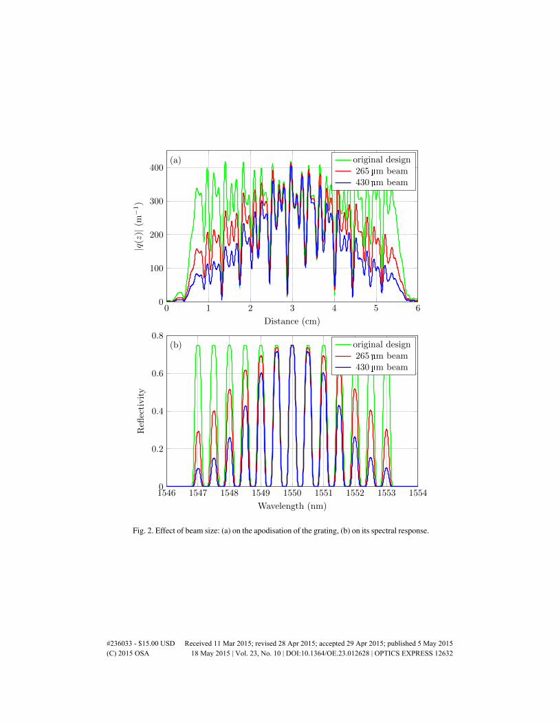
Considering various values for the beam width, we calculated the resulting grating profileand its corresponding spectral response. Figure 2(a) shows the numerically simulated resultingapodisation for the gratings after the convolution with the beams of 265 µm and 430 µm width.The apodisation results in gradually reduced the coupling coefficient at the grating edges. Thephase of the grating wasn’t affected by the convolution and its profile remained the same asshown in Fig. 1(b). These changes in apodisation profile inevitably lead to degradation of theresulting spectral response with increasing beam width (shown in Fig. 2(b)), which was alsoconfirmed experimentally with the results illustrated in Fig. 3.
We compare the spectral response of fabricated 5 and 11 channel gratings with beam sizesof 265 µm and 430 µm. The gratings were fabricated using a computer controller high precisionfabrication setup using a 244 nm frequency doubled CW argon ion laser. A phase mask wasused to produce the fringes, with the wavelength centred at 1550 nm. The fibre was mountedon a high accuracy air-bearing stage and scanned across the incident beam at a constant speed.Numerically modelled coupling coefficients were used for generating their apodisation andchirp that were controlled during fabrication process by an acousto-optic modulator put in thepath of the beam. Varying beam sizes were achieved using focusing optics in the path of thebeam. The exposed fibre was hydrogen loaded. The gratings were measured with an opticalvector analyser with high resolution post annealing at 80◦C for 48 hrs after fabrication.
4. Pre-compensation
There have been a few attempts at solving the problem of adjusting the designed grating profileto reduce the effect of the beam size. Li and Li in [12] apply pre-compensation to the targetreflectivity spectrum and then obtain the coupling coefficient with the layer peeling algorithm.However, their approach can lead to unphysical pre-compensated target spectra with reflectivi-ties greater than 1. The authors showed that even for a beam size as small as 65 µm, they had toreduce the target spectrum reflectivity to 0.75.
Here we propose to apply pre-compensation to the designed “ideal” coupling coefficient. Byperforming the Fourier transform to Eq. (3), we obtain
F (qconv(z)) = F (q(z))F (b(z)) (4)
where F represents the Fourier transform. Now we assume that our ideal coupling coefficientq(z) is the result of convolution of some pre-compensated coupling coefficient qprecomp(z) andthe beam b(z):
q(z) = qprecomp(z)∗b(z). (5)
To retrieve qprecomp(z) from Eq. (5) one has to perform deconvolution via the Fourier and in-verse Fourier transform:
qprecomp(z) = F−1[F (q)/F (b)] (6)
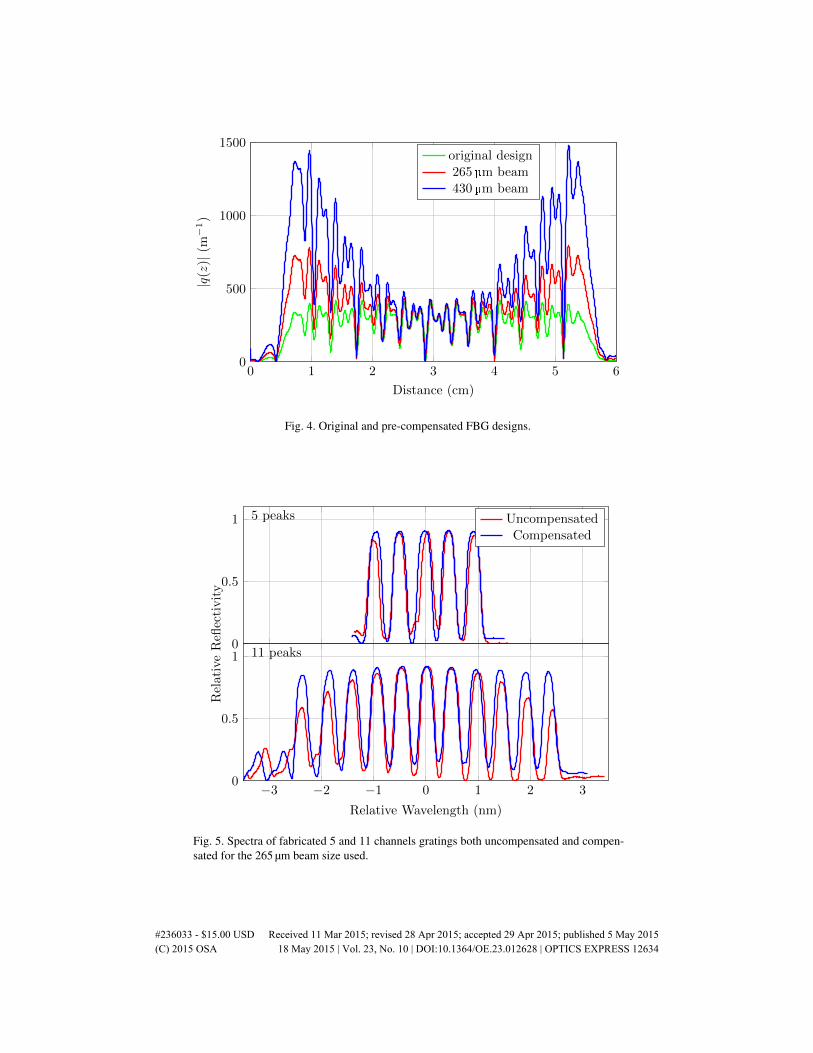
Figure 4 shows the comparison of the apodisation profile of the original grating and numer-ically simulated pre-compensated (using Eq. (6)) gratings for the beam sizes of 265 µm and430 µm. We see the increase in the required index modulation at the edges of the grating. It isalso seen that for a large beam of 430 µm the maximum index modulation is 4.5 times largerthan for smaller beam of 265 µm which makes its fabrication more challenging.
#236033 - $15.00 USD Received 11 Mar 2015; revised 28 Apr 2015; accepted 29 Apr 2015; published 5 May 2015 (C) 2015 OSA 18 May 2015 | Vol. 23, No. 10 | DOI:10.1364/OE.23.012628 | OPTICS EXPRESS 12631
0 1 2 3 4 5 60
100
200
300
400
Distance (cm)
|q(z)|
(m−1)
(a) original design265µm beam430µm beam
1546 1547 1548 1549 1550 1551 1552 1553 15540
0.2
0.4
0.6
0.8
Wavelength (nm)
Refl
ecti
vit
y
(b) original design265µm beam430µm beam
Fig. 2. Effect of beam size: (a) on the apodisation of the grating, (b) on its spectral response.
#236033 - $15.00 USD Received 11 Mar 2015; revised 28 Apr 2015; accepted 29 Apr 2015; published 5 May 2015 (C) 2015 OSA 18 May 2015 | Vol. 23, No. 10 | DOI:10.1364/OE.23.012628 | OPTICS EXPRESS 12632

0
0.5
1 5 peaks 265µm430µm
−3 −2 −1 0 1 2 30
0.5
1
Relative Wavelength (nm)
Rel
ativ
eR
eflec
tivit
y
11 peaks
Fig. 3. Experimental gratings spectra for differing beam widths without compensation.
If we fabricate the grating using the pre-compensated coupling coefficient profile qprecomp(z),we would expect to achieve the target spectrum, because the convolution of the coupling coeffi-cient qprecomp(z) with the beam b(z) will result in the original (ideal) coupling coefficient q(z).The spectra of the experimentally fabricated gratings (Fig. 5) show a significant improvement,compared to the original (without pre-compensation) gratings as shown in Fig. 3.
Figure 6 shows the experimentally measured relative channel positions for fabricated gratingsusing pre-compensated and uncompensated designs and using two different writing beam sizes.The improvement brought about by the pre-compensation can be seen in the flattening of therelative position curves.
5. Discussion
The demonstrated mechanism of pre-compensation uses a very simple and well-known decon-volution principle. One can easily apply such method to some gratings profiles and achieve thetarget design spectrum. It is not very efficient regarding the index modulation contrast, but itdoes offer a solution to the discussed problem for gratings with limited refractive index modu-lations.
The maximum beam width, which may be used to fabricate a given structure, is limited bythe maximum index change available to use in the compensated design. Using a 100 mW Ar+laser and hydrogen loaded standard telecommunications fibre we reliably are able to achievea maximum coupling coefficient of |q(z)| = 2500 m−1. For our 11 and 5 peak compensatedgrating designs the maximum usable beam sizes are 460 µm and 1250 µm respectively. With21 channels, the resulting compensated coupling coefficient becomes larger, and the maximumusable beam size reduces to 350 µm.
The beam size has an impact on the relative positions of the channels of an order of 0.05 nmin addition to their strength (Fig. 6). We suggest, this is due to diffusion of the loaded hydrogenin the fibre, and is the focus of on-going research.
#236033 - $15.00 USD Received 11 Mar 2015; revised 28 Apr 2015; accepted 29 Apr 2015; published 5 May 2015 (C) 2015 OSA 18 May 2015 | Vol. 23, No. 10 | DOI:10.1364/OE.23.012628 | OPTICS EXPRESS 12633
0 1 2 3 4 5 60
500
1000
1500
Distance (cm)
|q(z)|
(m−1)
original design265 µm beam430µm beam
Fig. 4. Original and pre-compensated FBG designs.
0
0.5
1 5 peaks UncompensatedCompensated
−3 −2 −1 0 1 2 30
0.5
1
Relative Wavelength (nm)
Rel
ativ
eR
eflec
tivit
y
11 peaks
Fig. 5. Spectra of fabricated 5 and 11 channels gratings both uncompensated and compen-sated for the 265 µm beam size used.
#236033 - $15.00 USD Received 11 Mar 2015; revised 28 Apr 2015; accepted 29 Apr 2015; published 5 May 2015 (C) 2015 OSA 18 May 2015 | Vol. 23, No. 10 | DOI:10.1364/OE.23.012628 | OPTICS EXPRESS 12634

1549 1550 1551 1552 1553 1554−0.4
−0.2
0
Wavelength (nm)
5 peaks
265C 430C265U 430U
−0.6
−0.4
−0.2
0 9 peaks−0.8
−0.6
−0.4
−0.2
0 11 peaks−0.8
−0.6
−0.4
−0.2
0 13 peaks
Off
set
from
des
ign
pea
kce
ntr
e(n
m)
Fig. 6. Channel positions for fabricated 5, 9, 11 and 13-channels gratings. U stands foruncompensated, C for compensated grating designs, 265 and 430 correspond to the beamsize in µm.
6. Conclusions
In this work we demonstrate a mechanism of pre-compensation of designed fibre Bragg grat-ings in order to reduce the impact of writing beam size on the resulting grating. We apply adeconvolution of the Gaussian profiled writing laser beam to the designed coupling coefficient.Inevitably, it requires larger values of coupling coefficient to compensate for lower coupling co-efficient contrast at the edges. We show that for large beam sizes it is unfeasible to apply enoughpre-compensation to achieve the desired spectral response, whereas for sufficiently small beamsizes this mechanism significantly improves the performance of the resulting grating. Numeri-cal simulations show a good match with experimental results.
#236033 - $15.00 USD Received 11 Mar 2015; revised 28 Apr 2015; accepted 29 Apr 2015; published 5 May 2015 (C) 2015 OSA 18 May 2015 | Vol. 23, No. 10 | DOI:10.1364/OE.23.012628 | OPTICS EXPRESS 12635
Related Documents