Running head: APERTURE-COUPLED ANTENNA TECHNOLOGY 1 A Technical Assessment of Aperture-coupled Antenna Technology Justin Obenchain A Senior Thesis submitted in partial fulfillment of the requirements for graduation in the Honors Program Liberty University Spring 2014

Welcome message from author
This document is posted to help you gain knowledge. Please leave a comment to let me know what you think about it! Share it to your friends and learn new things together.
Transcript

Running head: APERTURE-COUPLED ANTENNA TECHNOLOGY 1
A Technical Assessment of Aperture-coupled Antenna Technology
Justin Obenchain
A Senior Thesis submitted in partial fulfillment
of the requirements for graduation
in the Honors Program
Liberty University
Spring 2014

APERTURE-COUPLED ANTENNA TECHNOLOGY 2
Acceptance of Senior Honors Thesis
This Senior Honors Thesis is accepted in partial
fulfillment of the requirements for graduation from the
Honors Program of Liberty University.
______________________________ Carl Pettiford, Ph.D.
Thesis Chair
______________________________
Kyung K. Bae, Ph.D.
Committee Member
______________________________ James Cook, Ph.D.
Committee Member
______________________________ Brenda Ayres, Ph.D.
Honors Director
______________________________
Date

APERTURE-COUPLED ANTENNA TECHNOLOGY 3
Abstract
Aperture coupling refers to a method of construction for patch antennas, which are
specific types of microstrip antennas. These antennas are used in a variety of applications
including cellular telephones, military radios, and other communications devices.
The purpose of this thesis is to assess the benefits and drawbacks of aperture-
coupled antenna technology. To develop a successful analysis of the patch antenna
construction technique known as aperture coupling, this assessment begins by examining
basic antenna theory and patch antenna design. After uncovering some of the
fundamental principles that govern aperture-coupled antenna technology, a hypothesis is
created and assessed based on the positive and negative aspects of the technology. This
thesis aims to analyze the positive and negative aspects of aperture coupling and
conclusions will be drawn as to whether aperture-coupled antenna technology warrants
further research and development within the field of electrical engineering.

APERTURE-COUPLED ANTENNA TECHNOLOGY 4
A Technical Assessment of Aperture-coupled Antenna Technology
Introduction
Aperture-coupled antennas, a type of patch antennas, were developed in the mid-
1980s in an attempt to reduce transmission line radiation and enhance the antenna’s
ability to radiate electromagnetic fields (HFSS, 2005). There are several applications for
aperture coupling, particularly in the field of patch antenna technology, which will be
examined in this paper. In order to conduct a thorough assessment of aperture-coupled
antenna technology, a basic understanding must be developed pertaining to the
underlying principles that aperture-coupled antennas are centered on. First, an
understanding of basic antenna theory is required to provide a basis for further discussion
on different varieties of antennas. Inside basic antenna theory lies a very important
concept to the subject of aperture-coupled antennas, that being the antenna aperture itself.
Thus, developing a familiarity with the concept of the antenna aperture is helpful before
proceeding to assess this technology. In addition, developing a brief knowledge base of
patch antennas is helpful because these antennas are closely related to aperture-coupled
antennas. After developing a basis of understanding in antenna theory and the field of
patch antennas it becomes plausible to examine aperture-coupled antenna technology.
This paper will provide a foundation in antenna theory, examine the construction of patch
antennas, and provide an assessment of aperture-coupled antenna technology. In this
assessment, research of aperture-coupled antennas will be developed, and an assessment
of benefits and drawbacks of the technology will be conducted.

APERTURE-COUPLED ANTENNA TECHNOLOGY 5
Antenna Theory
Basic Antenna Model
In order to provide a thorough assessment of aperture-coupled antenna
technology, a preliminary examination of the basic principles of antenna theory is
necessary to develop a sufficient foundation for further analysis. Antennas are
implemented in a variety of applications including cellular telephones, television
broadcasting, satellite communications, and radio wave transmission. Understanding the
basic concepts in antenna theory is essential due to the wide range of uses for electrical
antennas in today’s technology. There are two main types of antennas, receiving and
transmitting. There are myriad transmitting and receiving antennas, however for the
purpose of this assessment only three types will be discussed: wire antennas, patch
antennas, and aperture-coupled antennas. Receiving antennas exist to transform
electromagnetic waves into electric power; regardless of what application the antenna is
being used. Alternatively, transmitting antennas convert electrical power into
electromagnetic waves (Bakshi, 2009). A typical radio system consists of both a
transmitting and receiving antenna. In radio applications the transmitting antenna is very
large, and radiates electromagnetic waves over large distances. In these systems, radio
waves may be received by numerous smaller antennas in vehicles or household radios.
Figure 1, shown below, provides a good representation of how a radio transmitting
antenna radiates electromagnetic waves and how a receiving antenna receives those
waves.

APERTURE-COUPLED ANTENNA TECHNOLOGY 6
Figure 1: Transmitting and Receiving Radio Model (2011)
Source: http://diy.powet.eu/2011/01/10/2-the-expression-of-needs/?lang=en
Figure 1 provides a basic model for a standard radio system. The transmitting
antenna shown in the diagram radiates electromagnetic waves outward from the peak of
the antenna in a spherical pattern. The receiving antenna is well within the transmitting
antenna range, therefore it is able to receive and convert the electromagnetic radiation
into power. In this particular example the electromagnetic waves would be converted into
electrical power, which would then be amplified and transformed into sound via a
speaker. Figure 2, shown below, provides a more generic representation of antenna
functions.
APERTURE-COUPLED ANTENNA TECHNOLOGY 7
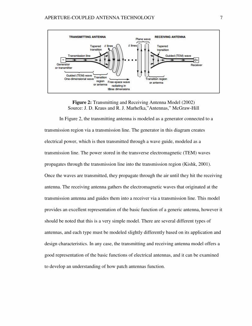
Figure 2: Transmitting and Receiving Antenna Model (2002)
Source: J. D. Kraus and R. J. Marhefka,”Antennas,” McGraw-Hill
In Figure 2, the transmitting antenna is modeled as a generator connected to a
transmission region via a transmission line. The generator in this diagram creates
electrical power, which is then transmitted through a wave guide, modeled as a
transmission line. The power stored in the transverse electromagnetic (TEM) waves
propagates through the transmission line into the transmission region (Kishk, 2001).
Once the waves are transmitted, they propagate through the air until they hit the receiving
antenna. The receiving antenna gathers the electromagnetic waves that originated at the
transmission antenna and guides them into a receiver via a transmission line. This model
provides an excellent representation of the basic function of a generic antenna, however it
should be noted that this is a very simple model. There are several different types of
antennas, and each type must be modeled slightly differently based on its application and
design characteristics. In any case, the transmitting and receiving antenna model offers a
good representation of the basic functions of electrical antennas, and it can be examined
to develop an understanding of how patch antennas function.

APERTURE-COUPLED ANTENNA TECHNOLOGY 8
Antenna Aperture
In addition to understanding the basic operation of antennas, an introduction to
the antenna aperture provides a foundation to conduct an assessment of aperture-coupled
antenna technology. The aperture of an antenna refers to the area of the antenna that is
oriented perpendicular to the incoming radio waves (Narayan, 2007). The antenna
aperture is a means of determining how well the antenna is able to receive the power
stored in radiating electromagnetic waves. Typically, a large antenna aperture is desirable
because more power is collected from the incoming electromagnetic fields as the aperture
size increases. The size of the effective area, or the antenna aperture, can be calculated
from the following equation when the gain of the antenna is measured or known:
�� � ��
4�
Equation 1: Effective Aperture
This equation states that the wavelength of the transmitted radio waves, lambda,
and the gain of the antenna, G, are directly related to the effective aperture of the antenna
(Kishk, 2001). This equation is useful for calculating the size of the aperture when the
antenna gain can be measured. In addition, the equation can be utilized to calculate the
gain of the antenna when the effective area is known.
The antenna aperture describes the amount of power that is captured from a
propagating electromagnetic wave. Thus, the effective aperture of an antenna can be used
to relate the power propagating through electromagnetic waves to the power that is
transmitted to the receiver. The following equation describes the relationship between the
aperture, transmitted power, and the propagating power.

APERTURE-COUPLED ANTENNA TECHNOLOGY 9
� � ���
Equation 2: Transmitted Power
In Equation 2, Pt refers to the power that is transmitted to the antenna (in Watts).
The propagating power density, p, is measured in watts per meter squared, and the
aperture is measured in meters squared (Kishk, 2001). The equation states that the
propagating power times the size of the aperture is equal to the transmitted power. From
this equation it can be seen that the larger the size of the effective aperture, the larger the
amount of power that will be transferred to the antenna’s receiver. This equation is useful
because it shows that the size of the effective aperture of an antenna is one of the most
important parts of the antenna’s design. Understanding the concept of antenna aperture is
necessary for beginning to assess aperture-coupled antenna technology. While this thesis
does not attempt to discuss the design of antenna apertures, it is important to note that the
aperture is one of the most important parts of antenna design.
Bandwidth and Impedance Matching
Another key topic to understand in antenna theory is the concept of bandwidth.
Developing an understanding of the concept of bandwidth is fundamental for any type of
antenna analysis because this parameter directly relates to how an antenna is designed
and how the antenna can perform. The bandwidth of an antenna is defined as the range of
frequencies over which the antenna can function as designed (Bevelacqua, 2010).
Bandwidth is typically a key parameter in antenna design because the desired operating
frequency for the antenna's application is usually known. For example, FM radio signals
vary from 88 megahertz to 108 megahertz, thus an antenna designed to receive FM radio
signals would need to be able operate within this bandwidth. The bandwidth of an

APERTURE-COUPLED ANTENNA TECHNOLOGY 10
antenna is related to the quality of the impedance match between the antenna, the source,
and the transmission line. As the operating frequency moves outside of the antenna's
bandwidth, the performance suffers because of an impedance mismatch (Bevelacqua,
2010). As the operating frequency changes, the imaginary component of the impedances
will change as well. As the impedances change, they can become mismatched at certain
frequencies and thus can affect the antenna's performance. For this reason, impedance
matching must be considered so that the antenna can operate over the desired frequency
range.
It is understood that the components of the antenna must be matched according to
their impedances in order for the antenna to operate as designed. Because the quality of
impedance matching affects the bandwidth of the antenna, the conditions of matching
that allow the maximum amount of power to be transmitted from the voltage source to
the antenna must be known. In order to describe the concept of impedance matching, the
antenna model shown below in Figure 3 will be examined.
Figure 3: Impedance Model of an Antenna (2008)
Source: http://www.antenna-theory.com/basics/impedance.php
In Figure 3, a basic antenna is modeled as a combination of a voltage source,
source impedance, and antenna impedance. In the diagram, V refers to the magnitude of
APERTURE-COUPLED ANTENNA TECHNOLOGY 11
the voltage source, ZS refers to the source impedance, and ZA refers to the antenna
impedance. The power that is delivered to the antenna can be utilized to understand how
the bandwidth affects the antenna's performance. Voltage division can be performed to
derive an expression for the power delivered to the antenna. It is widely understood in
electrical engineering that the following equation relates the power to the current and
voltage of a system.
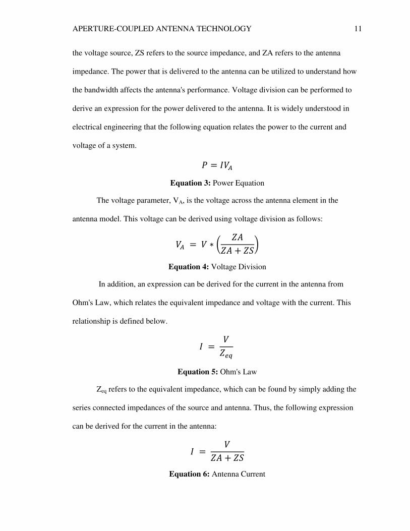
� ��
Equation 3: Power Equation
The voltage parameter, VA, is the voltage across the antenna element in the
antenna model. This voltage can be derived using voltage division as follows:
�� � � � � ���� � ���
Equation 4: Voltage Division
In addition, an expression can be derived for the current in the antenna from
Ohm's Law, which relates the equivalent impedance and voltage with the current. This
relationship is defined below.
� ����
Equation 5: Ohm's Law
Zeq refers to the equivalent impedance, which can be found by simply adding the
series connected impedances of the source and antenna. Thus, the following expression
can be derived for the current in the antenna:
� ��� � ��
Equation 6: Antenna Current

APERTURE-COUPLED ANTENNA TECHNOLOGY 12
Substituting Equation 4 and Equation 6 into Equation 3 yields an expression for
the power delivered to the antenna, shown below.
� �� � ����� � ����
Equation 7: Power Delivered to the Antenna
A few observations can be gathered from Equation 7 regarding the characteristics
of the antenna in the model. First, it can be seen that a very small antenna impedance,
ZA, will result in a small amount of power being transferred to the antenna. In other
words, as the impedance of the antenna approaches zero, the power delivered to the
antenna also approaches zero. The same is true for the opposite scenario; if ZA is very
large, very little power is delivered to the antenna. The nature of this equation proves that
the impedance of the antenna and the source must be designed so that the maximum
amount of power can be transferred to the antenna. It is widely known and accepted in
the field of electrical engineering that the characteristic for maximum power transfer is as
follows:
�� � ���
Equation 8: Maximum Power Transfer Condition
This condition states that the condition for maximum power transfer from the
source to the load is dependent upon the imaginary components of the impedances being
conjugate to one another. When ZA is conjugate to ZS, the reactances (the imaginary
components of the impedances) are opposite in sign. The summed reactances in the
denominator in Equation 7 result in the imaginary components cancelling each other,
minimizing the value in the denominator. This condition results in maximum power
APERTURE-COUPLED ANTENNA TECHNOLOGY 13
transfer to the load antenna. Since maximum power transfer occurs when the equivalent
impedance is a real value, the concept can be simplified to focus solely on real values for
ZS and ZA.
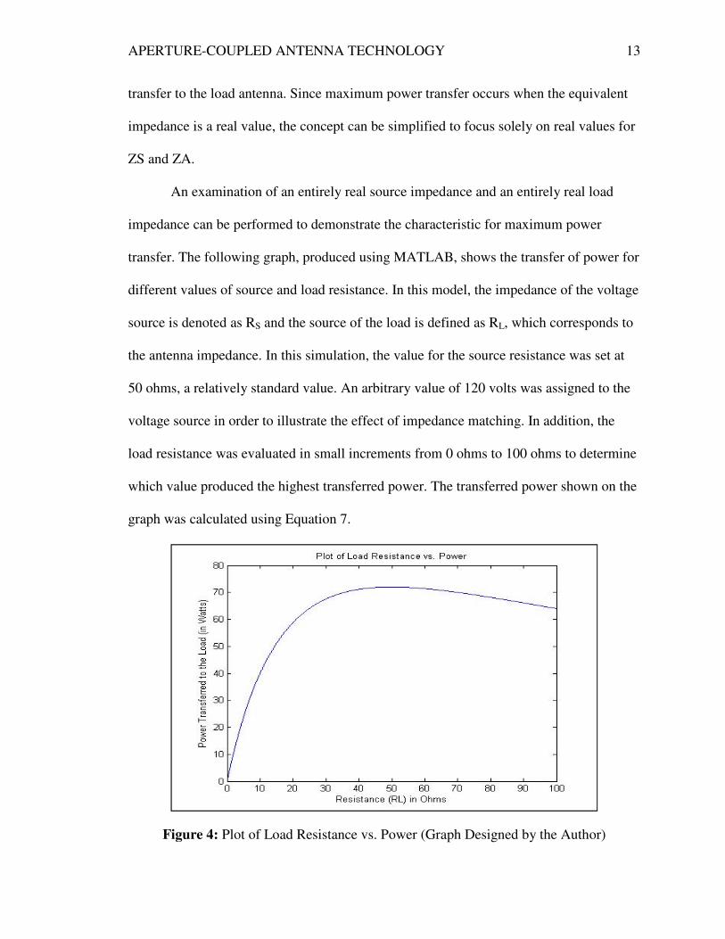
An examination of an entirely real source impedance and an entirely real load
impedance can be performed to demonstrate the characteristic for maximum power
transfer. The following graph, produced using MATLAB, shows the transfer of power for
different values of source and load resistance. In this model, the impedance of the voltage
source is denoted as RS and the source of the load is defined as RL, which corresponds to
the antenna impedance. In this simulation, the value for the source resistance was set at
50 ohms, a relatively standard value. An arbitrary value of 120 volts was assigned to the
voltage source in order to illustrate the effect of impedance matching. In addition, the
load resistance was evaluated in small increments from 0 ohms to 100 ohms to determine
which value produced the highest transferred power. The transferred power shown on the
graph was calculated using Equation 7.
Figure 4: Plot of Load Resistance vs. Power (Graph Designed by the Author)

APERTURE-COUPLED ANTENNA TECHNOLOGY
From Figure 4 it can be seen that the power delivered to the load reaches a
maximum when RL is equal to 50 ohms. This confirms that the maximum power transfer
occurs when the load resistance is equal to the source resistance. This concept extends to
complex impedances that are conjugate to each other, confirming the condition stated in
Equation 8. When the impedances are matched so that the maximum amount of power is
transferred from the source to the antenna, the antenna performs
As the frequency shifts away from the designed operating frequency the impedance of the
source and antenna shift as well, causing an impedance mismatch. As the impedances
become less matched to each other, the power transferred to the antenna decreases, an
thus the performance of the antenna drops. This principle states that there is a certain
frequency range, known as the bandwidth, for which the antenna can perform adequately.
The effect of an antenna's bandwidth can be illustrated by the following diagr
Source: http://commons.wikimedia.org/wiki/File:Bandwidth.svg
Figure 5 provides a visual representation of the relationship between operating
frequency and delivered power. It can be seen in the figure that the b
to f2. The figure clearly shows that less power is transferred outside of the frequency
COUPLED ANTENNA TECHNOLOGY
From Figure 4 it can be seen that the power delivered to the load reaches a
maximum when RL is equal to 50 ohms. This confirms that the maximum power transfer
occurs when the load resistance is equal to the source resistance. This concept extends to
x impedances that are conjugate to each other, confirming the condition stated in
Equation 8. When the impedances are matched so that the maximum amount of power is
transferred from the source to the antenna, the antenna performs at its highest potential
As the frequency shifts away from the designed operating frequency the impedance of the
source and antenna shift as well, causing an impedance mismatch. As the impedances
become less matched to each other, the power transferred to the antenna decreases, an
thus the performance of the antenna drops. This principle states that there is a certain
frequency range, known as the bandwidth, for which the antenna can perform adequately.
The effect of an antenna's bandwidth can be illustrated by the following diagr
Figure 5: Bandwidth vs. Power (2007)
http://commons.wikimedia.org/wiki/File:Bandwidth.svg
Figure 5 provides a visual representation of the relationship between operating
frequency and delivered power. It can be seen in the figure that the bandwidth is from f
. The figure clearly shows that less power is transferred outside of the frequency
14
From Figure 4 it can be seen that the power delivered to the load reaches a
maximum when RL is equal to 50 ohms. This confirms that the maximum power transfer
occurs when the load resistance is equal to the source resistance. This concept extends to
x impedances that are conjugate to each other, confirming the condition stated in
Equation 8. When the impedances are matched so that the maximum amount of power is
at its highest potential.
As the frequency shifts away from the designed operating frequency the impedance of the
source and antenna shift as well, causing an impedance mismatch. As the impedances
become less matched to each other, the power transferred to the antenna decreases, and
thus the performance of the antenna drops. This principle states that there is a certain
frequency range, known as the bandwidth, for which the antenna can perform adequately.
The effect of an antenna's bandwidth can be illustrated by the following diagram:
http://commons.wikimedia.org/wiki/File:Bandwidth.svg
Figure 5 provides a visual representation of the relationship between operating
andwidth is from f1
. The figure clearly shows that less power is transferred outside of the frequency

APERTURE-COUPLED ANTENNA TECHNOLOGY 15
range, and that the maximum power occurs at the center frequency, also known as the
design frequency. These observations extend to the design of any antenna, as the design
frequency will produce the highest level of performance. As the antenna begins to operate
outside its bandwidth, the performance decreases dramatically. For these reasons
consideration of desired antenna bandwidth as well as the quality of impedance matching
is necessary when designing an antenna.
Patch Antenna Technology
Patch Antenna Fundamentals
Patch antennas are special types of radio antennas that feature a low-profile
design that is ideal for implementation in mobile applications (Kuchar, 1996). These
patch antennas are a special type of microstrip antenna, an antenna that is designed
around printed circuit board technology. Microstrip refers to a special type of
transmission line that can be printed using a circuit board printer. This technology is
advantageous because it allows patch antennas to be manufactured very inexpensively.
Patch antennas are typically mounted to flat surfaces, and feature a flat, rectangular shape
(Kuchar, 1996). Patch antennas are useful because they are fairly simple to manufacture,
they are relatively inexpensive to fabricate, and they are easy to modify after they are
created. Figure 6, shown below, shows an assembled patch antenna.

APERTURE-COUPLED ANTENNA TECHNOLOGY 16
Figure 6: Patch Antenna Example (2008)
Source:http://www.propagation.gatech.edu/ECE6390/project/Fall2008/Kuato/web/Comm
Sys_RXAntenna.html
Patch antennas are constructed differently than a typical antenna due to their
distinct applications. As mentioned above, patch antennas are typically rectangular in
shape, and can vary in size based on the needs of the user or based on the application.
These antennas are often implemented in mobile communications and cellular telephone
applications (Civerolo, 2011). The patch antenna consists of a flat sheet of metal, known
as the “patch”, and another large sheet of metal known as the “ground plane.” In the
image above, the smaller rectangle is the patch and the large copper sheet serves as the

APERTURE-COUPLED ANTENNA TECHNOLOGY 17
ground plane. A typical patch antenna is constructed by placing a metal ground plate
under a dielectric substrate, and then placing the micro-strip transmission line and patch
antenna on top of that substrate (Civerolo, 2011). Figure 7, displayed on the following
page, shows a side view of a standard patch antenna construction:
Figure 7: Typical Patch Antenna (Side View) (2014) Image adapted by the author from
content at http://www.antenna-theory.com/antennas/patches/antenna.php
Figure 7 offers a representation of a very simply designed patch antenna. In this
model a ground plane is separated from the patch antenna by a dielectric substrate. When
a feed, or input voltage, is applied to the microstrip transmission line, electromagnetic
fields propagate between the patch antenna and the ground plane within the dielectric
substrate. These fields then radiate outward from the antenna to be picked up by a
receiving antenna (Bevelacqua, 2010).
There are numerous types of patch antennas that can vary based on application,
bandwidth, gain, and range. The performance of the antenna can be adjusted with varying
methods of construction. The material that is used in the construction of the antenna can
directly affect the antenna’s performance, which must be considered by the designer. In

APERTURE-COUPLED ANTENNA TECHNOLOGY 18
addition, the layers and dimensions of the patch antenna can be adjusted based on design
needs. An alternative patch antenna design is shown in Figure 8 below:
Figure 8: Alternative Patch Antenna Construction (Aperture-coupled) (n.d.)
Source:http://eee.guc.edu.eg/Courses/Communications/COMM905%20Advanced%20Co
mmunication%20Lab/Sessions/Session%204.pdf
In Figure 8, the patch antenna is constructed similar to the one shown in Figure 7,
with the exception that an additional layer of substrate is added on the bottom that
contains the micro-strip feed line (Kuchar, 1996). This type of patch antenna is called an
aperture-coupled antenna, which will be discussed in further detail in the following
APERTURE-COUPLED ANTENNA TECHNOLOGY 19
section. The center layer of the antenna shown in Figure 4 houses a coupling aperture,
which will be also examined in the analysis of aperture-coupled antenna technology.
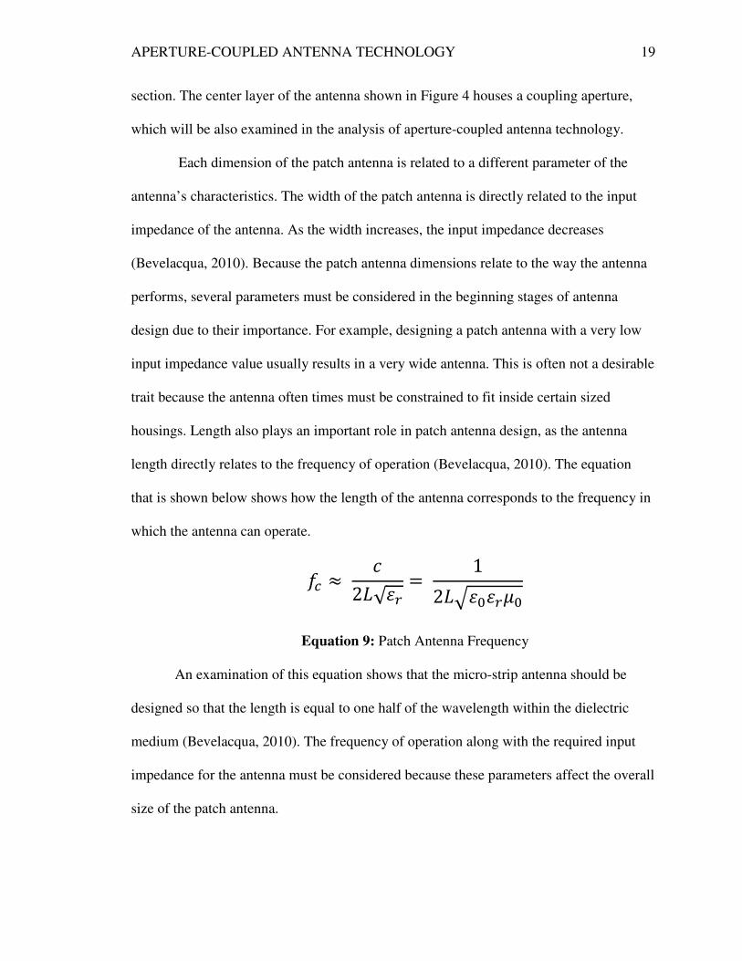
Each dimension of the patch antenna is related to a different parameter of the
antenna’s characteristics. The width of the patch antenna is directly related to the input
impedance of the antenna. As the width increases, the input impedance decreases
(Bevelacqua, 2010). Because the patch antenna dimensions relate to the way the antenna
performs, several parameters must be considered in the beginning stages of antenna
design due to their importance. For example, designing a patch antenna with a very low
input impedance value usually results in a very wide antenna. This is often not a desirable
trait because the antenna often times must be constrained to fit inside certain sized
housings. Length also plays an important role in patch antenna design, as the antenna
length directly relates to the frequency of operation (Bevelacqua, 2010). The equation
that is shown below shows how the length of the antenna corresponds to the frequency in
which the antenna can operate.
�� � �2�√ !
� 12�# $ !%$
Equation 9: Patch Antenna Frequency
An examination of this equation shows that the micro-strip antenna should be
designed so that the length is equal to one half of the wavelength within the dielectric
medium (Bevelacqua, 2010). The frequency of operation along with the required input
impedance for the antenna must be considered because these parameters affect the overall
size of the patch antenna.

APERTURE-COUPLED ANTENNA TECHNOLOGY 20
Patch antennas are designed to function like any other antenna. They are able to
receive and transmit electromagnetic energy through propagating waves. The method in
which the power is transferred into electromagnetic wave radiation is slightly different in
patch antennas than the typical ideal antenna model. In the ideal antenna model, energy is
applied to the antenna and radiates from the top peak of the antenna. In the ideal model,
the peak of the antenna is considered to be a point that allows for energy to radiate in
every direction. The electromagnetic energy in the ideal antenna model radiates in an
omnidirectional pattern. In patch antenna technology, electric and magnetic fields are
created between the patch and the ground plane. The electric fields then combine with
each other in phase to produce electromagnetic radiation from the micro-strip antenna
(Bevelacqua, 2010). This results in a more directional pattern of electromagnetic
radiation than the ideal model. The main difference between a standard wire antenna and
a patch antenna is that patch antennas utilize voltage distribution to create
electromagnetic radiation. In contrast, standard wire antennas radiate electromagnetic
energy due to the summation of currents along the transmission line that composes the
antenna. Figure 9, shown below, shows how electromagnetic fields gather between the
patch and the ground plane on the antenna.

APERTURE-COUPLED ANTENNA TECHNOLOGY 21
Figure 9: Fields inside a Patch Antenna (2014) Image adapted by the author from content
at http://www.antenna-theory.com/antennas/patches/antenna.php
It is easy to see from the diagram that electromagnetic fields gather under the
patch inside the dielectric. These fields combine to a point where they are able to radiate
outward from the antenna, as they can no longer be contained within the dielectric.
Depending on the design of the patch antenna, this radiation can be more direct than the
spherical pattern produced in standard wire antenna applications (Bevelacqua, 2010).
Microstrip Patch Antenna Applications
Microstrip antennas have been implemented in several communications based
industries because of their many benefits. The technology has been implemented in a
variety of military, commercial, and private applications due to the ability to design and
implement the antennas at low cost. One of the major reasons microstrip antennas are
becoming more popular is their low-profile and compact design, which allows these
antennas to be incorporated into a plethora of electronic devices. Microstrip antennas are
utilized in several different industries because of the ability to design the antennas with
different optimizations based on the desired application. To understand the many usages
for microstrip antenna technology, three different industries will be examined in order to

APERTURE-COUPLED ANTENNA TECHNOLOGY 22
discover the potential for the technology. The military, commercial, and private
applications of these antennas will be examined to provide a foundation for
understanding the benefit of researching and developing microstrip antenna technology.
Microstrip patch antennas have been utilized in a variety of military applications.
These antennas are often utilized in aircraft, radios, submarines, and land vehicles.
Microstrip patch antennas are often incorporated into airplanes because of their slim and
compact design. The small physical size of these antennas allows them to be
implemented into the cockpit of an airplane without impeding other physical hardware.
Microstrip patch antennas have more recently been utilized in unmanned aerial vehicles.
In these applications the antenna allows the aircraft to receive signals from a user that is
located on the ground many miles away. This application of patch antenna technology
allows a user to control the aircraft without actually being on board. Unmanned aerial
vehicles have become a key component in many branches of the military due to their
ability to survey and attack enemy locations without the threat to human life. Microstrip
antenna technology is a key component that makes it possible for the military to control
these aircrafts from across vast distances.
In addition to their applications in unmanned aerial vehicle applications, patch
antennas have often been incorporated inside military radios and submarines for
communications purposes. Again, the small physical dimensions of these antennas allow
them to be incorporated into communications devices without increasing the size of the
equipment. The small physical size of microstrip antennas makes them ideal candidates
for incorporation into submarines, radios, and other applications where space is limited.
Microstrip antennas are implemented in military applications because they can be
APERTURE-COUPLED ANTENNA TECHNOLOGY 23
designed and sized based on the application while still providing adequate performance
for the user.
In addition to their various usages in military applications, microstrip antennas are
also widely used in the communications industry. As technology continues to become
more sophisticated, electronic devices tend to get smaller in size. Thus, the desire is to
design an antenna that requires less space and less power but still offers reliable
performance. Microstrip antenna technology provides a bridge between performance and
size for the communications industry. Cellular telephones, tablets, and laptop computers
can incorporate microstrip patch antennas in their designs while still maintaining a slim
profile. This is beneficial to electronics manufacturers because it allows for them to
design products that perform well and are aesthetically appealing. The development of
microstrip antenna technology has allowed the communications industry to grow rapidly
because the antennas offer good performance, quality, and adaptability for the
manufacturer.
As patch antennas have continued to make an impact in the military and
communications industries, private applications for the technology have become
prominent as well. Individuals with an interest in antenna theory and construction can
design, build, and test their own microstrip patch antenna with supplies from an
electronics store and a microstrip printer. The ability to design and create a patch antenna
at home has allowed enthusiasts to incorporate the technology into private applications.
The ability for an individual to be able to design, construct, and implement a patch
antenna at a low cost is another reason that microstrip antennas continue to be a
promising technology.

APERTURE-COUPLED ANTENNA TECHNOLOGY 24
Microstrip antenna technology has seen a dramatic increase in sophistication due
to its applications in the military, communications, and private industries. While the
specific implementations of these antennas may differ in each application, the main
benefits remain the same. The small size, ease of design and construction, low cost, and
adaptability are clear benefits of the technology to be considered in evaluation.
Aperture-coupled Antenna Technology
Introduction to Aperture-coupled Antenna Technology
The assessment of aperture-coupled antenna technology is aided by establishing a
background in antenna theory and patch antenna design and function. Once these two
foundational principles are understood, a thorough assessment of the aperture-coupled
antennas can be conducted. In this assessment of aperture-coupled antenna technology,
basic functions, drawbacks, and benefits will be examined to draw conclusions as to
whether or not the field of aperture-coupled antenna technology is worth pursuing. Since
this technology is already over twenty five years old, it can be assumed from the start of
this assessment that there is some merit in using this technology. As discussed above,
there are apparent trade-offs that must take place when designing patch antennas. It is
reasonable to hypothesize that similar trade-offs will be encountered when assessing the
benefits and drawbacks of aperture-coupled antenna technology. The overall hypothesis
that can be developed simply from the knowledge of antenna theory and patch antenna
design is that aperture-coupled antenna technology is worth pursuing. Conclusions will
be drawn in order to confirm or disprove this hypothesis through research and
development the positive and negative aspects of aperture-coupled antennas.
APERTURE-COUPLED ANTENNA TECHNOLOGY 25
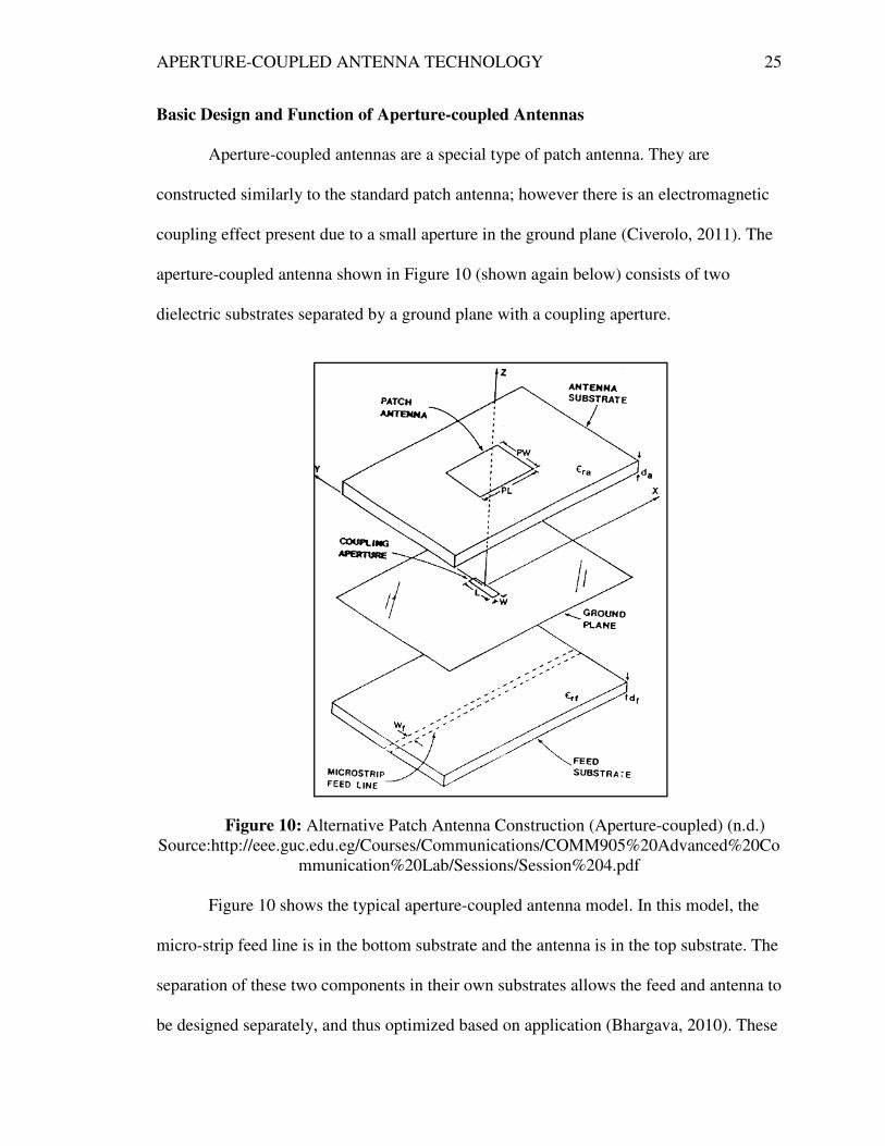
Basic Design and Function of Aperture-coupled Antennas
Aperture-coupled antennas are a special type of patch antenna. They are
constructed similarly to the standard patch antenna; however there is an electromagnetic
coupling effect present due to a small aperture in the ground plane (Civerolo, 2011). The
aperture-coupled antenna shown in Figure 10 (shown again below) consists of two
dielectric substrates separated by a ground plane with a coupling aperture.
Figure 10: Alternative Patch Antenna Construction (Aperture-coupled) (n.d.)
Source:http://eee.guc.edu.eg/Courses/Communications/COMM905%20Advanced%20Co
mmunication%20Lab/Sessions/Session%204.pdf
Figure 10 shows the typical aperture-coupled antenna model. In this model, the
micro-strip feed line is in the bottom substrate and the antenna is in the top substrate. The
separation of these two components in their own substrates allows the feed and antenna to
be designed separately, and thus optimized based on application (Bhargava, 2010). These

APERTURE-COUPLED ANTENNA TECHNOLOGY 26
two substrates are separated by a metal ground plane that contains a coupling aperture.
The incorporation of a coupling aperture brings about another set of design constraints,
which will be discussed in the coming sections dealing with the analysis of benefits and
drawbacks of aperture-coupled antenna technology.
There are several parameters that can affect the performance of an aperture-
coupled antenna including the thickness of the substrates, the dielectric constant of each
substrate, the patch length, the patch width, and the length and width of the aperture. In
aperture-coupled antenna design, the coupling aperture is actually a “slot” that is
designed based on the reaction of the antenna to the slot’s width and length. The overall
size of the aperture affects the coupling level of the antenna (Bhargava, 2010). The basic
function of the aperture, or slot, is to couple the energy from the micro-strip feed line to
the patch.
Patch Antenna Aperture Feed Technique
Numerous feed methods have been developed to supply patch antennas with the
power necessary to radiate electromagnetic energy. Some of these feed techniques
include inset feeding, coaxial cable (probe) feeding, indirect (coupled) feeding, and
aperture-coupled feeding. A brief examination of the aperture feeding technique is
valuable in understanding some of the benefits and drawbacks of the use of aperture-
coupled patch antennas. To begin the assessment of the aperture feeding technique an
examination of how an aperture-fed antenna is constructed is considered. Figure 11
shown below offers a visual representation of an aperture-fed patch antenna.

APERTURE-COUPLED ANTENNA TECHNOLOGY 27
Figure 11: Aperture-fed Antenna Construction (Side View) (2014) Image
adapted by the author from content at http://www.antenna-
theory.com/antennas/patches/antenna.php
In Figure 11 the transmission line carrying the power for the antenna is separated
from the patch antenna by two dielectric substrates and a conductive ground plane. The
presence of a conductive ground plane between the feed and the patch antenna forces the
electromagnetic radiation to travel through the dielectric substrate. This allows the energy
from the transmission line to be “directed” to the patch antenna without physically
connecting the two conductors to one another. The concept of transmitting energy from
the transmission line to the patch antenna without a physical connection of the conductors
is known as “coupling.” A hole exists in the ground plane to allow the electromagnetic
energy to pass through the dielectric substrate into the antenna. Because there are two
separate layers of dielectric substrate in this construction, each with a different
permittivity value, the electromagnetic energy can be directed so that the radiation from
the patch antenna is maximized. The lower level of substrate is typically constructed
using a dielectric with a very high permittivity, which allows for the electromagnetic
fields in the lower level to be tightly grouped together. When the fields are tightly

APERTURE-COUPLED ANTENNA TECHNOLOGY 28
grouped under the aperture, more electromagnetic energy is able to pass through the hole
in the ground plane into the second layer of substrate. A high permittivity value in the
lower substrate typically eliminates the potential losses due to the spread of
electromagnetic energy into the ground plane. In contrast to the lower level, the upper
level of dielectric substrate typically features a much lower permittivity value, allowing
the electromagnetic fields to be loosely grouped inside the second layer of dielectric
material. The loose grouping of the electromagnetic fields in the upper level of substrate
promotes increased radiation from the patch antenna, which in turn increases the
microstrip antenna's overall performance.
Developing and understanding of how aperture-fed antennas are constructed helps
uncover some of the benefits of aperture-coupled antenna technology. The ability to
independently design the feed and the patch antenna is a benefit that will be discussed
further in the upcoming sections.
Analysis of Benefits and Drawbacks
The same design principles apply to aperture-coupled antennas that apply to all
patch antennas. The width of the micro-strip antenna directly corresponds to the input
impedance of the antenna. While it is often desirable to design antennas to small input
impedances, such as 50 ohms, it is not always feasible based on size constraints. Thus,
like patch antennas, aperture-coupled antennas must be carefully designed so that they
meet the needs of the application. The addition of an aperture in patch antenna design
creates added design constraints. One of the drawbacks of using aperture-coupled antenna
technology is the existence of added constraints in the patch antenna design. Additional
constraints and changing parameters are never ideal in design because they often generate

APERTURE-COUPLED ANTENNA TECHNOLOGY 29
tradeoffs between performance and utility (Bevelacqua, 2010). The presence of the
additional substrate and the coupling aperture in aperture-coupled antennas requires the
antenna to meet even more design criteria than a typical patch antenna. Instead of only
having to design one type of dielectric the designer must design two layers consisting of
different dielectric. This characteristic of aperture-coupled antennas results in a longer
and more complicated design process than a standard patch antenna. This drawback,
while not desirable, is not detrimental to the overall usefulness of the technology.
A second drawback in aperture-coupled antenna technology is the increased
antenna size that results from the incorporation of another layer of substrate in the
antenna construction. This property of aperture-coupled antennas can be both a drawback
and a positive aspect of the technology. While the additional substrate allows the feed
and the patch antenna to be designed and optimized separately, there is often an
additional physical width present when incorporating two different dielectric substrates in
the antenna’s construction. The addition of another layer of substrate often results in a
thicker antenna because more dielectric material is present when compared to a basic
patch antenna. This is another example of tradeoff in design, as the designer must decide
whether it is more important to optimize the antenna and feed parameters separately, or to
design the patch antenna around size constraints. As stated previously, one of the overall
benefits of patch antennas is their ability to be incorporated into small devices. Additional
size is not usually desirable in today’s technology, thus the presence of the additional
substrate is often undesired as well.
In addition to the drawbacks of the aperture-coupled antenna, there are also
several advantages to the technology that are not present in typical patch antenna designs.

APERTURE-COUPLED ANTENNA TECHNOLOGY 30
As stated above, the use of aperture coupling and the presence of an additional substrate
allow the antenna to be designed separately from the feed. This in turn implies that
aperture-coupled antennas can be incorporated into a variety of applications when size is
not an issue, because these antennas can conform to the voltage and power supplies in
different devices without adjusting the antenna properties. This is a very useful
application in the field of communications because aperture coupling can be utilized to
adapt the same antenna to several different devices.
Another benefit of aperture coupling in patch antenna design is that the radiation
pattern produced by the antenna is often more symmetric. This is an extremely beneficial
characteristic of aperture-coupled antennas, as symmetrically radiating electromagnetic
waves are much easier for receiving antennas to capture. The more symmetric the
electromagnetic radiating waves, the better the pattern of radiation can be predicted and
thus captured by a receiving antenna. This is an extremely important advantage of
aperture coupling because it allows the antenna portion of the design to be extremely
accurate and reliable. In addition to a more symmetric pattern of radiation, aperture-
coupled antennas reduce the radiation from the transmission line feed, which maximizes
the radiation from the antenna. This is important because it eliminates interference and
conflicting radiation between the feed and antenna substrates.
Another more obvious benefit of aperture-coupled antennas is their ability to be
mounted in low profile applications. The flat and rectangular nature of aperture-coupled
antennas is ideal for incorporation into mobile devices, wireless routers, and other types
of communications technology. Because the aperture-coupled patch antennas are small in
nature, they are very low cost to produce. In today’s technology market cost is an obvious

APERTURE-COUPLED ANTENNA TECHNOLOGY 31
factor in every decision and design. Aperture-coupled antennas are inexpensive to
produce, easy to modify, and can be incorporated into many different applications. These
factors make aperture-coupled antennas suitable for use in many electrical devices.
Conclusion
While there are numerous drawbacks and benefits to using aperture-coupled
antennas, it is clear that the benefits are far more significant than the drawbacks. The
varieties of applications that exist for aperture-coupled antennas in conjunction with the
adaptability of design make these antennas ideal for implementation in mobile
communications applications. In addition to the various applications of aperture-coupled
antennas, the antennas are also extremely cost effective. The low cost for the
manufacturing of these aperture-coupled antennas is a large reason that implementing
patch antennas is worthwhile. The ability to design aperture-coupled antennas to different
applications, the low cost of manufacturing these antennas, and the small physical size of
the antennas make them ideal for implementation in the field of communications. Thus, it
can be concluded that the hypothesis outlined above is confirmed, aperture-coupled
antenna technology is certainly worth pursuing.
In assessing the field of aperture-coupled antenna technology, it is helpful to
develop an understanding of antenna theory and patch antenna design before determining
the effectiveness of aperture coupling. Antenna theory provides a foundational
understanding for why patch antennas and aperture coupling exist. The utilization of
antennas to transmit and receive electromagnetic waves allows the devices to be
implemented in a variety of industries, primarily in the field of communications. Patch
antennas, a special type of antenna that features a low-profile rectangular design, are

APERTURE-COUPLED ANTENNA TECHNOLOGY 32
useful in mobile electronics because they are inexpensive to produce, easy to
manufacture, and can fit inside small spaces based on the application. Aperture coupling
is a technique used to create a more modular patch antenna because it allows the antenna
and feed to be designed separately, thus increasing the antennas overall performance. The
aperture-coupled antenna is a suitable technology to research and develop because of its
vast amount of applications, low production cost, and modularity.

APERTURE-COUPLED ANTENNA TECHNOLOGY 33
References
Bakshi, K.A.; A.V.Bakshi, U.A.Bakshi (2009). Antennas and wave propagation.
Waltham, MA: Technical Publications.
Bevelacqua, Peter. 2011. Microstrip (Patch) Antennas. Microstrip antennas: the patch
antenna. N.p., 2011. Web. 9 Nov. 2013. Retrieved from <http://www.antenna-
theory.com/antennas>.
Bhargava, Srivatsa. Aperture-coupled wide-band micro strip antenna design. New
York City: MTech, 2010. Print.
Civerolo, Michael. Aperture-coupled antenna design methods. San Luis Obispo, CA:
California Polytechnic State University, 2011. Print.
HFSS, Ansoft Corporation: User's guide, version 10 - high frequency
structure simulator. Pittsburgh, PA: Ansoft Corporation, 220-238,
2005.
Kishk, Ahmed. Fundamentals of antennas. Oxford, MS: McGraw-Hill, 2001.
Print.
Kuchar, A. (1996). Aperture-coupled microstrip patch antenna array.
M.S. Thesis, Technische Universität Wien, March 1996.
Narayan, C.P. (2007). Antennas and propagation. Waltham, MA: Technical
Publications. 35-51
Related Documents
![Analysis of Cavity Introduced Aperture Coupled Feed Antenna · 2020. 1. 7. · [4] Getting Started: Ansoft HFSS 8.0, Section 3: Projects, HFSS Design Flow [5] A Reconfigurable Aperture](https://static.cupdf.com/doc/110x72/60da10ec6753db0eee4354a5/analysis-of-cavity-introduced-aperture-coupled-feed-antenna-2020-1-7-4-getting.jpg)


