arXiv:0709.4048v1 [cs.DC] 25 Sep 2007 A Symphony Conducted by BruNet P. Oscar Boykin Department of Electrical and Computer Engineering University of Florida Jesse S. A. Bridgewater Electrical Engineering Department University of California, Los Angeles Joseph S. Kong Electrical Engineering Department University of California, Los Angeles Kamen M. Lozev Electrical Engineering Department University of California, Los Angeles Behnam A. Rezaei Electrical Engineering Department University of California, Los Angeles Vwani P. Roychowdhury Electrical Engineering Department University of California, Los Angeles Abstract We introduce BruNet, a general P2P software frame- work which we use to produce the first implementation of Symphony, a 1-D Kleinberg small-world architecture. Our framework is designed to easily implement and mea- sure different P2P protocols over different transport lay- ers such as TCP or UDP. This paper discusses our im- plementation of the Symphony network, which allows each node to keep k ≤ log N shortcut connections and to route to any other node with a short average delay of O( 1 k log 2 N ). We present experimental results taken from several PlanetLab deployments of size up to 1060 nodes. These successful deployments represent some of the largest PlanetLab deployments of P2P overlays found in the literature, and show our implementation’s robust- ness to massive node dynamics in a WAN environment. 1 Introduction: Motivation and Summary of Results Peer-To-Peer (P2P) networking is an increasingly pop- ular network model where nodes communicate directly without utilizing a centralized server. In recent years, P2P file-sharing applications have flourished. A recent study shows that P2P systems are responsible for ap- proximately one half of the network traffic at a major university[1] and comprise a significant fraction of total Internet traffic. For a review of P2P search systems, see [2]. There are three novel contributions reported in this work. First, we describe a new P2P software framework called BruNet. The BruNet framework handles most of the issues common to all P2P protocols such as dealing with firewalls and NATs, connecting nodes, and routing packets. Secondly, we use the BruNet P2P framework to implement Symphony[3], a 1-D Kleinberg routable small-world network[4, 5]. This is the first implemen- tation of a 1-D routable small-world network. Third, we report on large scale PlanetLab tests involving more than 1000 nodes, which puts the P2P networks described here amongst the largest P2P networks to be tested on Plan- etLab. These deployments demonstrate our implemen- tation’s robustness to massive node dynamics in a WAN environment. Our BruNet software architecture manages P2P packet routing and connection maintenance. Given a packet with a particular destination address A, the system will deliver the packet to the node closest to that address. This sort of routing primitive may be used to build a dis- tributed hash table (DHT), which is common in the P2P literature. Clearly, the success and efficacy of such an ad-hoc addressing and routing scheme depends on the robustness of the overlay structured networks. The deployment of DHT P2P systems such as the Kademlia-based[6] eDonkey, which already supports about a million simultaneous users, indicates that large- scale overlay networks are feasible. The existence of such large-scale DHT systems is impressive, however the performance of P2P networks at that scale has not yet been systematically studied. While we have not yet scaled to one million nodes, our experiments of more than 1,000 nodes is amongst largest P2P networks to be tested on PlanetLab. The data we obtained from deploy- ments of our system on PlanetLab show that the struc- tured routing network can indeed be bootstrapped from a random initial network, and can be robust to high rates of joins and departures of participating nodes. We chose Symphony, the 1-D Kleinberg routable small-world network[3, 4, 5] as the topology for the structured overlay network. This ringlike address space entails simple routing calculations and requires very low node state. Our structured overlay is currently the only implementation of a 1-D Kleinberg routable small-world network; as reviewed in the next section, a number of schemes that utilize the 1-D small-world model have been proposed, but to the best knowledge of the au- thors none have been deployed and tested in a WAN 1

Welcome message from author
This document is posted to help you gain knowledge. Please leave a comment to let me know what you think about it! Share it to your friends and learn new things together.
Transcript

arX
iv:0
709.
4048
v1 [
cs.D
C]
25 S
ep 2
007
A Symphony Conducted by BruNetP. Oscar Boykin
Department of Electrical and Computer EngineeringUniversity of Florida
Jesse S. A. BridgewaterElectrical Engineering Department
University of California, Los Angeles
Joseph S. KongElectrical Engineering Department
University of California, Los Angeles
Kamen M. LozevElectrical Engineering Department
University of California, Los Angeles
Behnam A. RezaeiElectrical Engineering Department
University of California, Los Angeles
Vwani P. RoychowdhuryElectrical Engineering Department
University of California, Los Angeles
Abstract
We introduce BruNet, a general P2P software frame-work which we use to produce the first implementationof Symphony, a 1-D Kleinberg small-world architecture.Our framework is designed to easily implement and mea-sure different P2P protocols over different transport lay-ers such as TCP or UDP. This paper discusses our im-plementation of the Symphony network, which allowseach node to keepk ≤ log N shortcut connections andto route to any other node with a short average delayof O( 1
klog2 N). We present experimental results taken
from several PlanetLab deployments of size up to 1060nodes. These successful deployments represent some ofthe largest PlanetLab deployments of P2P overlays foundin the literature, and show our implementation’s robust-ness to massive node dynamics in a WAN environment.
1 Introduction: Motivation and Summaryof Results
Peer-To-Peer (P2P) networking is an increasingly pop-ular network model where nodes communicate directlywithout utilizing a centralized server. In recent years,P2P file-sharing applications have flourished. A recentstudy shows that P2P systems are responsible for ap-proximately one half of the network traffic at a majoruniversity[1] and comprise a significant fraction of totalInternet traffic. For a review of P2P search systems, see[2].
There are three novel contributions reported in thiswork. First, we describe a new P2P software frameworkcalled BruNet. The BruNet framework handles most ofthe issues common to all P2P protocols such as dealingwith firewalls and NATs, connecting nodes, and routingpackets. Secondly, we use the BruNet P2P frameworkto implement Symphony[3], a 1-D Kleinberg routablesmall-world network[4, 5]. This is the first implemen-tation of a 1-D routable small-world network. Third, we
report on large scale PlanetLab tests involving more than1000 nodes, which puts the P2P networks described hereamongst the largest P2P networks to be tested on Plan-etLab. These deployments demonstrate our implemen-tation’s robustness to massive node dynamics in a WANenvironment.
Our BruNet software architecture manages P2P packetrouting and connection maintenance. Given a packetwith a particular destination addressA, the system willdeliver the packet to the node closest to that address.This sort of routing primitive may be used to build a dis-tributed hash table (DHT), which is common in the P2Pliterature. Clearly, the success and efficacy of such anad-hoc addressing and routing scheme depends on therobustness of the overlay structured networks.
The deployment of DHT P2P systems such as theKademlia-based[6] eDonkey, which already supportsabout a million simultaneous users, indicates that large-scale overlay networks are feasible. The existence ofsuch large-scale DHT systems is impressive, howeverthe performance of P2P networks at that scale has notyet been systematically studied. While we have not yetscaled to one million nodes, our experiments of morethan 1,000 nodes is amongst largest P2P networks to betested on PlanetLab. The data we obtained from deploy-ments of our system on PlanetLab show that the struc-tured routing network can indeed be bootstrapped froma random initial network, and can be robust to high ratesof joins and departures of participating nodes.
We chose Symphony, the 1-D Kleinberg routablesmall-world network[3, 4, 5] as the topology for thestructured overlay network. This ringlike address spaceentails simple routing calculations and requires very lownode state. Our structured overlay is currently the onlyimplementation of a 1-D Kleinberg routable small-worldnetwork; as reviewed in the next section, a number ofschemes that utilize the 1-D small-world model havebeen proposed, but to the best knowledge of the au-thors none have been deployed and tested in a WAN
1
environment. Kleinberg proved that properly designedsmall-world networks could support efficient decentral-ized routing withO(log2N) latency. The proposed sys-tem uses a 160-bit address space to construct a ringlikestructure. Shortcuts are made in this ringlike addressspace according to a specific probability distribution[4].The analysis and simulation results in [3] show thatmaintainingk ≤ log N long-range neighbors improvesrouting latency toO( 1
klog2 N).
Our functioning implementation adds several new fea-tures to the routable small-world model, including ex-panded routing rules to permit firewall traversal and easybootstrapping and also to obtain a structured 1-D ringstarting from any initially connected network. Networksup to 1060 nodes have been deployed on PlanetLab, aswe discuss later in Section 5. A key goal of this effortis that the network remains routable in the presence ofmassive node dynamics including massive joins, massivefailures, ring merging and churn. The system’s robust-ness under heavy node dynamics compares very favor-ably to the results published for Tapestry[7]; moreover,our deployment has more than twice the number of nodesdealt with in [7].
The paper is laid out as follows: we first discuss re-lated work in the following section. Section 3 describesthe BruNet software architecture and system compo-nents. Section 3 also includes our approach to travers-ing firewalls and NAT devices. Section 4 provides de-tails on our Symphony implementation. Finally, Section5 presents PlanetLab experiments that demonstrate thecorrectness and robustness of the network.
2 Related Work
There has been much recent work on producing struc-tured P2P overlays with distributed hash table (DHT)interfaces. Some examples of these structured systemsinclude [8, 9, 10, 11, 12, 13, 7, 14, 6, 3]. The main ad-vantages of these structured DHT systems are scalableobject location inO(log N) or O(log2 N) steps and theguaranteed retrieval of any existing object.
This paper reports on an implementation and measure-ments rather than simulation of a P2P network. Whilethere are many reports of simulations of structured P2Pprotocols, the measurement of such protocols in realworld WAN environments has rarely been addressed(e.g. [7]).
Among the existing structured systems, there are sev-eral Kleinberg-inspired small-world P2P overlays: Sym-phony [3] provides a detailed software design for a DHTsystem based on a unit-circumference ring; Accordion[15] is a proposed small-world-based structured systemdesigned to provide efficient bandwidth management ofthe distributed routing tables; Mercury [16] presents a
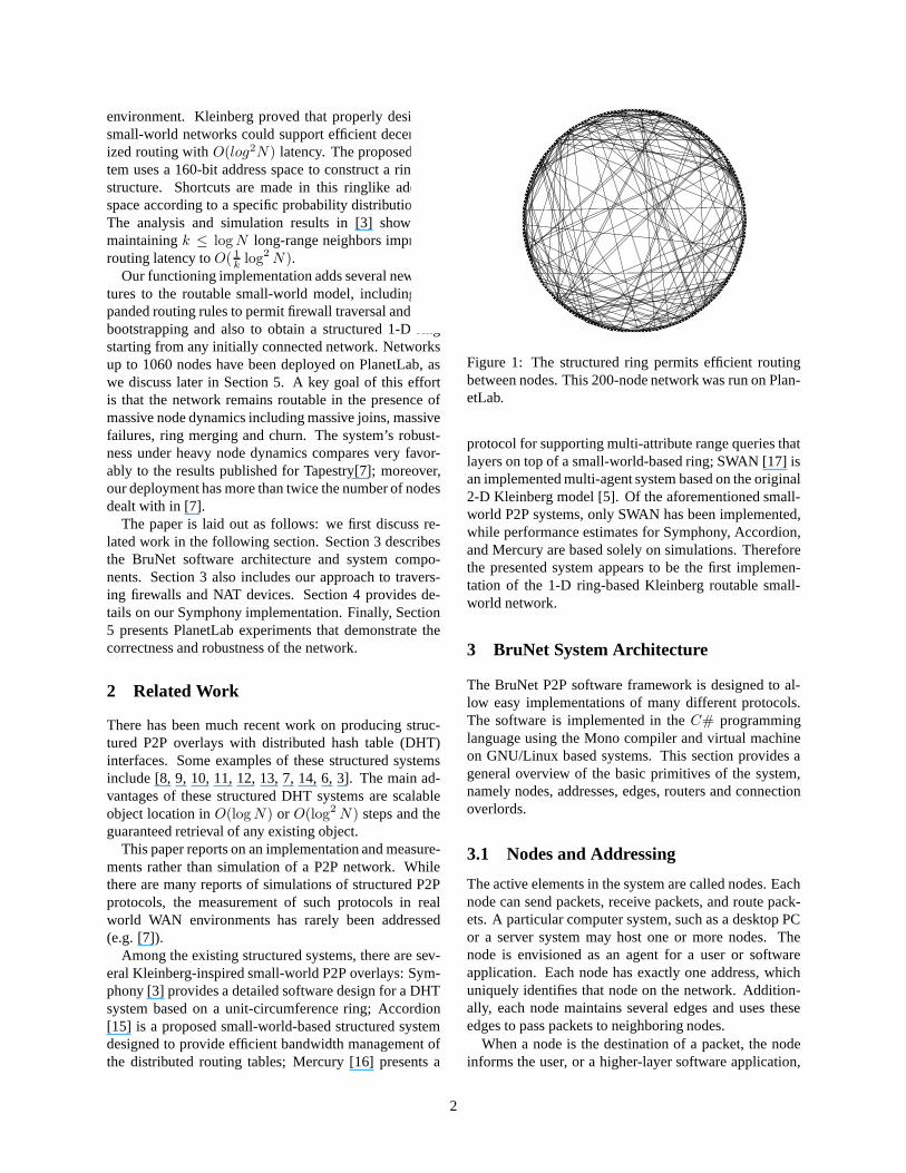
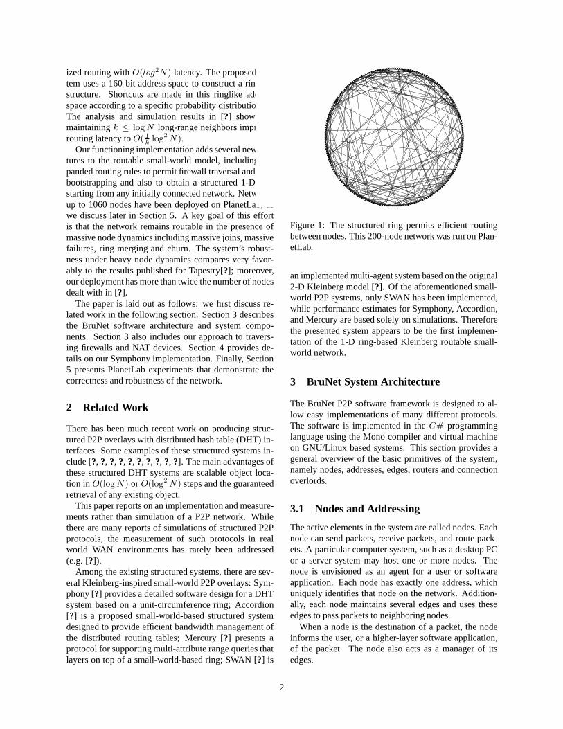
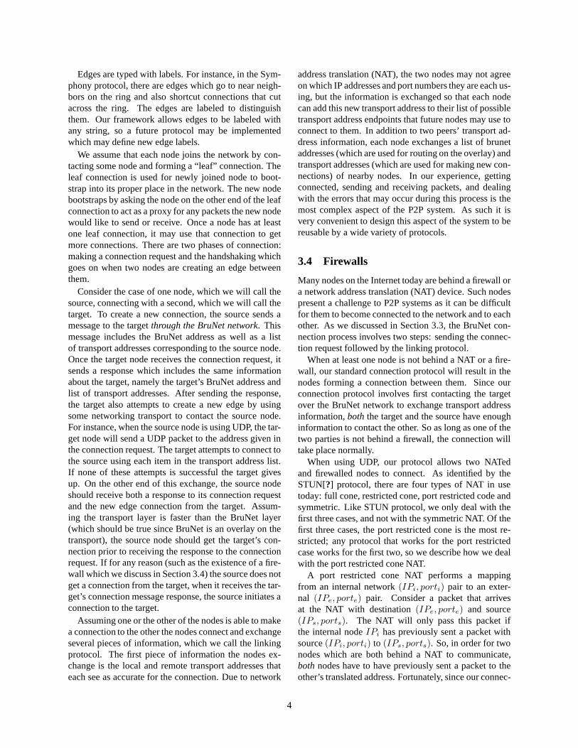
Figure 1: The structured ring permits efficient routingbetween nodes. This 200-node network was run on Plan-etLab.
protocol for supporting multi-attribute range queries thatlayers on top of a small-world-based ring; SWAN [17] isan implemented multi-agent system based on the original2-D Kleinberg model [5]. Of the aforementioned small-world P2P systems, only SWAN has been implemented,while performance estimates for Symphony, Accordion,and Mercury are based solely on simulations. Thereforethe presented system appears to be the first implemen-tation of the 1-D ring-based Kleinberg routable small-world network.
3 BruNet System Architecture
The BruNet P2P software framework is designed to al-low easy implementations of many different protocols.The software is implemented in theC# programminglanguage using the Mono compiler and virtual machineon GNU/Linux based systems. This section provides ageneral overview of the basic primitives of the system,namely nodes, addresses, edges, routers and connectionoverlords.
3.1 Nodes and Addressing
The active elements in the system are called nodes. Eachnode can send packets, receive packets, and route pack-ets. A particular computer system, such as a desktop PCor a server system may host one or more nodes. Thenode is envisioned as an agent for a user or softwareapplication. Each node has exactly one address, whichuniquely identifies that node on the network. Addition-ally, each node maintains several edges and uses theseedges to pass packets to neighboring nodes.
When a node is the destination of a packet, the nodeinforms the user, or a higher-layer software application,
2
of the packet. The node also acts as a manager of itsedges.
The 160-bit address space consists of all the integersfrom 0 to 2160 − 1 and is partitioned into 161 distinctaddress classes. To determine the class of a particularaddress, count the number of consecutive bits of value1on the rightmost part of the address. There can be be-tween 0 and 160, and thus there are 161 address classes.Clearly, address classn is twice as large asn + 1. Infact, a classn address ends with exactly one bit of value0 followed byn bits of value1 (except for class 160, forwhich all bits have the value1). The size of the classnaddress space is2159−n (except class 160, which has size1). To see that we have accounted for all the addresses,we can sum the size of each class and see that we get all2160 addresses:
S = 1 +
159∑
k=0
2159−k
= 1 + 2159(1 − 2−160
1 − 2−1)
= 1 + 2160 − 1 = 2160
So we see that if we count all classes from0 to 159 (andadd1 for class 160), we see that we get all2160 possibleaddresses.
Address class-0 is the largest. We use class-0 to rep-resent addresses on the ring. These “ring” addresses arecommon to both the Chord[9] and Symphony[3] proto-cols. We describe the routing algorithm for these ad-dresses in Section 4. In addition to the ring addresses inclass-0, we define class-124 as “directional” addresses.Directional addresses indicate that a packet should berouted in a particular direction on the ring such as clock-wise or counter-clockwise. Directional addresses areuseful for communicating with nearby nodes on the ringas is often needed when joining the network or in DHTapplications.
Our system is designed to be a general framework forP2P applications. For example, one application of oursystem might be to use class-1 addresses to represent hy-percube addresses such as those used in the Pastry P2Pprotocol [11]. This partitioning allows us to easily imple-ment new protocols without changing the packet formator core libraries.
3.2 Packet Format
All system packets begin with a byte that describes thetype of data contained in the payload, followed by apayload. The first packet type is0x01, which is usedby nodes to establish connections and discover one an-other’s BruNet system information.
Header Field Start Position Length (bytes)
Type 0 1Hops 1 2TTL 3 2Source 5 20Destination 25 20Payload Type 45 1
Table 1: Packet format
The second packet type is0x02, which is used forthe routed P2P protocols (this type is in contrast to type0x01 packets which are not routed on the overlay and areonly used when two nodes are directly connecting to oneanother). In many respects, the routed P2P packets aresimilar to Ethernet packets but with a few notable differ-ences. Ethernet has 8 byte addresses where this systemuses 20 byte addresses. Ethernet uses two bytes to denotethe payload type, where we use only one. Unlike Ether-net packets, we do not need to include a checksum (since,as we discuss in section 3.3, we assume that the edgesprovide accurate packets). Also unlike Ethernet, wedoneed to include a field to indicate how far the packet hastraveled and how far it is allowed to go.
Packets may encapsulate many different types of pay-loads. For instance, nodes manage their position in thenetwork by sending “network structure” packets to othernodes. Packets also transport what may be considered“application layer” data, such as queries for DHT or file-sharing applications.
3.3 Edges and Connectivity
In this work, we will say that a pair of nodes has anedge between them if they are communicating with oneanother by sending packets over a single overlay hop.Any underlying networking protocol which matches thisrequirement is a suitable transport. In fact, differentedges may work over different transport protocols (suchas TCP, UDP, etc.).
Every edge must provide two things:
• the edge must not pass corrupt packets
• the edge must know the length of each packet it re-ceives.
We identify endpoints of edges with transport ad-dresses, for instanceBruNet.tcp:192.168.0.1:10030toidentify an endpoint of a TCP edge at IP address192.168.0.1 and port 10030. Generally, the transport ad-dress is a pair which contains the protocol and the ad-dressing information for that protocol. Currently, we
3
have implemented TCP and UDP edges, but in princi-ple we could also define an Ethernet edge to transportBruNet over Ethernet.
Edges are typed with labels. For instance, in the Sym-phony protocol, there are edges which go to near neigh-bors on the ring and also shortcut connections that cutacross the ring. The edges are labeled to distinguishthem. Our framework allows edges to be labeled withany string, so a future protocol may be implementedwhich may define new edge labels.
We assume that each node joins the network by con-tacting some node and forming a “leaf” connection. Theleaf connection is used for a newly joined node to boot-strap into its proper place in the network. The new nodebootstraps by asking the node on the other end of theleaf connection to act as a proxy for any packets the newnode would like to send or receive. Once a node has atleast one leaf connection, it may use that connection toget more connections. There are two connection phases:making a connection request and the handshaking whichgoes on when two nodes are creating an edge betweenthem.
Consider the case of one node, which we will call thesource, connecting with a second, which we will call thetarget. To create a new connection, the source sends amessage to the targetthrough the BruNet network. Thismessage includes the BruNet address as well as a listof transport addresses corresponding to the source node.Once the target node receives the connection request, itsends a response which includes the same informationabout the target, namely the target’s BruNet address andlist of transport addresses. After sending the response,the target also attempts to create a new edge by usingsome networking transport to contact the source node.For instance, when the source node is using UDP, the tar-get node will send a UDP packet to the address given inthe connection request. The target attempts to connect tothe source using each item in the transport address list.If none of these attempts is successful the target givesup. On the other end of this exchange, the source nodeshould receive both a response to its connection requestand the new edge connection from the target. Assum-ing the transport layer is faster than the BruNet layer(which should be true since BruNet is an overlay on thetransport), the source node should get the target’s con-nection prior to receiving the response to the connectionrequest. If for any reason (such as the existence of a fire-wall which we discuss in Section 3.4) the source does notget a connection from the target, when it receives the tar-get’s connection message response, the source initiates aconnection to the target.
Assuming one or the other of the nodes is able tomake a connection to the other, the nodes connect and ex-change several pieces of information, which we call the
linking protocol. The first piece of information the nodesexchange is the local and remote transport addresses thateach see as accurate for the connection. Due to networkaddress translation (NAT), the two nodes may not agreeon which IP addresses and port numbers they are each us-ing, but the information is exchanged so that each nodecan add this new transport address to their list of possibletransport address endpoints that future nodes may use toconnect to them. In addition to two peers’ transport ad-dress information, each node exchanges a list of BruNetaddresses (which are used for routing on the overlay) andtransport addresses (which are used for making new con-nections) of nearby nodes. In our experience, gettingconnected, sending and receiving packets, and dealingwith the errors that may occur during this process is themost complex aspect of the P2P system. As such it isvery convenient to design this aspect of the system to bereusable by a wide variety of protocols.
3.4 Firewalls
Many nodes on the Internet today are behind a firewall ora network address translation (NAT) device. Such nodespresent a challenge to P2P systems as it can be difficultfor them to become connected to the network and to eachother. As we discussed in Section 3.3, the BruNet con-nection process involves two steps: sending the connec-tion request followed by the linking protocol.
When at least one node is not behind a NAT or a fire-wall, our standard connection protocol will result in thenodes forming a connection between them. Since ourconnection protocol involves first contacting the targetover the BruNet network to exchange transport addressinformation,both the target and the source have enoughinformation to contact the other. So as long as one of thetwo parties is not behind a firewall, the connection willtake place normally.
When using UDP, our protocol allows two NATedand firewalled nodes to connect. As identified by theSTUN[18] protocol, there are four types of NAT in usetoday: full cone, restricted cone, port restricted cone andsymmetric. Like the STUN protocol, we only deal withthe first three cases, and not with the symmetric NAT. Ofthe first three cases, the port restricted cone is the mostrestrictive; any protocol that works for the port restrictedcase works for the first two, so we describe how we dealwith the port restricted cone NAT.
A port restricted cone NAT performs a mappingfrom an internal network(IPi, porti) pair to an exter-nal (IPe, porte) pair. Consider a packet that arrivesat the NAT with destination(IPe, porte) and source(IPs, ports). The NAT will only pass this packet ifthe internal nodeIPi has previously sent a packet withsource(IPi, porti) to (IPs, ports). So, in order for two
4

nodes which are both behind a NAT to communicate,bothnodes have to have previously sent a packet to theother’s translated address. Fortunately, since our connec-tion protocol involves routing the transport address in-formation over the overlay, both nodes will get transportaddress information sufficient to contact the other. As-suming that both know their translated addresses, eachwill be send packets to the other’s translated addresses.If the NATs are not symmetric, they will pass all pack-ets after the first. Our linking protocol involves usingretries with back-off, thus the nodes will be able to sendthe necessary packets to open the connection through theNAT. The only issue that remains is how nodes learn theirtranslated transport address. As covered in Section 3.3,part of our protocol is for each node to echo the transportaddress information it sees to its peer during connection.This allows each node to learn its translated address as-suming it can make at least one leaf connection to a nodewhich is not behind a NAT.
Our approach uses the same facts about common NATdevices as the STUN protocol except we use the P2P net-work instead of a central server to share the translated IPinformation.
3.5 Routing and Connection Management
Most P2P systems will have a great deal of overlap inthe concepts we have discussed above, however signif-icant differences will emerge when it comes to routingof packets and the management of connections to peers.In the BruNet architecture, both routing and connectionmanagement are handled by components.
To implement a new protocol, most of the existingBruNet system is reused, but a new router object mustbe defined and associated with the address class that willbe used for that protocol. Additionally, each P2P pro-tocol may have different rules for maintaining connec-tions to peers including how many connections to main-tain and to which peer each node should be connected.Connection overlord objects encapsulate the code whichmanages the connections in the system. For instance, inthe Symphony protocol, each node should have a con-nection to its left and right neighbors as well as at leastone shortcut connection. We implemented aSymphony-ConnectionOverlordwhich counts the number of eachof these types of connections, initiates new connectionswhen needed, and closes connections that are no longerneeded.
BruNet was designed to implement unstructured aswell as structured P2P protocols. Implementing unstruc-tured protocols, such as the Gnutella broadcast queryprotocol, is also easy. One need only define a new ad-dress class to represent broadcasts, implement a router tohandle the routing of the broadcast messages and to build
a routing table of known addresses, and finally a connec-tion overlord that makes sure that the node stays con-nected to the network as nodes come and go. The con-nection logic, transport abstraction, packetization, andserialization can all be reused between various imple-mentations.
4 An Implementation of Symphony
In the previous section we discussed the architecture ofthe BruNet P2P framework. In this section we describeour implementation of the Symphony 1-D small-worldsystem. To implement a particular P2P system, we needto describe the routing and connection management, in-cluding joining and leaving, which we discuss in Sec-tions 4.1 and 4.2 respectively.
We use class-0 addresses for this protocol. Thus, eachnode in the network can take one of2159 structured ad-dresses1. We interpret these addresses as even 160-bitintegers in the range[0, 2160 − 2] with this address spaceforming a ring. By convention, we say that the ringin-creasesin theclockwisedirection.
4.1 Small World Routing
The theory that supports structured routing comes fromworks on routable small-worlds [4, 5]. However, we in-troduce novel practical routing algorithms, which makenetwork maintenance a natural consequence of thoserouting algorithms. As we discuss in Section 3.1, eachnode has an address that can be interpreted as a coor-dinate on a ring. As such, there is directionality (e.g.clockwise and counterclockwise). There are two mecha-nisms for routing on this structure: destination based anddirection based.
In direction based routing, we use fixed addresses(class-124) to refer to “clockwise” and “counterclock-wise”. When the packet’s HOPS equal its TTL, thepacket is delivered. By setting the TTL, a node canthen communicate with its near-neighbors on the ring.This might have interesting applications for caching inDHT systems. Nodes maintain connections to at leasttwo nearest nodes to them in both directions. This di-rection based routing is what enables a node to find itsnear-neighbors in order to connect to them.
Destination based routing is slightly more complex.This mode of routing refers to the case where one nodewants to address a second node by that second node’sclass-0 address, not based on its relative position on thering. The simplest approach would be to route to theneighbor node which is closest to the destination, never
1for randomly selected addresses, the network size will haveto be≈ 2
79 nodes before we are likely to reuse an address
5
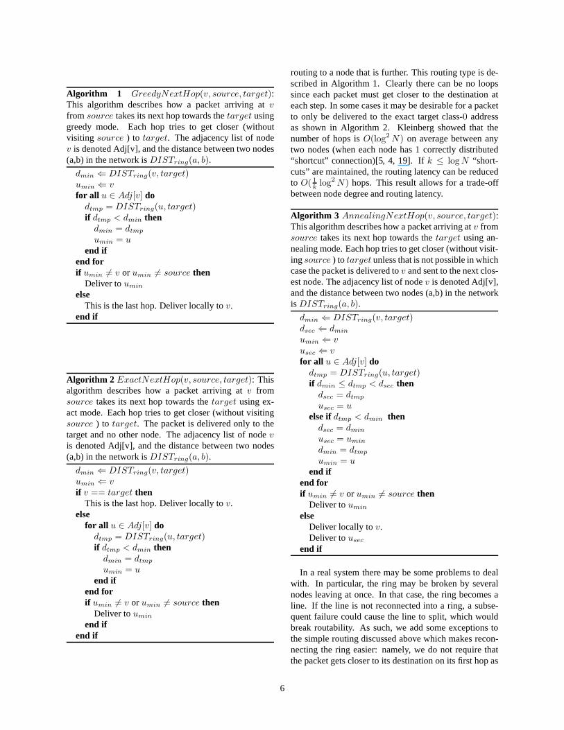
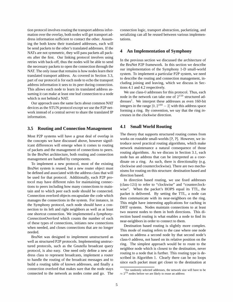
Algorithm 1 GreedyNextHop(v, source, target):This algorithm describes how a packet arriving atvfrom source takes its next hop towards thetarget usinggreedy mode. Each hop tries to get closer (withoutvisiting source ) to target. The adjacency list of nodev is denoted Adj[v], and the distance between two nodes(a,b) in the network isDISTring(a, b).
dmin ⇐ DISTring(v, target)umin ⇐ vfor all u ∈ Adj[v] do
dtmp = DISTring(u, target)if dtmp < dmin then
dmin = dtmp
umin = uend if
end forif umin 6= v or umin 6= source then
Deliver toumin
elseThis is the last hop. Deliver locally tov.
end if
Algorithm 2 ExactNextHop(v, source, target): Thisalgorithm describes how a packet arriving atv fromsource takes its next hop towards thetarget using ex-act mode. Each hop tries to get closer (without visitingsource ) to target. The packet is delivered only to thetarget and no other node. The adjacency list of nodevis denoted Adj[v], and the distance between two nodes(a,b) in the network isDISTring(a, b).
dmin ⇐ DISTring(v, target)umin ⇐ vif v == target then
This is the last hop. Deliver locally tov.else
for all u ∈ Adj[v] dodtmp = DISTring(u, target)if dtmp < dmin then
dmin = dtmp
umin = uend if
end forif umin 6= v or umin 6= source then
Deliver toumin
end ifend if
routing to a node that is further. This routing type is de-scribed in Algorithm 1. Clearly there can be no loopssince each packet must get closer to the destination ateach step. In some cases it may be desirable for a packetto only be delivered to the exact target class-0 addressas shown in Algorithm 2. Kleinberg showed that thenumber of hops isO(log2 N) on average between anytwo nodes (when each node has1 correctly distributed“shortcut” connection)[5, 4, 19]. Ifk ≤ log N “short-cuts” are maintained, the routing latency can be reducedto O( 1
klog2 N) hops. This result allows for a trade-off
between node degree and routing latency.
Algorithm 3 AnnealingNextHop(v, source, target):This algorithm describes how a packet arriving atv fromsource takes its next hop towards thetarget using an-nealing mode. Each hop tries to get closer (without visit-ingsource ) to target unless that is not possible in whichcase the packet is delivered tov and sent to the next clos-est node. The adjacency list of nodev is denoted Adj[v],and the distance between two nodes (a,b) in the networkis DISTring(a, b).
dmin ⇐ DISTring(v, target)dsec ⇐ dmin
umin ⇐ vusec ⇐ vfor all u ∈ Adj[v] do
dtmp = DISTring(u, target)if dmin ≤ dtmp < dsec then
dsec = dtmp
usec = uelse ifdtmp < dmin then
dsec = dmin
usec = umin
dmin = dtmp
umin = uend if
end forif umin 6= v or umin 6= source then
Deliver toumin
elseDeliver locally tov.Deliver tousec
end if
In a real system there may be some problems to dealwith. In particular, the ring may be broken by severalnodes leaving at once. In that case, the ring becomes aline. If the line is not reconnected into a ring, a subse-quent failure could cause the line to split, which wouldbreak routability. As such, we add some exceptions tothe simple routing discussed above which makes recon-necting the ring easier: namely, we do not require thatthe packet gets closer to its destination on its first hop as
6

described in Algorithm 3.
4.2 Joining the Small-World
In order for a node to join the ring, it makes use of Rout-ing Algorithm 3: annealing routing. The annealing rout-ing tolerates some disorder in the network. Every nodethat joins the ring must have a 160-bit class-0 address.This address must be randomly-generated to ensure thenear uniform distribution of addresses on the ring; thusclass-0 addresses are obtained by using a secure hash al-gorithm or some other source of random bits. After anode has a class-0 address, it must find its place in thering. This means that it needs to make a connection tothe closest node on both the right and left of its own ad-dress. Since the new node is not yet connected to the cor-rect place in the ring it is not yet able to route messagesusing the routing algorithms described above. The newnode instead makes use of a node that is correctly placedin the ring as a proxy in order to find its place. The newnode creates a special type of bootstrapping connectionthat does not support any of the routing algorithms abovebut does provide for packets to be sent to the node on theother end of the connection. This bootstrapping connec-tion allows the new node to communicate with the proxyin order to send and receive messages while it is waitingto find its place in the ring. The proxy sends a requestto connect to the new address which is not yet in the net-work. Given the new node’s absence, the closest nodeon the right and the closest node on left of the new nodewill form connections to the new joining node. At thispoint the new node is at the correct location in the ringand can add additional neighbors and shortcut connec-tions as needed. Algorithm 4 shows this process.
Connection is not an instantaneous process. Our im-plementation uses two round trips: a link request andresponse, and a status request and response. The linkmessages exchange the node addresses, the IP addressesand port numbers, and whether the connection is a near-neighbor connection or shortcut connection. The statusmessage allows the nodes to communicate some of theirproperties to their neighbors. In particular, the statusmessage shares the node address and IP information ofother nodes which are close to the new neighbor. Thisinformation allows nodes to verify that their views of thenetwork are consistent and make repairs.
In addition to neighbor connections, every node mustalso maintaink shortcut connections to other nodes thatare far away in the address space. Specifically, the dis-tances traveled by all the shortcut connections in thestructured ring must follow a probability distributionfunction (pdf) of the following form:p(d) ∝ 1/d, whered denotes the distance traveled by the shortcut connec-tion [4, 5]. We use the local density of addresses to es-
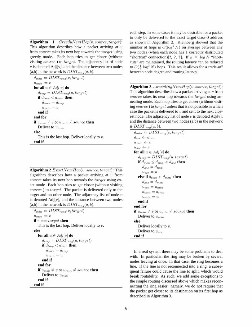
Algorithm 4 JoiningTheRing(v, u): This algorithmdescribes how a new node, denoted asv, joins the struc-tured ring. The proxy that helpsv find its place in thenetwork is calledu. The class-0 address of a node is de-noted asADD(node). ADD(vc) is the closest addressto ADD(v). PREV (vc, v) is the closest neighbor ofvc
in the direction ofv.v makes a proxy connection to nodeu.v sends a connection request throughu to ADD(v).u sends a connection request toADD(v).vc receives the request and connects tov.v sends a connection request toPREV (vc, v).PREV (vc, v) connects tov.v is now in the correct ring location.
timate network size and thusdave, the average distancebetween nodes. Then, we choose a random distancedbetweendave anddmax = 2160 with probability propor-tional to1/d and connect to the node closest to that ad-dress using Routing Algorithm 1 (greedy routing). Themethod we use to select a proper distance is to define arandom variablex distributed uniformly over[0, 1], andset:
d = dave
(
dmax
dave
)x
.
From the above, we see that:
Prob(d ≤ L) = Prob
(
x ≤log L/dave
log dmax/dave
)
which is clearly the CDF for the random variabled to bedistributed proportional to1/d over (dave, dmax). Thisis repeatedk times. The total cost in packets to join thenetwork isO(log2 N), since we need to sendO(k) pack-ets and each packet requiresO( 1
klog2 N) hops.
5 PlanetLab Experiments
This section describes the results of the reliability testsofthe BruNet software. All of the experimental results onour implementation are performed using the global Plan-etLab test-bed. PlanetLab provides a realistic, WAN en-vironment to test distributed applications. In fact, Plan-etLab nodes are often highly loaded and represent a verychallenging test environment.
5.1 Experimental Methodology
PlanetLab gives access to around 400 computers that arelocated in many countries around the world. There aredozens of research projects running simultaneously onthe scarce computational resources provided by Planet-Lab. As a result, PlanetLab provides a measure of appli-cation performance on very adverse computational and
7

1
0.5
01.0 x 1046 3.4 x 1047 6.7 x 1047
CD
F(d
)
d
CDF(d)log(d) fit
Figure 2: The 1-D Kleinberg small-world structure re-quires that the distances of the shortcut connections havea pdfp(d) ∝ 1/d. In this PlanetLab experiment, we seethat the cdf(d) follows the expected logarithmic distribu-tion for a network of size 1060.
traffic load conditions. For the experiments presented inthis section, around 100 PlanetLab machines were em-ployed.
The current implementation is in C# using the Monodevelopment platform. In order to minimize memory andother computational resource usage on PlanetLab ma-chines, we run multiple nodes inside a single Mono run-time process. As a result, many nodes can reside on asingle machine. However, each node is executed on aseparate thread and maintains its own connections anddata. Furthermore since class-0 addresses are assignedrandomly, nodes that reside on the same physical ma-chine are unlikely to be close to each other on the ad-dress space. We note that the UDP transport is used forall experiments presented in this section2.
In our experiments, we wish to see that the structure ofthe network is correct, that the system can indeed routepackets, and that the system is robust to node arrivals andfailures. We analyze the logs of our experiments witha software tool which shares no code with the BruNetsystem itself. The metric we use to measure the robust-ness of the network is routability. Routability of the net-work is defined as the fraction of pairs of nodes whichcan communicate using the standard (in this case greedy)routing algorithm.
5.2 Structure Verification
As discussed in Sections 3.1 and 4, all nodes are iden-tified by unique 160-bit addresses, which can be inter-preted as integers; nodes are arranged in a ring, with the
2We have verified that the system on a TCP transport delivers com-parable performance to UDP.
convention that the integer representation of the node ad-dresses increase in the clockwise direction. Furthermore,our structured small-world routing network requires thateach node keeps two neighbor connections to two closestclass-0 addresses in the clockwise direction and counter-clockwise direction. In other words, the structured ringis correct if and only if the following is true: every nodehas connections to its first and second class-0 neighborson the clockwise and the counterclockwise directions inthe address space.
We have successfully deployed a correct structuredring of size 1060 nodes on PlanetLab. It is difficult tosee much in visualizations of such large graphs, howeverwe present several figures for various sized networks inFigure 1 and Figures 9-11.
We verified the correctness of the shortcut distancedistribution by conducting the following: after the de-ployment of a correct 1060-node structured ring, all theshortcut connection distances are extracted from the ex-periment logs. The cumulative distribution function (cdf)of the shortcut distances is plotted in Figure 2. Note thatthe experimental cdf curve is in good agreement with theexpected curve:cdf(d) ∝ log(d).
5.3 Churn
Nodes do not stay in a P2P network indefinitely. One ofthe most striking aspects of the P2P network paradigm isthat we assume that nodes are fundamentally faulty andwill join and leave a network unexpectedly. Any real sys-tem must deal with unexpected arrivals and departures,which is called churn.
A major question is: will a node complete the joiningprocess correctly, in the presence of a slightly disorderednetwork, before the node departs. There are two impor-tant time scales in the churn process: the mean round-trip-time (RTT) between the hosts at the IP layer, and themean session time of the node. As the session time ap-proaches the RTT, clearly the system will not work prop-erly. Since each node requires two neighbor connectionsand at least one shortcut connection, the time required toestablish the node will be much greater than the RTT.
In our experiment, we created a correct network of 980nodes on PlanetLab. Once the network was correct, wethen started the system churning for 25 minutes. Eachsecond, with a fixed probability, every node abruptlygoes offline, and then rejoins the network. This corre-sponds to an exponential distribution on session time.
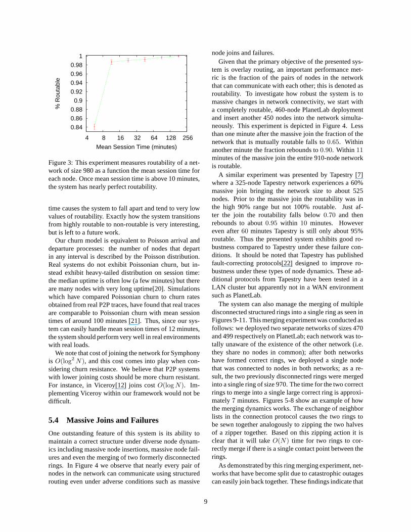
Figure 3 shows the results of our experiment. Wefind that when mean session time is above 12 minutes,the system is more than99% routable, however as meansession time decreases to 5.7 minutes, we find that thesystem becomes significantly more disordered with aroutability of 84%. Further decreasing the mean session
8
0.84
0.86
0.88
0.9
0.92
0.94
0.96
0.98
1
4 8 16 32 64 128 256
% R
outa
ble
Mean Session Time (minutes)
Figure 3: This experiment measures routability of a net-work of size 980 as a function the mean session time foreach node. Once mean session time is above 10 minutes,the system has nearly perfect routability.
time causes the system to fall apart and tend to very lowvalues of routability. Exactly how the system transitionsfrom highly routable to non-routable is very interesting,but is left to a future work.
Our churn model is equivalent to Poisson arrival anddeparture processes: the number of nodes that departin any interval is described by the Poisson distribution.Real systems do not exhibit Poissonian churn, but in-stead exhibit heavy-tailed distribution on session time:the median uptime is often low (a few minutes) but thereare many nodes with very long uptime[20]. Simulationswhich have compared Poissonian churn to churn ratesobtained from real P2P traces, have found that real tracesare comparable to Poissonian churn with mean sessiontimes of around 100 minutes [21]. Thus, since our sys-tem can easily handle mean session times of 12 minutes,the system should perform very well in real environmentswith real loads.
We note that cost of joining the network for Symphonyis O(log2 N), and this cost comes into play when con-sidering churn resistance. We believe that P2P systemswith lower joining costs should be more churn resistant.For instance, in Viceroy[12] joins costO(log N). Im-plementing Viceroy within our framework would not bedifficult.
5.4 Massive Joins and Failures
One outstanding feature of this system is its ability tomaintain a correct structure under diverse node dynam-ics including massive node insertions, massive node fail-ures and even the merging of two formerly disconnectedrings. In Figure 4 we observe that nearly every pair ofnodes in the network can communicate using structuredrouting even under adverse conditions such as massive
node joins and failures.Given that the primary objective of the presented sys-
tem is overlay routing, an important performance met-ric is the fraction of the pairs of nodes in the networkthat can communicate with each other; this is denoted asroutability. To investigate how robust the system is tomassive changes in network connectivity, we start witha completely routable, 460-node PlanetLab deploymentand insert another 450 nodes into the network simulta-neously. This experiment is depicted in Figure 4. Lessthan one minute after the massive join the fraction of thenetwork that is mutually routable falls to0.65. Withinanother minute the fraction rebounds to0.90. Within 11minutes of the massive join the entire 910-node networkis routable.
A similar experiment was presented by Tapestry [7]where a 325-node Tapestry network experiences a 60%massive join bringing the network size to about 525nodes. Prior to the massive join the routability was inthe high 90% range but not 100% routable. Just af-ter the join the routability falls below0.70 and thenrebounds to about0.95 within 10 minutes. Howevereven after60 minutes Tapestry is still only about 95%routable. Thus the presented system exhibits good ro-bustness compared to Tapestry under these failure con-ditions. It should be noted that Tapestry has publishedfault-correcting protocols[22] designed to improve ro-bustness under these types of node dynamics. These ad-ditional protocols from Tapestry have been tested in aLAN cluster but apparently not in a WAN environmentsuch as PlanetLab.
The system can also manage the merging of multipledisconnected structured rings into a single ring as seen inFigures 9-11. This merging experiment was conducted asfollows: we deployed two separate networks of sizes 470and 499 respectively on PlanetLab; each network was to-tally unaware of the existence of the other network (i.e.they share no nodes in common); after both networkshave formed correct rings, we deployed a single nodethat was connected to nodes in both networks; as a re-sult, the two previously disconnected rings were mergedinto a single ring of size 970. The time for the two correctrings to merge into a single large correct ring is approxi-mately7 minutes. Figures 5-8 show an example of howthe merging dynamics works. The exchange of neighborlists in the connection protocol causes the two rings tobe sewn together analogously to zipping the two halvesof a zipper together. Based on this zipping action it isclear that it will takeO(N) time for two rings to cor-rectly merge if there is a single contact point between therings.
As demonstrated by this ring merging experiment, net-works that have become split due to catastrophic outagescan easily join back together. These findings indicate that
9

1e-04 0.001
0.01 0.1
1
0 20 40 60 80 100 120
Time (minutes)
% Missing Edges
0 0.2 0.4 0.6 0.8
1
% Correct Routes
0
250
500
750
1000
N
450-NodeMassive Join
450-NodeMassive Failure
Figure 4: The network is very robust during gradual joins, massive joins and massive failures of nodes. After abruptchanges in connectivity, the network structure heals back to a perfect ring very rapidly and achieves overwhelmingpercentage routability long before the ring is completely correct. This demonstrates the applicability of the system tohighly dynamic applications. Moreover, from examining thebottommost figure, one can observe that the number ofmissing edges in the network decreases exponentially fast in time after the massive join of 450 nodes.
A
B
C
D
Ring 1
Ring 2
E
Figure 5: Two distinctroutable rings denoted asRing 1 and Ring 2 canbe merged into a largeroutable ring. Here we de-pict Ring 1 merging withRing 2.
A
B DE
C
Figure 6: ”C” connects to”B” and ”D”, the two clos-est nodes on Ring 2. As anormal part of the connec-tion protocol, ”C” sends itneighbor lists to ”B” and”D”.
A
B DE
C
Figure 7: Based on theneighbor-list informationobtained from ”C” whileconnecting, ”B” connectsto ”A” and ”D” connectsto ”E”.
A
B DE
C
Figure 8: The network isnow correctly ordered butthere are many more con-nections than are needed.Each node maintainskconnections to the closestneighbors on the right andleft (k = 1 in this exam-ple). Each node will trimthe excess connections un-til only the k closest oneach side remain.
10
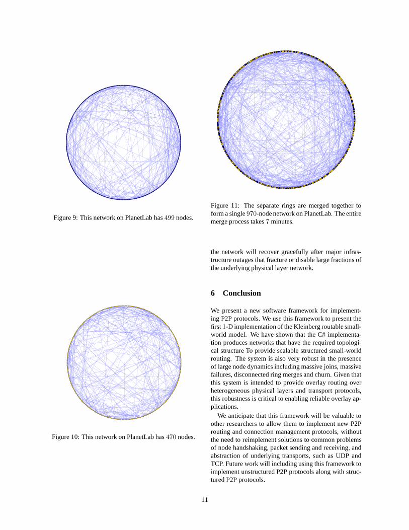
Figure 9: This network on PlanetLab has499 nodes.
Figure 10: This network on PlanetLab has470 nodes.
Figure 11: The separate rings are merged together toform a single970-node network on PlanetLab. The entiremerge process takes7 minutes.
the network will recover gracefully after major infras-tructure outages that fracture or disable large fractions ofthe underlying physical layer network.
6 Conclusion
We present a new software framework for implement-ing P2P protocols. We use this framework to present thefirst 1-D implementation of the Kleinberg routable small-world model. We have shown that the C# implementa-tion produces networks that have the required topologi-cal structure To provide scalable structured small-worldrouting. The system is also very robust in the presenceof large node dynamics including massive joins, massivefailures, disconnected ring merges and churn. Given thatthis system is intended to provide overlay routing overheterogeneous physical layers and transport protocols,this robustness is critical to enabling reliable overlay ap-plications.
We anticipate that this framework will be valuable toother researchers to allow them to implement new P2Prouting and connection management protocols, withoutthe need to reimplement solutions to common problemsof node handshaking, packet sending and receiving, andabstraction of underlying transports, such as UDP andTCP. Future work will including using this framework toimplement unstructured P2P protocols along with struc-tured P2P protocols.
11
7 Acknowledgements
We would like to thank Nikolas Kontorinis and JulieWalters for many helpful comments.
References
[1] S. Saroiu, K. P. Gummadi, R. Dunn, S. D.Gribble, and H. M. Levy, “An analysis of In-ternet content delivery systems,” inProceedingsof the Fifth Symposium on Operating SystemsDesign and Implementation (OSDI 2002), Boston,MA, December 2002. [Online]. Available: cite-seer.ist.psu.edu/article/saroiu02analysis.html
[2] J. Risson and T. Moors, “Survey of research to-wards robust peer-to-peer networks: Search meth-ods,” University of New South Wales, Sydney, Aus-tralia, Tech. Rep. UNSW-EE-P2P-1-1, 2004.
[3] G. S. Manku, M. Bawa, and P. Raghavan,“Symphony: Distributed hashing in a smallworld,” Proc. 4th USENIX Symposium onInternet Technologies and Systems, pp. 127–140,2003. [Online]. Available: http://www-db.stanford.edu/ manku/papers/03usits-symphony.pdf
[4] J. Kleinberg, “Navigation in a small world,”Nature, vol. 406, p. 845, 2000. [Online]. Available:http://www.cs.cornell.edu/home/kleinber/nat00.pdf
[5] ——, “The Small-World Phenomenon: AnAlgorithmic Perspective,” in Proceedings ofthe 32nd ACM Symposium on Theory ofComputing, 2000. [Online]. Available: cite-seer.ist.psu.edu/kleinberg00smallworld.html
[6] P. Maymounkov and D. Mazieres, “Kademlia: Apeer-to-peer information system based on the xormetric,” in IPTPS ’01: Revised Papers from theFirst International Workshop on Peer-to-Peer Sys-tems. London, UK: Springer-Verlag, 2002, pp.53–65.
[7] B. Y. Zhao, L. Huang, S. C. Rhea, J. Stribling,A. D. Joseph, and J. D. Kubiatowicz, “Tapestry: Aglobal-scale overlay for rapid service deployment,”IEEE J-SAC, vol. 22, no. 1, pp. 41–53, January2004.
[8] I. Stoica, R. Morris, D. Karger, F. Kaashoek, andH. Balakrishnan, “Chord: A scalable peer-to-peerlookup service for Internet applications,” inACMSIGCOMM, August 2001, pp. 149–160.
[9] I. Stoica, R. Morris, D. Liben-Nowell, D. R.Karger, M. F. Kaashoek, F. Dabek, and H. Balakr-ishnan, “Chord: a scalable peer-to-peer lookup pro-tocol for internet applications,”IEEE/ACM Trans.Netw., vol. 11, no. 1, pp. 17–32, 2003.
[10] S. Ratnasamy, P. Francis, M. Handley, R. Karp,and S. Shenker, “A scalable content address-able network,” in Proceedings of ACM SIG-COMM 2001, 2001. [Online]. Available: cite-seer.ist.psu.edu/ratnasamy01scalable.html
[11] A. I. T. Rowstron and P. Druschel, “Pastry: Scal-able, decentralized object location, and routing forlarge-scale peer-to-peer systems,” inProceedingsof the IFIP/ACM International Conference on Dis-tributed Systems Platforms Heidelberg. Springer-Verlag, 2001, pp. 329–350.
[12] D. Malkhi, M. Naor, and D. Ratajczak, “Viceroy: ascalable and dynamic emulation of the butterfly,” inPODC ’02: Proceedings of the twenty-first annualsymposium on Principles of distributed computing.New York, NY, USA: ACM Press, 2002, pp. 183–192.
[13] N. J. A. Harvey and J. I. Munro, “DeterministicSkipNet,” Inf. Process. Lett., vol. 90, no. 4, pp.205–208, 2004.
[14] S. Rhea, D. Geels, T. Roscoe, and J. Kubiatowicz,“Handling Churn in a DHT,” inProceedings of the2004 USENIX Technical Conference, June 2004.
[15] J. Li, J. Stribling, R. Morris, and M. F. Kaashoek,“Bandwidth-efficient management of DHT routingtables,” inProc. of the 2nd NSDI, May 2005.
[16] A. R. Bharambe, M. Agrawal, and S. Seshan, “Mer-cury: supporting scalable multi-attribute rangequeries,” inSIGCOMM ’04: Proceedings of the2004 conference on Applications, technologies, ar-chitectures, and protocols for computer communi-cations. New York, NY, USA: ACM Press, 2004,pp. 353–366.
[17] E. Bonsma and C. Hoile, “A distributed implemen-tation of the SWAN peer-to-peer look-up systemusing mobile agents,”Lecture Notes in ComputerScience, vol. 2530, pp. 100 – 111, 2003.
[18] J. Rosenberg, J. Weinberger, C. Huitema, andR. Mahy, “STUN - simple traversal of user data-gram protocol (UDP) through network addresstranslators (NATs),” IETF, Tech. Rep., rfc3489.
[19] J. Kleinberg, “Small-world phenomena and the dy-namics of information,” 2001. [Online]. Available:citeseer.ist.psu.edu/kleinberg01smallworld.html
12
[20] S. Rhea, D. Geels, T. Roscoe, and J. Kubiatow-icz, “Handling churn in a DHT,” inProceedingsof the 2004 USENIX Annual Technical Conference(USENIX ’04), Boston, Massachusetts, June 2004.
[21] M. Castro, M. Costa, and A. Rowstron, “Perfor-mance and dependability of structured peer-to-peeroverlays,” in DSN ’04: Proceedings of the 2004International Conference on Dependable Systemsand Networks (DSN’04). Washington, DC, USA:IEEE Computer Society, 2004, p. 9.
[22] B. Y. Zhao, L. Huang, J. Stribling, A. D. Joseph,and J. D. Kubiatowicz, “Exploiting routing re-dundancy via structured peer-to-peer overlays,” inProc. of ICNP. Atlanta, GA: IEEE, Nov 2003, pp.246–257.
13
arX
iv:0
709.
4048
v1 [
cs.D
C]
25 S
ep 2
007
A Symphony Conducted by BruNetP. Oscar Boykin
Department of Electrical and Computer EngineeringUniversity of Florida
Jesse S. A. BridgewaterElectrical Engineering Department
University of California, Los Angeles
Joseph S. KongElectrical Engineering Department
University of California, Los Angeles
Kamen M. LozevElectrical Engineering Department
University of California, Los Angeles
Behnam A. RezaeiElectrical Engineering Department
University of California, Los Angeles
Vwani P. RoychowdhuryElectrical Engineering Department
University of California, Los Angeles
Abstract
We introduce BruNet, a general P2P software frame-work which we use to produce the first implementationof Symphony, a 1-D Kleinberg small-world architecture.Our framework is designed to easily implement and mea-sure different P2P protocols over different transport lay-ers such as TCP or UDP. This paper discusses our im-plementation of the Symphony network, which allowseach node to keepk ≤ log N shortcut connections andto route to any other node with a short average delayof O( 1
klog2 N). We present experimental results taken
from several PlanetLab deployments of size up to 1060nodes. These successful deployments represent some ofthe largest PlanetLab deployments of P2P overlays foundin the literature, and show our implementation’s robust-ness to massive node dynamics in a WAN environment.
1 Introduction: Motivation and Summaryof Results
Peer-To-Peer (P2P) networking is an increasingly pop-ular network model where nodes communicate directlywithout utilizing a centralized server. In recent years,P2P file-sharing applications have flourished. A recentstudy shows that P2P systems are responsible for ap-proximately one half of the network traffic at a majoruniversity[?] and comprise a significant fraction of totalInternet traffic. For a review of P2P search systems, see[?].
There are three novel contributions reported in thiswork. First, we describe a new P2P software frameworkcalled BruNet. The BruNet framework handles most ofthe issues common to all P2P protocols such as dealingwith firewalls and NATs, connecting nodes, and routingpackets. Secondly, we use the BruNet P2P frameworkto implement Symphony[?], a 1-D Kleinberg routablesmall-world network[?, ?]. This is the first implemen-tation of a 1-D routable small-world network. Third, we
report on large scale PlanetLab tests involving more than1000 nodes, which puts the P2P networks described hereamongst the largest P2P networks to be tested on Planet-Lab.
Our BruNet software architecture manages P2P packetrouting and connection maintenance. Given a packetwith a particular destination addressA, the system willdeliver the packet to the node closest to that address.This sort of routing primitive may be used to build a dis-tributed hash table (DHT), which is common in the P2Pliterature. Clearly, the success and efficacy of such anad-hoc addressing and routing scheme depends on therobustness of the overlay structured networks.
The deployment of DHT P2P systems such as theKademlia-based[?] eDonkey, which already supportsabout a million simultaneous users, indicates that large-scale overlay networks are feasible. The existence ofsuch large-scale DHT systems is impressive, howeverthe performance of P2P networks at that scale has notyet been systematically studied. While we have not yetscaled to one million nodes, our experiments of morethan 1,000 nodes is amongst largest P2P networks to betested on PlanetLab. The data we obtained from deploy-ments of our system on PlanetLab show that the struc-tured routing network can indeed be bootstrapped froma random initial network, and can be robust to high ratesof joins and departures of participating nodes.
We chose Symphony, the 1-D Kleinberg routablesmall-world network[?, ?, ?] as the topology for thestructured overlay network. This ringlike address spaceentails simple routing calculations and requires very lownode state. Our structured overlay is currently the onlyimplementation of a 1-D Kleinberg routable small-worldnetwork; as reviewed in the next section, a number ofschemes that utilize the 1-D small-world model havebeen proposed, but to the best knowledge of the au-thors none have been deployed and tested in a WANenvironment. Kleinberg proved that properly designedsmall-world networks could support efficient decentral-
1
ized routing withO(log2N) latency. The proposed sys-tem uses a 160-bit address space to construct a ringlikestructure. Shortcuts are made in this ringlike addressspace according to a specific probability distribution[?].The analysis and simulation results in [?] show thatmaintainingk ≤ log N long-range neighbors improvesrouting latency toO( 1
klog2 N).
Our functioning implementation adds several new fea-tures to the routable small-world model, including ex-panded routing rules to permit firewall traversal and easybootstrapping and also to obtain a structured 1-D ringstarting from any initially connected network. Networksup to 1060 nodes have been deployed on PlanetLab, aswe discuss later in Section 5. A key goal of this effortis that the network remains routable in the presence ofmassive node dynamics including massive joins, massivefailures, ring merging and churn. The system’s robust-ness under heavy node dynamics compares very favor-ably to the results published for Tapestry[?]; moreover,our deployment has more than twice the number of nodesdealt with in [?].
The paper is laid out as follows: we first discuss re-lated work in the following section. Section 3 describesthe BruNet software architecture and system compo-nents. Section 3 also includes our approach to travers-ing firewalls and NAT devices. Section 4 provides de-tails on our Symphony implementation. Finally, Section5 presents PlanetLab experiments that demonstrate thecorrectness and robustness of the network.
2 Related Work
There has been much recent work on producing struc-tured P2P overlays with distributed hash table (DHT) in-terfaces. Some examples of these structured systems in-clude [?, ?, ?, ?, ?, ?, ?, ?, ?, ?]. The main advantages ofthese structured DHT systems are scalable object loca-tion in O(log N) or O(log2 N) steps and the guaranteedretrieval of any existing object.
This paper reports on an implementation and measure-ments rather than simulation of a P2P network. Whilethere are many reports of simulations of structured P2Pprotocols, the measurement of such protocols in realworld WAN environments has rarely been addressed(e.g. [?]).
Among the existing structured systems, there are sev-eral Kleinberg-inspired small-world P2P overlays: Sym-phony [?] provides a detailed software design for a DHTsystem based on a unit-circumference ring; Accordion[?] is a proposed small-world-based structured systemdesigned to provide efficient bandwidth management ofthe distributed routing tables; Mercury [?] presents aprotocol for supporting multi-attribute range queries thatlayers on top of a small-world-based ring; SWAN [?] is
Figure 1: The structured ring permits efficient routingbetween nodes. This 200-node network was run on Plan-etLab.
an implemented multi-agent system based on the original2-D Kleinberg model [?]. Of the aforementioned small-world P2P systems, only SWAN has been implemented,while performance estimates for Symphony, Accordion,and Mercury are based solely on simulations. Thereforethe presented system appears to be the first implemen-tation of the 1-D ring-based Kleinberg routable small-world network.
3 BruNet System Architecture
The BruNet P2P software framework is designed to al-low easy implementations of many different protocols.The software is implemented in theC# programminglanguage using the Mono compiler and virtual machineon GNU/Linux based systems. This section provides ageneral overview of the basic primitives of the system,namely nodes, addresses, edges, routers and connectionoverlords.
3.1 Nodes and Addressing
The active elements in the system are called nodes. Eachnode can send packets, receive packets, and route pack-ets. A particular computer system, such as a desktop PCor a server system may host one or more nodes. Thenode is envisioned as an agent for a user or softwareapplication. Each node has exactly one address, whichuniquely identifies that node on the network. Addition-ally, each node maintains several edges and uses theseedges to pass packets to neighboring nodes.
When a node is the destination of a packet, the nodeinforms the user, or a higher-layer software application,of the packet. The node also acts as a manager of itsedges.
2
The 160-bit address space consists of all the integersfrom 0 to 2160 − 1 and is partitioned into 161 distinctaddress classes. To determine the class of a particularaddress, count the number of consecutive bits of value1on the rightmost part of the address. There can be be-tween 0 and 160, and thus there are 161 address classes.Clearly, address classn is twice as large asn + 1. Infact, a classn address ends with exactly one bit of value0 followed byn bits of value1 (except for class 160, forwhich all bits have the value1). The size of the classnaddress space is2159−n (except class 160, which has size1). To see that we have accounted for all the addresses,we can sum the size of each class and see that we get all2160 addresses:
S = 1 +
159∑
k=0
2159−k
= 1 + 2159(1 − 2−160
1 − 2−1)
= 1 + 2160 − 1 = 2160
So we see that if we count all classes from0 to 159 (andadd1 for class 160), we see that we get all2160 possibleaddresses.
Address class-0 is the largest. We use class-0 to rep-resent addresses on the ring. These “ring” addresses arecommon to both the Chord[?] and Symphony[?] proto-cols. We describe the routing algorithm for these ad-dresses in Section 4. In addition to the ring addresses inclass-0, we define class-124 as “directional” addresses.Directional addresses indicate that a packet should berouted in a particular direction on the ring such as clock-wise or counter-clockwise. Directional addresses areuseful for communicating with nearby nodes on the ringas is often needed when joining the network or in DHTapplications.
Our system is designed to be a general framework forP2P applications. For example, one application of oursystem might be to use class-1 addresses to represent hy-percube addresses such as those used in the Pastry P2Pprotocol [?]. This partitioning allows us to easily imple-ment new protocols without changing the packet formator core libraries.
3.2 Packet Format
All system packets begin with a byte that describes thetype of data contained in the payload, followed by apayload. The first packet type is0x01, which is usedby nodes to establish connections and discover one an-other’s BruNet system information.
The second packet type is0x02, which is used forthe routed P2P protocols (this type is in contrast to type0x01 packets which are not routed on the overlay and are
Header Field Start Position Length (bytes)
Type 0 1Hops 1 2TTL 3 2Source 5 20Destination 25 20Payload Type 45 1
Table 1: Packet format
only used when two nodes are directly connecting to oneanother). In many respects, the routed P2P packets aresimilar to Ethernet packets but with a few notable differ-ences. Ethernet has 8 byte addresses where this systemuses 20 byte addresses. Ethernet uses two bytes to denotethe payload type, where we use only one. Unlike Ether-net packets, we do not need to include a checksum (since,as we discuss in section 3.3, we assume that the edgesprovide accurate packets). Also unlike Ethernet, wedoneed to include a field to indicate how far the packet hastraveled and how far it is allowed to go.
Packets may encapsulate many different types of pay-loads. For instance, nodes manage their position in thenetwork by sending “network structure” packets to othernodes. Packets also transport what may be considered“application layer” data, such as queries for DHT or file-sharing applications.
3.3 Edges and Connectivity
In this work, we will say that a pair of nodes has anedge between them if they are communicating with oneanother by sending packets over a single overlay hop.Any underlying networking protocol which matches thisrequirement is a suitable transport. In fact, differentedges may work over different transport protocols (suchas TCP, UDP, etc.).
Every edge must provide two things:
• the edge must not pass corrupt packets
• the edge must know the length of each packet it re-ceives.
We identify endpoints of edges with transport ad-dresses, for instancebrunet.tcp:192.168.0.1:10030toidentify an endpoint of a TCP edge at IP address192.168.0.1 and port 10030. Generally, the transport ad-dress is a pair which contains the protocol and the ad-dressing information for that protocol. Currently, wehave implemented TCP and UDP edges, but in princi-ple we could also define an Ethernet edge to transportBruNet over Ethernet.
3
Edges are typed with labels. For instance, in the Sym-phony protocol, there are edges which go to near neigh-bors on the ring and also shortcut connections that cutacross the ring. The edges are labeled to distinguishthem. Our framework allows edges to be labeled withany string, so a future protocol may be implementedwhich may define new edge labels.
We assume that each node joins the network by con-tacting some node and forming a “leaf” connection. Theleaf connection is used for newly joined node to boot-strap into its proper place in the network. The new nodebootstraps by asking the node on the other end of the leafconnection to act as a proxy for any packets the new nodewould like to send or receive. Once a node has at leastone leaf connection, it may use that connection to getmore connections. There are two phases of connection:making a connection request and the handshaking whichgoes on when two nodes are creating an edge betweenthem.
Consider the case of one node, which we will call thesource, connecting with a second, which we will call thetarget. To create a new connection, the source sends amessage to the targetthrough the BruNet network. Thismessage includes the BruNet address as well as a listof transport addresses corresponding to the source node.Once the target node receives the connection request, itsends a response which includes the same informationabout the target, namely the target’s BruNet address andlist of transport addresses. After sending the response,the target also attempts to create a new edge by usingsome networking transport to contact the source node.For instance, when the source node is using UDP, the tar-get node will send a UDP packet to the address given inthe connection request. The target attempts to connect tothe source using each item in the transport address list.If none of these attempts is successful the target givesup. On the other end of this exchange, the source nodeshould receive both a response to its connection requestand the new edge connection from the target. Assum-ing the transport layer is faster than the BruNet layer(which should be true since BruNet is an overlay on thetransport), the source node should get the target’s con-nection prior to receiving the response to the connectionrequest. If for any reason (such as the existence of a fire-wall which we discuss in Section 3.4) the source does notget a connection from the target, when it receives the tar-get’s connection message response, the source initiates aconnection to the target.
Assuming one or the other of the nodes is able to makea connection to the other the nodes connect and exchangeseveral pieces of information, which we call the linkingprotocol. The first piece of information the nodes ex-change is the local and remote transport addresses thateach see as accurate for the connection. Due to network
address translation (NAT), the two nodes may not agreeon which IP addresses and port numbers they are each us-ing, but the information is exchanged so that each nodecan add this new transport address to their list of possibletransport address endpoints that future nodes may use toconnect to them. In addition to two peers’ transport ad-dress information, each node exchanges a list of brunetaddresses (which are used for routing on the overlay) andtransport addresses (which are used for making new con-nections) of nearby nodes. In our experience, gettingconnected, sending and receiving packets, and dealingwith the errors that may occur during this process is themost complex aspect of the P2P system. As such it isvery convenient to design this aspect of the system to bereusable by a wide variety of protocols.
3.4 Firewalls
Many nodes on the Internet today are behind a firewall ora network address translation (NAT) device. Such nodespresent a challenge to P2P systems as it can be difficultfor them to become connected to the network and to eachother. As we discussed in Section 3.3, the BruNet con-nection process involves two steps: sending the connec-tion request followed by the linking protocol.
When at least one node is not behind a NAT or a fire-wall, our standard connection protocol will result in thenodes forming a connection between them. Since ourconnection protocol involves first contacting the targetover the BruNet network to exchange transport addressinformation,both the target and the source have enoughinformation to contact the other. So as long as one of thetwo parties is not behind a firewall, the connection willtake place normally.
When using UDP, our protocol allows two NATedand firewalled nodes to connect. As identified by theSTUN[?] protocol, there are four types of NAT in usetoday: full cone, restricted cone, port restricted code andsymmetric. Like STUN protocol, we only deal with thefirst three cases, and not with the symmetric NAT. Of thefirst three cases, the port restricted cone is the most re-stricted; any protocol that works for the port restrictedcase works for the first two, so we describe how we dealwith the port restricted cone NAT.
A port restricted cone NAT performs a mappingfrom an internal network(IPi, porti) pair to an exter-nal (IPe, porte) pair. Consider a packet that arrivesat the NAT with destination(IPe, porte) and source(IPs, ports). The NAT will only pass this packet ifthe internal nodeIPi has previously sent a packet withsource(IPi, porti) to (IPs, ports). So, in order for twonodes which are both behind a NAT to communicate,bothnodes have to have previously sent a packet to theother’s translated address. Fortunately, since our connec-
4
tion protocol involves routing the transport address infor-mation over the overlay, both nodes will get transport ad-dress information sufficient to contact the other. Assum-ing the both know their translated addresses, each willbe send packets to the other’s translated addresses. If theNATs are not symmetric, they will pass packets all pack-ets after the first. Our linking protocol involves usingretries with back-off, thus the nodes will be able to sendthe necessary packets to open the connection through theNAT. The only issue that remains is how nodes learn theirtranslated transport address. As covered in Section 3.3,part of our protocol is for each node to echo the transportaddress information it sees to its peer during connection.This allows each node to learn its translated address as-suming it can make at least one leaf connection to a nodewhich is not behind a NAT.
Our approach uses the same facts about common NATdevices as the STUN protocol except we use the P2P net-work instead of a central server to share the translated IPinformation.
3.5 Routing and Connection Management
Most P2P systems will have a great deal of overlap inthe concepts we have discussed above, however signif-icant differences will emerge when it comes to routingof packets and the management of connections to peers.In the BruNet architecture, both routing and connectionmanagement are handled by components.
To implement a new protocol, most of the existingBruNet system is reused, but a new router object mustbe defined and associated with the address class that willbe used for that protocol. Additionally, each P2P pro-tocol may have different rules for maintaining connec-tions to peers including how many connections to main-tain and to which peer each node should be connected.Connection overlord objects encapsulate the code whichmanages the connections in the system. For instance, inthe Symphony protocol, each node should have a con-nection to its left and right neighbors as well as at leastone shortcut connection. We implemented aSymphony-ConnectionOverlordwhich counts the number of eachof these types of connections, initiates new connectionswhen needed, and closes connections that are no longerneeded.
BruNet was designed to implement unstructured aswell as structured P2P protocols. Implementing unstruc-tured protocols, such as the Gnutella broadcast queryprotocol, is also easy. One need only define a new ad-dress class to represent broadcasts, implement a routerto handle the routing of the broadcast messages and tobuild a routing table of known addresses, and finally aconnection overlord that makes sure that the node staysconnected to the network as nodes come and go. The
connection logic, transport abstraction, packetizing, andserializing can all be reused between various implemen-tations.
4 An Implementation of Symphony
In the previous section we discussed the architecture ofthe BruNet P2P framework. In this section we describeour implementation of the Symphony 1-D small-worldsystem. To implement a particular P2P system, we needto describe the routing and connection management, in-cluding joining and leaving, which we discuss in Sec-tions 4.1 and 4.2 respectively.
We use class-0 addresses for this protocol. Thus, eachnode in the network can take one of2159 structured ad-dresses1. We interpret these addresses as even 160-bitintegers in the range[0, 2160 − 2] with this address spaceforming a ring. By convention, we say that the ringin-creasesin theclockwisedirection.
4.1 Small World Routing
The theory that supports structured routing comes fromworks on routable small-worlds [?, ?]. However, we in-troduce novel practical routing algorithms, which makenetwork maintenance a natural consequence of thoserouting algorithms. As we discuss in Section 3.1, eachnode has an address that can be interpreted as a coor-dinate on a ring. As such, there is directionality (e.g.clockwise and counterclockwise). There are two mecha-nisms for routing on this structure: destination based anddirection based.
In direction based routing, we use fixed addresses(class-124) to refer to “clockwise” and “counterclock-wise”. When the packet’s HOPS equal its TTL, thepacket is delivered. By setting the TTL, a node canthen communicate with its near-neighbors on the ring.This might have interesting applications for caching inDHT systems. Nodes maintain connections to at leasttwo nearest nodes to them in both directions. This di-rection based routing is what enables a node to find itsnear-neighbors in order to connect to them.
Destination based routing is slightly more complex.This mode of routing refers to the case where one nodewants to address a second node by that second node’sclass-0 address, not based on its relative position on thering. The simplest approach would be to route to theneighbor node which is closest to the destination, neverrouting to a node that is further. This routing type is de-scribed in Algorithm 1. Clearly there can be no loopssince each packet must get closer to the destination at
1for randomly selected addresses, the network size will haveto be≈ 2
79 nodes before we are likely to reuse an address
5
Algorithm 1 GreedyNextHop(v, source, target):This algorithm describes how a packet arriving atvfrom source takes its next hop towards thetarget usinggreedy mode. Each hop tries to get closer (withoutvisiting source ) to target. The adjacency list of nodev is denoted Adj[v], and the distance between two nodes(a,b) in the network isDISTring(a, b).
dmin ⇐ DISTring(v, target)umin ⇐ vfor all u ∈ Adj[v] do
dtmp = DISTring(u, target)if dtmp < dmin then
dmin = dtmp
umin = uend if
end forif umin 6= v or umin 6= source then
Deliver toumin
elseThis is the last hop. Deliver locally tov.
end if
Algorithm 2 ExactNextHop(v, source, target): Thisalgorithm describes how a packet arriving atv fromsource takes its next hop towards thetarget using ex-act mode. Each hop tries to get closer (without visitingsource ) to target. The packet is delivered only to thetarget and no other node. The adjacency list of nodevis denoted Adj[v], and the distance between two nodes(a,b) in the network isDISTring(a, b).
dmin ⇐ DISTring(v, target)umin ⇐ vif v == target then
This is the last hop. Deliver locally tov.else
for all u ∈ Adj[v] dodtmp = DISTring(u, target)if dtmp < dmin then
dmin = dtmp
umin = uend if
end forif umin 6= v or umin 6= source then
Deliver toumin
end ifend if
each step. In some cases it may be desirable for a packetto only be delivered to the exact target class-0 addressas shown in Algorithm 2. Kleinberg showed that thenumber of hops isO(log2 N) on average between anytwo nodes (when each node has1 correctly distributed“shortcut” connection)[?, ?, ?]. If k ≤ log N “short-cuts” are maintained, the routing latency can be reducedto O( 1
klog2 N) hops. This result allows for a trade-off
between node degree and routing latency.
Algorithm 3 AnnealingNextHop(v, source, target):This algorithm describes how a packet arriving atv fromsource takes its next hop towards thetarget using an-nealing mode. Each hop tries to get closer (without visit-ingsource ) to target unless that is not possible in whichcase the packet is delivered tov and sent to the next clos-est node. The adjacency list of nodev is denoted Adj[v],and the distance between two nodes (a,b) in the networkis DISTring(a, b).
dmin ⇐ DISTring(v, target)dsec ⇐ dmin
umin ⇐ vusec ⇐ vfor all u ∈ Adj[v] do
dtmp = DISTring(u, target)if dmin ≤ dtmp < dsec then
dsec = dtmp
usec = uelse ifdtmp < dmin then
dsec = dmin
usec = umin
dmin = dtmp
umin = uend if
end forif umin 6= v or umin 6= source then
Deliver toumin
elseDeliver locally tov.Deliver tousec
end if
In a real system there may be some problems to dealwith. In particular, the ring may be broken by severalnodes leaving at once. In that case, the ring becomes aline. If the line is not reconnected into a ring, a subse-quent failure could cause the line to split, which wouldbreak routability. As such, we add some exceptions tothe simple routing discussed above which makes recon-necting the ring easier: namely, we do not require thatthe packet get closer to its destination on its first hop asdescribed in Algorithm 3.
6
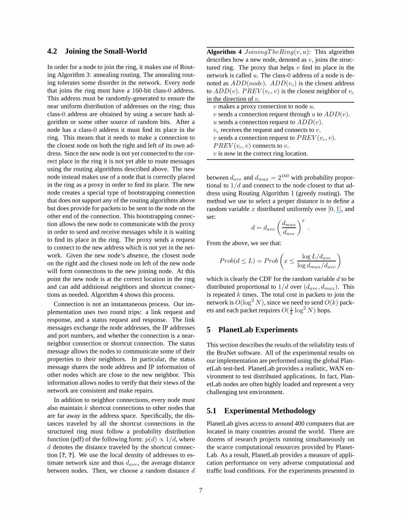
4.2 Joining the Small-World
In order for a node to join the ring, it makes use of Rout-ing Algorithm 3: annealing routing. The annealing rout-ing tolerates some disorder in the network. Every nodethat joins the ring must have a 160-bit class-0 address.This address must be randomly-generated to ensure thenear uniform distribution of addresses on the ring; thusclass-0 address are obtained by using a secure hash al-gorithm or some other source of random bits. After anode has a class-0 address it must find its place in thering. This means that it needs to make a connection tothe closest node on both the right and left of its own ad-dress. Since the new node is not yet connected to the cor-rect place in the ring it is not yet able to route messagesusing the routing algorithms described above. The newnode instead makes use of a node that is correctly placedin the ring as a proxy in order to find its place. The newnode creates a special type of bootstrapping connectionthat does not support any of the routing algorithms abovebut does provide for packets to be sent to the node on theother end of the connection. This bootstrapping connec-tion allows the new node to communicate with the proxyin order to send and receive messages while it is waitingto find its place in the ring. The proxy sends a requestto connect to the new address which is not yet in the net-work. Given the new node’s absence, the closest nodeon the right and the closest node on left of the new nodewill form connections to the new joining node. At thispoint the new node is at the correct location in the ringand can add additional neighbors and shortcut connec-tions as needed. Algorithm 4 shows this process.
Connection is not an instantaneous process. Our im-plementation uses two round trips: a link request andresponse, and a status request and response. The linkmessages exchange the node addresses, the IP addressesand port numbers, and whether the connection is a near-neighbor connection or shortcut connection. The statusmessage allows the nodes to communicate some of theirproperties to their neighbors. In particular, the statusmessage shares the node address and IP information ofother nodes which are close to the new neighbor. Thisinformation allows nodes to verify that their views of thenetwork are consistent and make repairs.
In addition to neighbor connections, every node mustalso maintaink shortcut connections to other nodes thatare far away in the address space. Specifically, the dis-tances traveled by all the shortcut connections in thestructured ring must follow a probability distributionfunction (pdf) of the following form:p(d) ∝ 1/d, whered denotes the distance traveled by the shortcut connec-tion [?, ?]. We use the local density of addresses to es-timate network size and thusdave, the average distancebetween nodes. Then, we choose a random distanced
Algorithm 4 JoiningTheRing(v, u): This algorithmdescribes how a new node, denoted asv, joins the struc-tured ring. The proxy that helpsv find its place in thenetwork is calledu. The class-0 address of a node is de-noted asADD(node). ADD(vc) is the closest addressto ADD(v). PREV (vc, v) is the closest neighbor ofvc
in the direction ofv.v makes a proxy connection to nodeu.v sends a connection request throughu to ADD(v).u sends a connection request toADD(v).vc receives the request and connects tov.v sends a connection request toPREV (vc, v).PREV (vc, v) connects tov.v is now in the correct ring location.
betweendave anddmax = 2160 with probability propor-tional to1/d and connect to the node closest to that ad-dress using Routing Algorithm 1 (greedy routing). Themethod we use to select a proper distance is to define arandom variablex distributed uniformly over[0, 1], andset:
d = dave
(
dmax
dave
)x
.
From the above, we see that:
Prob(d ≤ L) = Prob
(
x ≤log L/dave
log dmax/dave
)
which is clearly the CDF for the random variabled to bedistributed proportional to1/d over (dave, dmax). Thisis repeatedk times. The total cost in packets to join thenetwork isO(log2 N), since we need to sendO(k) pack-ets and each packet requiresO( 1
klog2 N) hops.
5 PlanetLab Experiments
This section describes the results of the reliability testsofthe BruNet software. All of the experimental results onour implementation are performed using the global Plan-etLab test-bed. PlanetLab provides a realistic, WAN en-vironment to test distributed applications. In fact, Plan-etLab nodes are often highly loaded and represent a verychallenging test environment.
5.1 Experimental Methodology
PlanetLab gives access to around 400 computers that arelocated in many countries around the world. There aredozens of research projects running simultaneously onthe scarce computational resources provided by Planet-Lab. As a result, PlanetLab provides a measure of appli-cation performance on very adverse computational andtraffic load conditions. For the experiments presented in
7

1
0.5
01.0 x 1046 3.4 x 1047 6.7 x 1047
CD
F(d
)
d
CDF(d)log(d) fit
Figure 2: The 1-D Kleinberg small-world structure re-quires that the distances of the shortcut connections havea pdfp(d) ∝ 1/d. In this PlanetLab experiment, we seethat the cdf(d) follows the expected logarithmic distribu-tion for a network of size 1060.
this section, around 100 PlanetLab machines were em-ployed.
The current implementation is in C# using the Monodevelopment platform. In order to minimize memory andother computational resource usage on PlanetLab ma-chines, we run multiple nodes inside a single Mono run-time process. As a result, many nodes can reside on asingle machine. However, each node is executed on aseparate thread and maintains its own connections anddata. Furthermore since class-0 addresses are assignedrandomly, nodes that reside on the same physical ma-chine are unlikely to be close to each other on the ad-dress space. We note that the UDP transport is used forall experiments presented in this section2.
In our experiments, we wish to see that the structure ofthe network is correct, that the system can indeed routepackets, and that the system is robust to node arrivals andfailures. We analyze the logs of our experiments with asoftware tool which shares no code with the BruNet sys-tem itself. The metric we use to measure the robustnessof the network is routability. Routability of the networkdefined as the fraction of pairs of nodes which can com-municate using the standard (in this case greedy) routingalgorithm.
5.2 Structure Verification
As discussed in Sections 3.1 and 4, all nodes are identi-fied by a unique 160-bit addresses, which can be inter-preted as integers; nodes are arranged in a ring, with theconvention that the integer representation of the node ad-dresses increase in the clockwise direction. Furthermore,
2We have verified that the system on a TCP transport delivers com-parable performance to UDP.
our structured small-world routing network requires thateach node keeps two neighbor connections to two closestclass-0 address in the clockwise direction and counter-clockwise direction. In other words, the structured ringis correct if and only if the following is true: every nodehas connections to its first and second class-0 neighborson the clockwise and the counterclockwise directions inthe address space.
We have successfully deployed a correct structuredring of size 1060 nodes on PlanetLab. It is difficult tosee much in visualizations of such large graphs, howeverwe present several figures for various sized networks inFigure 1 and Figures 9-11.
We verified the correctness of the shortcut distancedistribution by conducting the following: After the de-ployment of a correct 1060-node structured ring, all theshortcut connection distances are extracted from the ex-periment logs. The cumulative distribution function (cdf)of the shortcut distances are plotted in Figure 2. Note thatthe experimental cdf curve is in good agreement with theexpected curve:cdf(d) ∝ log(d).
5.3 Churn
Nodes do not stay in a P2P network indefinitely. One ofthe most striking aspects of the P2P network paradigm isthat we assume that nodes are fundamentally faulty andwill join and leave a network unexpectedly. Any real sys-tem must deal with unexpected arrivals and departures,which is called churn.
A major question is: will a node complete the joiningprocess correctly, in the presence of a slightly disorderednetwork, before the node departs. There are two impor-tant time scales in the churn process: the mean round-trip-time (RTT) between the hosts at the IP layer, and themean session time of the node. As the session time ap-proaches the RTT, clearly the system will not work prop-erly. Since each node requires two neighbor connectionsand at least one shortcut connection, the time required toestablish the node will be much greater than the RTT.
In our experiment, we created a correct network of 980nodes on PlanetLab. Once the network was correct, wethen started the system churning for 25 minutes. Eachsecond, with a fixed probability, every node abruptlygoes offline, and then rejoins the network. This corre-sponds to an exponential distribution on session time.
Figure 3 shows the results of our experiment. Wefind that when mean session time is above 12 minutes,the system is more than99% routable, however as meansession time decreases to 5.7 minutes, we find that thesystem becomes significantly more disordered with aroutability of 84%. Further decreasing the mean sessiontime causes the system to fall apart and tend to very lowvalues of routability. Exactly how the system transistions
8
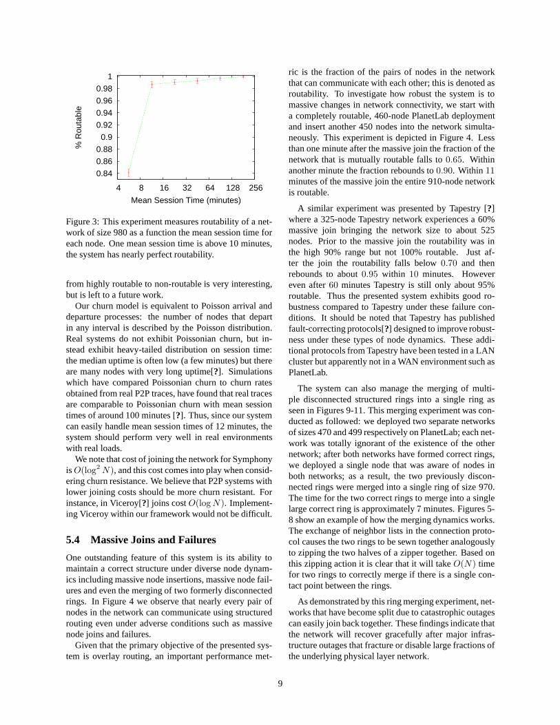
0.84
0.86
0.88
0.9
0.92
0.94
0.96
0.98
1
4 8 16 32 64 128 256
% R
outa
ble
Mean Session Time (minutes)
Figure 3: This experiment measures routability of a net-work of size 980 as a function the mean session time foreach node. One mean session time is above 10 minutes,the system has nearly perfect routability.
from highly routable to non-routable is very interesting,but is left to a future work.
Our churn model is equivalent to Poisson arrival anddeparture processes: the number of nodes that departin any interval is described by the Poisson distribution.Real systems do not exhibit Poissonian churn, but in-stead exhibit heavy-tailed distribution on session time:the median uptime is often low (a few minutes) but thereare many nodes with very long uptime[?]. Simulationswhich have compared Poissonian churn to churn ratesobtained from real P2P traces, have found that real tracesare comparable to Poissonian churn with mean sessiontimes of around 100 minutes [?]. Thus, since our systemcan easily handle mean session times of 12 minutes, thesystem should perform very well in real environmentswith real loads.
We note that cost of joining the network for SymphonyisO(log2 N), and this cost comes into play when consid-ering churn resistance. We believe that P2P systems withlower joining costs should be more churn resistant. Forinstance, in Viceroy[?] joins costO(log N). Implement-ing Viceroy within our framework would not be difficult.
5.4 Massive Joins and Failures
One outstanding feature of this system is its ability tomaintain a correct structure under diverse node dynam-ics including massive node insertions, massive node fail-ures and even the merging of two formerly disconnectedrings. In Figure 4 we observe that nearly every pair ofnodes in the network can communicate using structuredrouting even under adverse conditions such as massivenode joins and failures.
Given that the primary objective of the presented sys-tem is overlay routing, an important performance met-
ric is the fraction of the pairs of nodes in the networkthat can communicate with each other; this is denoted asroutability. To investigate how robust the system is tomassive changes in network connectivity, we start witha completely routable, 460-node PlanetLab deploymentand insert another 450 nodes into the network simulta-neously. This experiment is depicted in Figure 4. Lessthan one minute after the massive join the fraction of thenetwork that is mutually routable falls to0.65. Withinanother minute the fraction rebounds to0.90. Within 11minutes of the massive join the entire 910-node networkis routable.
A similar experiment was presented by Tapestry [?]where a 325-node Tapestry network experiences a 60%massive join bringing the network size to about 525nodes. Prior to the massive join the routability was inthe high 90% range but not 100% routable. Just af-ter the join the routability falls below0.70 and thenrebounds to about0.95 within 10 minutes. Howevereven after60 minutes Tapestry is still only about 95%routable. Thus the presented system exhibits good ro-bustness compared to Tapestry under these failure con-ditions. It should be noted that Tapestry has publishedfault-correcting protocols[?] designed to improve robust-ness under these types of node dynamics. These addi-tional protocols from Tapestry have been tested in a LANcluster but apparently not in a WAN environment such asPlanetLab.
The system can also manage the merging of multi-ple disconnected structured rings into a single ring asseen in Figures 9-11. This merging experiment was con-ducted as followed: we deployed two separate networksof sizes 470 and 499 respectively on PlanetLab; each net-work was totally ignorant of the existence of the othernetwork; after both networks have formed correct rings,we deployed a single node that was aware of nodes inboth networks; as a result, the two previously discon-nected rings were merged into a single ring of size 970.The time for the two correct rings to merge into a singlelarge correct ring is approximately7 minutes. Figures 5-8 show an example of how the merging dynamics works.The exchange of neighbor lists in the connection proto-col causes the two rings to be sewn together analogouslyto zipping the two halves of a zipper together. Based onthis zipping action it is clear that it will takeO(N) timefor two rings to correctly merge if there is a single con-tact point between the rings.
As demonstrated by this ring merging experiment, net-works that have become split due to catastrophic outagescan easily join back together. These findings indicate thatthe network will recover gracefully after major infras-tructure outages that fracture or disable large fractions ofthe underlying physical layer network.
9

1e-04 0.001
0.01 0.1
1
0 20 40 60 80 100 120
Time (minutes)
% Missing Edges
0 0.2 0.4 0.6 0.8
1
% Correct Routes
0
250
500
750
1000
N
450-NodeMassive Join
450-NodeMassive Failure
Figure 4: The network is very robust during gradual joins, massive joins and massive failures of nodes. After abruptchanges in connectivity, the network structure heals back to a perfect ring very rapidly and achieves overwhelmingpercentage routability long before the ring is completely correct. This demonstrates the applicability of the system tohighly dynamic applications. Moreover, from examining thebottommost figure, one can observe that the number ofmissing edges in the network decreases exponentially fast in time after the massive join of 450 nodes.
A
B
C
D
Ring 1
Ring 2
E
Figure 5: Two distinctroutable rings denoted asRing 1 and Ring 2 canbe merged into a largeroutable ring. Here we de-pict Ring 1 merging withRing 2.
A
B DE
C
Figure 6: ”C” connects to”B” and ”D”, the two clos-est nodes on ring2. As anormal part of the connec-tion protocol, ”C” sends itneighbor lists to ”B” and”D”.
A
B DE
C
Figure 7: Based on theneighbor-list informationobtained from ”C” whileconnecting, ”B” connectsto ”A” and ”D” connectsto ”E”.
A
B DE
C
Figure 8: The network isnow correctly ordered butthere are many more con-nections than are needed.Each node maintainskconnections to the closestneighbors on the right andleft (k = 1 in this exam-ple). Each node will trimthe excess connections un-til only the k closest oneach side remain.
10
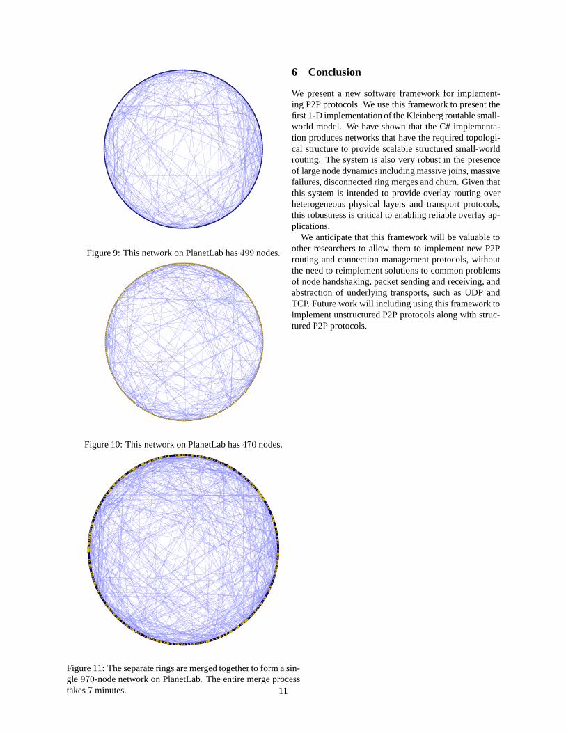
Figure 9: This network on PlanetLab has499 nodes.
Figure 10: This network on PlanetLab has470 nodes.
Figure 11: The separate rings are merged together to form a sin-gle 970-node network on PlanetLab. The entire merge processtakes7 minutes.
6 Conclusion
We present a new software framework for implement-ing P2P protocols. We use this framework to present thefirst 1-D implementation of the Kleinberg routable small-world model. We have shown that the C# implementa-tion produces networks that have the required topologi-cal structure to provide scalable structured small-worldrouting. The system is also very robust in the presenceof large node dynamics including massive joins, massivefailures, disconnected ring merges and churn. Given thatthis system is intended to provide overlay routing overheterogeneous physical layers and transport protocols,this robustness is critical to enabling reliable overlay ap-plications.
We anticipate that this framework will be valuable toother researchers to allow them to implement new P2Prouting and connection management protocols, withoutthe need to reimplement solutions to common problemsof node handshaking, packet sending and receiving, andabstraction of underlying transports, such as UDP andTCP. Future work will including using this framework toimplement unstructured P2P protocols along with struc-tured P2P protocols.
11

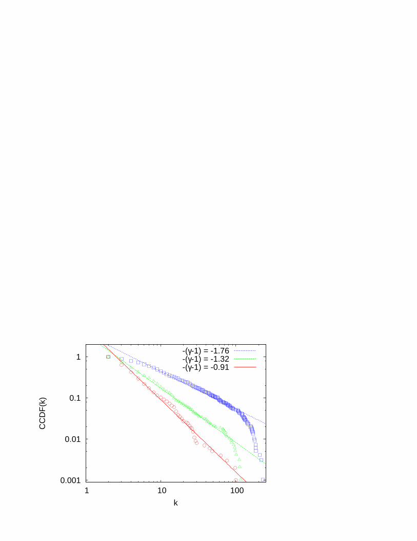
0.001
0.01
0.1
1
1 10 100
CC
DF
(k)
k
-(γ-1) = -1.76-(γ-1) = -1.32-(γ-1) = -0.91

N1
N5
N20
N7
N10
N8
N9
Structured Subgraph
Unstructured Subgraph
Related Documents