NASA SP-5115 FUEL CELLS A SURVEY By Bernard J. Crowe Prepared under Contract NASW-2173 by COMPUTER SCIENCES CORPORATION Falls Church, Virginia Technology Utilization O[fice 1973 NATIONAL AERONAUTICS AND SPACE ADMINISTRATION Washington, D.C. https://ntrs.nasa.gov/search.jsp?R=19730017318 2018-06-07T21:40:21+00:00Z

Welcome message from author
This document is posted to help you gain knowledge. Please leave a comment to let me know what you think about it! Share it to your friends and learn new things together.
Transcript

NASA SP-5115
FUEL CELLS
A SURVEY
By
Bernard J. Crowe
Prepared under Contract NASW-2173 byCOMPUTER SCIENCES CORPORATION
Falls Church, Virginia
Technology Utilization O[fice 1973
NATIONAL AERONAUTICS AND SPACE ADMINISTRATION
Washington, D.C.
https://ntrs.nasa.gov/search.jsp?R=19730017318 2018-06-07T21:40:21+00:00Z

NOTICE - This document is disseminated under the sponsorship of the NationalAeronautics and Space Administration in the interest of information exchange. The
United States Government assumes no liability for its contents or use thereof.
For sale by the Superintendent of DocumentsU.S. Government Printing Office, Washington, D.C. 20402
Price: 85 cents, domestic postpaid; 60 cents, GPO BookstoreStock No. 13300-00500
Library of Congress Catalog Card Number 72-600266
11
i

Foreword
Fuel cells, known in principle for over 100 years, are today being used or
considered for a variety of tasks. They have been applied as power forautomotive purposes, in a submarine, and to meet aerospace requirements.
They have actual or potential advantages such as freedom from toxic exhaust
emissions, relatively quiet operation, basic simplicity, and high efficiency.
This book is an attempt to discuss fuel cells factually, and to describe their
current status; many of the advances in technology have been carried out underNASA sponsorship. Problems as well as potentials are considered, and the
changes with the use of various fuels are looked at. Potential users should be
aware that there are no magic answers, yet fuel cells are a power source that
could be more widely used.
This is one of a series of publications dealing with specialized processes from
the standpoint of their applications'and methodology. It is part of a programestablished by the National Aeronautics and Space Administration to collect
the results of aerospace-related research and to evaluate, organize and
disseminate those results for the benefit of the industrial, educational, and
public communities of the Nation. The new technology so collected, and
prepared for appropriate audiences, is described and announced in suitable
documents, or by other means, and is so made available to potential users. This
is the function of the Technology Utilization program, which is characterized
by a user-oriented approach in its activities.
References to specific work, and to companies working on or with fuel cells,are provided for the reader who would like to delve into this area of
technology. It is hoped that the information will be of value to those interested
in developing or using fuel cells.
Director
Technology Utilization Office
III

Acknowledgments
Many individuals assisted in the preparation of this survey, supplying
material for inclusion or reviewing the draft. The author extends his thanks to:
David Bell, III, G. D. Hydrick, Fulton M. Plauche, and W. Eugene Rice, NASA
Manned Spacecraft Center; Leonard Berkowitz, Esso Research and Engineering
Company; Richard J. Boehme, Charles Graft, and John R. Morgan, NASA
Marshall Space Flight Center; Lloyd E. Chapman and Frank O'Brien, General
Electric Company; Ernst M. Cohn, NASA Headquarters; Warren Danzenbakerand Elliot Sivowitch, Smithsonian Institution; Robert W. Easter, Harvey J.
Schwartz, and Lawrence H. Th_ler, NASA Lewis Research Center; Charles L.
Fruchter, Computer Sciences Corporation; Dr. Jose Giner and Dr. Gerhard L.
Holleck, Tyco Laboratories, Inc.; Lawrence Handley and William E. Podolny,Pratt and Whitney Aircraft; Joseph H. Karshner, General Motors Corporation;Dr. Karl V. Kordesch and Dr. Robert Powers, Union Carbide Corporation;
Larry Rolufs, IRS; and Quentin J. O. Sullivan, Allis-Chalmers.Illustrations used in the survey were provided by courtesy of Allis-Chalmers
(figs. 5 and 6); American Institute of Chemical Engineers (fig. 31); Communi-cations Satellite Corporation (fig. 35); General Electric Company (Figs. 15,
25-29, 37-39); General Motors Corporation (figs. 53-56); Marine TechnologySociety Journal (figs. 30, 43); A. R. Poirier and AIAA (fig. 33); Pratt and
Whitney Aircraft (figs. 20, 23, 24, 36, 40, 41, 48, 49, 51, 52); Tyco
Laboratories, Inc. (figs. 46, 47); and Union Carbide Corporation (figs. 57-63).
IV

Contents
Page
Chapter 1. SUMMARY ................................. 1
Introduction ....................................... 1
About This Book .................................... 1
How Do Fuel Cells Work? .............................. 2
What Are the Advantages of Fuel Cells? ..................... 3
Why Aren't Fuel Cells in Widespread Use? ................... 4
Where Does the Fuel Cell Stand Today? ..................... 4
Chapter 2. DEVELOPMENT OF THE FUEL CELL .............. 7
Introduction ....................................... 7
The First Practical Fuel Cell ............................ 8
NASA Impetus to Fuel Cell Development ................... 11
Chapter 3. HOW THE FUEL CELL WORKS ................... 13
Understanding the Fuel Cell ............................ 13
Principle of Operation ................................ 13
Electrode Reactions .................................. 14
Power Generation ................................... 15
Loss Mechanisms .................................... 16
Chapter 4. THEORY INTO PRACTICE ....................... 19
The Design Process .................................. 19
A Practical Fuel Cell ................................. 19
The Apollo Fuel Cell System ............................ 27
The Gemini Fuel Cell System ............................ 35
Chapter 5. DOWN TO EARTH ............................ 41
Introduction ....................................... 41
Fuels Other Than Hydrogen ............................ 41
Hydrocarbon Fuels .................................. 44
Types of Hydrocarbon Fuel Cells ......................... 46
Direct Oxidation Cells ................................ 46
Indirect Oxidation, Internal Processing Cells .................. 47
Indirect Oxidation, External Processing Cells ................. 48
Regenerative Fuel Cells ................................ 50
Chapter 6 FUEL CELL TECHNOLOGY STATE-OF-THE-ART ....... 53
I ntroduction ....................................... 53V

VI FUEL CELLS
Page
Aerospace Fuel Cells ................................. 53
Nonaerospace Fuel Cells .............................. 56
Fuel Cell Costs .................................... 62
Chapter 7. APPLICATIONS OF FUEl CELLS ................. 65
Introduction ...................................... 65
A Fuel Cell Artificial Heart Power Supply .................. 67
Fuel Ceils for Domestic Power Supply ..................... 73
Automotive Power Applications ......................... 76
REffERENCES ...................................... 97
BIBLIOGRAPHY .................................... 101
Appendix A. SOURCES OF FURTHER INFORMATION ......... 105
Books .......................................... 105
Periodicals ....................................... 105
i
!iJ
J
i

CHAPTER 1
Summary
INTRODUCTION
When Sir William Grove demonstrated the first fuel cell in 1839, it musthave seemed to some observers that the event heralded the dawn of a new era
in the generation of electricity, accompanied as it was by Becquerel's almost
simultaneous discovery of the photovoltaic effect. Yet it was over 100 years
before Francis Thomas Bacon produced a fuel cell capable of generating useful
amounts of power, and another 25 years elapsed before the fuel cell was put topractical use.
Paradoxically, the fuel cell's first utility roles could hardly have been more
exotic; namely, providing electrical power for manned exploration of the
oceans and space. Indeed, it was the requirements of these exotic missions that
made the fuel cell a competitive power-generation candidate for the first time
in the face of opposition from hitherto superior techniques. In applications •such as these, the fuel cell's unusual characteristics made it a cost-effective
solution to problems peculiar to the hostile environments encountered.
To satisfy the requirements of such applications, the fuel cell concept was
subjected to an intensive research and development effort during the lastdecade. This largely NASA-sponsored effort has taken the fuel cell from the
status of a demonstration device to that of a sophisticated source of electrical
power. Investigators and technologists seek to apply current developments inthis field to a number of other, though admittedly less exotic, terrestrial
applications. Among the potential advantages claimed for the device are highefficiency, quiet and trouble-free operation, and freedom from toxic andpollutant exhaust emissions.
Why then is the fuel cell not in common use? Surely such an uncommon
energy-conversion system has innumerable applications? Answers to thesequestions form the topics of this book.
ABOUT THIS BOOK
This book is a survey of fuel cell technology and applications; it does not
deal with conventional galvanic cells or "storage batteries," nor with hybrids
such as the zinc-air battery, which is half fuel cell, half battery. It is not a text
book on fuel cells, although references to sources of information are providedfor those who wish to know more about the theory, electrochemistry, anddesign of these useful devices.
2 FUELCELLS
The primary goal is to acquaint the reader with the fuel cell, its operating
principles, its performance capabilities and its limitations. Most importantly, a
number of applications are considered to show how and why different types of
fuel cells are best suited to certain roles. The purpose of the survey is to make
available accumulated experiences in fuel cell technology, many of which have
resulted from research and development programs supported by NASA, and to
show how this technology might be put to use in down-to-earth applications.
HOW DO FUEL CELLS WORK?
Like the familiar dry cell and lead-acid batteries, fuel cells work by virtue of
electrochemical reactions in which the molecular energy of a fuel and an
oxidant are transformed into direct current electrical energy.
Unlike batteries, however, fuel ceils do not consume chemicals that form
part of their structure or are stored within the structure; the reactants are
supplied from outside the cell. Since the fuel cell itself does not undergo an
irreversible chemical change, it can continue to operate as long as its fuel and
oxidant are supplied andproducts removed, or at least until the electrodes cease
to operate because of mechanical or chemical deterioration. In comparison
with a conventional battery, this period of operation may be a significantly
longer time.
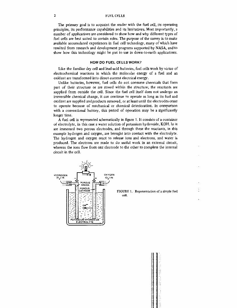
A fuel cell is represented schematically in figure 1. It consists of a containerof electrolyte, in this case a water solution of potassium hydroxide, KOH. In it
are immersed two porous electrodes, and through these the reactants, in this
example hydrogen and oxygen, are brought into contact with the electrolyte.
The hydrogen and oxygen react to release ions and electrons, and water is
produced. The electrons are made to do useful work in an external circuit,whereas the ions flow from one electrode to the other to complete the internal
circuit in the cell.
HYDROGEN
(H 2) IN
. o-°
o _
° o
PO'I
POROUS" ANODE
POROUS
CATHODE --
.- _-.-.-:- _-- - I- -- OH-- -!
_ _--,_-__
"-"-_ e I OXYGEN
tO 21 i N
:., - __-.,
L!-:l_
:(.j- 7.._.: _-_-
;IUM HYbR( _ 3E -
ELECTROLYTE
FIGURE l.-Representation of a simple fuelcell.

SUMMARY 3
If the hydrogen and oxygen were simply mixed as gases at room
temperature, then, of course, no reaction would take place. Raising the
temperature of the mixture would cause an explosion, liberating some of the
energy in the mixture in a very short period of time and releasing it mainly asheat. The fuel cell is a device in which conditions are created to enable the
controlled release of this energy. Exactly how this is accomplished is described
in Chapter 3.
WHAT ARE THE ADVANTAGES OF FUEL CELLS?
As we have seen, fuel cells convert chemical energy into electrical energy. Of
course they are not unique in this respect; a diesel-generator set, for example,
does the same thing. The importance of the fuel cell is in the way in which iteffects this conversion.
This is represented schematically in figure 2. The diesel-generator converts
chemical energy into heat, heat into mechanical motion, and mechanical
motion into electricity. The fuel cell performs a one-step, direct transformation
of chemical energy into electricity, and although heat is given off in the process
it does not constitute an essential link in the energy-conversion chain. Because
DIESEL-GENERATOR FUELCELL
I cHEMICAL !
L,_ENERG_
ll:
ELECTRICITY I
FIGURE 2.-Comparison ofgenerator and a fuel cell.
]FELECTRICITY , ]
energy transformation processes in a diesel

4 FUEL CELLS
it bypasses these intermediate steps, the fuel cell does not suffer the energylosses characteristic of thermomechanical devices such as the diesel engine.
Consequently, more available fuel energy may be converted into useful
electrical energy and as a result, the fuel cell may be more efficient. Because
the reaction takes place chemically, the elementary fuel cell has no moving
parts to cause vibration and noise. In practice, pumps and other smallmechanical units are often required as auxiliaries to the cell, but in general fuel
cells run more smoothly and quietly than other power-generation devices.
Perhaps the most important advantage of the fuel cell is that its combustion
products are often lower in volume and less hazardous than those from theinternal combustion engine. Potentially, the fuel cell is a dean, nonpolluting
source of electrical energy. In today's world of ecological awareness and
environmental concern, this is an important attribute.
WHY AREN'T FUEL CELLS IN WIDESPREAD USE?
With all these advantages, why aren't fuel cells being used in widespread
practical applications?The answer lies largely in the relative immaturity of the fuel cell as a
practical power-conversion device. To be sure, fuel cells have provided ourastronauts with life-sustaining electrical power from here to the Moon and back
again. But it is only in the last 10 years that such things have become possibleand the fuel cell has been significantly understood. The automobile engine, the
electric generator, and the battery have all been around for a much longer
period. They are in an advanced stage of development and are produced inlarge quantities. The fuel cell, on the other hand, is still very much in a
developmental stage and has never been produced in quantities of more than a
few dozen at a time. In comparison with these older devices the fuel cell is
prohibitively expensive for many applications.
Cost is not the only block. The fuel cells that powered the Gemini and
Apollo spacecraft used pure hydrogen and oxygen as their sources of energy.
To be of use on earth, many feel that fuel cells must be capable of using fuels
that are more readily available, easier to handle, less expensive, and lesshazardous. However, there is disagreement about which fuels meet these
requirements and which are best for each application. Converting the classic
hydrogen-oxygen cell to use any other fuel raises many problems. Lifetime,
maintainability, and reliable unattended operation are other problems thatmust be solved before the fuel cell can take its place beside more familiar
devices in day-to-day operation. In chapter 5 we will look at these problems indetail and examine some of the variants of the basic hydrogen-oxygen fuel cell.
WHERE DOES THE FUEL CELL STAND TODAY?
Despite the myriad technical problems confronting the engineer in his
i;i ii

SUMMARY 5
attempts to adapt the fuel cell to prosaic tasks, some progress has been made.In remote locations, fuel cells are powering radio relay stations and beacons.
In military situations, fuel cells that can run on an extraordinary range of
common fuels provide power for communications and other apparatus. Around
the United States fuel cells are on shakedown trials in homes, apartments,
shops, and factories producing electricity directly from natural gas. InCleveland an automobile powered by a fuel cell/battery combination carries its
designer to and from work each day. And in the laboratory, a fuel cell is being
developed that might some day be implanted in the body of a man or womanto power an artificial heart.
The enthusiasm of the 1960's which saw the fuel cell as a panacea to many
social ills has given way in the seventies to cautious optimism-an optimism
which sees potential uses for fuel cells on many fronts, but which recognizes
the many problems to be solved before that potential can be realized. This,
then, appears to be an appropriate time to review fuel cell technology.

!iit

PRECEDING PAGE BLANK NOT FILMED
CHAPTER 2
Development of the Fuel Cell
INTRODUCTION
It is natural to think of the fuel cell as a product of twentieth century
technology, since it has achieved prominence only in the last 10 years.
However, the fuel cell concept dates back to the mid-1800's when, it is
generally agreed, the first recorded demonstration of the principle was made by
Sir William Grove (ref. 1), an English scientist working in the youthful field of
electricity. Grove was famous in his lifetime as the inventor of a relativelyconventional galvanic cell or "battery" that became known as the Grove Cell
(ref. 2). His work on fuel cells was not recognized until much later.
An excursion into the field of electrolysis apparently led Grove to his
discovery of the fuel cell principle. He reasoned that if electricity decomposed
water into hydrogen and oxygen, then it might be possible to arrange the
synthesis of water from its components so as to generate electricity. In hisclassic experiment reported in 1839 (ref. 1), Grove constructed the first known
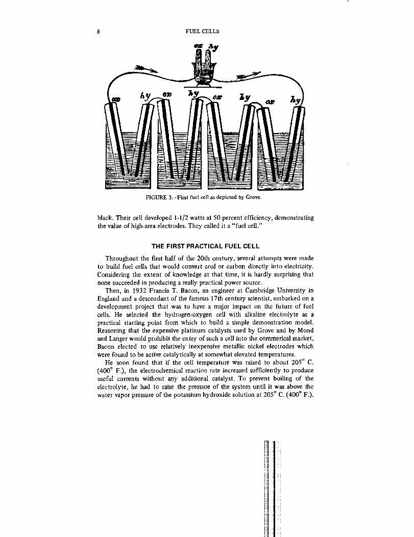
fuel cell, noting that it produced only a small current. In 1842, he built a bank
of 50 such cells and called it a "gaseous voltaic battery" (ref. 3). Eachelectrode of 1]4-inch platinized platina foil was covered by a glass tube and
immersed in dilute sulfuric acid. Alternate tubes contained hydrogen andoxygen (fig. 3).
In a graphic description of the effects produced by his battery, Grove
noted: "A shock was given which could be felt by five persons joining hands,
and which when taken by a single person was painful." His insight into the
mechanisms of the cell was remarkable; Grove clearly recognized thedesirability of high-surface area electrodes, but elected not to construct them
because of the difficulties involved. Although his battery worked, it was not
capable of delivering significant power when compared with more conventional
galvanic cells, and he shortly abandoned this line of research. Perhaps the fuel
cell's potential for continuous operation did not occur to Grove. In any event,
such an attribute probably would not have appeared significant, for mostgalvanic cells were beset with corrosion problems. Since the materials of the
cell could be expected to have only a short life, there was little point inproviding a continuous supply of reactants, especially when these were rare andexpensive gases.
As a result, 50 years elapsed before any significant advance was made on
Grove's "gaseous battery." In 1889 Mond and Langer (ref. 4) constructed a
similar device using perforated platinum electrodes catalized by platinum
FUEL CELLS
FIGURE 3.-First fuel cell as depicted by Grove.
black. Their cell developed 1-1/2 watts at 50 percent efficiency, demonstrating
the value of high-area electrodes. They called it a "fuel cell."
THE FIRST PRACTICAL FUEL CELL
Throughout the first half of the 20th century, several attempts were madeto build fuel cells that would convert coal or carbon directly into electricity.
Considering the extent of knowledge at that time, it is hardly surprising that
none succeeded in producing a really practical power source.Then, in 1932 Francis T. Bacon, an engineer at Cambridge University in
England and a descendant of the famous 17th century scientist, embarked on a
development project that was to have a major impact on the future of fuel
cells. He selected the hydrogen-oxygen cell with alkaline electrolyte as a
practical starting point from which to build a simple demonstration model.Reasoning that the expensive platinum catalysts used by Grove and by Mond
and Langer would prohibit the entry of such a cell into the commerical market,
Bacon elected to use relatively inexpensive metallic nickel electrodes whichwere found to be active catalytically at somewhat elevated temperatures.
He soon found that if the cell temperature was raised to about 205 ° C.
(400 ° F.), the electrochemical reaction rate increased sufficiently to produce
useful currents without any additional catalyst. To prevent boiling of the
electrolyte, he had to raise the pressure of the system until it was above the
water vapor pressure of the potassium hydroxide solution at 205 ° C. (400 ° F.).
,]1

DEVELOPMENT OF THE FUEL CELL 9
He then discovered that increasing the pressure resulted in a significant
performance increase, so he increased the pressure well above that required to
prevent boiling, operating the system at about 414 N/cm 2 (600 psi).
Bacon encountered many problems in developing electrodes with a
sufficiently large active area. One of the biggest problems was maintaining a
stable interface between the gas and the liquid. He solved this problem by using
porous electrodes made in two layers, one layer having a considerably greater
pore size than the other. With the gas on the coarse-pore side of the electrode
and the electrolyte on the fine-pore side, the interface position was controlled
by adjusting the pressure differential between gas and electrolyte.
Although his work was interrupted by World War II, Bacon's persistence
enabled him to construct what is generally agreed to be the first useful fuel cell(fig. 4). By the middle of the century he was able to demonstrate a 5-kilowatt
(kW) system capable of powering a welding machine, a circular saw, and a2-ton capacity fork lift truck.
Bacon's demonstration, and the work of others during this period, heralded
an explosive growth in fuel cell research in the early 1960's. After 120 years of
uncertain progress, the fuel cell began to emerge from the laboratory.
Developments occurred rapidly and numerous demonstrations were staged toillustrate the many applications of the device. Among those that received
considerable publicity were several developed by the Allis-Chalmers Manufac-
turing Company (fig. 5) between 1959 and 1963. The apparent sudden succes
of the fuel cell and the attendant publicity led to overestimation and
overselling of its capabilities as a cure for many domestic, economic, and
technical ills. Those working on a fuel cell development recognized only too
FIGURE 4.-Bacon's high-pressure fuel cell.

10 FUEL CELLS
FIGURE 5.-Early fuel cell-powered demonstration vehicles.
well the many problems to be solved in building and producing an economical
device.
However, not all the fuel cells built at that time were demonstration "toys."
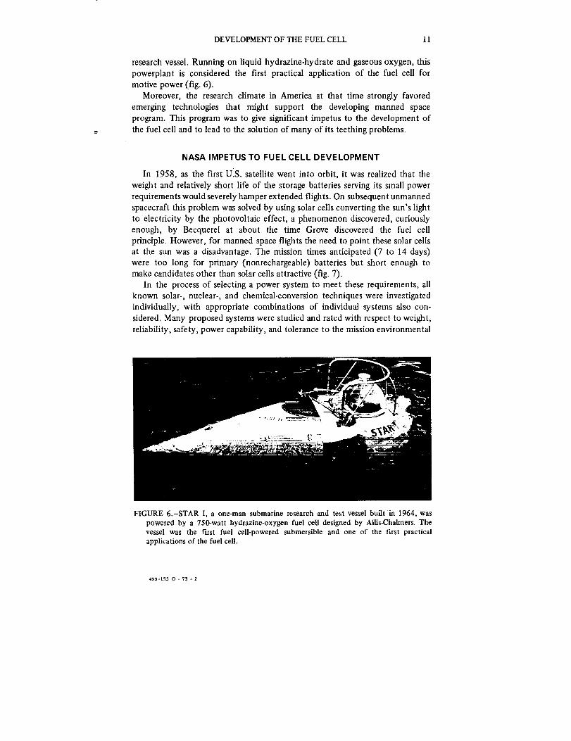
In 1964 Allis-Chalmers, under contract to General Dynamics' Electric Boat
Division, produced a 750-watt fuel cell system to power a one-man underwater
DEVELOPMENT OF THE FUEL CELL 11
research vessel. Running on liquid hydrazine-hydrate and gaseous oxygen, this
powerplant is considered the first practical application of file fuel cell for
motive power (fig. 6).
Moreover, the research climate in America at that time strongly favored
emerging technologies that might support the developing manned space
program. This program was to give significant impetus to the development of
the fuel cell and to lead to the solution of many of its teething problems.
NASA IMPETUS TO FUEL CELL DEVELOPMENT
In 1958, as the first UIS. satellite went into orbit, it was realized that the
weight and relatively short life of the storage batteries serving its small power
requirements would severely hamper extended flights. On subsequent unmanned
spacecraft this problem was solved by using solar cells converting the sun's lightto electricity by the photovoltaic effect, a phenomenon discovered, curiously
enough, by Becquerel at about the time Grove discovered the fuel cell
principle. However, for manned space flights the need to point these solar cells
at the sun was a disadvantage. The mission times anticipated (7 to 14 days)were too long for primary (nonrechargeable) batteries but short enough to
make candidates other than solar cells attractive (fig. 7).
In the process of selecting a power system to meet these requirements, allknown solar-, nuclear-, and chemical-conversion techniques were investigated
individually, with appropriate combinations of individual systems also con-
sidered. Many proposed systems were studied and rated with respect to weight,
reliability, safety, power capability, and tolerance to the mission environmental
FIGURE 6.-STAR I, a one-man submarine research and test vessel built in 1964, waspowered by a 750-watt hydrazine-oxygen fuel cell designed by AUis-Chalmers. Thevessel was the first fuel cell-powered submersible and one of the first practicalapplications of the fuel cell.
499-155 0 - 73 - 2

12 FUEL CELLS
104
I0 3
_0 2
5_0
i FIGURE 7.-Optimum operation for variousenergy-conversion devices, circa 1964.
O. 1
0.0lI 5 1 1 1 I I 10
m_n rain hf doy week m,nth year year
DURATION
profde. All candidates were required to have known improvement potential
that could be realized early in the development program.
It soon was discovered that the fuel cell system offered many advantages,
for example, absolute independence with respect to sunlight, aerodynamic
forces, and sea level pressure. The high operational efficiency of the fuel cell as
compared with conventional heat engines permitted the added advantage of
low specific fuel consumption and a lower heat rejection requirement. Because
potable water is a byproduct, of its electrochemical process, the hydrogen-
oxygen fuel cell could also supply water for crew consumption and humidifica-tion of cabin air. The fuel cell system was selected finally on the basis of these
advantages and others, such as its development status, low system effective
weight, and mission flexibility. The absence of solar arrays simplified launch
preparations and rendezvous requirements for spacecraft attitude control.As a result of this decision, NASA funded an extensive research and
development program aimed at solving or understanding some of the basic
problems and mechanisms of the fuel cell. More than 200 contracts were let to
industries and universities to study the basic physics, kinetics, electrochem-
istry, and catalysis of the fuel cell reaction; to develop methods of making
electrodes, retaining electrolytes, removing byproducts, and constructing
workable cells; and to investigate several promising approaches to the
construction of a practical power-generation system.
The fuel cell technology developed by Bacon in England was one of the
approaches investigated. Through the British National Research and Develop-ment Council and Leesona-Moos Laboratories, Pratt & Whitney Aircraft acquired
the patent to Bacon's fuel cell design in 1959. This technology was to form thebasis for the Apollo power plant and help take the first man to the Moon.
But before Apollo, the U.S. astronauts would develop their skills andtechnology on the Gemini series of earth-orbiting missions. Here too, the fuel
cell was to play a crucial role in supplying electrical power during space
missions longer than any undertaken at that time and not exceeded until well
into the manned lunar exploration phase of Apollo. However, the technology
of the cell itself was quite different from Bacon's, relying on a specialmembrane disclosed by W. T. Grubb in 1957 (ref. 5).
iIilIIFI

CHAFFER 3
How the Fuel Cell Works
UNDERSTANDING THE FUEL CELL
In considering the fuel cell for any application, it is necessary to appreciate
the limitations of the device and the differences between one type of cell andanother. A fundamental requirement for such an appreciation is an under-
standing of the fuel cell and its operation.Understanding the principle of operation of the fuel cell is not difficult. It
does not require an extensive knowledge of chemistry, thermodynamics, or
electricity, and the reader does not have to be versed in mathematics orcatalysis. Although knowledge of these and related subjects is a prime
requirement for electrochemists and technologists who design and develop fuel
cells, understanding the basic mechanisms involved, appreciating the losses
inherent in these mechanisms, and knowing how those losses may be reduced
or negated demand no specialized knowledge or skills.
PRINCIPLE OF OPERATION
The essential features of a single fuel cell are represented in figure 8. In this
example, hydrogen and oxygen are the fuel and oxidizer, respectively, and the
ANODEI'_¢_iO'T"ODEGASCHAMSERS_.. 1'3-_1"11I'H o,T,L 0
I,_ ELE_RODE,ELECTROL TE IFUEL (HYDROGEN) _ (' ,i['(OXYGENI OXIDIZER
FIGURE 8.-Basic operation of the fuel cell.
13

14 FUEL CELLS
electrolyte is a solution of potassium hydroxide. Other cells may use different
reactants and/or different electrolytes; however, the salient characteristics of
most cells are quite similar and our example serves to illustrate the general
principles of operation.
The cell consists essentially of a pair of electrodes separated by an
electrolyte. The reactants (in this case, gases) are fed through the porous
electrodes and brought into contact with the electrolyte. Reactions take place
that set up voltages, or electrical pressures, at the electrodes. When an external
load is connected to the electrodes, these voltages drive electrons through the
load and perform useful work. In the electrolyte solution, ions travel from one
electrode to the other to complete the electrical circuit.
To understand the cell's special features that make these reactions possible,
we must look more closely at the electrodes and at the processes that take
place there.
ELECTRODE REACTIONS
Hydrogen is fed to the anode and diffuses through the porous, conducting
electrode structure until it comes into contact with the electrolyte. The
potassium hydroxide electrolyte is rich in hydroxyl (OH-) ions. At the pointwhere it meets the electrolyte, hydrogen adsorbs upon the electrode surface in
an atomic form which renders it highly reactive. The hydrogen atoms react
with the hydroxyl ions to form water; and as a result of this reaction, free
electrons are left on the anode. The reaction may be represented by the
equation:
Anode + H2 + 2OH---, (Anode + 2e-) + 2H20
Electrons accumulate at the electrode/electrolyte interface where they
attract a corresponding quantity of positive ions (in this case, potassium ions,
K +) in the electrolyte solution. A potential energy barrier prevents the positive
ions from reaching the electrode surface, so that an opposing layer of electrons
and positive ions is set up close to the surface (fig. 9). These layers ofcharge act in a similar manner to those on the plates of a capacitor, and the
potential gradient thus created is part of the essential "driving force" of thefuel cell.
At the cathode, oxygen reacts with the water in the electrolyte to form
hydroxyl ions. During this reaction, electrons are removed from the cathode,
resulting in a positive charge. The potential difference between the cathode and
the adjacent electrolyte supplements the overall Cell potential, as shown infigure 10. The reaction at the cathode may be expressed as:
(Cathode + 2e-) +_'O2 + H20 Cathode + 2OH-
In the absence of an electrical connection between the anode and cathode,
these reactions quickly achieve equilibrium. The ideal cell voltage ("open
ii
1I

HOW THE FUEL CELL WORKS 15
/*-/
/" /LAYER OFELECTRON5 e- j
(/
/'-/
/_LECTR®E
LAYER OFPOSITIVE ION5
e_
--I
--__?__
__.? --FIGURE 9.-The
potential.origin of the electrode
v : v_-v I
.".....'..'::'.'" E2 i'-.'.
.-. "-''.." " • .'.''" I''." _=
FIGURE lO.-Cell potential as sum of half-cell voltages,
E = E2-E 1
Icircuit" voltage) is equal to the potential E, and no further fuel or oxidizer isconsumed.
The cell maintains this voltage because the electrons cannot travel through
the electrolyte, since it is not a good conductor. However, if a lamp or an
electric motor is connected across the terminals of the cell, electrons will flow
through it from anode to cathode under the influence of the fuel cell's voltage
or potential. This flow of electrons, or current, can be made to do useful work
(i.e., light a lamp or turn a motor).
As electrons are removed from the anode, hydroxyl ions combine with

16 FUEL CELLS
hydrogen ions to form water. As the adsorbed hydrogen is consumed in this
way, fresh gas from the supply diffuses through the electrode to take its place.
At the cathode, returning electrons facilitate the production of hydroxyl
ions from the oxygen and from water in the electrolyte. The hydroxyl ions,
which are free to move in the electrolyte, flow from cathode and anode,
completing the electrical circuit. Although all the hydroxyl ions are consumed
in the reaction, only half of the water formed at the anode is consumed in the
cathodic reaction. The remaining water constitutes a byproduct of the reaction
and must be removed to avoid diluting the electrolyte. These reactions are
shown in figure 11.
The foregoing description is a simplification of the processes that take place
within a practical fuel cell. Moreover, the reactions differ in detail between one
type of cell and another since they depend upon the fuel-oxidizer-electrolyte
combination in use, and to a lesser extent on the temperature and pressure at
which the cell operates. Nevertheless, the description of the essential
mechanisms of voltage origin and ionic transport in the hydrogen-oxygen-
alkaline fuel cell serves to illustrate the general principles of operation, and this
description will aid in examining the fuel cell as a power-generating device.
POWER GENERATION
The discussion of electrode reactions stated that the open circuit voltage of
the fuel cell is equal to the sum of the electrode potentials, E. The potential
difference or voltage generated within the cell when no current is being drawn
(and therefore no useful work is being done) is determined by the free energy
of reaction of the chemical constituents of the cell. For hydrogen and oxygen
this is 1.23 volts at 10.13 N/cm 2 (1 atmosphere) and 25 ° C. (77 ° F.). The
value of E varies from a few millivolts (nitrous oxide and chlorine) to almost 3
volts (hydrogen and fluorine) depending upon the electrochemical couple, but
2e
t _ -- ELECTRICAL LOAD
..o_L!7'e _f |"_O---_H20 !'"_O__O,_-
H*.O---I--,OVERALL REACTIOf¢
H 2 ¢ Y.O 2 • HT/O
ALKALINE
A_ODE I EL_CTROLY'FE CATHOOE
i
• _0 2
FIGURE ll.-Schematic representation ofreactions taking place in a hydrogen-
oxygen fuel cell with an alkaline elec-trolyte.
i'-
!=i

HOWTHE FUEL CELL WORKS 17
i FIGURE 12.-Voltage, current and powerrelationships in a typical fuel cell.
eon_wr
Austin (ref. 6) has shown that for several preferred couples the open circuitpotential lies in the range of 1.12 to 1.56 volts.
When current is drawn from the cell, however, the working voltage falls to a
lower value as shown in figure 12. Because the power output of the cell is the
product of the instantaneous voltage and current, it rises from zero (at zerocurrent) to some maximum and then declines as increasing current drain causesgreater and greater loss in voltage.
The loss in voltage that occurs when current is drawn from the cell is termed
"polarization," and results from three major loss mechanisms. These losses are
of paramount concern to the fuel cell designer since they result in decreased
efficiency and power. Maximization of efficiency and power as a function of
weight, volume, or cost is almost invariably a design goal.
To appreciate the design and construction features of fuel cells, it is
advantageous to understand these loss mechanisms and the ways of reducingtheir effects.
LOSS MECHANISMS
The three basic loss mechanisms encountered in fuel cell operation areohmic, concentration, and activation polarization. Ohmic polarization occursas a result of electrical resistance losses in the cell. These resistances occur in
the electrolyte, in the electrodes and, to a lesser extent, in the terminal
connections of the cell. Because the fuel cell is an inherently low voltagedevice, significant currents must be drawn to generate useful amounts of
power. Since ohmic OR) losses are directly related to current, even quite small
resistances can give rise to significant losses. For example, in a cell producing
200 amperes at approximately 0.55 volt, an internal resistance of only 1/1000
of an ohm causes an ohmic polarization loss of 0.2 volt. This represents a loss of
approximately 36 percent in power output at peak power. To reduce such
losses, electrodes are designed to have high conductivity and are closely spacedto minimize electrolyte resistance.
The second type of loss, concentration polarization, is caused by electrolytedepletion in the region of the electrode-electrolyte interface. Since the
reactions producing the flow of current cannot take place in the absence of

18 FUELCELLS
reactants and their intermediate products (e.g., hydroxyl ions), any reduction
in availability of these supplies leads to a corresponding loss in output of thecell. Cells are therefore constructed so that reactants may be fed to as large an
area of the electrode as possible, and electrodes are made highly porous to
minimize mass transport losses. Electrolytes are used at high concentrations to
ensure an adequate supply of ions at the electrodes.
The last type of loss, activation polarization, results when the interaction ofan oxidant or fuel with its electrode is too slow. When this happens, a portion
of the electrode potential is lost in driving the reaction to the rate required by
the current demand. The reaction rate is dependent upon the activity or energystate of the molecules participating in the reaction, and it increases with
temperature. Therefore, activation polarization may be reduced by raising the
operating temperature of the cell or by increasing the activity through the use
of a catalyst.

CHAPTER 4
Theory into Practice
After reviewing the fuel cell's operational principles and the mechanisms
that limit performance, it is appropriate to consider the construction of a
practical hydrogen-oxygen fuel cell and its integration into a system or
powerplant. The last chapter concluded with some general guidelines for
reducing the polarization, or voltage loss, in a fuel cell operating under load.
These guidelines will be examined to show how they effectively dictate the
geometry or layout of single cells and thus, to an extent, the design of fuel cell
systems.
THE DESIGN PROCESS
In most engineering endeavors it is unusual to find an unmitigated solution
to a given problem. Most frequently the solution to one problem gives rise toanother, so that the procedure becomes one of compromise, selecting a
solution that approaches the design goal as closely as possible without creating
more problems than it solves. So it is with the fuel cell. Moreover, each type of
fuel cell possesses its own set of problems and solutions, making it difficult to
formulate a completely general description of the design process. Therefore,
for the purposes of illustration we shall look first in a general way at fuel cell
design, and then at some specific examples to see how this design procedure
has been implemented.
A PRACTICAL FUEL CELL
The representation of a fuel cell in figure 1 embodies the essential elementsof a single cell, but if such a cell were constructed it would perform poorly fora number of reasons. The reactants would have to travel considerable distances
through the porous electrodes to reach the extremities, and under high current
demand the lower ends of the electrodes would probably be "starved" of gas.
The hydroxyl ions flowing from anode to cathode would have to traverse a
wide gulf of electrolyte and the cell would suffer ohmic losses as a result.
Another obstacle encountered with such a cell would be that of building a
"stack" or battery of cells to attain an acceptable system voltage; the result
would be far from compact, to say the least.
Many of these problems had been addressed and solved, at least partially, in
Bacon's cell and devices built by others at that time. The solution was to
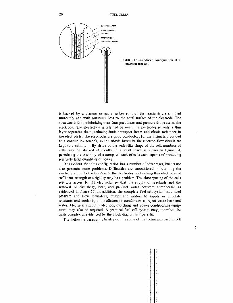
construct cells in a thin sandwich or wafer configuration as shown in figure 13.
Consider for a moment the behavior of a single cell of this kind. Each electrode
19
20 FUEL CELLS
OXYGENCHAMB[R
/°' ............
HYDnOGEN CHAMBER
FIGURE 13.-Sandwich configuration of apractical fuel cell.
is backed by a plenum or gas chamber so that the reactants are supplied
uniformly and with minimum loss to the total surface of the electrode. The
structure is thin, minimizing mass transport losses and pressure drops across the
electrode. The electrolyte is retained between the electrodes so only a thin
layer separates them, reducing ionic transport losses and ohmic resistance in
the electrolyte. The electrodes are good conductors (or are intimately bonded
to a conducting screen), so the ohmic losses in the electron flow circuit are
kept to a minimum. By virtue of the wafer-like shape of the cell, numbers of
cells may be stacked efficiently in a small space as shown in figure 14,
permitting the assembly of a compact stack of cells each capable of producing
relatively large quantities of power.
It is evident that this configuration has a number of advantages, but its use
also presents some problems. Difficulties are encountered in retaining the
electrolyte due to the thinness of the electrodes, and making thin electrodes of
sufficient strength and rigidity may be a problem. The close spacing of the cells
restricts access to the electrodes so that the supply of reactants and the
removal of electricity, heat, and product water becomes complicated as
evidenced in figure 15. In addition, the complete fuel cell system may need
pressure and flow regulators, pumps and motors to supply or circulate
reactants and coolants, and radiators or condensors to reject waste heat and
water. Electrical circuit protection, switching and power conditioning equip-
ment may also be required. A practical fuel cell system may, therefore, be
quite complex as evidenced by the block diagram in figure 16.
The following paragraphs briefly outline some of the techniques used in cell

THEORY INTO PRACTICE 21
CONNECTIONS
OUTPUT TERMINALS
C
INTERCELLELECTRICAL
FIGURE 14.-Individual fuel cells assembled into a compact stack or fuel battery.
REACTANTSUPPL¥
Cootont outCoolant in
H2 monifoldinlet
02 currentcollE
Cell wicks/(-)Terminol
plote
feedtubes
Stock tie
Honeycombed _
end plote
Woter seporotor basin
H2 currenfcollector
I E M electrode
ossembly
(+) Terminal plate
Hydrogen purge monifotd
FIGURE 15.-Piping and wiring complexity of multicell stack illustrated in cutaway ofa 350-watt Gemini fuel cell module.

22 FUEL CELLS
REACTANT STORAGE
I r
I I
FUEL I_OXIDIZER
IL .......... _J
+o ii
WASTE MANAGE Jt_ENT
't
HEAT ! J
REJECTION
I I
J WASTE PRODUCT
STOR, AGE OR
REJECTION
J L
AUXILIARIES
AND CONTROLS
1
1
PUMPS, i
PRESSURE
AND FLOW
CONTROLS
POWER
CONDITIONING,SWITCHING
AND CIRCUIT
PROTECTION
TEMPERATURE
AND PRESSURE
CONTROLS, HEAT
EXCHANGERS,
CONDENSORS
FUEL CELL STACK
I-
REACTANTS !_ J
ELECTRICAL POWER
COOLANT .-_
WASTE PRODUCTS
L ....... J
-J
FIGURE 16.-Block diagram of a typical fuel cell system.
and stack construction of low and medium temperature hydrogen-oxygen fuel
cells.
Reactant Feed Systems
Gaseous fuel and oxidizer may be fed to the cell in several ways as shown in
figure 17. These may be described as dead-ended, circulating, and flow-throughmodes: ..........
In the dead-ended supply mode the reactantis fed from a pressure vessel to
the electrode gas chamber as in figure 17a. This system, which was used on the
Gemini fuel cell, has the advantage of relative simplicity but does not provide
for the removal of heat or product water from the cell, and impurities in the
reactant may build up in the cell and block the electrode pores. Under
fluctuating power requirements the cell output may vary because the system
cannot adequately adjust the fuel supply to match the demand.
The circulating mode (fig. 17b) is more complex, requiring both inlet and
exhaust ports for each cell and pumps to circulate the reactants. However, in
this mode the reactants may be used to remove heat and/or water from the
cell, and it is easier to match the fuel supply to the demand. The circulating
reactant mode is used on the Apollo spacecraft fuel cell system.
The flow-through mode depicted in figure 17c combines some of the
advantages of the former two modes at the expense of fuel economy. No
circulating pumps or plumbing are required, and fluctuations in fuel demand

THEORY INTO PRACTICE 23
STORAGE (_VESSEL
FUEL CELL [_HEAT &
WATER
NODE
[A) (B)
PRESSURE REGULATOR
HEAT, WATER &
UNUSED FUEL
(C)
FIGURE 17.-Gaseous fuel-feed techniques. (A) Dead-ended mode. (B) Circulating mode.(C) Flow-through mode.
may be met reasonably well since there is always an excess of fuel in the supplystream. This mode was to be employed in a fuel cell designed for the Lunar
Module, but batteries were eventually used instead. The technique is of interest
only when the requirements for compactness and light weight override
considerations of fuel economy. This system is employed in the oxidizer
supply for an automobile fuel cell described in chapter 7. Air is used as theoxidizer and is simply blown through the cell and exhausted into the
atmosphere; only the hydrogen fuel is supplied in a circulating mode.
When liquid reactants are used, or when gaseous reactants such as hydrazine
are dissolved in the electrolyte, the feed system may be quite different fromthose described above.
Electrode Construction
The porous electrode, used in conventional hydrogen-oxygen fuel cells, hasthree basic functions:
(1) It must provide a large number of reaction sites of suitable activity
where the gases and electrolyte can react.
(2) It must maintain the interface between the electrolyte and the gases so
that electrolyte does not leak into the gas chamber and gas does not bubbleinto the electrolyte.
(3) it must provide a conductive path for the flow of electrons to and fromthe reaction site.
The development of electrodes to meet these conflicting demands undoubtedly
has made the most significant single contribution to improvement in fuel cellperformance.
Several techniques have been developed for constructing suitable porous
electrodes. One of the earliest was the porous nickel electrode employed by
Bacon in his pioneering fuel cell and since used in the Apollo fuel cell system.

24 FUEL CELLS
Bacon produced his biporous electrodes by making a mixture of nickel powder
and ammonium bicarbonate, compacting the mixture into a fiat plaque, andfiring the plaque in a furnace in a reducing atmosphere. This process sintered
the nickel together and evaporated the ammonium bicarbonate, leaving a
highly porous structure. Additional nickel powder was then sintered onto one
surface to make a fine-pore layer.
This type of electrode relies on the activity of the nickel at elevated
temperature to provide the necessary catalytic action. The electrolyte isretained by virtue of the dual porosity of the electrode and a small pressure
differential. The capillary forces that draw the electrolyte into the fine-pore
layer are sharply reduced at the boundary of the coarse-pore layer, so that
raising the gas pressure slightly above that of the electrolyte maintains thegas/electrolyte interface close to this boundary.
Carbon and carbon-metal electrodes have been used successfully, notably by
Union Carbide Corporation (ref. 7). Electrodes are made by mixing finely
divided carbon (e.g., lampblack) with a binder and pressing the mix into the
required shape; baking them removes some of the binder and results in aporous structure. Since carbon is not sufficiently active by itself, noble metal
catalysts are incorporated during the manufacturing process. To retain the
electrolyte, the carbon electrode must be wetproofed. Early electrodes made
entirely of carbon were wetproofed by dipping them in wax. More recently,
improved electrodes are formed on a porous nickel substrate and wetproofed
by incorporating hydrophobic (water-repellant) materials such as polyethylene
or PTFE* into the carbon layer. Careful grading of the wetproofing agents
results in controlled localization of the reaction (wet/dry boundary) zone. One
important advantage of this technique is that it allows the catalyst to be
restricted to the reaction site instead of being spread through the electrode in a
"shot gun" approach, permitting considerable savings in cost. Electrodes made
in this manner, however, are quite complex, exhibiting as many as seven
distinct layers and requiring many steps for their production.
Another type of porous electrode developed by American Cyanamid
Corporation (ref. 8) has been used in a number of fuel cells with success. A
mixture of catalyst such as platinum black is mixed with PTFE and rolled ontoa fine nickel mesh or screen. The mixture is then pressed at high temperature
to sinter the PTFE, forming a porous, catalytic plate bonded to the nickel
screen. The PTFE effectively wetproofs the electrode, and the screen serves as
both mechanical support and current collector.In fuel cells other than those using hydrogen and oxygen the fuel is
sometimes supplied as a gas dissolved in, or a liquid mixed with, the
electrolyte. In these cases, the electrode need not be porous since fuel and
electrolyte are both present at one face of the electrode. This may greatly
*PTFE, or polytetrafluoroethylene, is commonly known by brand names such asTeflon, etc.
]_|

THEORY INTO PRACTICE 25
simplify the electrode construction, reducing both the cost and the volume of
the cell. For example, a very thin, ribbed metal sheet may be used with the
catalyst simply applied to one surface.
Electrolyte Containment
The problem of preventing leakage of liquid or molten electrolyte through
the porous electrodes used with gaseous fuels has already been discussed under
Electrode Construction. Techniques relying on static pressure and capillaryforces in the electrode were described.
An alternate technique first described by Mond and Langer, and currently
employed, relies on the use of a matrix that soaks up the electrolyte like a
sponge. The matrix consists of a fibrous separator between the electrodes; its
capillary forces may be used alone or in conjunction with electrode
wetproofing to retain the electrolyte. Mond and Langer recommended gypsum,
cardboard or asbestos. Early fuel cells by Allis-Chalmers and more recent
designs by Pratt & Whitney employed asbestos as a matrix material; other
substances, such as potassium hexatitanate, are currently being studied.
The leakage of electrolyte may be reduced effectively if the electrolyte is
solid at the cell's operating temperature. Such a design was General Electric's
fuel cell for the Gemini spacecraft, which used a special plastic film in place ofthe more conventional type of electrolyte. A problem remains, however, with
this type of electrolyte in maintaining the correct water content; this problem
is discussed later in this chapter. A very different type of solid electrolyte has
been used in high temperature fuel cells where certain ceramic materials have
been found to exhibit ionic conductivity at a temperature of 1000 ° C. (1832 °
F.), but problems associated with this high temperature have prevented
extensive development of this type of cell.
Fuel cells using liquid fuels dissolved in the electrolyte may avoid the
leakage problem by employing solid (nonporous) electrodes. However, as these
types of ceils are not hydrogen-oxygen cells, they are dealt with in chapter 5.
Heat and Water Removal
Fuel cells produce waste products in the form of byproducts of the
chemical reaction and heat. The designer must provide for the removal of theseproducts if the cell is to operate for more than a few minutes.
In the simplest form of heat removal (or thermal control) the fuel cell relies
on purely passive techniques, conducting the heat away from the electrodesthrough their frames to the exterior of the cell where it is radiated. As fuel cells
grow in power and are packed into smaller and smaller volumes, this passivetechnique becomes inadequate and designers have used an active system in
which a coolant is passed through the cell. A technique employed by Pratt &
Whitney in the Apollo fuel cell design uses the hydrogen fuel as a coolant, the

26 FUELCELLS
hydrogenbeingcirculatedthroughthecellstackandthenthroughacooler.Thismethodcannotbeused,however,if thefuelissuppliedin thedead-endedmodeinsteadof beingcirculated.ThiswasthecaseintheGeminifuelcellanda separatecoolantsystemhadto beprovidedasa result.A thirdtechniqueemployedin nonaerospacefuelcellsusestheelectrolyteasacoolant.In fuelcellsdesignedto operatefor longperiodsof time,andsubjectto widevariationsinloaddemand,it isadvantageoustocirculatetheelectrolytesothatitsconcentrationmaybemaintainedwithinprescribedlimits.Suchisthecasewithahydrogen-airfuelcelldesignedby UnionCarbide.In thissystemtheelectrolyteispassedthroughaheatexchangerandservesasthecoolant.
Thebyproductof thereactioninahydrogen-oxygencelliswater,andthistoomustberemovedif thecellisnottobefloodedor theelectrolytediluted.Its removalposesonly minorproblemsif thehydrogenfuel is circulatedthroughthecell,forthehydrogencarriesthewater(orsteam,in intermediatetemperaturecells)awayfromtheelectrodessothatit mayberemovedinacondenserorothersuitableseparator.ThistechniqueisusedintheApollo fuel
ceil. When fuel is not circulated, as in the Gemini design, an independent
method of water removal must be employed. General Electric used a system ofwicks in close contact with the electrode (see fig. 29) to remove water in the
Gemini cell; the method is described in greater detail later in this chapter.Other techniques employed include the use of water diffusion membranes
working in conjunction with cell vapor pressure variations.
Stack Construction
Having selected appropriate methods for feeding reactants to each fuel cell,
removing its byproducts, cooling it, and assuring its continued operation
through retention of electrolyte, the designer must arrange for the assembly of
many cells into a stack, or fuel battery. In doing this, he must provide formechanical integrity and maintenance of pressure seals, electrical connection
between the ceils, and the routing of reactants from a common supply point toeach cell.
Two basic configurations are illustrated in figure 18. A commonly used
arrangement (fig. 18a) simply stacks the cells one upon the other so that the
cathode of one cell contacts the anode of the next, and so on. This has the
advantage of connecting the cells electrically in series (the most commonarrangement) without any external wiring; however, a separator must be placed
between the cells to prevent the hydrogen and oxygen supplied to the adjacent
anode and cathode from mixing. The separator may be simply a thin sheet of
conducting material that is impervious to the gases. In another arrangement
(fig. 18b), alternate cells are reversed so that they lie anode to anode, cathode
to cathode, and so on. In this configuration the cells may share common gas
chambers as shown, which simplifies the reactant supply system. But, electri-
cal connections must be made externally if the cells are connected in series.
It

THEORY INTO PRACTICE 27
l.,e -
• w o ¸
J _- .,_ DRe6E_
(A}
.E_-rA_T _F'EO _• HVt_ROGEN
FIGURE 18.-Alternative cell-stacking techniques. (A) Sequential stack. (B) Back-to-backstack.
Low-pressure fuel cells may be pressure sealed by mounting the electrodes
in a picture frame-shaped gasket and clamping the stack together, either by
bolts passing through the gaskets or by an external clamping frame. Fuel cellsdesigned by Union Carbide have been sealed by encapsulating the entire stack
in an epoxy compound (see ch. 7).
In early fuel cells, such as those used on the Gemini and Apollo missions,
reactants were fed to individual cells through small tubes (see figs. 15 and 23).Large numbers of these tubes then had to be connected to an external
manifold, a time-consuming and expensive operation. Another approach is to
build the supply manifolds into the electrode frames or separators. When the
cells are stacked together the holes in the frame form a long continuous tube
(or manifold) through the cell with small gas passages to the appropriate
electrodes or gas chambers (fig. 19).
THE APOLLO FUEL CELL SYSTEM
When NASA selected the technology of Bacon's cell as the basis for the
Apollo power-generation system, Pratt & Whitney Aircraft faced some severe
development problems in qualifying the concept for manned spaceflight in ashort period of time.
Bacon's observations had led him to operate his cell at a pressure of 414N/cm 2 (600 psi). This high pressure required a very heavy mechanical structure
to prevent leakage (see fig. 4), but high weight had to be avoided in designing a
fuel cell for use in space. Initial tests on lightweight cells at Pratt & Whitney
revealed severe leakage problems when the cell was operated at high pressure,
and to alleviate them the pressure was lowered to approximately 34.4 N/cm 2
(50 psi). It may be remembered that the reason for raising the pressure in
499_155 0 - "73 - 3

28 FUEL CELLS
ANODE
HYDROGEN
FIGURE 19.-Built-in reactant manifolds in electrode frames.
Bacon's cell in the first place to 138 N/cm 2 (200 psi) was to prevent the
potassium hydroxide electrolyte from boiling at the 205 ° C. (400 ° F.)
operating temperature. At 34.4 N/cm 2 (50 psi) this problem naturally
reappeared. To circumvent the boiling problem Pratt & Whitney increased theconcentration of the KOH solution from 30 percent to about 75 percent,
which meant that at room temperature it was solid. To regain the performance
lost by pressure reduction, the temperature was raised to 260 ° C. (500 ° F.). In
bringing the cell up to temperature, the electrolyte changes from solid tomolten, resulting in a complicated startup procedure taking several hours, and
as long as 2 days are required to shut the cell down without damage. It was also
necessary to build flexibility into the cell walls to accommodate changes in
electrolyte volume clue to variations in temperature and concentration.
The double-porosity layer electrodes also caused some difficulty during
development. To maintain the gas/electrolyte interface at the boundary
between the two pore sizes, the pressure differential between the gas and
electrolyte required accurate control, resulting in a somewhat complicated
system of sensors and valves. With the additional requirements for integrationinto an existing cooling system and the provision of potable water, the fuel cell
system is far from simple (see fig. 24).
ii1
iiii_l iiill !_

THEORYINTOPRACTICE 29
In practice,thelongshutdowntimedoesnotaffectthespaceflights(thefuelcellsarejettisonedwiththeApolloServiceModulebeforereentry),andinusethesystemhasworkedfaultlesslyto achieveall itsmissiongoals,*despiteitscomplexity.
TheApollofuelcellproducesdirect-currentelectricalpoweroveranormalrangeof 563 to 1420 watts at a normal voltage range of 27 to 31 volts. The
module (fig. 20) is 111.8 cm (44 in.) high by 57.2 cm (22.5 in.) in diameterand weighs approximately 111.1 kg (245 ib). Three of these modules, or
powerplants, connected electrically in parallel, are used in the Apollospacecraft to provide electrical power and potable water. The module is
composed of four distinct sections or systems:(1) An energy-conversion section
(2) A reactant-control system
(3) A thermal-control and water-removal system(4) The necessary instrumentation
The last three systems are included in the accessory section.
*The explosion on the Apollo 13 mission occurred in the reactant supply system as aresult of a prelaunch test malfunction, not in the fuel cell itself.
FIGURE 20.-Apollo 15-kW fuel cell powerplant.

30 FUELCELLS
The energy-conversion section comprises a stack of 31 Bacon-type,series-connected cells with associated gas manifolds and connecting leads. It is
housed in a pressurized jacket which rests in an insulated support assembly.
The components forming the accessory section are mounted on a Y-shaped
frame atop the energy-conversion section. The accessory section consists of a
nitrogen pressurization system; three regulators; a primary loop (hydrogen andwater vapor); and a secondary loop (glycol and water); as well as heat
exchangers, motor-driven pumps, and plumbing. A condenser connects the two
fluid loops.
Before examining the system diagram, a discussion of single-cell operation is
advantageous. Figure 21 shows the relative pressure differentials across the
electrodes. The KOH-H20 electrolyte solution is pressurized by a nitrogenblanket and regulated to 36.8+0.69 N/cm 2 (53.5-+1.0 psi). The reactant
regulators, using the nitrogen pressure as a reference, maintain differential
pressures of 6.2 N/cm 2 (9.0 psi) for the hydrogen and oxygen above the
nitrogen pressure. Two parameters governing the performance of the fuel cell
system are the operating pressure of the system and the relative pressure
differentials across the electrodes. The pressure differential across an electrode
determines the location of the reactant/electrolyte interface. By extensive
testing, the combination of pressure and pressure differentials shown in figure
21 has been found to be optimum for this system from the combinedstandpoints of performance and operational feasibility.
Figure 22 illustrates the construction of a single cell. The two electrodes
within each cell are composed of dual-porosity sintered nickel which is formed
from nickel powder pressed into sheets. The fine pores, approximately 50microns (1 micron = 1/1000 ram) in diameter, are on the electrolyte side. The
two electrodes are similar in construction, but the oxygen electrode has a
coating of black, lithium-impregnated nickel oxide on the electrolyte side toinhibit oxidation. The electrode materials serve as catalysts in the electro-
chemical reaction and are resistant to corrosion by the electrolyte. A pure
nickel backup plate supports each electrode and also acts as a gas housing. A
PTFE seal, which extends around the periphery of the cell, contains the
electrolyte and is the electrical insulator. Although the electrodes are only
about 21.6 cm (8-1/2 in.) in diameter, the entire cell is approximately 28.6 cm
(11-1/4 in.) in diameter. Figure 23 shows a portion of a cell in section. The
diaphragm section (between the electrodes and the cell spacer) accommodates
changes in electrolyte concentration as the flexible backup plates expand and
contract. The 31 cells are stacked in series and held together by torsion tie
rods. Figure 24 is a schematic diagram of the system. Certain components not
essential to this description are omitted. The diagram is coded to aid in
distinguishing the different fluid paths.
The nitrogen subsystem is composed of a small nitrogen tank (which holdsapproximately 0.2 kg (0.5 lb) of nitrogen at 1035 N/cm 2 (1500 psi)), a
ii
i

THEORY INTO PRACTICE 31
H2
LOAD
®
H 2
(GAS)
?_._._, ,>'/.,'i,' 02H2 _,_.'_-G_'<<'_ ,'1"11,H/.','.
• "._'_- ELECTROLYTE f,,/,-1.,
'p*fJfxl_._.S'_-_ SOLUTION ,'/HI."
..<...-_.__. • H20)
L<<_<_ ( K O H "/"""
'/,'/,','." G
i .,. _._,_ '/x/x/., S
if/11/
_-S_ """"""
_,½_ ,111,,,, y_,/fJll,
+ H20 _ 63 k_.-.._', "'_"....11.,3psia _.'_" _ 53.5 psia ./, psia
H2 ELECTRODE II 02
N 2 (GAS)
53.5 psia
FIGURE 21.-Pressure differentials in an Apollo fuel cell.
0 2
(GAS)
ELECTRODE
nitrogen regulator, and connecting lines. The regulated nitrogen pressure
36.8-+0.69 N/cm: (53.5-+ 1.0 psi) serves a threefold purpose:
(1) It is used as a reference pressure for the hydrogen and oxygen
regulators.
(2) It is used as a head pressure in the glycol accumulator.
(3) It pressurizes the jacket around the stack, thus pressurizing the
electrolyte in each of the 31 single cells.
Hydrogen and oxygen are supplied to the powerplant from a cryogenic
storage system. Hydrogen is stored at a nominal 169 N/cm: (245 psi) and

32 FUEL CELLS
REA.ANTIN \
REACTANT OUT
DIAPHRAGM N 2 BLANKET
SECTION 02 ELECTRODE .__ F 02 GAS CAVITY _ PRESSURE
CELL SPACER _ -_ F WELD
FIGURE 22. Apollo fuel cell construction.
TEFLONSEAL\
HYDROGENOXYGEN \
\,02 ELECTRODE \ H2 ELECTRODE
\ELECTROLYTEtKOHt
FIGURE 23.-Section through an Apollo free-electrolyte fuel cell.
oxygen at a nominal 621 N/cm 2 (900 psi). The gases are warmed by flowingthrough the connecting lines between the cryogenic storage system and the fuel
cell system. Then, the gases enter the reactant preheaters before being
regulated to normal operating pressures. The hydrogen and oxygen subsystems
are each equipped with purge valves which, when electrically energized, permita continuous flow of additional reactant through the cells. The surplus is
dumped overboard. The purging process is repeated at regular intervals to
remove impurities carried into the cells by the reactants.
!

THEORY INTO PRACTICE 33
BBIE_F11

34 FUEL CELLS
The makeup (or consumption) hydrogen enters the primary loop at thepump-separator exit. There it mixes with the recirculating hydrogen and water
vapor and proceeds into the pressure jacket through the primary regenerator,
where the mixture is heated, and from there into the stack. The pri-
mary (or hydrogen) loop consists of the primary regenerator and bypasscontrol, the hydrogen pump-separator-motor assembly, a condenser, and an
inline heater for temperature control under low-power conditions.
The primary bypass valve sensor detects stack exhaust temperature, which is
essentially equal to stack temperature. The sensor is a bimetallic strip that acts
as a flow diverter. Under high-power conditions when a large amount of heat
must be rejected, the stack temperature is high and the bypass valve is open(this is a proportional-control valve). Under low-power conditions when heat
must be conserved, the bypass valve is closed, permitting maximum regenera-tion.
The pump-separator is a positive-displacement unit. It circulates the
hydrogen and water vapor mixture through the cells to remove waste heat and
product water. Liquid water from the condenser is separated from the gas
stream by centrifugal action. Input power to the motor (approximately 85watts) is supplied by three-phase, 400-cycle, 115-volt spacecraft inverters.
FIGURE 25.-Gemini l-kW fuel cell powerplant.
ii!
iii
J

THEORY INTO PRACTICE 35
The condenser serves a twofold purpose. First, it maintains the primary loop
heat balance by rejecting waste heat to the glycol loop for transfer to the
radiators. Second, it maintains the mass balance in the primary loop by
condensing the product water vapor from the cells before this water is removed
by the separator.
The secondary loop uses a coolant mixture of ethylene glycol and water.
The loop consists of a glycol pump, the condenser and preheaters previously
discussed, a coolant accumulator, and a secondary regenerator and bypass
valve. The positive-displacement glycol pump circulates the coolant throughthe secondary loop components and the radiator system. Power for the pump
(approximately 25 watts) is provided by the same spacecraft inverters that
supply the hydrogen pump. The coolant accumulator maintains a constant
pressure within the coolant system regardless of volumetric changes caused bycoolant temperature variations.
The secondary regenerator controls the heat transferred from the power-
plant to the spacecraft heat rejection system to provide the condenser with a
relatively constant coolant inlet temperature. The secondary bypass valve,
which is controlled by the condenser exit temperature on the primary side,
modulates the glycol flow through the cold side of the secondary regenerator.
As the primary-side condenser exit increases, more of the glycol flow bypasses
the secondary regenerator. Less of the glycol flow bypasses the secondary
regenerator as the temperature decreases.
THE GEMINI FUEL CELL SYSTEM
General Electric's work on a fuel cell system for the NASA Gemini program
began at about the same time as that on the Apollo system. However, the
technology selected as the basis for the Gemini fuel cell differed significantly
from the high temperature, high-pressure approach of Bacon. It was based on a
solid electrolyte concept proposed by Grubb (ref. 9) in 1957 and represented a
later technology than Bacon's, even though Gemini flew several years beforeApollo.
The solid polymer electrolyte, or ion-exchange membrane (IEM) as it cameto be known, consists of a lacy organic structure to which charged groups are
firmly bonded. Ions of the opposite charge are loosely bonded to the polymer
chains and are mobile within the membrane, providing the required ionic
transport mechanism. Electrolyte containment problems are obviated since the
membrane has well-defined boundaries. Membranes may be made cationic (i.e.,
having mobile cations such as H+) or anionic (e.g., mobile OH-). The Gemini
fuel cell used a cationic membrane of sulphonated polystyrene.
The advantage of electrolyte immobility was offset somewhat by the ohmic
resistance of the membrane, which was higher than that of a conventionalelectrolyte of equivalent thickness. However, it was possible to make the IEM
extremely thin and thereby regain much of the lost performance. A persistent

36 FUELCELLS
problemencounteredby theengineersat General Electric Company's Direct
Energy Conversion Operation was that of maintaining the correct water
balance in the cell. Because the water generated in the cathode reaction couldnot be absorbed in the membrane it tended to flood the electrode so that
positive water removal was essential. However, the membrane was damaged if
allowed to dry out, so that a very careful balancing of the membrane water
content was required. This was achieved by the use of fibrous transportchannels, or wicks, carrying the excess water to a ceramic porous separator.
Here the water was separated from the oxygen and routed to an accumulator
for storage.
The Gemini fuel cell system was used successfully on seven manned flights.
FIGURE 26.-350-watt Gemini fuel cell stack.

THEORYINTOPRACTICE 37
Theaveragepowerproducedbythesystemswas620Wandatotaloperatingtimeof840hrwaslogged.
Thepowersystemconsistedof twosections,plusanassociatedreactantsupplysystem.Eachsectionwasapproximately66cm(25in.)longand33cm(12.5in.) in diameter,andweighedapproximately31kg(68lb) includingaccessories(fig. 25).Thesectioncontainedthreestacksof 32 cellsandproduced1kwat 23.3to 26.5V.Thesystemwasflexibleinoperation.Eachstackorsection(fig.26)couldberemovedfromthebusatanytimeandcouldbereplacedonthebusafterextendedperiodsofopencircuit.
Twostackswererequiredforpowered-downflight(17A),andfivestackswereneededformaximumloads.Toprovideelectricalpower,eachcellhadtointerfacewith thehydrogenandoxygensupplysystemandwiththewatersystem(fig.27).
Oxygenand hydrogenreactantsfor the fuel cell werestoredin asupercriticalcryogenicstatein tankslocatedin thespacecraftadaptersection.Eachtankcontainedheatersfor maintainingtheoxygenoperatingpressurebetween544and618N/cm2 (800 and910psi)andhydrogenpressurebetween143and170N/cm2 (210and250psi).Reliefvalvespreventedpressuresin excessof 690N/cm2(1000psi)foroxygenand238N/cm2 (350psi)forhydrogen.
Betweenthestoragetanksandthemaincontrolvalves,thereactantspassedthroughheatexchangersthatincreasedthetemperatureof thereactantstonearfuel cell temperatures,thuspreventinga thermalshockon the cell.Temperaturesin theheatexchangerswerecontrolledby theprimaryandsecondarycoolantloops.
Dualpressureregulatorssuppliedhydrogenatanominal1N/cm2(1.7psi)abovewaterpressureandoxygenat 0.3N/cm2 (0.5psi)abovehydrogenpressure.Oneregulatorwasprovidedfor eachsection,with a crossovernetworkthatenabledoneof theregulatorstosupplybothsectionsif theotherregulatorfailed.Separatecontrolvalvesprovidedgaseoushydrogento eachstack.Eachstackwasprovidedwithahydrogenpurgevalveandanoxygenpurgevalvefor removingaccumulatedimpuritygases.A watervalveandseparatehydrogenandoxygenvalvesupstreamoftheregulatorswereprovidedincaseasectionhadtobeshutdown.
Thesmallestactiveelementof thefuelcellsectionwasthethin,individualfuelcellwhichwas20-cmlongand18-cmwide(8x7in.).Eachcellconsistedof an electrolyte-electrodeassemblywith associatedcomponentsfor gasdistribution,electricalcurrentcollection,heatremoval,andwatercontrol.
Themetallic-catalyticelectrodestructureofthefuelcellcontainedananodeanda cathodewhichwereincontactwithathin,solidplasticelectrolyte,orion-exchangemembrane,to stimulatetheexchangeof hydrogenionsbetweenelectrodes(fig.28).In thepresenceof themetalliccatalyst,hydrogengaveupelectronsto theelectricalload,andreleasedhydrogenionswhichmigratedthroughtheelectrolytetothecathode.At thecathode,theionscombinedwith

38 FUEL CELLS
MAIN BUSSESACCUMULATOR
FIGURE 27.-Gemini fuel cell system.
oxygen and electrons from the load circuit to produce water that was carriedoff
by wicks to a collection point. Ribbed metal current carriers were in contact
with both sides of the electrodes to conduct the produced electricity.
Water formed in each celt during the conversion of electricity was absorbed
by wicks (fig. 29) and transferred to a felt pad located on a porcelain gas-water
separator at the bottom of each stack. Removal of the water through the
separator was accomplished by the differential pressure between oxygen andwater across the separator. If this differential pressure became too high or too
i
I!

THEORY INTO PRACTICE 39
u m I m
FIGURE 28.-Gemini single-cell assembly showing cathode side.
low, a warning light on the cabin instrument panel provided an indication to
the flight crew. The telemetry system also transmitted this information to the
ground stations. A similar warning system was provided for the oxygen-to-
hydrogen gas differential pressure so that the appropriate action could be takenif out-of-specification conditions occurred.
The water produced by the fuel cell system exerted pressure on the PTFE
bladders in water tanks A and B. Water tank A also contained drinking water
for "the flight crew, and the drinking water pressure resulted from the
differential between the fuel cell product-water pressure and cabin pressure.
Tank B was precharged with a gas to 13.1 N/cm 2 (19 psi), and the fuel cell
product water interfaced with this gas. However, the pressure changed withdrinking water consumption, fuel cell water production, and temperature. If
the pressure exceeded 14 N/cm 2 (20 psi), the overpressure was relieved by two
regulators. This gas pressure provided a reference pressure to the two dual

4O FUEL CELLS
FIGURE 29.-Gemini cell assembly cooling and wick plate.
regulators that controlled the flow of the oxygen and hydrogen gases to thefuel cell sections.
The coolant system also interfaced with the fuel cell. The spacecraft hadtwo coolant loops: the primary loop passed through one fuel cell section andthe secondary loop through the second section. In each section the coolant was
split into two parallel paths. For the coolant system, the stacks were in seriesand the cells were in parallel.Coolant-flow inlet temperature was regulated to anominal 24° C. (75 ° F.).

CHAPTER 5
Down to Earth
INTRODUCTION
Up to this point we have considered only fuel cells that use hydrogen as fuel
and pure oxygen as oxidizer. There are good reasons for selecting these
reactants for spacecraft power supplies, but in terrestrial applications hydrogen
and oxygen are presently far from ideal for a number of reasons. It is
appropriate to pause and consider the implications of using fuels other than
hydrogen.
A prime consideration of any item for space flight is its weight, particularly
for lunar landing and return flights. A very small increase in the weight of the
returnable payload results in an extremely large increase in the liftoff weight of
the launch vehicle and a corresponding increase in total cost. This is amplyillustrated by the Apollo system in which the 12 600-1b Command Module, the
only portion which eventually returns safely to earth, is part of a gigantic
5-1/2-million lb launch vehicle/payload package at liftoff. Clearly, a com-
ponent that offers a saving in weight, even though it may cost much more thana heavier alternative, can effect an overall reduction in mission cost.
Hydrogen and oxygen are capable of releasing more energy, pound for
pound, than most alternate fuel-oxidizer combinations, and therefore offer a
potentially lighter fuel cell. The disadvantage of their gaseous form, requiring
large storage volumes, is not relevant to space missions on which they are
customarily carried in liquid form at low temperatures. The reaction
byproduct, water, is an advantage on manned spaceflights because it can
provide drinking water for the astronauts.
However, none of these arguments is as compelling for a fuel cell used onearth, and the selection of an "ideal" fuel must be based on other criteria.
Among these are such factors as the cost, availability, storability, volume, and
transportability of the fuel. Priorities among these criteria depend upon the
particular application; of more immediate concern at this point are the
consequences of the selection on the performance, cost, and lifetime of thefuel ceil.
FUELS OTHER THAN HYDROGEN
One method of classifying useful fuels has been suggested by Liebhafsky
(ref. I0), in which he divides them into hydrogen, the hydrocarbons, and
41

42 FUEL CELLS
"compromise" fuels. Hydrogen is set in a class alone because of the simplicity
with which it reacts, a characteristic probably responsible for its relatively high
reactivity. The hydrocarbons, which as a class include the most common fuels
such as gasoline, natural gas and kerosene, are far less reactive than hydrogen,
much more difficult to oxidize, and may produce undesirable byproducts. This
makes their use in fuel cells less attractive and the performance of such ceils
inferior to that of the hydrogen-oxygen cell. However, they are generally
cheaper than hydrogen, much easier to handle, and readily available through
existing distribution networks. Many believe that it is only through the use of
hydrocarbons that the fuel cell will achieve widespread application in the
public domain. The more common hydrocarbons are listed in table 1.
TABLE 1.-Potential Fuels for Fuel Cells
Some Hydrocarbons
Methane CH 4 Hexane C 6H_ 4Ethane C 2H 6 Cyclohexane C6 H _
Ethylene C 2H 4 Benzene C 6HoAcetylene C 2H 2 Heptane C_ H a 6
Propane C 3H s Toluene C_ HI
Propylene C3H 6 Octane CsHt a
Butane C 4H a o Nonane C9 H2 o
Butene C4 H a Decane Ca oH2
Pentane CsHI 2 Hexadecane C a +H'34
Kerosene (approx) Ca _ H26
Some Compromise Fuels
Methanol (methyl alcohol) CH 3 OH
Ammonia NH 3
Hydrazine N_ H 4
The difficulties encountered with the hydrocarbons have prompted the
investigation of compromise fuels. The reactivity of these fuels lies between
that of hydrogen and the hydrocarbons, and they are generally easier to use.
Hydrazine in particular exhibits some very desirable characteristics. It is highly
reactive at normal temperatures and does not require expensive catalysts. It
may be dissolved in an aqueous electrolyte as hydrazine hydrate, thereby
simplifying the fuel cell system and permitting the use of nonporous
electrodes, which offer savings in cost and volume over cells employing
gas-diffusion electrodes (fig. 30). Unfortunately, the cost of hydrazine is 15 to
20 times that of hydrogen, making it by far the most expensive fuel used or
proposed for use in fuel ceils. In addition, it is poisonous and extreme care is
required in handling it, a factor that presently precludes its use by the public.
Despite these problems, hydrazine-powered fuel cells have been the been the
subject of considerable development and have been used as small portable
l!!I!ii ii]]i
i_i !

DOWN TO EARTH 43
_-JMP
---Cr-
III
C --III
RE D4JCE II TANK
GA_°LtQUID I
SEPARATOR
COOLING WATER
(Of(AIR) I I HEAT
._._ E XCHANOER
_dMP
rCELL
IN.lECTOR I IN.lECTOR
=L
GAS GAS
E )04 AUST [ _ AU ST
SEPARATOR
(A)
(8)
FIGURE 30.-A hydrazine-hydrogen peroxide fuel cell system. (A) Schematic of closedelectrolytic cell. (B) Diagram of thin-ceU configuration.
499-155 0 - 73 - 4

44 FUEL CELLS
supplies for military purposes (ref. I 1) and power sources for submersible
vehicles (ref. 12).
Like hydrazine, ammonia may be separated into hydrogen and nitrogen sothat it does not suffer from the contamination problems inherent in
carbonaceous fuels. Its cost is similar to that of hydrogen, but it is more readily
available and easier to handle. Because of its solubility, it may be circulated in
the electrolyte. Although its use is not without hazard, it is no more dangerous
than gasoline. However, its reactivity is low and in practice it is preferable to
dissociate the ammonia into hydrogen and nitrogen before it is fed to the
anode (fig. 31), resulting in a fuel cell of increased complexity and reduced
overall efficiency (ref. 13). Consequently, ammonia fuel cells have received
little attention to date and are not considered suitable for economic power
production except in specialized remote, low-power situations where the
availability of ammonia makes it unusually attractive.
Fuel cells reacting methanol (methyl alcohol) have received more attention
than ammonia cells, and a number of practical devices have been operated with
some success (refs. 14, 15). Methanol costs about the same as hydrogen and its
availability is high. It is liquid and can, therefore, be circulated in the
electrolyte. However, methanol is less reactive than hydrogen and hydrazine,
and oxidation produces carbon dioxide:
CHaOH + H20---_6H + + 6e + CO2
This implies limited usefulness of alkaline electrolytes such as aqueous
KOH, because the CO2 forms carbonates and bicarbonates that essentially
inactivate the electrolyte in time. It must be renewed periodically, if used.
Neutral solutions are poorly ionized and are not good conductors; acidic
electrolytes such as sulfuric acid or phosphoric acid are therefore widely used.
Materials that can be employed in the cell are restricted to those that can
withstand the acid's corrosive effects. Additional problems are encountered
due to the presence of the alcohol, which degrades the air electrode and coats
platinum catalysts with products of partial alcohol oxidation. This catalyst"poisoning," as it is known, has been overcome by the development of less
susceptible catalysts, and methanol-air fuel cells are currently under develop-
ment by a joint French-American enterprise (see ch. 6).
HYDROCARBON FUELS
When a hydrocarbon is burned, oxides of carbon are produced. If a
hydrocarbon fuel is reacted in a fuel cell, an acid electrolyte is used to avoid
the carbonate problems discussed previously. This is not completely disadvan-
tageous, because most hydrocarbon oxidation reactions favor the use of an acid
electrolyte. However, the problems of materials compatibility and relatively
poor cathodic (air-electrode) reaction must still be faced.

DOWN TO EARTH 45
LOAD4- -
N2
(AI
Iy/_THERMOCOUPLE PROBE///'At/////// _.gMIZ.,z:Z/×
__-CATALYST CHAMBER
"EATER F,LAME.T
HEAT EXCHANGER
NZ•H2 L NH3
(8)
FIGURE 31.-Ammonia-ak fuel ceU system. (A) System flow schematic. (13)Ammonia cracker.
The difficulties of using hydrocarbon fuels do not end here. To make the
oxidation reaction proceed at acceptable rates, large amounts of expensive
catalysts and/or high temperatures must be employed. Clearly, an economic
fuel cell cannot be built if it incorporates catalysts costing thousands of dollars
for every kilowatt of power produced. On the other hand, high operating
temperatures complicate the design of the fuel cell due to materials and
construction difficulties, and may lead to unacceptably long startup times and

46 FUEL CELLS
operational hazards. In addition, at high temperatures carbon and other
undesirable products may be deposited in the cell, further degrading itsperformance.
The difficulties of oxidizing hydrocarbons directly in a fuel cell have led to
several concepts for converting the fuel into hydrogen outside the cell. These
concepts give rise to a number of different fuel cell types.
TYPES OF HYDROCARBON FUEL CELLS
It is customary to classify fuel cells by their operating temperatures.
However, for the purposes of this survey it is more helpful to differentiate
between hydrocarbon ceils by the manner in which the fuel is processed priorto or during oxidation. Three classes of cells are represented in figure 32.
The direct oxidation fuel cell works like the hydrogen-oxygen cell described
in chapters 3 and 4, fuel being oxidized in the cell during the electrochemical
reactions that produce electricity. Indirect oxidation cells use processed fuel
that has been fully or partially oxidized before the electricity-producing stage.
The processing of the fuel may take place outside the cell in a special
processing unit (external oxidation) or adjacent to the anode in a special
chamber that forms part of the fuel cell (internal processing).
Each of these ceil types may be further subdivided according to thetemperature of operation: low (up to 200 ° C., 400 ° F.), medium (200 ° to
500 ° C, 400 ° to 900 ° F.), and high (500 ° to 1000 ° C., 900 ° to 1800 ° F.).
DIRECT OXIDATION CELLS
Cells reacting hydrocarbon fuels directly at the anode with no intermediate
processing must, because of their simplicity, be regarded as the ideal,
general-purpose type. Several studies of this type of cell were made in themidsixties by Texas Instruments, the Institute of Gas Technology, General
Electric Co., and others. The concepts that were examined embraced a wide
range of temperatures and used aqueous (acid), molten carbonate, and solid
FIGURE 32.-Hydrocarbon-air fuel cell types.
i

DOWN TO EARTH 47
zirconia electrolytes. The last concept, studied by Westinghouse, relies on the
mobility of oxygen ions in ceramic zirconium oxide at very high temperatures
(1000 ° C., 1800 ° F.). The zirconia is stabilized with oxides of thorium and
cerium to retain its strength and refractory properties.
The design of a 500-watt system reacting propane and air was undertaken in1966 by Onan Division of Studebaker Corporation (ref. 16). Operating at 204 °
C. (400 ° F.), the fuel cell stack used phosphoric acid in a porous PTFE matrix.
Even at this medium temperature the cell required a heavy catalyst loading of
platinum at the rate of 70 milligrams per square centimeter of electrode area. The
system, shown in schematic form in figure 33, had a design life of about 500
hours. The cell's developers noted that the power output was increased "as
much as tenfold" when water was added to the fuel. It is probable that this
performance gain was due to the partial reforming of the fuel to hydrogen inthe presence of steam at the anode. This is one of the techniques used in
internal processing, indirect oxidation cells.
INDIRECT OXIDATION, INTERNAL PROCESSING CELLS
The difficulties inherent in the direct oxidation of hydrocarbons may be
overcome to some extent by reforming the fuel at the anode to carbon
monoxide and hydrogen as shown in figure 34. This type of cell operates above
500 ° C. (950 ° F.) and uses an electrolyte comprising molten carbonates of
potassium, sodium, and lithium in a porous ceramic matrix. The cell is clearly
not subject to carbonate contamination, since the electrolyte depends on
Es"rARv U¢"
FUEL FROM TANK
t
WATER
_xHAusr
T_gg
I libel.
fLUS (XHA_T
RE_
AIR
atOWE_
FIGURE 33.-Schematic of a direct oxidation propane-air fuel cell system.

48 FUELCELLS
©
+
O O
.... OQ- ....©
FIGURE 34.-Reactions in a molten carbonate fuel cell.
carbonates for its operation. Carbonates are replenished by recirculating CO2
as shown or by the COs in tile air supply to the cathode. The cell operateswithout added catalysts because of the high operating temperature. Difficulties
reported (ref. 17) with tiffs type of cell include severe corrosion problems and
high temperature chemistry limitations. Its performance with hydrocarbon
fuels has not been good.
Another form of internal-reforming fuel cell relies on the use of a solidanode as a hydrogen-diffusion membrane. The fuel is reformed with steam in a
catalytic chamber in contact with the palladium or silver-palladium anode. The
anode allows only hydrogen to diffuse through to the electrolyte, which may
be alkaline if carbon dioxide is removed from the air supply. Pratt & Whitney
used the concept in 1964 (ref. 18) to react liquid hydrocarbons at a
temperature of 260 ° C. (500 ° F.). More recently the internal-reforming fuel
cell has been operated at temperatures in excess of 400 ° C. (750 ° F.) (ref. 19)using a palladium foil anode and nickel reforming catalyst. The anode consists
of an oxide-coated nickel screen, and the electrolyte is a mixture of potassium
and sodium hydroxides. The CO2-free air is bubbled into the electrolyte
between the screen and the cathode side of the container. This agitates the
electrolyte and supplies fresh superoxide at the cathode to facilitate the
reduction reaction It is claimed that this cell shows good performance, but it
has not yet been operated as a fuel battery or stack system. The cell has been
developed jointly by divisions of Atlantic Richfield Co. and Bolt, Beranek, andNewman, Inc.
INDIRECT OXIDATION, EXTERNAL PROCESSING CELLS
The design of an indirect oxidation fuel cell may be simplified by processing

DOWNTOEARTH 49
the fuel outside the cell instead of at the anode. Three processes may be used
in this type of cell: reforming, partial oxidation, and cracking.In steam reforming the fuel is reacted with steam at high temperature (750 °
C., 1380 ° F.) and pressure to produce carbon monoxide and hydrogen. For
methane, this is represented as:
CH 4 + H20 + heat -->CO + 3H2
In the presence of a catalyst (such as nickel or iron oxide), the carbon
monoxide further reacts with the steam (the water-gas shift reaction) to form
carbon dioxide and hydrogen:
CO + H2 O-+H2 + COs
The carbon dioxide can be removed by passing the product gases through a
scrubber of sodalime. Disadvantages of the system are the large amount of heat
required and the sensitivity of the process to sulfur compounds in the fuel,
which poison the reforming catalyst. The latter penalizes systems attempting to
use liquid hydrocarbons, which are often heavily sulfurized, but does notsignificantly affect the use of low-sulfur gases. The method is used in
demonstration devices built by Pratt & Whitney Aircraft in support of the
TARGET consortium's Comprehensive Installation Program (see ch. 7). The
carbon dioxide is not removed in this case, since the fuel cell uses phosphoric
acid electrolyte and is not subject to carbonate formation.
Hydrocarbons may also be broken down by a partial oxidation process in
which the fuel is incompletely burned with oxygen or air. The reaction
products are hydrogen and carbon monoxide:
2CH4 + 02 _ 2CO + 2H2
The use of pure oxygen for this process is clearly undesirable. However, when
air is used the product gas contains only about one-third as much hydrogen by
volume as that produced in the steam-reformer process (ref. 17). The method isnot sensitive to sulfur in the fuel.
Certain fuels, such as ammonia, may be broken down into their component
parts by thermal dissociation or cracking (see fig. 31). The process decomposes
the fuel by heating it over an active catalyst. Thus, for ammonia:
2NH3 + heat + catalyst _ N2 + 3H2
The technique is not readily applicable to complex hydrocarbons.

50 FUEL CELLS
REGENERATIVE FUEL CELLS
One of the advantages of the fuel cell discussed in chapter 1 is its capability
for continuous operation, giving it an operational life much greater than acomparable primary galvanic cell or battery. However, certain batteries can be
recharged; that is, their reactants can be regenerated and used over and over
again. This regeneration is usually performed electrically by driving a current
through the cell in the reverse direction. Heat may also be used to perform this
function in certain special "thermally regenerative" cells.
Fuel cells may also be made rechargeable, or regenerative, by passing a
current in the reverse direction. In this mode the cell becomes, essentially, an
electrolysis unit and in a sense predates the fuel cell. Of course, it is not
possible to regenerate complex fuels in this manner but, fortunately, that is not
generally desired.
A regenerative fuel cell of this kind could be beneficial to Earth-orbiting
spacecraft (ref. 20) for two reasons. Most spacecraft use solar cells as a power
source, but must rely on rechargeable (secondary) batteries to power them
when in the shadow of the Earth. These batteries (usually banks of
nickel-cadmium cells) are limited in the number of charge-discharge cycles that
they can tolerate without deterioration, and are also limited in the amount of
charge current that they can accommodate. Both of these factors lead to poor
utilization of the true storage capacity of the batteries and result in heavy units. Aregenerative fuel cell offers lighter weight because of the inherently higher energy
potential of its reactants and because it is not limited in cycle life and charge
rate to the same degree. Studies have shown that regenerative fuel cells may
store four times as much energy for a given weight as secondary galvanic cells,
and this is significant for communications satellites having high-power demands
during the eclipsed portion of the orbit.
Regenerative fuel cells may also be advantageous in some terrestrialapplications, but for different reasons. Because the reactants are reused, their
cost becomes less significant so that reactants that are expensive when used
continuously, such as hydrogen and oxygen, might find application where they
are periodically regenerated from water. The high overall efficiency of the fuel
cell is attractive in systems used to store electricity at "off peak" periods
because the amount of electricity used to regenerate the reactants, and hence
the cost of regeneration, is reduced. Such cells might therefore find application
in large-scale storage systems at generating sites by smoothing the load demandvariations.
The regenerative cell may be a single cell that is operated alternately in
charge (electrolysis) and discharge modes (fig. 35). Alternatively, it may consist
of individual power and electrolysis cells, either separate or integrated into a
single unit as shown in figure 36. The former concept lends itself to simple
mechanical arrangement, but is electrochemically difficult because the cell
cannot be optimized for both charge and discharge modes. The integrated
!1
i i,i

DOWN TO EARTH 51
PNESSUN[ SWITCH
TOP CAP
I'1 IPG&TIVr TICIIMB_iSOLAT(O F[[OTHIIOQGMAID NYOROG[H FILL TINK
POSITflf[ TOIMINALINSULATED F[EOTHNOUGHOXYGENFILL T1JM
HUDDLEDEDGE
SOLID NICKEL
INSULATION TAJ_
OXYGrN
NICKEL WINE WINDING
XYG(N ELECTRO0[
Ptrd[SSUD[ VESS[L
TUIH[ SUPPORT
HYDROGENSPOTWELD TO TUB(SUPPOliT
DURST
BELLOWS
FIGURE 35.-Single-ceU regenerative fuel cell.
dual-stack system can be well optimized for the charge-discharge cycle, but its
construction poses some severe mechanical problems. This type of cell has been
under development for some time by Pratt & Whitney. The single-cell concept
was studied by Electro Optical Systems under contract to NASA, and is
currently being investigated by Energy Research Corporation and TycoLaboratories for the Communications Satellite Corporation. Tyco Laboratories
also recently completed a study of rechargeable oxygen electrodes for NASA
(ref. 21).
Low cost regenerative fuel cells operating at elevated pressure and
temperature have been proposed (ref. 22). The concept uses nickel electrodessintered into the inner and outer surfaces of a porous, calcia-stabilized zirconia
cup, which serves both as a reactant-separation membrane and a structural
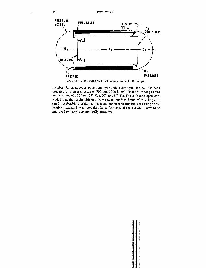
52 FUELCELLS
PRESSUREVESSEL
FUEL CELLS ELECTROLYSISCELLS H2
CONTAINER
H2 02PASSAGE PASSAGES
FIGURE 36.-Integrated dual-stack regenerative fuel cell concept.
member. Using aqueous potassium hydroxide electrolyte, the cell has been
operated at pressures between 700 and 2000 N/cm 2 (1000 to 3000 psi) and
temperatures of 150 ° to 175 ° C. (300 ° to 350 ° F.). The cell's developers con-
cluded that the results obtained from several hundred hours of recychng indi-cated the feasibility of fabricating economic rechargeable fuel cells using no ex-
pensive materials. It was noted that the performance of the cell would have to be
improved to make it economically attractive.

CHAPTER 6
Fuel Cell Technology State-of-the-Art
INTRODUCTION
To summarize the state-of-the-art in a developing technology is never an
easy task, for new developments are apt to make such a summary obsolete in a
short time and rapid growth makes it difficult to ensure exhaustive coverage.
In reviewing fuel-cell terrestrial technology the problem is compounded.
Much of the nonaerospace application work is concerned with the developmentof fuel cells for military applications, and as such is beyond the scope of this
survey. A number of the remaining developmental efforts are aimed at
competitive commerical markets; consequently data, particularly on perfor-
mance and cost, are proprietary in nature and therefore not releasable.Cost data in particular are difficult to establish for fuel cells because of the
special-purpose nature of most of the applications to date. In general, cost has
not been the predominant consideration in these applications, but rather the
development and limited production of a device able to satisfy special
constraints and requirements. Because only a few units have been built for eachapplication, the devices must be regarded as prototypes, not production units,
and are therefore high in cost.
Consequently, this chapter is a general guide to the present status of fuel
cell technology for terrestrial applications. Detailed information on cost,performance, and lifetimes of various fuel cell types will become available as
work currently in progress begins to yield data of this type.
At present, it is valuable to examine the state-of-the-art in fuel cells for
aerospace applications because the time span covered by this work is
sufficiently long to reveal significant improvements in the technology. It would
be unwise to infer that advances of an equal magnitude can be expected interrestrial fuel cell technology, because some of the aerospace cell advances
have already been incorporated into their earthly counterparts; however, it isreasonable to assume that some reduction in cost and volume of future
Earth-bound cells will be realized.
AEROSPACE FUELCELLS
NASA is currently eyeing a fuel cell power supply for the space shuttle, a
reusable vehicle that will ferry crew and supplies between Earth and orbiting
spacecraft or platforms. The design goals for this system call for a 6 to 10-kW
53

54 FUELCELLS
unit with a specific weight in the range of 4.5 to 13.5 kg[kW (10 to 30 lb/kW)and a design lifetime of 5000 to 10 000 hours. The reusable nature of the
shuttle vehicle makes easy and rapid start/stop sequences of the fuel cell a
prime requirement. Under contract to NASA's Manned Spacecraft Center in
Houston, Texas, General Electric and Pratt & Whitney Aircraft are engaged in a
technology demonstration program that will provide a baseline for the shuttlesystem design.
General Electric's approach uses a solid polymer electrolyte (ion-exchangemembrane) of perfluorinated sulfonic acid with platinum black, metal screen
electrodes. Thermal control is achieved by circulating coolant between adjacentanodes, and product water is removed from the wetproofed cathodes by
capillary forces in a wick system similar to that employed in the Gemini fuel
cell. The reactants are hydrogen and oxygen. Cells are constructed in a
back-to-back configuration as in figure 37 to form a bi-cell assembly with atotal active area of 650 cm 2 (0.7 ft 2). Components of a cell assembly are
shown in figure 38.The baseline system is rated at 5 kW and consists of 40 bi-cell assemblies in
two stacks. Nominal operating temperature is 65 ° C. (150 ° F.), but it is
claimed that the system will operate effectively over a wide temperature range.
System output voltages of 28, 56, and 112 Vdc can be supplied by appropriateinterconnection changes. System flexibility is considered by General Electric to
be a major design feature. The baseline module weighs 68 kg (150 lb) and is
packaged in a container of approximately 0.056 m 3 (6 ft 3) excluding controls.Figure 39 illustrates the system in schematic form.
Pratt & Whitney is also studying advanced shuttle fuel cell concepts under
contract to NASA's Lewis Research Center, and has designed a cell capable of
7-kW sustained power that they estimate will weigh only 39 kg (85 lbs). A
mock-up (nonworking model) of the proposed unit, shown in figure 40,
measures 44 x 43 x 22 cm (17-1/2 x 17 x 8-1/2 in.) including controls, giving it
a specific volume of 0.006 ma/kW (0.209 fta/kW). The designers claim that
this device could operate at a peak power level of 50 kW for short periods. A
schematic of the proposed cell is shown in figure 41. This performancerepresents a current design goal and as such must be regarded as beyond thestate-of-the-art.
Both shuttle system designs exhibit significant improvement in specific
weight and volume over previous space fuel cell systems as summarized in table2.
When the space shuttle and intermediate design programs are considered on
the basis of improvement with time, dramatic advances in the technology areforecast, as illustrated in figure 42. Specific weight and volume should decrease
by almost an order of magnitude (figs. 42a, 42b), while operating lifetime
should increase to a similar degree (fig. 42c). During this period, per unit
specific costs ($/kW) may fall to less than half their original value (fig. 42d).
As might be expected, these improvements are reflected in single cell
11

OXYGEN PURGE
STATE-OF-THE-ART
BUS BARS
55
DC POWER OUTPUT
OXYGEN PURGE
HYDROGEN INLETMANIFOLD
SEPARATOR
'GEN GASKET
LON SPACERSCREEN
CIRCULATING
COOLANT
SOLID POLYMERELECTROLYTE
CATHODEELECTRODE
ANODE- ELECTRODE
SOLID POLYMERELECTROLYTE
COOLANTCARTRIDGE ---ASSEMBLY
ANODE SPACESCREEN
__ HYDROGEN INLETMANIFOLD
-- BONDING FRAME
WICKS TOPRODUCT WATER
SEPARATOR0 2 IN
FIGURE 37.-Back-to-back fuel cell assembly schematic.

56 FUEL CELLS
FIGURE 38.-Space shuttle fuel cell assembly.
performance also. A predominant characteristic in fuel cell performance is the
current density that can be sustained without excessive polarization. Foraerospace hydrogen-oxygen cell this has risen from between 31 and 125
nlA/cm 2 (34 to 135 A/ft 2 , (ASF)) to between 200 and 300 mA/cm 2 (216 and
324 ASF) under nominal operating conditions, with peak current densities ashigh as 1 to 2 A/cm 2 (1080 to 2160 AS F) being attainable for short durations.
Specialized cells (ref. 23) have been operated at 2.7 A/cm 2 (2900 ASF), using
open-cycle heat and product water removal. This technique results in high
specific fuel consumption, but high-power density cells such as this might find
application as emergency high-power backup power supplies as well as inmissile and satellite systems.
NONAEROSPACE FUEL CELLS
In terms of development, the most advanced types of cells for terrestrial
applications are those using hydrogen-air and hydrazine-air as reactants. Hydro-
gen-air cells developed directly from hydrogen-oxygen alkaline cells (ref. 24)
have been used with a scrubber system to remove carbon dioxide from the air
supply. The use of air limits the current density attainable in the cell to less
than that achievable by an oxygen-breathing device for a given oxidizer flow
rate, but practical cells have been operated at current densities better than 100
mA/cm 2 (108 ASF) using blower-supplied air (see ch. 7). Specific weights of
10 to 12 kg/kW (22 to 28 lb/kW) are state-of-the-art at specific volumes around
0.03 ma/kW (1 fta/kW). Cells deriving hydrogen from metal hydrides have
been built as portable low-power supplies (ref. 25). Hydrogen is stored in solid
form as lithium hydride or sodium aluminum hydride and released by the
addition of water to the hydride container. Both aqueous alkaline electrolyte
and solid ion-exchange membranes have been used with this type of fuel toachieve system characteristics of 180 kg/kW (400 lb/kV 0 and 0.4 m3/kw (14
fta/kW).
Fuel cells burning hydrazine with oxygen, hydrogen peroxide, or air have
been taken to a fairly advanced stage of development and are currently being
used by the U.S. Army as transportable power supplies in the low-power range
of 50 to 500 watts (ref. 11), and have been used experimentally to power
submersible vessels in the range of 750 to 2000 watts (ref. 12). Performance
Ill l_
i!

STATE-OF-THE-ART 57
Z
z -_
WIIillil
>

58 FUEL CELLS
z
m
FIGURE 40.-Advanced 7-kW hydrogen-oxygen fuel cell powerplant.
parameters in the low-power range indicate specific weights of 60 kg/kW (130
lb/kW) and specific volumes of 0.1 to 0.15 m3/kW (3.5 to 5.5 ft3/kW).
Estimates of cost (ref. 26) for systems of this type produced in quantities of
100 put the price per unit at about $30 000[kW, about an order of magnitude
lower than aerospace hydrogen-oxygen cells of comparable power output.The higher powered systems have been developed (ref. 12) by a French
electrical equipment manufacturer, Alsthom, using a technique that offers
significant potential reductions in manufacturing costs and results in very
compact cell stacks. The nonporous electrodes consist of goffered (finely
fluted) metal sheets a few tenths of a millimeter thick, separated by a
semipermeable membrane (fig. 30). Hydrazine and hydrogen peroxide reac-
tants dissolved in the electrolyte are circulated through the half-ceils thusformed. The electrodes are made from 50# sheets of nickel or stainless steel
resulting in complete cells about 0.5-mm thick. Catalysts of cobalt or silver
mixed with an adhesive resin are applied to the electrodes, which are then
mounted in thin plastic frames. The method of assembly, illustrated in figure
43, permits the construction of very compact systems. Cell stacks of this type
have achieved power densities of 0.001 ma/kW (0.0035 ft3/kW) at a specific
weight of 2 kg]kW (4.4 lb/kW), and complete systems weigh 10 to 15 kg/kW
with 4 kg/kW considered a feasible goal.

COUPLEDREGULATORS
REACTANTPURIFIERS
ACCUMULATOR
CELLSTACK
EVAPORATIVECOOLERS
STATE-OF-THE-ART
WATER
IN OUT
CONDENSER
WATERVAPORCAVITIES
59
ooo..TUT
_VENT
FIGURE 41.-Schematic of advanced 7-kW fuel cell.
"l LI
!
E
4,.
FIGURE 42.-Improvements in performance of hydrogen-oxygen fuel cells for aerospace
applications, including projections.
499-155 0 - 73 - 5

60 FUEL CELLS
TABLE 2.-Aerospace Fuel Cell Performance Gains
System Apollo Gemini Space Shuttle
Power level (kW) 1.0 1.0 5(rated)
Specific weight, kg/kW 115 30.8 13.6(lb/kW) (250) (68) (30)
Specific volume, ma/kW 0.167 0.051 0.034(ft3/kW) (5.9) (1.8) (1.2)
Methanol-air fuel cells are also under development by Alsthom under a joint
program with Esso Research and Engineering Company. The initial objective of
the development program, which was begun in December 1970, is the
development of a practical fuel cell system that would be competitive with
small engine generators and batteries satisfying specialty and remote power
requirements. The development of a fuel cell system for automotive propulsioncould follow if the initial objective is achieved. Esso refuses to release
information about the program on the grounds that all aspects are proprietary.Alsthom admits (ref. 12) that the use of methanol in the hydrazine-type cell
structure still requires extensive fundamental work, particularly in connection
with the development of cheap catalysts. Under the terms of the Alsthom-Esso
agreement, Esso will contribute catalyst technology and conduct programs
aimed at developing new and improved catalysts.The most active development of hydrocarbon-burning cells is being
undertaken by Pratt & Whitney for a consortium of gas and electric utility
companies known as TARGET (see ch. 7). Developmental powerplants are
currently undergoing field tests using methane and air as reactants. Themethane is reformed externally with steam and the products are reacted in cells
using phosphoric acid electrolyte.An internal-reforming methane cell has been developed jointly by Bolt,
Beranek, and Newman, Inc. and Atlantic Richfield Co. (ref. 19). Operating at
5t0 ° C. (950 ° F.) and atmospheric pressure, the cell uses a molten alkaline
electrolyte of sodium and potassium hydroxides. Methane (or, it is claimed,
other hydrocarbon fuels) is reformed on a catalytic bed of nickel in a chamber
adjacent to a palladium anode. Hydrogen formed in the chamber diffuses
through the solid anode to react with the electrolyte. Air from which CO2 hasbeen removed is admitted to the cell on the cathode side. As it enters it agitates
the electrolyte around the nickel screen cathode, forming a superoxide thatfacilitates the reduction process. Current densities as high as 600 mA]cm _ (648
ASF) of anode area at 0.6 volt are claimed for the cell operating on methane
and air, and laboratory operation over 3500 hours is reported. The developers
emphasize that considerable engineering and system development must be done
before potential advantages and costs for commercial or industrial applications
1ii:!
I

STATE-OF-TIlE-ART 61
o
,d
E0o
E0
I_4
°
\
\\

62 FUEL CELLS
can be assessed. The companies are considering third-party licenses toaccelerate this work.
FUELCELLCOSTS
Although it is difficult to establish reliable cost figures for contemporaryfuel cells, some approximations may be made. Fabrication costs for aerospace
fuel cells lie in the range $100 000 to $400 000 per kilowatt, the former figure
reflecting the cost of more recent designs. Fuel cells developed for militaryapplications are estimated (ref. 11) to cost about $30 000 per kilowatt, with a
figure of $I0 000 per kilowatt considered a feasible goal. It seems probable
that these high figures are a reflection of the limited quantities produced and
the requirements for compact, lightweight devices in both applications. In
contrast, developers are believed to have set a goal of $100 to $300 per
kilowatt for stationary hydrocarbon-burning powerplants in the 10- to 15-kW
range, while some economists (ref. 27) are of the opinion that fuel cell
powerplants cannot attain economic parity in low- to medium-power (20 to
200 kW) commercial applications unless the investment cost drops to about
$10 to $30 per kilowatt. These costs are summarized in figure 44, from which
it is obvious that drastic cost reductions are necessary if the fuel cell is to
achieve general application.
Two expensive elements in contemporary fuel cells are electrodes and the
catalysts incorporated into them, while complex assembly techniques add
further to their cost. Current design practices use several innovative techniques
that significantly reduce costs, and these are worth examining at this point.Four approaches may be taken to reducing catalyst costs; the use of less
expensive catalysts, more efficient utilization of those employed, andreduction in the amount of catalyst used (catalyst loading and use of a more
effective catalyst). Considerable effort has been expended in the search for
cheaper catalysts (i.e., cheaper than the commonly used platinum), and alloys ofgold, palladium, and other noble metals have been found to be useful in certain
applications. No real breakthrough in catalyst cost reduction has been
announced, although it is possible that such advances have been made byprivate concerns. Such discoveries would be regarded as proprietary.
Reductions have been made in the amount of catalyst used in fuel cells byputting it only where needed and using it more efficiently. Figure 45 illustrates
how this might be done in a sintered electrode. In early electrodes, catalysts
were mixed with the electrode material as shown in figure 45a. Only thesurface of each catalyst granule can contribute to the fuel cell reaction so the
majority of it is wasted. Likewise, the catalyst located at the outer faces of the
electrode is exposed only to the reactant or the electrolyte, but not to both at
once where the reaction takes place. Consequently, it too is wasted. By coating
inert granules with a thin layer of catalyst and confining these active granules
ii!
]i il
il
it ii
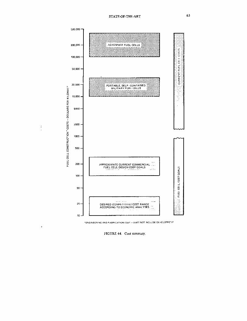
STATE-OF-THE-ART 63
5oo,ooo -
200.000 ==
100.000 --
50.0<)0-
20.000 --
10.00t3 --
a.
_ 5000 --
5
O
I
m
2000-O(J
0-- I000 --
z 500--
8J
_ 200--
100-
50-
20--
10-
l;_;_i ;o_:i,;;Z SE,S:coNT;,'NEO_;;il
i_':II:I_':::;!:;:_ MI LITA BY FUEL CEL LS _'I!:'It
APPROXIMATE CURRENT COMMERCIAL Z
FUEL CELL DESIGN COST GOALS
.......
DESIRED COMPETITIVE) COST RANGE
ACCORDING TO ECONOMIC ANALYSES
• ENGINEERING AND FABRICATION COST DOES NOT INCLUDE DEVELOPMENT
i:F+:.:.i:i
-:'1 F-" ,:.FF V_ :-1•1": 0 ":"!:i:u i:_.:.: ,,J .:.F:, .J :-:,,., L,LJ":
-:-: .,,J .:.
:,:. la.. :,::::: I'-- ::: ":::: z :::,:.: LU .:.:::: E: 1:::
i .!
!1i--- i
il
:..:.: !
FIGURE 44. Cost summary.

64 FUEL CELLS
' I
o____.o o2__ 'Zl._c_.o_
Z
ECTROD
a. b,
ELECTRODE MATERIAL
CATALYST
CATALYST COATED MATERIAL
FIGURE 45.-Reduction in catalyst inventory by coating and localization.
to the reaction zone of the electrode (fig. 45b), the amount of catalyst used is
considerably reduced without any loss in reactivity.
As understanding of the fuel cell improves and construction experience
grows, cheaper electrodes will become possible. Reduction in the complexity
and number of process steps during electrode construction has already yielded
significant cost reduction in existing fuel cells, and careful design of the
electrode and its mounting frame may greatly simplify the assembly of the fuel
cell stack. When these techniques are employed in conjunction with relatively
large-scale production, cost reductions on the order required are not entirelyinfeasible.
i
ii]

CHAPTER 7
Applications of Fuel Cells
INTRODUCTION
The relatively high cost of the fuel cell as a power-generation device has
limited its application so far to special circumstances having requirements that
the fuel cell was able to satisfy, usually by virtue of its high efficiency and
consequent low weight, low volume, or low specific fuel consumption. Thus, as
a power supply for submersibles, spacecraft, and remotely located repeater
stations, it offers special advantages that offset its high cost and othershortcomings. These same advantages have led to the consideration of fuel cells
in a number of other specialized applications including portable power supplies
and biomedical power devices. Some of these are listed in table 3 as
special-purpose applications.
Although the fuel cell finds most immediate application in these specialized
areas, it could play more general roles, providing some of the shortcomings canbe eliminated. The general-purpose requirements in table 3 are more difficult
to meet, particularly regarding economy and lifetime. However, more general.
applications represent very large markets in comparison with the limited-
production special applications. That factor has already prompted the
investment of large sums of money in research and development for vehicular
propulsion and domestic power.
In most of the proposed applications the fuel cell would function as a
power-conversion device, as might be expected. In others, however, the
improvements in ion-exchange and electrocatalysis technologies would be
exploited not in power-conversion techniques but in the purification or
concentration of liquids and gases. In this way, elements of fuel cell technology
might be employed as oxygen generators or concentrators in hospitals and
aircraft; as dialysis membranes in artificial kidney machines; and in environ-
mental control systems as air cleaners and dehumidifiers, water purifiers, and
perhaps as desalination plants.Fuel cells are currently being operated in or developed for a number of
diverse applications. In none of these is the fuel cell a production unit, but
rather an engineering model being used to determine the nature and extent of
the problems encountered in practical operation and to examine the feasibility,from a technical and economic aspect, of using fuel cells in each role.
An examination of some of these projects is of value, since it illustrates the
types of problems that must be overcome and the very different approaches
65

TABLE 3.-Potential Fuel Cell Applications
SPECIAL-PURPOSE
Remote Power
Communications repeaters
Automatic weather]oceanographic
stations
Navigational aids
Pipeline cathodic corrosion protectionand instrumentation
Remote signal and beacon devices
Off-shore platforms
Emergency and Standby Power
Hospitals
Civil defense installations
Radio, television, and telephoneservices
Police stations
Fire and intrusion protection
Aircraft
Portable Power
Two-way communications Search and rescue
Lighting Battery charging
Heating
Propulsion
Underwater rescue and exploration
Silent power for search and rescue
vessels
Forklift trucks
Off-road vehicles
Special low-pollution vehicles
Other
Biomedical power
Emergency oxygen for hospitals,
aircraft
Desalination
Dialysis (artificial kidney machines, etc.)
Environmental control
GENERAL-PURPOSE
Utility Power
Domestic power supplies Power distribution sites
Commercial and industrial installations Central generating plant
Peak demand power storage
Propulsion
Low-pollution, low-noise urban
automobiles
Hybrid power plant highway vehicles
Electric drives for boats
Locomotives
Mass transit vehicles
Recreation
Personal portable power for beach, mountains, etc.
Transportable power for camping, trailers, etc.
Silent power for naturalists, fisherman

APPLICATIONS OF FUEL CELLS 67
that each application requires. The examples chosen do not comprise an
exhaustive list of current applications but rather are selected to illustrate the
variety in requirements, environments, and power levels under consideration.
The first is an outstanding example of a specialized application, the
proposed use of a fuel cell as a biomedical powerplant to drive an artificial heart.
It vividly illustrates the extreme diversity of potential applications and at the
same time provides insight into the problems that must be faced in adaptingfuel cells to unusual environments.
The second example describes an effort to develop and evaluate a fuel cell
suitable for use in the home. Trial installations have already been made at the
time of writing, and the results of these tests may well decide the future of fuel
cells in this type of role.Finally, the application of fuel cells to general automotive propulsion is
examined through two examples. The first describes the development of a
sophisticated hydrogen-oxygen-fueled system by General Motors incorporating
several advanced technological concepts. The second example reviews a more
successful, if less spectacular, "do-it-yourselr' effort using a combination of
hydrogen-air fuel cells and lead-acid batteries.
A FUEL CELL ARTIFICIAL HEART POWER SUPPLY
Blood pumps to assist or replace the heart have been the subject of
considerable development effort for several years, and used with some success
in animal and clinical experiments (ref. 28). For use over extended periods andduring heightened activity, the provision of a suitable power source is a
significant problem. To permit the patient to lead a normal life, the power
source must be implantable within the body, or must store energy periodically
transmitted into the body, preferably through the skin. This problem is being
addressed on a broad front by a number of technical approaches. Candidate
power sources under consideration include batteries charged by percutaneoustransformers, thermoelectric generators powered by isotope heat sources,
piezoelectric actuators, reciprocating engines, and fuel cells.
Design Considerations
Investigators have examined (ref. 29) the problem of powering an artificial
heart by an implanted fuel cell, and have defined some of the problems
inherent in such a project (refs. 30, 31). The limitations of an implanted fuel
cell, together with the desirable redundancy of two power sources, have led to
the consideration of a hybrid fuel cell/battery system (refs. 31,32).
The output of an implantable fuel cell for this purpose should be 4 to 5
watts, with peak power requirements (up to 10 watts) being met by a
supplementary and backup nickel-cadmium battery. To be implantable thedevice must occupy a volume of no more than 250 cc (15 in. 3) and weigh less

68 FUELCELLS
than1.4 kg (3 lb). It must be made from blood- and tissue-compatible
materials and must not give off unmanageable quantities of heat or wasteproducts or products that are toxic. Finally, it must operate on reactants that
are available within the body.
Performance Limitations
Opinions differ on the design of the fuel cell, but there is general agreement
on the reactants that it must use. Glucose is regarded as the best available fuel,
since it is plentiful and readily oxidized. Oxygen from the bloodstream is
usually considered as the oxidizer and blood plasma as the electrolyte.
Five problems are encountered immediately:
(1) Glucose and oxygen is not a particularly high-energy combination in a
fuel cell because complete oxidation represented by C6 O6HI 2 + 6H2 o _ 6CO2+ 24 H + + 24 e- does not occur in practice; instead gluconic acid is the
byproduct, yielding only two electrons:
C606H12 -_ C606H10 + 2H + + 2e-
(2) The plasma is neutral (pH = 7.4), giving rise to high concentration
gradients due to its poor buffering capacity and slowing the cathode reaction,
wliich progresses much more rapidly in acid or alkaline conditions.
(3) Solubility of oxygen from oxyhemoglobin in blood plasma is poor andresults in very low concentrations, about 2 percent by weight, of the available
oxidizable organic fuel species.
(4) Catalysts that are best suited to activating the glucose oxidation
reaction are susceptible to poisoning by proteins in the blood plasma.
(5) The presence of both fuel and oxidizer in the supply stream may give
rise to opposing potentials at the cathode if the fuel is allowed to react there
also, further reducing its already poor performance.
Not much can be done about limitations (1) and (2). Glucose and oxygen
represent the best available reactants, and must be accepted despite poor
performance. The neutrality of the plasma cannot be altered, since the body
vigorously opposes any change in pH by several mechanisms.
Approaches to designing a fuel cell with the desired performance have
addressed some of the other limitations. To overcome the low oxygen
concentration (3), the use of an air-breathing cathode has been suggested (ref.
31), in which air from outside the body would be caused to flow through the
cell in a pulsating mode. A small balloon implanted on the opposite side of the
diaphragm from the air inlet would act as a pump for this purpose. The
possibility of bacterial ingress and subsequent infection is a danger with this
approach. Other workers (ref. 29) have proposed the use of flow-through
electrodes to reduce the mass transport problems inherent in surface contact
electrodes due to limitation (2). Fuel reactions at the cathode (5) might be
Ii i !
i!

APPLICATIONS OF FUEL CELLS 69
overcome by using a selective catalyst that supports only the required
reactions, but such a catalyst has not been identified.
A general design goal for the fuel cell has been a current density of about 4
to 5 mA/cm 2 (projected area) at 0.5 to 0.6 volt. This figure would permit the
generation of the required power in the available volume, assuming a total
electrode thickness of about 1 mm (1/25 in.). Difficulty has been experienced
in attaining and maintaining this current density.
A Design Concept
A somewhat different approach to the problem has been taken by Dr. Jose
Giner and coworkers at Tyco Laboratories. Accepting some of the inherent
limitations in an implantable fuel cell, this team has established a design goal ofonly I mA/cm 2, having determined to their own satisfaction, by experiment
and analysis, that such a goal is achievable (ref. 32). It is proposed to make up
the loss in performance by using extremely thin cells about 250/1 (about 1/100in.) thick (1 /a = one micron = 1/1000 millimeter). The construction of such
cells has verified the feasibility of the concept and tests are currently under
way on experimental cells.
The concept proposes the use of glucose and oxygen as the reactants in a
hybrid fuel cell/battery system, the goal being a 5-watt fuel cell occupying
about 250 cc (15 in.3). The peculiar characteristic of the cell is in its
configuration (figure 46).
Blood is supplied through specially constructed channels lying between
adjacent cells. Both electrodes are faced with selective membranes that allow
only glucose through to the anode and only oxygen to the cathode. The blood
channels are molded into the oxygen membrane so that the cell benefits from
additional oxygen extraction area. There are thus five components in intimate
contact with each other: a glucose-selective permeable membrane, a porous
glucose electrode (anode), an electrolyte matrix or separator, an oxygen-elec-
trode (cathode), and an oxygen-selective permeable membrane incorporating
the blood supply channels.
The advantages claimed for the concept are that the blood does not contact
the electrodes, thereby avoiding clotting problems and catalyst poisoning, and
that the desired performance may be attained at low current densities (due to
the high packing factor) and without any major technical breakthrough.
Cell Construction
Oxygen electrodes for the cell are formed from PTFE-bonded platinum
black with a flat gold grid embedded as a current collector. The gold grid is
prepared by photoetching techniques similar to those employed in the

70 FUEL CELLS
A. GLUCOSE-SELECTIVE
PERMEABLE MEMBRANE ........
B. POROUS GLUCOSE ANODE
C. ELECTROLYTIC
SEPARATOR
D. HYDROPHOBIC AIR
CATHODE
E. OXYGEN-PERMEABLE
MEMBRANE
F. BLOODCHANNEL
G,
H.
BLOOD-COMPATIBLE
SURFACE TREATMENT
GLUCOSE MEMBRANE
OF ADJACENT CELL
°_
tlIJ
#1'/¢'l L
5,1'#
:W
-J,
N
iii
:N,'TJ
,',J'/
Fl#t
't4,'a
.. ii
"/] r:.__pT#
,°.l/
O't4
..°
_XX)KXX>
KXX><)<>0
<XX>
<XX>
(XX)d
<XX__
(XX)_
k 7. i. x
_'XXX
kA A _
....... _F
XXX _, ;,zt_
44,
_XX."
_XX)
_XX)
• ;id
KXX),
•..-..-.; ,f,'
<.x.x.) _,'t,CXX_ ,,t'_
,(XX> "..'I
FIGURE 46.-Magnified cross-section of a single cell of artificial heart
(blood flow perpendicular to plane of paper).
,---.--
,?;'
t,7
,2
IF-
.,¢ •
"9,
power supply
manufacture of printed circuits for electronics. To make the electrode, PTFE is
sprayed onto aluminum foil and sintered. A mixture of platinum black and
PTFE is then sprayed over this first layer, the gold grid pressed into it, and the
,i
[I! i

APPLICATIONS OF FUEL CELLS 71
remaining platinum/PTFE mix applied. The electrode is then dried andsintered, and the aluminum foil etched away in dilute KOH. The resulting
electrode has a thickness of 150 to 230/1 (6 to 9 mils; 1 rail = 1/1000 in.) and
a catalyst loading of 13 to 17 mg/cm 2 .
Glucose electrodes have been made both as separate components and as
films formed directly on the separator material. Independent electrodes are
formed by pasting a mix of platinum black and asbestos onto a gold grid
formed as for the cathode. They have thicknesses of 1O0 to 127/a (4 to 5 mils)
and catalyst loading of 9 mg/cm 2 . Alternative construction uses 90 ta (3.5 mils)
separator material onto which gold is evaporated, followed by the deposition
of platinum black. This results in an electrode/separator combination 100/a (4
mils) thick with 13 mg of platinum per cm 2 . When the independent electrodes
are used, separator materials 13/a (0.5 rail) thick are employed.Glucose permeable membranes of a cellulose material 13/a (0.5 mil) thick
have been used. Collagen membranes 25 /a (1 rail) thick have also beenconsidered.
Oxygen membranes of commercially available dimethylsilicone 25 # (1 rail)
thick have been used as independent components, and alternate membranes of
dimethylsilicone-polycarbonate copolymers have been formed directly on the
back of the oxygen electrode.The blood channel structure required for the cell has been formed by two
processes; molding of silicone rubber and hot-pressing of PTFE. Both
techniques require a mold of the channel structure, which has been made both
by precision machining and photoetching techniques. A minimum groove size
of 100/a (1/250 in.) has been selected based on the size of the largest white
blood cells (20 /a) and from practical considerations of construction and
pressure loss.Figure 47a shows a magnified cross-section of the channel structure formed
by molding silicone rubber. In figure 47b, the channels formed by pressing
porous PTFE are shown in a scanning electron micrograph. Good structural
integrity and uniformity are displayed in both techniques, and both can be
covered with an ultrathin layer of dimethylsilicone-polycarbonate copolymers
as a blood-compatibility treatment.
By combining techniques it has been possible to construct integratedmultielement units. A PTFE-bonded platinum electrode was formed on the
back of a PTFE channel-structure component. The front of the channel
structure was then spray-coated with the oxygen permeable membrane. The
integral membrane/channel structure/electrode unit is shown in cross-section in
figure 47c. It is claimed that such techniques hold promise for reducing theoverall cell thickness.
The components currently employed result in a cell thickness of about 400to 500/a. With refinement the goal of 250/1 is believed to be attainable. In
table 4 the goals for individual component thicknesses are listed and thedimensions of the fuel cell array given.

72 FUEL CELLS
a. Cross-Section of Channels Molded in Silicone Rubber.
100 p
Channels Formed by Pressing Porous PTFE
(p(_lytct r_fflu_)r octhyIcnc ).
100
Cross-Section Through Integral Membrane/Channel
Structure Electrode Unit,
FIGURE 47.--Blood channel construction techniques.

APPLICATIONS OF FUEL CELLS 73
TABLE 4-Implantable Fuel Cell
Design Parameters
Component Thickness,/_
02 - membrane 12
02 - electrode 50Separator 22Glucose electrode 40
Glucose-membrane 20
Blood channel 100
Cell total thickness (goal) 244
Cell size = 10 cm X 5 cm200 cells @ 250 u = 5 cmCell stack volume = 10 cm X 5 cm X 5 cm = 250 ccExchange surface = 200 X 10 cm X 5 cm = 10000 cm 2Current @ I mA/cm 2 = 10 APower @ 0.5 V = 5 watts
Cell Performance
Tests to date have proven the concept feasibility, but current densities
achieved so far are well below the goal of I mA/cm 2. In addition, slow
degradation in the performance of the glucose electrode has been observed due
to byproduct contamination, but it has been shown that the original electrode
activity is restored by short-term polarization. In an implanted fuel cell, this
might be achieved by connecting the supplementary nickel-cadmium battery
directly across the fuel cell for a short time. This would have to be done, of
course, when the patient was resting since power to the artificial heart would
be momentarily reduced or interrupted.
It is suspected that glucose and/or other oxidizable products are diffusing to
the PTFE/platinum cathode and being oxidized, lowering the potential of the
electrode and reducing the amount of oxygen available for the reaction. This
may be reduced either by using an oxidation catalyst that is inactive to glucose
(such as gold black or gold-based alloy blacks), or by the use of a separator
which does not permit the passage of the interfering species. In selecting a
separator, a tradeoff must be made between low transport of interfering
reactants and high ion mobility.
FUEL CELLS FOR DOMESTIC POWER SUPPLY
Introduction
The vision of a fuel cell that could provide electricity for domestic
consumption spurred much of the development effort between 1890 and 1950
(see ch. 2). In 1897, Dr. W. A. Jaques published (ref. 33) data on a domestic
fuel cell that he had developed based on the earlier work of Bequerel and

74 FUEL CELLS
Jablochkoff. His cel/, enclosed in a massive brick structure, operated on carbon
and air at a reported efficiency of 82 percent. It was later revealed that the
performance was due to the formation of hydrogen by an electrolyte-anode
reaction, and that the real efficiency was in fact much lower. Moreover, the cellused pure carbon rather than the economical coal fuel for which it was intended.
Coal-fired fuel cells have been studied since Jaques' work using pure coal
dust, but with only limited success. With the changing emphasis on fuel
reserves, interest has naturally turned to fuel cells burning hydrocarbon fuels.
The technical problems experienced in building this type of cell are discussedin chapter 5. However, the problem is not solely a technical one, for if fuel
cells are to attain widespread use on the domestic power market they must be
economically competitive and socially acceptable. Many believe the fuel cellholds promise in both these areas.
Its theoretically higher efficiency in comparison with thermal dynamic
systems is the basis on which economic superiority might be attained, but the
realization of this potential is not simple. The most economic fuels are not
those the fuel cell is best able to use, and most current manufacturingtechniques result in fuel cells that are expensive pieces of equipment. To these
factors must be added the requirements of long life and reliable unattended
operation common to all domestic appliances. The economics of fuel cell
applications have been studied in detail (refs. 27, 34), and these factors are
clearly recognized. Not so clearly appreciated are the less tangible, but equally
important, factors surrounding the social acceptability of the fuel cell. Here
again it holds advantages over competitive methods of power generation-intheory, if not in practice. Higher efficiency means better utilization of fuels
and, therefore, conservation of natural resources. The efficiency of the fuel cell
reaction also implies more complete combustion and, thus, exhaust products
that are low in pollutants. Direct conversion from chemical energy to
electricity should result in less waste heat (another environmental pollutant)
and possibly freedom from the noise and vibration inherent in reciprocating
and rotating converters.
However, the highly developed hydrogen-oxygen fuel cell that embodies
these characteristics to a large degree is in conflict with the economic
requirements of an inexpensive machine using cheap fuels. When a fuel cell is
built to use cheap fuels, it loses some of its inherent advantages. Its efficiency
and lifetime are reduced, its pollutants (thermal and gaseous) tend to increase,
and it requires auxiliary components that generate some noise and vibration.
Despite these problems, the potential benefits of a fuel ceil domestic power
system have encouraged continuing appraisals.
Domestic Fuel Cell Trials
One such appraisal resulted in 1967 in the formation of a consortium of gas
utility companies known as the Team to Advance Research for Gas Energy

APPLICATIONSOFFUELCELLS 75
Transformation(TARGET).Theconsortiumformulatedathree-phase,9-yearprogramwith the ultimate goal of establishing a fuel cell energy service, should
such a service prove to be attainable. Pratt & Whitney Aircraft was selected as
the prime contractor for the program.
Phase I, which explored the technical and economic aspects of the service
and established requirements, was completed in 1969. Phase II, in progress at
this time (August 1972), includes continued technology development and the
production of about 60 experimental powerplants for field testing. These trial
units are being used in TARGET's Comprehensive Installation Program, during
which installations are being made in single-family homes, apartments, stores,restaurants, office buildings, and at industrial sites. In addition, fuel cell
powerplants will be installed at two electric system substations. The perfor-
mance of the fuel cell powerplant will be monitored over a period of about 3months at each site under actual service conditions. The purpose of these trials
is to obtain essential data to define the technical, economic, and business
factors affecting the operation of a fuel cell energy service. It is hoped to
identify potential problems in relation to building and utility codes, insurance,
reliability and maintenance, response to peak load demands, and other factors.
The PC-11 powerplant designed and built by Pratt & Whitney is rated at
12-1/2-kW nominal power output and is roughly the size of a household
furnace unit (fig. 48). The powerplant consists of three elements: a reformer, afuel cell, and an inverter. The fuel cell and reformer are housed in a single unit
(fig. 49), and the inverter is a separate, slightly smaller unit.
The powerplant operation is represented schematically in figure 50.
Methane enters the reformer where it is converted to hydrogen and carbondioxide. This gas mixture is fed to the fuel cell anode, and air is supplied to the
cathode. Direct current power from the fuel cell is converted to alternating
current in the solid-state inverter to match the household power requirements.
The fuel cell uses phosphoric acid electrolyte immobilized in a matrix-type
separator between the electrodes. The use of an acid electrolyte avoids the
problems of carbonate formation inherent in alkaline electrolyte cells andeliminates the need for a scrubber to remove the carbon dioxide in the
reformed or "processed" fuel. The electrolyte matrix is contained betweenthin, flexible electrodes in a picture frame gasket (fig. 51). The ceils thus
formed are stacked between molded separator plates that form the reactant
supply channels. Details of electrode construction and the catalyst type(s) and
loading are not available, as this information is proprietary. It is claimed that
the package volume of the fuel cell reformer may be significantly reduced by
rearrangement of the components and some minor redesign. The developers say
that if the powerplant is put into commercial service this unit will occupy
approximately one quarter the volume of the present unit. A size comparison
of the trial unit and the "production" unit may be made from figure 52.
Spokesmen for TARGET are cautious in making predictions about the
future of the fuel energy service, saying only that if the program is successful
499-|55 0 - 73 - 6

76 FUEL CELLS
FIGURE 48.-PC-11 12-1/2-kW hydrocarbon fuel cell powerplant. (Reformer and fuel cellare in the left-hand unit, inverter on the right.)
such a service might be implemented about 1975. The ultimate application of
the fuel cell is considered to be in a "total energy and environmental
conditioning" (TEEC) role, in which the system would provide not only
electrical energy but also heat; would humidify and purify the air; and would
possibly be used as a waste processor. It is felt that such a system might beavailable at the end of this decade. These claims are made with caution,
however. TARGET and Pratt & Whitney have invested $50 million in the first
two phases of the program and expect to invest much more if the decision ismade to continue with Phase III. This commitment reflects the potential
benefits that might be expected to accrue to a viable system, but the
developers stress that many problems remain unsolved and many questionsunanswered at this time.
AUTOMOTIVE POWER APPLICATIONS
In troduc tion
Growing concern over the air pollution contribution of the conventionalautomobile in the midsixties (ref. 35) was accompanied by a search for
alternatives to the gasoline engine (ref. 36). Among the solutions proposed was
a return to the electrically powered automobile (refs. 37, 38), and this has
!ii
ilJ i
:7

APPLICATIONS OF FUEL CELLS 77
®
FIGURE 49.-PC-11 unit with cover removed showing fxael cell (left) and reformer.
resulted in an evaluation of several technological innovations that could make
that goal achievable. The fuel cell is one of the devices considered for this
application.
The use of a fuel cell a_ a vehicular propulsion power unit is not new,
although the field of demonstration has usually been restricted to off-road
vehicles (agricultural and construction machinery, forklift trucks) or special-
purpose commercial vehicles with limited range requirements (delivery vehicles,

78
NATURAL
GASREFORMER
t
FUEL CELLS
AIR
PROCESSED DC
GAS
FUEL CELL _ INVERTER
JHEAT
FIGURE 50.-Operation of the PC-11 powerplant.
ACPOWERv
SINGLE FUEL CELL
;IATOR PLATE
FUEL ELECTRODE
ELECTROLYTEMATRIX
AIR ELECTRODE
SEPARATORPLATE
FIGURE 51.-Typical PC-11 fuel cell assembly.
short-haul transportation, etc.). The extension of fuel cell power to pri-
vate automobiles is recognized as a serious challenge, and a number of
analyses have indicated that to provide the same performance as a conventional

APPLICATIONSOFFUELCELLS 79
ADVANCEDPOWERPLANT1971 DESIGN
TARGET FIELD TEST POWERPLANT1968 DESIGN
FIGURE 52.-Size comparison between 1968 field test fuel cell and 1971 advancedcompact model
internal combustion engine in a regular size vehicle, a fuel cell with
state-of-the-art capabilities would have to weigh more than the car (ref. 39).
However, it is pointed out that the conventional automobile is grossly
over-powered, the engine being sized to satisfy the peak, rather than the
average, power demand. Since this factor contributes to air pollution, it is
reasoned that a reduction in performance is a price that must be paid for
cleaner air. It is not clear whether the driving public is prepared to accept this
penalty, but if one accepts reduced automobile power as a premise, then
perhaps fuel cells could be engineered into effective powerplants for private
vehicles.
Taking another approach, several workers have proposed hybrid power-
plants comprising fuel cells and batteries-the batteries providing the peak
power and the fuel cells acting as charging units during low power demand
periods. If this approach is combined with an acceptance of somewhat lower
performance, the fuel cell might provide an engineering solution to the
problem.
Several vehicular fuel cell and fuel ceil/battery power systems have been
built and demonstrated, but mainly for military vehicles (ref. 40) and
special-purpose vehicles (ref. 41) with limited range requirements. Two
applications to passenger-type vehicles are worthy of note, however. The

80 FUEL CELLS
contrast between these two endeavors is significant; the first being an aU-out
assault on the problem by General Motors Corporation, the second a private
venture by a fuel cell research technologist.
A Fuel Cell-Powered Van
In 1964, the Power Development Group of GMC began a program (ref. 42)
to build and test several electric vehicles with the objective of establishing
development goals for various drive components such as electric motors, motor
controls, and power sources. One of the vehicles was to be powered by a fuel
cell system without batteries.
A GMC van weighing 1476 kg (3250 lb) (fig. 53) was selected for the testvehicle because it offered ample space for the fuel cell system which was
expected to be bulky. The major parts of the system (fuel cells and drive train)were accommodated under the floor, but the reactant storage tanks were
located within the body in a specially constructed space between two bench
seats (fig. 54).
System Description
The drive motor was a specially developed 125-hp, four-pole, three-phase,oil-cooled induction motor designed to operate at 13 700 rpm. A sophisticated
electronic control system using oil-cooled silicon-controlled rectifiers was
employed. These components represented an attempt to apply the most
advanced technology to the program, an objective considered in keeping with
the use of a fuel cell power source.
FIGURE 53.-A fuel cell-powered van.

APPLICATIONSOFFUELCELLS 81
FIGURE54.-Phantomviewofelectrovanshowingarrangementofmajorcomponents.
ThefuelcellsystemwasassembledbyGMCfrommodulesdevelopedandbuiltbyUnionCarbideCorporation(refs.43,44).Operatingonhydrogenandoxygen,thesystemhadaratedoutputof 32kWandapeakpowercapabilityof 160 kW.It usedaqueouspotassiumhydroxideelectrolytethat wascirculatedthroughthecellandthroughaheatexchangerto providethermalcontrol.Waterwascarriedfromthecellsin thehydrogenstreamandremovedinacondenser.Normaloperatingtemperaturewas65° to 70°C.Figure55isaschematicofthesystem.
Thefuelcellstackcomprised32modules,eachhavinganominalpowerratingof 1kW.Eachmodulecontained68cellsconnectedin 17seriesstringsof fourparallelcells.The321cm2 (0.346ft2) electrodeswereof 0.2-mm(0.008-in.)thickporousnickel,to onesurfaceofwhichwasapplied0.4to0.5mm(15to 20mils)of gradedlayersof activatedcarbon,wetproofingagents,andcatalysts.Thedesignof thistypeofelectrodeisdescribedinreference45.
Cellconstructionis detailedin figure56a.Oneanodeandcathodewerebondedto a polysulfoneframeto formanelectrolytesandwich,1.27-mm(50-mil)cellspacingbeingmaintainedbyaplasticmesh.Moldedintotheframeweresixlongitudinalpassagesforsupplyandreturnofhydrogen,oxygen,andelectrolyte.Narrowpassagesconnectedthesemanifoldswiththeinterelectrodecavities.Thedimensionsof thepassageswerechosencarefullyto providesufficientelectricalresistanceto limit intercell leakage currents through theelectrolyte and ensure uniform flow. Cell sandwiches thus formed were stacked
anode-to-anode and cathode-to-cathode, spaced, and sealed by a neoprene
gasket forming the hydrogen and oxygen cavities. Epoxy-fiberglass end, top,

82 FUEL CELLS
i VE NT
SOLENOID RESERVOIR --_
VAPORIZERS\
- + tBURST [ REGULATOR I
k_I'_,, . l_I"l -_ _Low_[Ii
CONDENSER I
EXHAUST
WATER
FINNED
',',+','?,',',2,
COOLER _ AIR
0
FIGURE 55.-Schematic of the electrovan fluid system showing four fluid loops:
hydrogen, oxygen, electrolyte and air.
and bottom t_]ates provided mechanical pressure to seal the stack. The sides of
the stack were potted in epoxy resin after making the intercell electrical
connections (fig. 56b). The technique resulted in a clean, compact, leakproof
stack of approximately 0.028 m 3 (1 ft3).
System Problems
Among the major problems encountered were the weight of the fuel cell
system and the high parasitic loads encountered. The complete fuel cell system
weighed 1534 kg (3380 lb), more than the basic GMC van in which it wasinstalled. The dry modules accounted for 40 percent of this weight, the
accessories 44 percent, and the electrolyte 16 percent. A detailed weight
summary is given in table 5. The parasitic losses amounted to 5.4 kW, 3 kW
being required to drive the accessories (pumps, fans, etc.) and 2.4 kW being lost
in electrolyte leakage currents.
Performance
The fuel cell-powered van weighed 3220 kg (7100 lb), more than twice the
weight of the standard version. Although full power tests were not conducted
I!Iif! +ii!
ii
ili +
+ii i_+!{ i+

APPLICATIONS OF FUEL CELLS 83
_C_OROGE_-
E NO _
(A)
OASK_r
A_
FIGURE 56.-Electrovan fuel cell. (A) Exploded view of fuel cell. (B) 1-kW fuel cellmodule.

84 FUEL CELLS
TABLE 5.-Fuel Cell Powerplant Pn'ncipal Subsystems
Weight and Volume Breakdown
Fluid system lb %
Hydrogen loop ....... 112 7.6
Oxygen loop ......... 134 9.1Electrolyte loop ...... 160 10.9
Electrolyte ........ 550 37.5
Hydrogen blower ...... 36 2.4
Heat exchanger package 105 7.2
Fuel supply package* .. 372 25.3
Total .............. 1469 100%
:Electric system lbs %
Modules ............. 1345 70.4
Racks and plumbing ... 200 10.5
IMain power .......... 88 4.6jAuxiliary power ..... 86 4.5
Control-safety ....... 57 3.0Instrumentation ...... 135 7.0
Total ............... 1911 100%
Weight VolumeIb % lb/kW cuft % ft3/kW
Modules, dry 1345 39.8 8.4 18"* 23 .12
Auxifiafies, fluid-electric 1485 44.0 9.3 60** 77 .37
Electrolyte 550 16.2 3.4 .........
Total fuel cell powerplant 3380 100 21.1 78 100 .49
*Less vaporizers**External volume of module enclosures is 36 ft 3
on the road, the performance of the test vehicle was estimated from laboratory
tests on a similar power system. These indicated that the vehicle's top speed
would be similar to that of the production van, but acceleration and range
would be only 60 percent of standard. These figures are summarized in table
6.
The designers concluded that the program had demonstrated the
feasibility of building fuel cell vehicular powerplants, and noted that the
overall thermal efficiency of the system was roughly twice that of a gasoline
engine. Problems encountered were summarized as follows:
(1) Heavy weight and large volume
(2) Short lifetime
(3) Costly components and materials
(4) Complicated and lengthy startup and shutdown procedures
(5) Removal and disposal of exhaust products-byproduct water, gas
bleeds, and gas leaks
(6) Sensitivity to contamination both in the gases and the electrolyte
(7) Complexity of the three separate fluid systems-hydrogen, oxygen, and
electrolyte
(8) Difficult temperature control requirements
(9) New safety problems-high voltages, electrolyte leaks, hydrogen leaks,
and possible collision hazard

APPLICATIONSOFFUEL CELLS 85
TABLE 6.-Comparison of Performance and
Weights-Eleetrovan versus
GMC Produetion Van
Total vehicle weight
Fuel cell powerElectric drive
Powertrain total
Performance 0-60 mph
Top speed
Range
Electrovan
7100 lb
3380 lb
550 lb
3930 lb
30 sec
70 mph100-150 miles
GMC van
3250 lb
870 lb
23 sec
71 mph200-250 miles
(I 0) Critical gas-electrolyte pressure balance during transient conditions and
on grades or curves
It is possible that some of these problems resulted from the ambitious goal
of the project, which was to duplicate the performance of a regular vehicle
using only fuel cells as the power source. The project also involved several
technological innovations not directly associated with the fuel cell (e.g., ac
motor and control system), and the fuel cell system is believed to have been
the most powerful ever assembled up to that time.
A Fuel CelL/Battery-Powered Automobile
A different approach was taken (ref. 24) in a later application of fuel cells
to passenger vehicles. Dr. Karl Kordesch, one of the developers of the Union
Carbide cells used in the Electrovan, set out to build what he terms a "city
car." He did not try to duplicate the performance of a general-purpose
automobile, but to construct a vehicle for city driving or suburban commuting.
Dr. Kordesch's car is a 906-kg (2000-1b) vehicle based on a 1961 British
Austin A-40 chassis, two-door, four-passenger sedan (fig. 57). The powerplant
consists of a dc electric motor and a hybrid fuel cell/battery energy source. The
6-kW fuel cell, which is based on the electrodes used in the GMC Electrovan,
uses an air-breathing cathode, obviating the need for oxygen tanks, piping and
control. The polarization experienced by this type of cathode under heavy load
can be tolerated because peak power demands are satisfied by the lead-acid
battery. The project is significant in that the vehicle has been operated on
public roads as a functional means of transportation for a period of more than
a year (ref. 45), and the powerplant control has been reduced to a simply
operated fail-safe system.

86 , FUEL CELLS
FIGURE 57.-A fuel cell-powered automobile.
System Description
The electric motor and lead battery system are installed under the hood (fig.
58). The motor is a Baker, series-wound dc motor with two field windingssimilar to that used in forklift trucks. It is rated at 7.5-kW continuous, 20- to
25-kW peak power, 4000 rpm maximum speed, and weighs 82 kg (180 lb). Thepower train is the standard four-speed manual transmission fitted to the A-40.
Seven 12-volt, 84 ampere-hour lead-lead dioxide (lead-acid) batteries areinstalled above and beside the motor and connected in series. The batteries are
standard SLI (starting, lighting, ignition) types weighing 21.4 kg (47 lb) each
for a total of 150 kg (330 lb). A charging unit installed in the car can replenish
the batteries from a regular household l lT-volt ac supply, and automaticallydisconnects at 10 to 15 percent overcharge. An ampere-hour counter installed
under the instrument panel in the car registers the instantaneous state of chargeof the batteries at all times.
The fuel cell system is installed in the trunk of the car and consists of 120cells in 15 modules arranged in three blocks as shown in figure 59. The fuel cell
operates at a nominal 90 volts and produces about 6 kW of power. The cell is
supplied with pure hydrogen from high-pressure tanks and with air by means of
a blower. Air is passed through a transparent trough filled with sodaHme to
remove the CO2. The trough is mounted above the fue] cell stack just inside
the rear window. Aqueous potassium hydroxide electrolyte is circulated
through the fuel cell and through a heat exchanger (fig. 60). The electrolyte is
pumped from a reservoir under the cell and remains in this reservoir when the
system is not operating. This is an important functional feature, since it allows
the cell to be shut down completely. As a result, no parasitic currents are
iii _i!, i i
!
J

APPLICATIONS OF FUEL CELL_ 87
FIGURE 58.-Installation of electric motor and batteries.

88 FUEL CELLS
FIGURE 59.-Fuel cell system installed in truck and hydrogen stored in roof-mounted
cylinders.
drawn, no reactants are required to maintain electrode potentials, and
hydrostatic pressure is removed from the electrodes. The system features a
nitrogen purge circuit used during startup and shutdown. This circuit connects
automaticaUy in response to underpressure or overtemperature signals from the
fuel cell so that in the event of a major leak or short circuit the system
automatically shuts down. There is no danger of the vehicle losing power
unexpectedly due to this sequence, since the batteries will continue to power
the car to a place where it may be stopped safely. As a further safety feature,
the inlet of the air blower feeding the fuel cell is placed inside the car so that
any gas leaks are returned immediately to the cell. The weight of the fuel cell is
59 kg (I 30 lb), and the accessories (pumps, tanks, blowers, etc.), which are all
commercially available units, weigh 23 kg (50 lb).
The hydrogen supply is stored in six steel cylinders at 1290 N/cm 2 (1865
psi) on the roof of the car (figs. 57 and 59). A regulator outside the car reduces
this figure to about 38 N/cm 2 (55 psi), and the pressure is further reduced at
the fuel cell by a low-pressure regulator within a range of 0.05 N/cm 2 to 0.30
N/cm 2 (2 to 12 in. of water). The cylinders hold a total of 18.7 m 3 (660 ft 3)
of hydrogen and weigh 12.7 kg (28 lb) each for a total of 76 kg (168 lb). The
tanks are fitted with high-pressure and high-temperature relief plugs, and the
installation follows all regulations for the transportation of hazardous
materials. The designer notes that compliance with these regulations is only

APPLICATIONS OF FUEL CELLS 89
TOCONTROL?LOAOPANEL /7TO A,. ........L /
N,FEE,, CONTROLPANEL OUT ZO/
._FEED,-Z',, Zb SENSORH_ / / ( ._5 W.C. IN FUEL CELLBAT
HYDROGEN I _"_._1 e ' IC.RCULATORI ,,,L,I R;SERVO'R/ FL1 r
/ { ) PRESSUREVENTTO I I COzREMOVALI/ _ ATMOSPHEREI I cARTR'°GEI/ IELECTROLYTE I I
) I v _ J,,.ELFCT.R°LYTE,,,I1
I TURE _....ICONTROL i AT I
I SENSOR i _ BYPASS l ' HI VAPOR 'I _ I:IlIlZIlIIiIIIIIl ....
CONTRTO PANEL AIR _ L_
,.ow,.yAIR IN
FIGURE 60.-Schematic of hydrogen-air fuel cell system.
required for commercial transportation of such materials, and further that the
day-to-day transportation of gasoline in regular automobile tanks appears to be
at least as dangerous as the transport of hydrogen gas in steel high-pressure
cylinders. The cylinders are refilled by connecting the manifold on the roof toany 1380 N/cm 2 (2000 psi) storage facility. Flexible steel armored tubing with
handwheel connectors permits refilling in a few minutes without any tools.
The electrical circuit is shown schematically in figure 61, which shows thatthe fuel cells and the lead-acid batteries are connected all the time via a diode
preventing backcharging. However, for starting purposes this diode can be
bridged to help the fuel cell battery come up in voltage uniformly, without cell
reversal. This is a very important feature; when an electrically series-connected
fuel cell battery with parallel electrolyte feed is supplied with the active gases,some cells will obtain the fuel first and drive the others into reverse. When this

90
®FUEL CELLS
PbO 2 BATTERIES
limitingResistor o.5_
Foot Switch-
Speed Control:O- ALL RELAYS OPEN
I-Ri, 2 CLOSED
2"RI z,3 CLOSED
3- RI,2,:3,4 CLOSED
F-
EC.
5
I
LOAD F.C. Pb
FUEL CELLS
4 30 -I, 6o_
_i II
12
13
14
15
'F90 F.C.
FIGURE 61.-Electrical circuit diagram of fuel cell/battery-powered car.
happens it can take hours to "right them up" with the help of auxiliary
batteries. In this system the lead battery voltage, applied at a time when the
hydrogen manifolds are still filled with nitrogen, assures the correct polarity by
producing hydrogen and oxygen (in small amounts) through electrolysis.
The starting sequence is semiautomatic, governed by an additional safety
circuit that does not allow hydrogen to enter the manifolds unless the
electrolyte is circulating. Overtemperature sensors at critical points shut the
I
!

APPLICATIONS OF FUEL CELLS
TABLE 7.- System Startup Sequence
91
Sequence Fuel cell Functions
switch system effected in
position status sequence
0 Off
1 Starting
2 Starting
3 Starting
4 Operating5 Shutdown
6 Off
Open nitrogen valve, purge system rapidly;
bridge diode.
Start electrolyte pump and air blower; open
bleed valve; open H 2 supply valve.Disconnect diode bridge resistor; bleed
reduced to fraction of use rate.
Normal mode, all accessories energized.
All accessories deenergized; open N_ valve;
open bleed valve; purge system rapidly.(Corresponds to position 0)
system down and fill it with nitrogen when needed. To start the car all the
operator has to do is turn the keyswitch. The vehicle may immediately be
driven on the batteries while the fuel cell is brought online by means of a
sequence switch, a procedure that takes 1 to 2 minutes (table 7). The
completion of each step is indicated by a panel fight, and the sequence switch
is manually indexed to the next position. At position two the hydrogen supply
is connected via a hand valve mounted between the sun visors over the driver's
head. The sequence could readily be made fully automatic; manual operation
has been retained in this experimental vehicle to facilitate study of the startup
sequence. Emergency or regular shutdown is straightforward as indicated in
table 7; the sequence switch is simply turned to position five and shutdown is
automatic.
Speed control is achieved by means of a gas pedal-type control that closes a
series of relays in sequence (fig. 61) and by gear-shifting in the normal manner.
In operation, the car behaves very much like its gasoline-powered predecessor;
inside, it even sounds the same, since most of the drive train noise emanates
from the gear box, which is retained.
Instrumentation
Instruments keep the operator informed of the system condition at all
times. Mounted below the dashboard on the driver's right is a panel of three
meters. Two meters display the motor voltage and current; the third meter
shows the current being drawn from the fuel cell only. This panel also carries
the sequence switch and indicator lights. The ampere-hour counter, which
shows the battery condition, is mounted below the panel. A pressure gauge
overhead monitors the hydrogen supply, while gauges mounted on each side of
499-155 O - 73 - 7
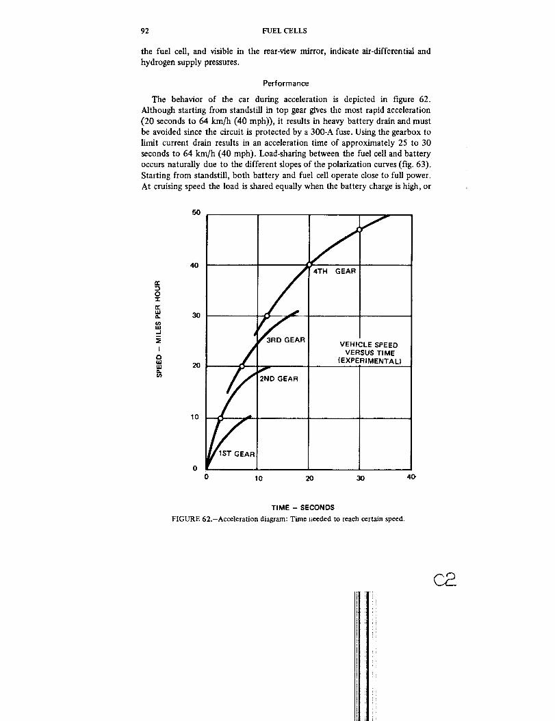
92 FUEL CELLS
the fuel cell, and visible in the rear-view mirror, indicate air-differential and
hydrogen supply pressures.
Performance
The behavior of the car during acceleration is depicted in figure 62.
Although starting from standstill in top gear gives the most rapid acceleration
(20 seconds to 64 km/h (40 mph)), it results in heavy battery drain and must
be avoided since the circuit is protected by a 300-A fuse. Using the gearbox to
limit current drain results in an acceleration time of approximately 25 to 30
seconds to 64 km/h (40 mph). Load-sharing between the fuel cell and battery
occurs naturally due to the different slopes of the polarization curves (fig. 63).
Starting from standstill, both battery and fuel cell operate close to full power.
At cruising speed the load is shared equally when the battery charge is high, or
erDo-r
tIJQ.
W..J
I
iiiILl
40
3O
10
f
SPEEDTIME
(EXPERIMENTAL)
0 10 2O 3O 40"
TIME - SECONDS
FIGURE 62.-Acceleration diagram: Time lleeded to reach certain speed.
C8

APPLICATIONS OF FUEL CELLS 93
130"
120
I10
I00
90
8O
7O
6O
5O
O3
0
PbO= DISCHARGE 8= CHARGE :
F • FULLY CHARGED
• }" _-" x I/4
"- 3/4
50 ASF IOOASF 150ASFI I I I t } t
0 50 I00 150 200
CURRENT AMPERES
FIGURE 63.-Load-sharing characteristics of fuel cell/battery system.
the power can be supplied solely from the fuel cell when the battery is almost
discharged. At standstill the fuel cell pumps energy into the battery at a rate
dependent on the state of charge. Experimental data on the load-sharing
characteristics are summarized in table 8.
The range of the car has been estimated from partial consumption figures as
320 km (200 mi). This is a significant improvement over battery-only vehicles,
which are usually limited to 80 to 160 km (50 to 100 mi). Dr. Kordesch's car,
for example, which was previously (1966) operated on lead batteries only, had
a range of 80 km (50 mi) in the summer and 48 km (30 mi) in the winter.
Operating costs are estimated at 0.5 cents per mile, based on a bulk purchase
price of 30 to 40 cents per pound (6.2 m 3 or 220 ft 3) of hydrogen. Based on
the delivered price of individual cylinders, it is estimated that the cost would
be as much as 5 cents per mile.
Maintenance
Routine maintenance procedures for the car include battery water replenish-
ment and periodic replacement of the sodalime CO2 scrubber. Water
replenishment must be done less frequently than originally anticipated,
probably because of good cooling of the batteries by air-flow due to their
placement and careful charge control using the ampere-hour counter as a
reference. The sodalime is changed twice in about 1 year of operation; and
apparently changes are not required more frequently than every 1600 km
(1000 mi). Special indicator particles included with the sodalime change color

94 FUELCELLS
TABLE8.-Load-Sharingof the Hydrogen-Air/Lead
System under Different Operating
Conditions (Experimental Data}
kW V A
11.0 85 125
9.5 80 115
8.0 75 105
6.5 70 95
20.0 75 260
14.0 65 210
12.0 60 195
8.0 90 90
7.0 85 80
5.6 80 70
4.5 72 60
4.0 70 58
3.0 84 352.0 88 22
0.5 II0 52.0 I00 20
2.8 95 30
4.2 85 50
Pb-battery H 2 -aiz Operatingstate-of-charge +A A conditions
1/1 - 80
3/4 - 60
1/2 - 40
1/4 - 25
III -200
3/4 - 140
1/2 -120
1/1 - 60
3/4 - 40
1/2 - 2O
1/4 0
1/4 + 7
1/2 + 8
1/2 + 13
I/I + 5
3/4 + 20
I/2 + 30I/4 + 50
Note: 60-A current equals 100 mA/cm 2
45 55 mph 4th gear
55 52 mph reduced field
65 48 mph battery temp.
70 42 mph 65 ° C
60 Steep hill, 2nd gear70 or start from stand.
75 Battery Temp. 45 ° C
30 45 mph 4th gear
40 42 mph full field50 38 mph battery temp.
60 35 mph 65 ° C
65 32 mph 4th gear
48 20 mph 3rd gear
35 10 mph 2nd gear
5 Car stopped.
20 Charging depends
30 on state of charge50 and temperature
cflrrent density.
when it is saturated, giving a clear visual indication of the need for
replacement. Periodic flushing of the fuel cells with water appears to be
desirable to remove buildup of dried electrolyte at the gas outlets. The
manifolds may be flushed with tap water without danger to the electrodes,
which are wetproofed.
The designer reports few problems with the system. The motor and its
control circuitry have operated without attention since their original installa-
tion in 1966. The batteries have a life expectancy of at least 2 years, and the
fuel cells have demonstrated lifetimes of 2000 hours continuous operation, the
equivalent of 80 000 to 96 000 km (50 000 to 60 000 mi), in laboratory tests.
Experience indicates that this expectancy may be increased under intermittent
use conditions.
The only serious problem reported is the development of leaks in the fuel
ceils, believed to be due to the use of mixture of materials with different
thermal expansion rates (nylon, plexiglass, and epoxy). This problem could be
solved by using one material throughout for construction, polysulfonates being
i

APPLICATIONS OF FUEL CELLS 95
recommended by the designer. The leaks have not proved catastrophic to either
the fuel cell or the environment. Potassium hydroxide does not damage the
vehicle body and may be washed off readily with water.
As installed, the fuel cell is quite accessible through the trunk opening of
the car (fig. 59) and from inside the car by tilting the rear seat. The underside
of the fuel cell may be reached for minor repairs by tilting the cell forward into
the body space after removing the seat back.
Future Fuel Cell-Powered Cars
The significant feature of Kordesch's car is its practicality. It represents a
low pollution vehicle with useful performance and range and a simplyoperated, fail-safe system. The technology embodied in the vehicle is quite old,
and the designer claims that recent improvements in electrode construction
would significantly improve the performance or could be used to extend the
range. The use of ammonia as fuel in conjunction with a thermal dissociationunit to convert it to hydrogen has been considered as a means of reducing the
fuel tankage volume.
The emphasis of current research in this field is on high-energy batteries
(zinc-air, sodium-sulfur, and others) and on low pollution internal combustion
engines, the fuel cell receiving little attention in comparison. The selection
between these approaches must be made on the basis of detailed technical and
economic analyses that are beyond the scope of this survey.


PRECEDING PAGE BLANK NOT FILMED
References
1. Grove, W. R.: On Voltaic Series in Combinations of Gases by Platinum. PhilosophicalMagazine, vol. 14, 1839, pp. 127-130.
2. Grove, W. R.: On A Small Voltaic Battery of Great Energy; Some Observations on
Voltaic Combinations and Forms of Arrangement; and on the Inactivity of a
Copper Positive Electrode in Nitro-Sulphuric Acid. Philosophical Magazine, vol. 15,
1839, pp. 287-293.
3. Grove, W. R.: On a Gaseous Voltaic Battery. Philosophical Magazine, vol. 21, 1842,
pp. 417-420.
4. Mond, L. L.; and Langer, C.: Proceedings of the Royal Society (London), Services, A,
vol. 46, 1890, pp. 296-304.
5. Grubb, W. T.: Ion-Exchange Batteries. Proceedings of the llth Annual Battery
Research and Development Conference, Atlantic City, N. J., 1957, pp. 5-8.
6. Austin, L. G.: Fuel Cells-A Review of Government-Sponsored Research, 1950-1964.
NASA SP-120, 1967.
7. Kordesch, K. V.: Low Temperature-Low-Pressure Fuel Cell with Carbon Electrodes.
Handbook of Fuel Cell Technology, edited by Carl Berger, Prentice-Hall, 1968.
8. Colman, W. P.; Gershberg, D.; Di Palma, J.; and Haldeman, R. G.: Light-Weight FuelCell Electrodes. Proceedings of the 19th Annual Power Sources Conferences, May
18-20, 1965.9. Grubb, W. T.; and Niedrach, L. W.: Batteries with Solid Ion-Exchange Membrane
Electrolytes, II. Low Temperature Hydrogen-Oxygen Fuel Cells. Journal of the
Electrochemical Society, vol. 107, Feb. 1960, pp. 131-135.
10. Liebhafsky, H. A.: Fuel Cells and Fuel Batteries-An Engineering View. IEEE
Spectrum, Dec. 1966, pp. 48-56.11. Rogers, L. J.: Hydrazine-Air (60/240 watt) Manpack Fuel Cell. Proceedings of the
23rd Annual Power Sources Conference, May 1969, pp. 1-4.
12. Warszawski, B.; Verger, B.; and Dumas, J. C.: Alsthom Fuel Cells for Marine and
Submarine Applications. Marine Technology Society Journal, vol. 5, no. 1,
Jam/Feb. 1971, pp. 28-41.
13. Adlhart, O. J.; and Terry, P. L.: Ammonia Fuel Cell System. Proceedings of the 4th
Intersociety Energy Conversion Engineering Conference, Sept. 1969, pp.1048-1051.
14. Rothschild: Fuel Cells. Science Journal, vol. 1, no. 1, Mar. 1965, pp. 82-87.
15. Ciprios, G.: The Methanol-Air Fuel Cell Battery. Proceedings of the 1st lntersocietyEnergy Conversion Engineering Conference, Sept. 1966, pp. 9-14.
16. PoLder, A. R.: Engineering Development of a Direct Hydrocarbon-Air Fuel Ceil
System. Proceedings of the 1st Intersociety Energy Conversion EngineeringConference, Sept. 1966.
17. Peattie, C. G.: Hydrocarbon-Air Fuel Cell Systems. IEEE Spectrum, June 1966, pp.69-76.
18. Frysinger, G. R.: Experience with Liquid Hydrocarbon Fuels. Proceedings of the 19th
Annual Power Sources Conference, May 1965, pp. 11-13.
97

98 FUEL CELLS
19. Juda, W.: A Hydrocarbon-Air Fuel Cell with Molten Alkali-Hydroxide Electrolyte.
Proceedings of the Electrochemical Society Meeting, Montreal, Oct. 1968.
20. Dunlop, J. D.; Van Ommering, G.; and Stockel, J. F.: Analysis of the Single-CeU
Concept for a Rechargeable H 2-O 2 Fuel Cell. Proceedings of the 6th lntersociety
Energy Conversion Engineering Conference, Aug. ! 971, pp. 906-917.
21. Giner, J., Holleck, G.; and Malachesky, P. A.: Research on Rechargeable Oxygen
Electrodes. NASA CR-72999, Jan. 1971.
22. Allison, A. J.; Ramakumar, R.; and Hughes, W. L.: Economic High-Pressure
Hydrogen-Oxygen Regenerative Fuel-Cell Systems. Proceedings of the 4th Inter-
society Energy Conversion Engineering Conference, Sept. 1969, pp. 1042-1047.
23. Durante, Lt. B.; Stedman, J. K.; and Bushnell, C. L.: High Power Density Fuel Cell.
Proceedings of the 4th lntersociety Energy Conversion Engineering Conference,
Washington, D. C., Sept. 1969.
24. Kordesch, K. V.: Hydrogen-Air/Lead Battery Hybrid System for Vehicle Propulsion.
Abstract No. 10, Electrochemical Society, Oct. 1970.
25. Malaspina, F. P.: 30-Watt Metal Hydride-Air Fuel Cell System. Proceedings of the
22nd Annual Power Sources Conference, May 1968, pp. 20-22.
26. Fee, G. G.; and Storto, E.: 20-Amp, 28 Vdc Hydrazine-Air Silent Power Source.
Proceedings of the 23rd Annual Power Systems Conference, May 1969, pp. 8-10.
27. Henry, J.; LeFort, R.; LeFeure, D.; and Verstraete, J.: Fuel Cell Economics and
Commercial Applications. Handbook of Fuel Cell Technology, edited by Carl
Berger, Prentice-Hall, 1968, pp. 496-596.
28. Harmison, L. T.; and Hastings, F. W.: Artificial Heart Program. Proceedings of the
Artificial Heart Program Conference, Washington, D.C., June 1969.
29. Beltzer, M.; and Batzold, J. S.: Linlitations of Blood Plasma as a Fuel Cell Electrolyte.
Proceedings of the 4th Intersociety Energy Conversion Engineering Conference,
Washington, D.C., Sept. 1969, pp. 354-360.
30. Messinger, S.; and Drake, R. F.: Trophically Powered Fuel Cell Power Supply for an
Artificial Heart. Proceedings of the 4th Intersociety Energy Conversion Engineering
Conference, Washington, D.C., Sept. 1969, pp. 361-369.
31. Appleby, A. J.; Ng. D. Y. C.; Wolfson, S. K.; and Weinstein, H.: An lmplantable
Biological Fuel Cell with an Air-Breathing Cathode_ Proceedings of the 4th
Intersociety Energy Conversion Engineering Conference, Washington, D.C., Sept.
1969, pp. 346-353.
32. Giner, J.; Holleck, G. L.; Turchan, M.; and Fragala, R.: An lmplantable Fuel Cell to
Power an Artificial Heart. Proceedings of the 6th lntersociety Energy Conversion
Engineering Conference, Boston, Mass., Aug. 1971, pp. 256-266.
33. Jaques, W. W.: Harpers Magazine, vol. 94, 1896, pp. 114-150.
34. Hart, A. B.; and Womack, G. J.: Fuel Cells. Chapman and Hall, 1967, pp. 274-292.
35. U.S. Department of Commerce: The Automobile and Air Pollution. Dec. 1967.
36. Heller, A. N.: An Examination of Alternatives to the Gasoline Automobile. Power
Systems for Electric Vehicles, pp. 5-12.
37. Frysinger, G. R.: Fuel CeU-Battery Power Sources for Electric Cars. Power Systems
for Electric Vehicles, U.S. Department of Health, Education and Welfare, Apr.
1967, pp. 83-90.
38. Hoffman, G. A.: The Electric Automobile. Scientific American, Oct. 1966, pp. 34-40.
39. Lindgren, N.: Electric Cars-Hope Springs Eternal. IEEE Spectrum, Apr. 1967, pp.
49-60.
40. Dantowitz, P.; and Caddy, L.: A State-of-the-Art Automotive Fuel Cell Power System
for Electric Vehicles, U. S. Department of Health, Education and Welfare, Apr.
1967, pp. 297-306.
41. Barak, M.: European Developments of Power Sources for Electric Vehicles. Power

REFERENCES 99
SystemsforElectricVehicles,U.S.DepartmentofHealth,EducationandWelfare,Apr.1967,pp.105-119.
42. Marks, C.; Rishavy, E. A.; and Wyczalek, F. A.: Electrovan-A Fuel Cell-Powered
Vehicle. Paper 670176, SAE Automotive Engineering Congress, Detroit, Jan. 1967.
43. Winters, C. E.; and Morgan, W. L.: The Hydrogen-Oxygen Thin Electrode Fuel Cell
Module. Paper 670182, SAE Automotive Engineering Congress, Detroit.
44. Wyczalek, F. A.; Frank, D. L.; and Smith, G. E.: A Vehicle Fuel Cell System. Paper
670181, SAE Automotive Engineering Congress, Detroit.
45. Kordesch, K. V.: City Car with H2-Air Fuel Cell/Lead Battery (One Year Operating
Experiences). Proceedings of the 1971 Intersociety Energy Conversion Engineering
Conference, Boston, Mass., Aug. 1971, pp. 103-111.
Q


PRECEDING PAGE BLANK NOT FILMED
Bibliography
Adl_hatt, O. J.; and Terry, P. L.: Ammonia Fuel Cell System. Proceedings of the 4th
Intersociety Energy Conversion Engineering Conference, Sept. 1969, pp. 1048-1051.
Allison, A. J.; Ramakumar, R.; and Hughes, W. L.: Economic High-Pressure Hydrogen-
Oxygen Regenerative Fuel-Cell Systems. Proceedings of the 4th Intersociety Energy
Conversion Engineering Conference, Sept. 1969, pp. 1042-1047.
Appleby, A. J.; Ng, D. Y. C.; Wolfson, S. K.; and Weinstein, H.: An lmplantable Biological
Fuel Cell with an Air-Breathing Cathode. Proceedings of the 4th Intersociety Energy
Conversion Engineering Conference, Washington, D.C., Sept. 1969, pp. 346-353.
Archer, D. H,: Fuel Cells for Central Power Generation. ASME Paper No. 67-PWR-10,
ASME-IEEE Joint Power Generation Conference, Detroit, Sept. 1967.
Austin, L. G.: Electrode Kinetics and Fuel Cells. Proceedings of the IEEE, voi. 51,
Jan.June 1963, pp. 820-837.
Austin, L. G.: Fuel Cells-A Review of Government-Sponsored Research, 1950-1964.
NASA SP-120, 1967.
Barak, M.: European Developments of Power Sources for Electric Vehicles. Power Systems
for Electric Vehicles, U.S. Department of Health, Education and Welfare, Apr. 1967,
pp. 105-119.
Beitzer, M.; and Batzoid, J. S.: Limitations of Blood Plasma as a Fuel Cell Electrolyte.
Proceedings of the 4th Intersociety Energy Conversion Engineering Conference,
Washington, D.C., Sept. 1969, pp. 354-160.
Bender, R. J.: The Fuel Cell: Commercial in the 7O's? Power, Apr. 1971, pp. 60-61.
Bockris, J. O'M.; and Wroblowa, H.: Electrochemical Catalysis. AGARD-NATO Com-
bustion and Propulsion: Colloquium on Energy Sources and Energy Conversion,
Agardographs Series, no. 81, 1967, pp. 717-767.
Cipnos, G.: The Methanol-Air Fuel Cell Battery. Proceedings of the 1st Intersociety
Energy Conversion Engineering Conference, Sept. 1966, pp. 9-14.
Cohn, E. M.: Electrochemical Space Power Sources. AGARD Space Power Systems, Part
2, 1969, pp. 443-501.
Colman, W. P.; Gershberg, D.; Di Palma, J.; and Haldeman, R. G.: Light-Weight.Fuel Cell
Electrodes. Proceedings of the 19th Annual Power Sources Conferences, May 18-20,
1965.
Dantowitz, P.; and Caddy, L.: A State-of-the-Art Automotive Fuel Cell Power System for
Electric Vehicles. U. S. Department of Health, Education and Welfare, Apr. 1967, pp.
297-306.
Dunlop, J. D.; Van Ommering, G.; and Stockel, J. F.: Analysis of the Single-Cell Concept
for a Rechaxgeable H2-O 2 Fuel Cell. Proceedings of the 6th Intersociety Energy
Conversion Engineering Conference, Aug. 1971, pp. 906-917.
Durante, Lt. B.; Stedman, J. K.; and Bushnell, C. L.: High Power Density Fuel Cell.
Proceedings of the 4th Intersociety Energy Conversion Engineering Conference,
Washington, D. C., Sept. 1969.
Fee, G. G.; and Storto, E.: 20-Amp. 28 Vdc Hydrazine-Air Silent Power Source.
Proceedings of the 23rd Annual Power Systems Conference, May 1969, pp. 8-10.
101

102 FUEL CELLS
Frysinger, G. R.: Experience with Liquid Hydrocarbon Fuels. Proceedings of the 19th
Annual Power Sources Conference, May 1965, pp. 11-13.
Frysinger, G. R.: Fuel Cell-Battery Power Sources for Electric Cars. Power Systems for
Electric Vehicles, U. S. Department of Health, Education and Welfare, Apr. 1967, pp.
83-90.
Frysinger, G. R.: The Economical Fuel Cell. IEEE Spectrum, Mar. 1969, pp. 83-90.
Giacolet]o, L. J.: Energy Storage and Conversion. IEEE Spectrum, Feb. 1965, pp. 95-102.
Gidaspow, D.; Baker, B. S.; and Schmidt, T.: Thermal Design of Molten Carbonate Fuel
Ceils. Proceedings of the 1st Intersociety Energy Conversion Engineering Conference,
Sept. 1966, pp. 19-23.
Giner, J.; Holleck, G.; and Malachesky, P. A.: Research on Rechargeable Oxygen
Electrodes. NASA CR-72999, Jan. 1971.
Giner, J.; Holleck, G.; Turchan, M.; and Fragala, R.: An Implantable Fuel Cell to Power an
Artificial Heart. Proceedings of the 6th Intersociety Energy Conversion Engineering
Conference, Boston, Mass., Aug. 1971, pp. 256-266.
Grove, W. R.: On A Gaseous Voltaic Battery. Philosophical Magazine, vol. 21, 1842, pp.
417-420.
Grove, W. R.: On A Small Voltaic Battery of Great Energy; Some Observations on Voltaic
Combinations and Forms of Arrangement; and on the Inactivity of a Copper Positive
Electrode in Nit_o-Sulphuric Acid. Philosophical Magazine, vol. 15, 1839, pp. 287-293.
Grove, W. R.: On Voltaic Series in Combinations of Gases by Platinum. Philosophical
Magazine, vol. 14, 1839, pp. 127-130.
Grubb, W. T.: Ion-Exchange Batteries. Proceedings of the 11 th Annual Battery Research
and Development Conference, Atlantic City, N. J., 1957, pp. 5-8.
Grubb, W. T.; and Niedrach, L. W.: Batteries with Solid Ion-Exchange Membrane
Electrolytes, II. Low Temperature Hydrogen-Oxygen Fuel Cells, Journal of the
Electrochemical Society, vol. 107, Feb. 1960, pp. 131-135.
Harmison, L. T.; and Hastings, F. W.: Artificial Heart Program. Proceedings of the
Artificial Heart Program Conference, Washington, D. C., June 1969.
Hart, A. B.; and Womack, G. J.: Fuel Cells. Chapman and Hall, 1967, pp. 274-292.
Heller, A. N.: An Examination of Alternatives to the Gasoline Automobile. Power Systems
for Electric Vehicles, pp. 5-12.
Henry, J.; LeFort, R.; LeFeure, D.; and Verstraete, J.: Fuel Cell Economics and
Commercial Applications. Handbook of Fuel Cell Technology, edited by Carl Berger,
Prentice-Hall, 1968, pp. 496-596.
Hoffman, G. A.: Energy Requirements for Electric Automobiles. Proceedings of the 1st
Intersociety Energy Conversion Engineering Conference, Los Angeles, Sept. 1966, pp.
368-379.
Hoffman, G. A.: The Electric Automobile. Scientific American, Oct. 1966, pp. 34-40.
Jaques, W. W.: Harpers Magazine, vol. 94, 1896, pp. 114-150.
Juda, W.: A Hydrocarbon-Air Fuel Cell with Molten Alkali-Hydroxide Electrolyte.
Proceedings of the Electrochemical Society Meeting, Montreal, Oct. 1968.
Justi, E. W.: Fuel Cell Research in Europe. Proceedings of the IEEE, vol. 51, Jan.-June
1963, pp. 784-795.
Kordesch, K. V.: City Car with He-Air Fuel Cell/Lead Battery (One Year Operating
Experiences). Proceedings of the 1971 Intersociety Energy Conversion Engineering
Conference, Boston, Mass., Aug. 1971, pp. 103-111.
Kordesch, K. V.: Hydrogen-Air/Lead Battery Hybrid System for Vehicle Propulsion.
Abstract No. 10, Electrochemical Society Meeting, Oct. 1970.
Kordesch, K. V.: Low Temperature Fuel Cells. Proceedings of the IEEE, vol. 51, Jan:June
1963, pp. 806-8t2.
Kordesch, K. V.: Low Temperature-Low-Pressure Fuel Cell with Carbon Electrodes.
Handbook of Fuel CellTechnology; edited by Carl Berger, Prentice-Hall, 1968.

BIBLIOGRAPHY 103
Liebhafsky, H. A.: Fuel Cells and Fuel Batteries-An Engineering View. IEEE Spectrum,
Dec. 1966, pp. 48-56.
Lindgren, N.: Electric Cars-Hope Springs Eternal. IEEE Spectrum, Apr. 1967, pp. 49-60.
Malaspina, F. P.: 30-Watt Metal Hydride-Air Fuel Cell System. Proceedings of the 22nd
Annual Power Sources Conference, May 1968, pp. 20-22.
Marks, C.; Rishavy, E. A.; and Wyczalek, F. A.: Electrovan - A Fuel Cell-Powered
Vehicle. Paper 670176, SAE Automotive Engineering Congress, Detroit, Jan. 1967.
Messinger, S.; and Drake, R. F.: Trophically Powered Fuel Cell Power Supply for an
Artificial Heart. Proceedings of the 4th lntersociety Energy Conversion Engineering
Conference, Washington, D. C., Sept. 1969, pp. 361-369.
Mond, L. L.; and Langei, C.: Proceedings of the Royal Society (London), Services, A, vol.
46, 1890, pp. 296-304.
Peattie, C. G.: A Summary of Practical Fuel Cell Technology to 1963. Proceedings of the
IEEE, vol. 51, Jan.-June 1963, pp. 795-806.
Peattie, C. G.: Hydrocarbon-Air Fuel Cell Systems. IEEE Spectrum, June 1966, pp. 69-76.
Poirier, A. R.: Engineering Development of a Direct Hydrocarbon-Air Fuel Cell System.
Proceedings of the 1st lntersociety Energy Conversion Engineering Conference, Sept.
1966.
Reid, W. T.: Energy Sources for Electrically Powered Automobiles. Battelle Technical
Review, no. 14, pp. 9-15.
Ritchings, F. A.: Raw Energy Sources for Electric Generation. IEEE Spectrum, Aug.
1968, pp. 34-45. G
Rogers, L. J.: Hydrazine-Air (60/240 watt) Manpack Fuel Cell. Proceedings of the 23rd
Annual Power Sources Conference, May 1969, pp. 1-4.
Rothschild: Fuel Cells. Science Journal, vol. 1, no. 1, Mar. 1965, pp. 82-87.
Smith, A. B.: Fuel Cells-Power for Tomorrow. Radio Electronics, Feb. 1967, pp. 44-47.
Spadone, D. M.: Power for Deep-Submergence Vehicles. Astronautics and Aeronautics,
July 1967, pp. 76-79.
Spring, K. H., ed.: Direct Generation of Electricity. Academic Press, 1965.
U. S. Department of Commerce: The Automobile and Air Pollution, Dec. 1967.
Vogely, W. A.: Analytical Uses of Energy Balances. IEEE Spectrum, May 1969, pp. 57-63.
Warszawski, B.; Verger, B; and Dumas, J. C.: Alsthom Fuel Ceils for Marine and
Submarine Applications. Marine Technology Society Journal, vol. 5, no. 1, Jan./Feb.
1971, pp. 28-41.
Watson, R. G. H.: Fuel Cell Reactant Properties. AGARD-NATO Combustion and
Propulsion: Colloquium on Energy Sources and Energy Conversion, Agardograph
Series, no. 81, 1967, pp. 681-707.
Winters, C. E.; and Morgan, W. L.: The Hydrogen-Oxygen Thin Electrode Fuel Cell
Module. Paper 670182, SAE Automotive Engineering Congress, Detroit.
Wyczalek, F. A.; Frank, D. L.; and Smith, G. E.: A Vehicle Fuel Cell System. Paper
670181, SAE Automotive Engineering Congress, Detroit.
Yeager, E.; and Kozawa, A.: Kinetic Factors in Fuel Cell Systems: The Oxygen Electrode.
AGARD-NATO Combustion and Propulsion: Colloquium on Energy Sources and
Energy Conversion, Agardograph Series, no. 81, 1967, pp. 769-793.


PRECEDLNG PAGE BLANK NOT FILMED
APPENDIX A
Sources of Further Information
Readers wishing to explore the technology of fuel cells more thoroughly
may find the following list of information sources a useful supplement to the
bibliography.
BOOKS
The following books were published during the period 1961 to 1971.
Because of the rapid advances made in the technology then, the most recently
published books are listed first.
Baker, B. S.; and Gould, R. F.: Fuel Cell Systems - 2. (Advances in Chemistry Series No.
90), American Chemical Society, 1969.
Bockris, J. O'M.; and Srinivasan, T.: Fuel Cells: Their Electrochemistry. McGraw-Hill, 1969.
Breiter, M. W.. Electrochemical Processes in Fuel Cells. Springer-Verlag, 1969.
Ranney, M.: Fuel Cells. Noyes, 1969.
Berger, C.: Handbook of Fuel Cell Technology. Prentice-Hall, 1968.Liebhafsky, H. A.; and Cairns, E. J.: Fuel Cells and Fuel Batteries: A Guide to Their
Research and Development. Wiley, 1968.
Austin, L. G.: Fuel CeUs-A Review of Government-Sponsored Research, 1950-1964.NASA (SP-120), 1967.
Hart, A. B.; and Womack, G. J.: Fuel Cells: Theory and Application. Chapman and Hall,1967.
Bagotsky, V. S.; and VasirEv, Y. B.: Fuel Cells: Their Electrochemical Kinetics. PlenumPub., 1966.
Baker, B. S.: Hydrocarbon Fuel Cell Technology: A Symposium. Academic Press, 1966.
Halacy, D. S., Jr.: Fuel Cells: Power for Tomorrow. World Pub.i 1966.Klein, H. A.: Fuel Cells, Lippincott, 1966.
Williams, K. R.: Introduction to Fuel Cells. Elsevier, Amsterdam, 1966.
American Chemical Society. Fuel Cell Systems. Advances in Chemistry Series No. 47,
American Chemical Society Pub., 1965.
Mitchell, W., Jr.: Fuel Cells. (Chemical Technology, Vol. 1), Academic Press, 1963.
American Chemical Society. Fuel Cells. Vol. 2, Young, G. J., Ed., Reinhold, 1962.
Justi, E. W.; and Winsel, A. W.: Cold Combustion Fuel Cells. Franz Steiner, Wiesbaden,Germany, 1962.
PERIODICALS
No periodical currently published is devoted specifically to fuel cells.
However, several regularly scheduled conferences and meetings deal with fuel
cell technology, and the proceedings form a valuable source of information on
current developments.
105

106 FUEL CELLS
Power Sources
A Power Sources Symposium (PSS) is held annually to present and discuss
results of Government, university, and industrial investigations in the powerfield. The conference is sponsored by the Power Sources Division, Electronic
Components Laboratory, U.S. Army Electronics Command, Fort Monmouth,
N.J. The proceedings of the Conference are published and distributed by the
PSS Publications Committee, P. O. Box 891, Red Bank, N.J. 07701.
In tersociety Energy Conversion Engineering Conference (IECEC)
The IECEC meets in August or September each year to present the results
of the engineering and application aspects of nonconventional energy con-
version. It is cosponsored by the seven member societies listed below. Each
society in turn has published the proceedings, in the order listed.American Society of Mechanical Engineers (ASME), 1967
Institute of Electrical and Electronics Engineers (IEEE), 1968American Institute of Chemical Engineers (AIChE), 1969
American Nuclear Society (ANS), 1970
Society of Automotive Engineers (SAE), 1971
American Chemical Society (ACS)The 1972 conference will be hosted by the ACS in San Diego, September
25-29. The conference chairman is Mr. A. T. Winstead of ACS. The AIAA will
be host to the 1973 conference.
Electrochemical Society Meetings
The Electrochemical Society (ECS) meets in the spring and fall each year.
Papers presented include those on fuel cell technology and applications. For
information contact: The Electrochemical Society, 30 East 42nd Street, New
York, New York.
International Power Sources Symposium (IPSS)
The IPSS (until 1964, the International Symposium on Batteries) is held
once every 2 years at Brighton, England. The Symposia are sponsored by the
British Joint Services Electrical Power Sources Committee and the proceedings
are edited by D. H. Collins and published by Pergamon Press.
Annual Cl TCE Meetings
The International Committee of Electr6chemical Thermodynamics and
Kinetics (Comit_ International de Thermodynamique et de Cinetique Electro-
chimique, CITCE) meets annually. Papers presented at the conference are
published in the committee's journal, Electrochimica Acta, by Pergamon Press.
U.S. GOVERNMENT PRINTING OFFICE : 1973 O-499-155
]
'I
i
Related Documents