Northumbria Research Link Citation: Wells, Gary, Ledesma-Aguilar, Rodrigo, McHale, Glen and Sefiane, Khellil (2015) A sublimation heat engine. Nature Communications, 6. p. 6390. ISSN 2041-1723 Published by: Nature Publishing URL: https://doi.org/10.1038/ncomms7390 <https://doi.org/10.1038/ncomms7390> This version was downloaded from Northumbria Research Link: http://nrl.northumbria.ac.uk/id/eprint/21600/ Northumbria University has developed Northumbria Research Link (NRL) to enable users to access the University’s research output. Copyright © and moral rights for items on NRL are retained by the individual author(s) and/or other copyright owners. Single copies of full items can be reproduced, displayed or performed, and given to third parties in any format or medium for personal research or study, educational, or not-for-profit purposes without prior permission or charge, provided the authors, title and full bibliographic details are given, as well as a hyperlink and/or URL to the original metadata page. The content must not be changed in any way. Full items must not be sold commercially in any format or medium without formal permission of the copyright holder. The full policy is available online: http://nrl.northumbria.ac.uk/policies.html This document may differ from the final, published version of the research and has been made available online in accordance with publisher policies. To read and/or cite from the published version of the research, please visit the publisher’s website (a subscription may be required.)

Welcome message from author
This document is posted to help you gain knowledge. Please leave a comment to let me know what you think about it! Share it to your friends and learn new things together.
Transcript

Northumbria Research Link
Citation: Wells, Gary, Ledesma-Aguilar, Rodrigo, McHale, Glen and Sefiane, Khellil (2015)A sublimation heat engine. Nature Communications, 6. p. 6390. ISSN 2041-1723
Published by: Nature Publishing
URL: https://doi.org/10.1038/ncomms7390 <https://doi.org/10.1038/ncomms7390>
This version was downloaded from Northumbria Research Link:http://nrl.northumbria.ac.uk/id/eprint/21600/
Northumbria University has developed Northumbria Research Link (NRL) to enable usersto access the University’s research output. Copyright © and moral rights for items onNRL are retained by the individual author(s) and/or other copyright owners. Single copiesof full items can be reproduced, displayed or performed, and given to third parties in anyformat or medium for personal research or study, educational, or not-for-profit purposeswithout prior permission or charge, provided the authors, title and full bibliographicdetails are given, as well as a hyperlink and/or URL to the original metadata page. Thecontent must not be changed in any way. Full items must not be sold commercially in anyformat or medium without formal permission of the copyright holder. The full policy isavailable online: http://nrl.northumbria.ac.uk/policies.html
This document may differ from the final, published version of the research and has beenmade available online in accordance with publisher policies. To read and/or cite from thepublished version of the research, please visit the publisher’s website (a subscriptionmay be required.)
ARTICLE
Received 17 Jul 2014 | Accepted 27 Jan 2015 | Published 3 Mar 2015
A sublimation heat engineGary G. Wells1, Rodrigo Ledesma-Aguilar1, Glen McHale1 & Khellil Sefiane2,3
Heat engines are based on the physical realization of a thermodynamic cycle, most famously
the liquid–vapour Rankine cycle used for steam engines. Here we present a sublimation heat
engine, which can convert temperature differences into mechanical work via the Leidenfrost
effect. Through controlled experiments, quantified by a hydrodynamic model, we show that
levitating dry-ice blocks rotate on hot turbine-like surfaces at a rate controlled by the turbine
geometry, temperature difference and solid material properties. The rotational motion of the
dry-ice loads is converted into electric power by coupling to a magnetic coil system.
We extend our concept to liquid loads, generalizing the realization of the new engine to both
sublimation and the instantaneous vapourization of liquids. Our results support the feasibility
of low-friction in situ energy harvesting from both liquids and ices. Our concept is potentially
relevant in challenging situations such as deep drilling, outer space exploration or
micro-mechanical manipulation.
DOI: 10.1038/ncomms7390 OPEN
1 Department of Physics and Electrical Engineering, Northumbria University, Ellison Place, Newcastle upon Tyne NE1 8ST, UK. 2 School of Engineering,University of Edinburgh, The King’s Buildings, Mayfield Road, Scotland EH9 3FB, UK. 3 International Institute for Carbon-Neutral Energy Research (I2CNER)and Department of Mechanical Engineering, Kyushu University, 744 Motooka, Nishi-ku Fukuoka, Fukuoka 819-0395, Japan. Correspondence and requests formaterials should be addressed to R.L.-A. (email: [email protected]).
NATURE COMMUNICATIONS | 6:6390 | DOI: 10.1038/ncomms7390 | www.nature.com/naturecommunications 1
& 2015 Macmillan Publishers Limited. All rights reserved.
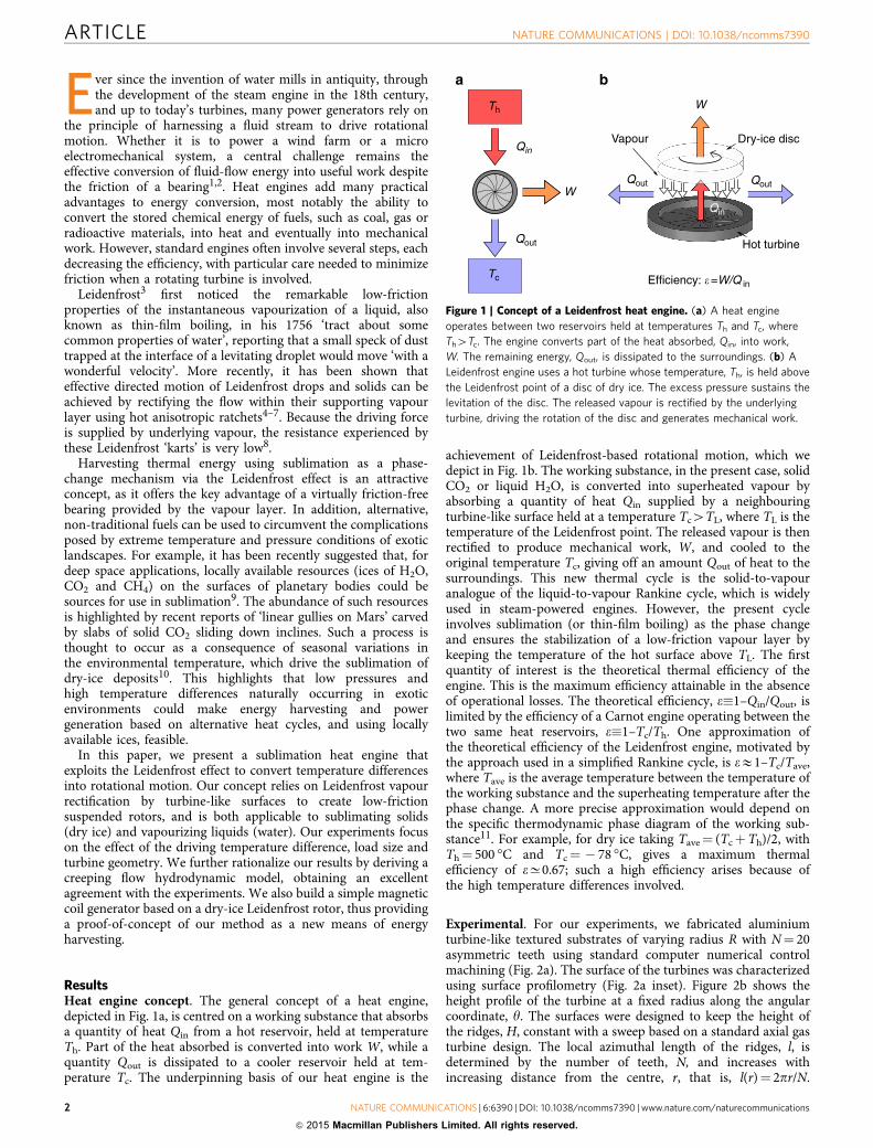
Ever since the invention of water mills in antiquity, throughthe development of the steam engine in the 18th century,and up to today’s turbines, many power generators rely on
the principle of harnessing a fluid stream to drive rotationalmotion. Whether it is to power a wind farm or a microelectromechanical system, a central challenge remains theeffective conversion of fluid-flow energy into useful work despitethe friction of a bearing1,2. Heat engines add many practicaladvantages to energy conversion, most notably the ability toconvert the stored chemical energy of fuels, such as coal, gas orradioactive materials, into heat and eventually into mechanicalwork. However, standard engines often involve several steps, eachdecreasing the efficiency, with particular care needed to minimizefriction when a rotating turbine is involved.
Leidenfrost3 first noticed the remarkable low-frictionproperties of the instantaneous vapourization of a liquid, alsoknown as thin-film boiling, in his 1756 ‘tract about somecommon properties of water’, reporting that a small speck of dusttrapped at the interface of a levitating droplet would move ‘with awonderful velocity’. More recently, it has been shown thateffective directed motion of Leidenfrost drops and solids can beachieved by rectifying the flow within their supporting vapourlayer using hot anisotropic ratchets4–7. Because the driving forceis supplied by underlying vapour, the resistance experienced bythese Leidenfrost ‘karts’ is very low8.
Harvesting thermal energy using sublimation as a phase-change mechanism via the Leidenfrost effect is an attractiveconcept, as it offers the key advantage of a virtually friction-freebearing provided by the vapour layer. In addition, alternative,non-traditional fuels can be used to circumvent the complicationsposed by extreme temperature and pressure conditions of exoticlandscapes. For example, it has been recently suggested that, fordeep space applications, locally available resources (ices of H2O,CO2 and CH4) on the surfaces of planetary bodies could besources for use in sublimation9. The abundance of such resourcesis highlighted by recent reports of ‘linear gullies on Mars’ carvedby slabs of solid CO2 sliding down inclines. Such a process isthought to occur as a consequence of seasonal variations inthe environmental temperature, which drive the sublimation ofdry-ice deposits10. This highlights that low pressures andhigh temperature differences naturally occurring in exoticenvironments could make energy harvesting and powergeneration based on alternative heat cycles, and using locallyavailable ices, feasible.
In this paper, we present a sublimation heat engine thatexploits the Leidenfrost effect to convert temperature differencesinto rotational motion. Our concept relies on Leidenfrost vapourrectification by turbine-like surfaces to create low-frictionsuspended rotors, and is both applicable to sublimating solids(dry ice) and vapourizing liquids (water). Our experiments focuson the effect of the driving temperature difference, load size andturbine geometry. We further rationalize our results by deriving acreeping flow hydrodynamic model, obtaining an excellentagreement with the experiments. We also build a simple magneticcoil generator based on a dry-ice Leidenfrost rotor, thus providinga proof-of-concept of our method as a new means of energyharvesting.
ResultsHeat engine concept. The general concept of a heat engine,depicted in Fig. 1a, is centred on a working substance that absorbsa quantity of heat Qin from a hot reservoir, held at temperatureTh. Part of the heat absorbed is converted into work W, while aquantity Qout is dissipated to a cooler reservoir held at tem-perature Tc. The underpinning basis of our heat engine is the
achievement of Leidenfrost-based rotational motion, which wedepict in Fig. 1b. The working substance, in the present case, solidCO2 or liquid H2O, is converted into superheated vapour byabsorbing a quantity of heat Qin supplied by a neighbouringturbine-like surface held at a temperature Tc4TL, where TL is thetemperature of the Leidenfrost point. The released vapour is thenrectified to produce mechanical work, W, and cooled to theoriginal temperature Tc, giving off an amount Qout of heat to thesurroundings. This new thermal cycle is the solid-to-vapouranalogue of the liquid-to-vapour Rankine cycle, which is widelyused in steam-powered engines. However, the present cycleinvolves sublimation (or thin-film boiling) as the phase changeand ensures the stabilization of a low-friction vapour layer bykeeping the temperature of the hot surface above TL. The firstquantity of interest is the theoretical thermal efficiency of theengine. This is the maximum efficiency attainable in the absenceof operational losses. The theoretical efficiency, e�1–Qin/Qout, islimited by the efficiency of a Carnot engine operating between thetwo same heat reservoirs, e�1–Tc/Th. One approximation ofthe theoretical efficiency of the Leidenfrost engine, motivated bythe approach used in a simplified Rankine cycle, is eE1–Tc/Tave,where Tave is the average temperature between the temperature ofthe working substance and the superheating temperature after thephase change. A more precise approximation would depend onthe specific thermodynamic phase diagram of the working sub-stance11. For example, for dry ice taking Tave¼ (TcþTh)/2, withTh¼ 500 �C and Tc¼ � 78 �C, gives a maximum thermalefficiency of eC0.67; such a high efficiency arises because ofthe high temperature differences involved.
Experimental. For our experiments, we fabricated aluminiumturbine-like textured substrates of varying radius R with N¼ 20asymmetric teeth using standard computer numerical controlmachining (Fig. 2a). The surface of the turbines was characterizedusing surface profilometry (Fig. 2a inset). Figure 2b shows theheight profile of the turbine at a fixed radius along the angularcoordinate, y. The surfaces were designed to keep the height ofthe ridges, H, constant with a sweep based on a standard axial gasturbine design. The local azimuthal length of the ridges, l, isdetermined by the number of teeth, N, and increases withincreasing distance from the centre, r, that is, l(r)¼ 2pr/N.
Th
Qin
Qout
Qout Qout
Qin
Tc
W
Vapour
W
Hot turbine
Dry-ice disc
Efficiency: �=W/Q in
Figure 1 | Concept of a Leidenfrost heat engine. (a) A heat engine
operates between two reservoirs held at temperatures Th and Tc, where
Th4Tc. The engine converts part of the heat absorbed, Qin, into work,
W. The remaining energy, Qout, is dissipated to the surroundings. (b) A
Leidenfrost engine uses a hot turbine whose temperature, Th, is held above
the Leidenfrost point of a disc of dry ice. The excess pressure sustains the
levitation of the disc. The released vapour is rectified by the underlying
turbine, driving the rotation of the disc and generates mechanical work.
ARTICLE NATURE COMMUNICATIONS | DOI: 10.1038/ncomms7390
2 NATURE COMMUNICATIONS | 6:6390 | DOI: 10.1038/ncomms7390 | www.nature.com/naturecommunications
& 2015 Macmillan Publishers Limited. All rights reserved.
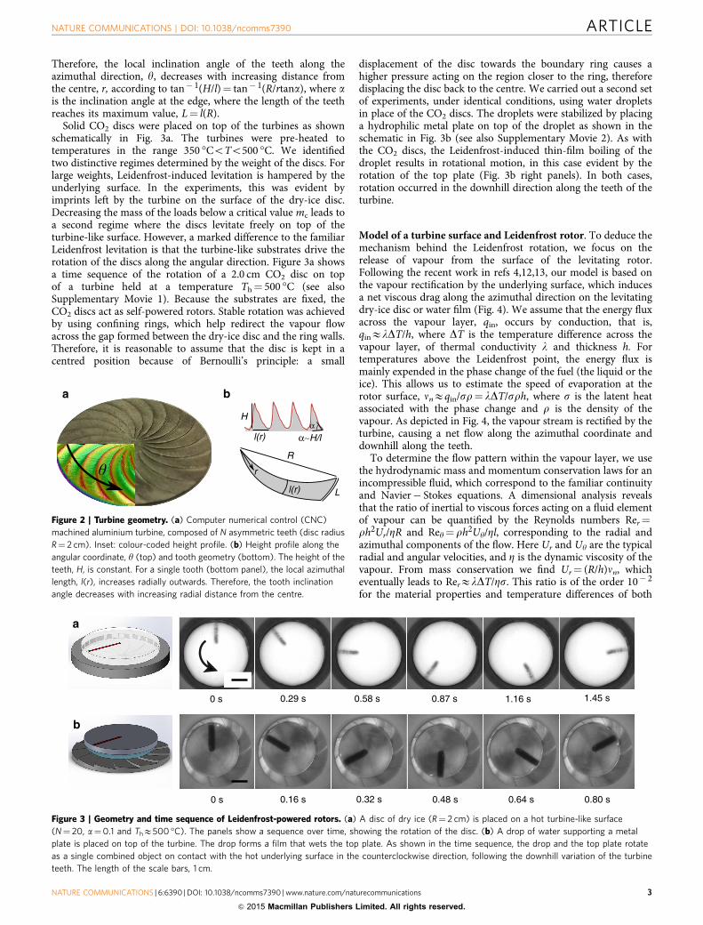
Therefore, the local inclination angle of the teeth along theazimuthal direction, y, decreases with increasing distance fromthe centre, r, according to tan� 1(H/l)¼ tan� 1(R/rtana), where ais the inclination angle at the edge, where the length of the teethreaches its maximum value, L¼ l(R).
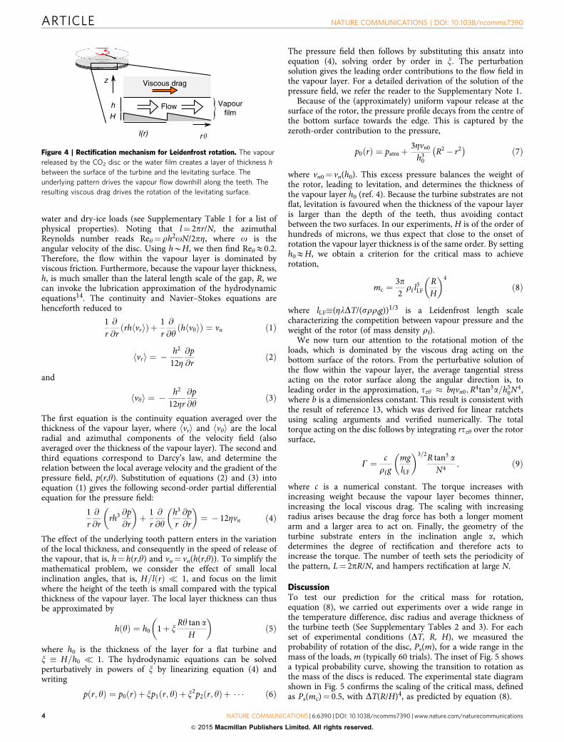
Solid CO2 discs were placed on top of the turbines as shownschematically in Fig. 3a. The turbines were pre-heated totemperatures in the range 350 �CoTo500 �C. We identifiedtwo distinctive regimes determined by the weight of the discs. Forlarge weights, Leidenfrost-induced levitation is hampered by theunderlying surface. In the experiments, this was evident byimprints left by the turbine on the surface of the dry-ice disc.Decreasing the mass of the loads below a critical value mc leads toa second regime where the discs levitate freely on top of theturbine-like surface. However, a marked difference to the familiarLeidenfrost levitation is that the turbine-like substrates drive therotation of the discs along the angular direction. Figure 3a showsa time sequence of the rotation of a 2.0 cm CO2 disc on topof a turbine held at a temperature Th¼ 500 �C (see alsoSupplementary Movie 1). Because the substrates are fixed, theCO2 discs act as self-powered rotors. Stable rotation was achievedby using confining rings, which help redirect the vapour flowacross the gap formed between the dry-ice disc and the ring walls.Therefore, it is reasonable to assume that the disc is kept in acentred position because of Bernoulli’s principle: a small
displacement of the disc towards the boundary ring causes ahigher pressure acting on the region closer to the ring, thereforedisplacing the disc back to the centre. We carried out a second setof experiments, under identical conditions, using water dropletsin place of the CO2 discs. The droplets were stabilized by placinga hydrophilic metal plate on top of the droplet as shown in theschematic in Fig. 3b (see also Supplementary Movie 2). As withthe CO2 discs, the Leidenfrost-induced thin-film boiling of thedroplet results in rotational motion, in this case evident by therotation of the top plate (Fig. 3b right panels). In both cases,rotation occurred in the downhill direction along the teeth of theturbine.
Model of a turbine surface and Leidenfrost rotor. To deduce themechanism behind the Leidenfrost rotation, we focus on therelease of vapour from the surface of the levitating rotor.Following the recent work in refs 4,12,13, our model is based onthe vapour rectification by the underlying surface, which inducesa net viscous drag along the azimuthal direction on the levitatingdry-ice disc or water film (Fig. 4). We assume that the energy fluxacross the vapour layer, qin, occurs by conduction, that is,qinElDT/h, where DT is the temperature difference across thevapour layer, of thermal conductivity l and thickness h. Fortemperatures above the Leidenfrost point, the energy flux ismainly expended in the phase change of the fuel (the liquid or theice). This allows us to estimate the speed of evaporation at therotor surface, nnEqin/sr¼ lDT/srh, where s is the latent heatassociated with the phase change and r is the density of thevapour. As depicted in Fig. 4, the vapour stream is rectified by theturbine, causing a net flow along the azimuthal coordinate anddownhill along the teeth.
To determine the flow pattern within the vapour layer, we usethe hydrodynamic mass and momentum conservation laws for anincompressible fluid, which correspond to the familiar continuityand Navier� Stokes equations. A dimensional analysis revealsthat the ratio of inertial to viscous forces acting on a fluid elementof vapour can be quantified by the Reynolds numbers Rer¼rh2Ur/ZR and Rey¼ rh2Uy/Zl, corresponding to the radial andazimuthal components of the flow. Here Ur and Uy are the typicalradial and angular velocities, and Z is the dynamic viscosity of thevapour. From mass conservation we find Ur¼ (R/h)nn, whicheventually leads to RerElDT/Zs. This ratio is of the order 10� 2
for the material properties and temperature differences of both
αH
L
R
l(r)
l(r)
r
α∼H/l
Figure 2 | Turbine geometry. (a) Computer numerical control (CNC)
machined aluminium turbine, composed of N asymmetric teeth (disc radius
R¼ 2 cm). Inset: colour-coded height profile. (b) Height profile along the
angular coordinate, y (top) and tooth geometry (bottom). The height of the
teeth, H, is constant. For a single tooth (bottom panel), the local azimuthal
length, l(r), increases radially outwards. Therefore, the tooth inclination
angle decreases with increasing radial distance from the centre.
a
b
0 s
0 s
0.29 s
0.16 s 0.32 s 0.48 s 0.64 s 0.80 s
0.58 s 0.87 s 1.16 s 1.45 s
Figure 3 | Geometry and time sequence of Leidenfrost-powered rotors. (a) A disc of dry ice (R¼ 2 cm) is placed on a hot turbine-like surface
(N¼ 20, a¼0.1 and ThE500 �C). The panels show a sequence over time, showing the rotation of the disc. (b) A drop of water supporting a metal
plate is placed on top of the turbine. The drop forms a film that wets the top plate. As shown in the time sequence, the drop and the top plate rotate
as a single combined object on contact with the hot underlying surface in the counterclockwise direction, following the downhill variation of the turbine
teeth. The length of the scale bars, 1 cm.
NATURE COMMUNICATIONS | DOI: 10.1038/ncomms7390 ARTICLE
NATURE COMMUNICATIONS | 6:6390 | DOI: 10.1038/ncomms7390 | www.nature.com/naturecommunications 3
& 2015 Macmillan Publishers Limited. All rights reserved.
water and dry-ice loads (see Supplementary Table 1 for a list ofphysical properties). Noting that l¼ 2pr/N, the azimuthalReynolds number reads Rey¼rh2oN/2pZ, where o is theangular velocity of the disc. Using hBH, we then find ReyE0.2.Therefore, the flow within the vapour layer is dominated byviscous friction. Furthermore, because the vapour layer thickness,h, is much smaller than the lateral length scale of the gap, R, wecan invoke the lubrication approximation of the hydrodynamicequations14. The continuity and Navier–Stokes equations arehenceforth reduced to
1r@
@rrh vrh ið Þþ 1
r@
@yh vyh ið Þ ¼ vn ð1Þ
vrh i ¼ �h2
12Z@p@r
ð2Þ
and
vyh i ¼ �h2
12Zr@p@y
ð3Þ
The first equation is the continuity equation averaged over thethickness of the vapour layer, where hvri and hvyi are the localradial and azimuthal components of the velocity field (alsoaveraged over the thickness of the vapour layer). The second andthird equations correspond to Darcy’s law, and determine therelation between the local average velocity and the gradient of thepressure field, p(r,y). Substitution of equations (2) and (3) intoequation (1) gives the following second-order partial differentialequation for the pressure field:
1r@
@rrh3 @p
@r
� �þ 1
r@
@yh3
r@p@r
� �¼ � 12Zvn ð4Þ
The effect of the underlying tooth pattern enters in the variationof the local thickness, and consequently in the speed of release ofthe vapour, that is, h¼ h(r,y) and vn¼ vn(h(r,y)). To simplify themathematical problem, we consider the effect of small localinclination angles, that is, H=l rð Þ � 1, and focus on the limitwhere the height of the teeth is small compared with the typicalthickness of the vapour layer. The local layer thickness can thusbe approximated by
h yð Þ ¼ h0 1þ xRy tan a
H
� �ð5Þ
where h0 is the thickness of the layer for a flat turbine andx � H=h0 � 1. The hydrodynamic equations can be solvedperturbatively in powers of x by linearizing equation (4) andwriting
p r; yð Þ ¼ p0 rð Þþ xp1 r; yð Þþ x2p2 r; yð Þþ � � � ð6Þ
The pressure field then follows by substituting this ansatz intoequation (4), solving order by order in x. The perturbationsolution gives the leading order contributions to the flow field inthe vapour layer. For a detailed derivation of the solution of thepressure field, we refer the reader to the Supplementary Note 1.
Because of the (approximately) uniform vapour release at thesurface of the rotor, the pressure profile decays from the centre ofthe bottom surface towards the edge. This is captured by thezeroth-order contribution to the pressure,
p0 rð Þ ¼ patmþ3Zvn0
h30
R2� r2� �
ð7Þ
where vn0¼ vn(h0). This excess pressure balances the weight ofthe rotor, leading to levitation, and determines the thickness ofthe vapour layer h0 (ref. 4). Because the turbine substrates are notflat, levitation is favoured when the thickness of the vapour layeris larger than the depth of the teeth, thus avoiding contactbetween the two surfaces. In our experiments, H is of the order ofhundreds of microns, we thus expect that close to the onset ofrotation the vapour layer thickness is of the same order. By settingh0EH, we obtain a criterion for the critical mass to achieverotation,
mc ¼3p2rf l3
LFRH
� �4
ð8Þ
where lLF�(ZlDT/(srrfg))1/3 is a Leidenfrost length scalecharacterizing the competition between vapour pressure and theweight of the rotor (of mass density rf).
We now turn our attention to the rotational motion of theloads, which is dominated by the viscous drag acting on thebottom surface of the rotors. From the perturbative solution ofthe flow within the vapour layer, the average tangential stressacting on the rotor surface along the angular direction is, toleading order in the approximation, tzy � bZvn0;R4tan3a=h5
0N4,where b is a dimensionless constant. This result is consistent withthe result of reference 13, which was derived for linear ratchetsusing scaling arguments and verified numerically. The totaltorque acting on the disc follows by integrating rtzy over the rotorsurface,
G ¼ crf g
mglLF
� �3=2R tan3 aN4
; ð9Þ
where c is a numerical constant. The torque increases withincreasing weight because the vapour layer becomes thinner,increasing the local viscous drag. The scaling with increasingradius arises because the drag force has both a longer momentarm and a larger area to act on. Finally, the geometry of theturbine substrate enters in the inclination angle a, whichdetermines the degree of rectification and therefore acts toincrease the torque. The number of teeth sets the periodicity ofthe pattern, L¼ 2pR/N, and hampers rectification at large N.
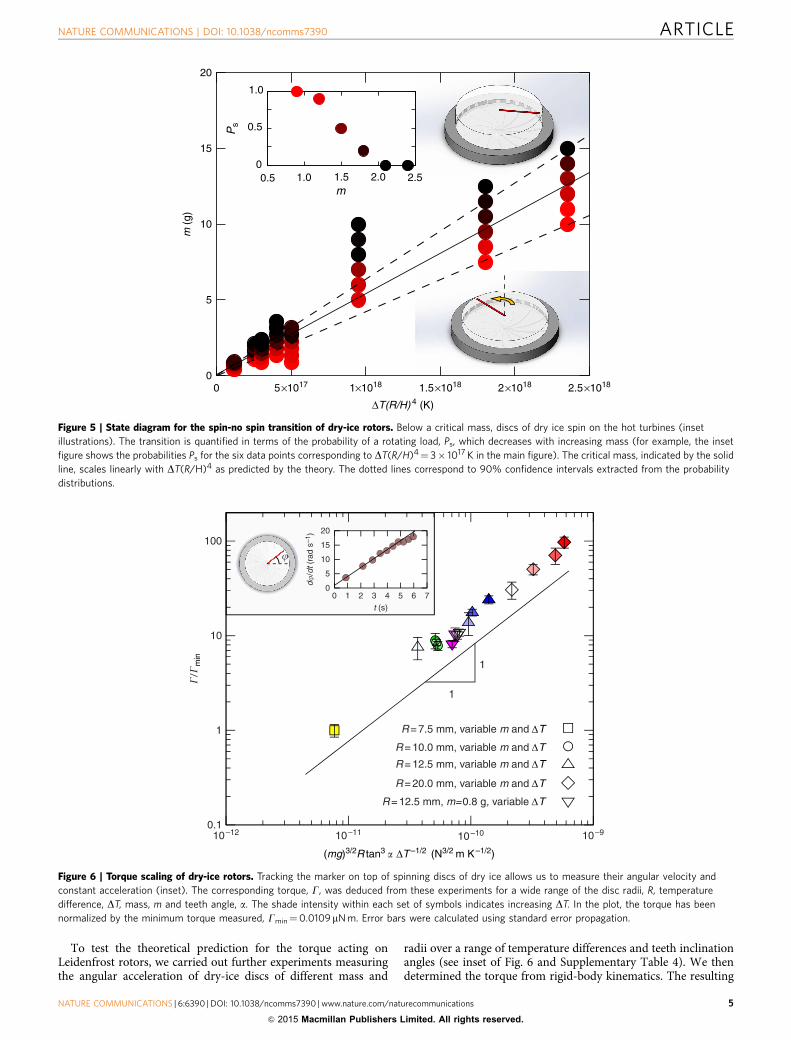
DiscussionTo test our prediction for the critical mass for rotation,equation (8), we carried out experiments over a wide range inthe temperature difference, disc radius and average thickness ofthe turbine teeth (See Supplementary Tables 2 and 3). For eachset of experimental conditions (DT, R, H), we measured theprobability of rotation of the disc, Ps(m), for a wide range in themass of the loads, m (typically 60 trials). The inset of Fig. 5 showsa typical probability curve, showing the transition to rotation asthe mass of the discs is reduced. The experimental state diagramshown in Fig. 5 confirms the scaling of the critical mass, definedas Ps(mc)¼ 0.5, with DT(R/H)4, as predicted by equation (8).
r�
z
h
H
Viscous drag
Flow
l(r)
Vapourfilm
Figure 4 | Rectification mechanism for Leidenfrost rotation. The vapour
released by the CO2 disc or the water film creates a layer of thickness h
between the surface of the turbine and the levitating surface. The
underlying pattern drives the vapour flow downhill along the teeth. The
resulting viscous drag drives the rotation of the levitating surface.
ARTICLE NATURE COMMUNICATIONS | DOI: 10.1038/ncomms7390
4 NATURE COMMUNICATIONS | 6:6390 | DOI: 10.1038/ncomms7390 | www.nature.com/naturecommunications
& 2015 Macmillan Publishers Limited. All rights reserved.
To test the theoretical prediction for the torque acting onLeidenfrost rotors, we carried out further experiments measuringthe angular acceleration of dry-ice discs of different mass and
radii over a range of temperature differences and teeth inclinationangles (see inset of Fig. 6 and Supplementary Table 4). We thendetermined the torque from rigid-body kinematics. The resulting
1.0
00.5 1.0 1.5 2.0 2.5
0.5
20
15
10
5
00 5×10¹⁷ 1×10¹⁸ 1.5×10¹⁸ 2×10¹⁸ 2.5×10¹⁸
ΔT(R/H) 4 (K)
m (
g)
Ps
m
Figure 5 | State diagram for the spin-no spin transition of dry-ice rotors. Below a critical mass, discs of dry ice spin on the hot turbines (inset
illustrations). The transition is quantified in terms of the probability of a rotating load, Ps, which decreases with increasing mass (for example, the inset
figure shows the probabilities Ps for the six data points corresponding to DT(R/H)4¼ 3� 1017 K in the main figure). The critical mass, indicated by the solid
line, scales linearly with DT(R/H)4 as predicted by the theory. The dotted lines correspond to 90% confidence intervals extracted from the probability
distributions.
�/�
min
100
10
1
0.110–12
(mg)3/2R tan3 � ΔT –1/2 (N3/2 m K–1/2)
10–11 10–10 10–9
�
d�/d
t (ra
d s–
1 )
20
15
10
5
00
t (s)
1
1
2
R = 7.5 mm, variable m and ∆T
R = 10.0 mm, variable m and ∆T
R = 12.5 mm, variable m and ∆T
R = 20.0 mm, variable m and ∆T
R = 12.5 mm, m=0.8 g, variable ∆T
3 4 5 6 7
1
Figure 6 | Torque scaling of dry-ice rotors. Tracking the marker on top of spinning discs of dry ice allows us to measure their angular velocity and
constant acceleration (inset). The corresponding torque, G, was deduced from these experiments for a wide range of the disc radii, R, temperature
difference, DT, mass, m and teeth angle, a. The shade intensity within each set of symbols indicates increasing DT. In the plot, the torque has been
normalized by the minimum torque measured, Gmin¼0.0109mN m. Error bars were calculated using standard error propagation.
NATURE COMMUNICATIONS | DOI: 10.1038/ncomms7390 ARTICLE
NATURE COMMUNICATIONS | 6:6390 | DOI: 10.1038/ncomms7390 | www.nature.com/naturecommunications 5
& 2015 Macmillan Publishers Limited. All rights reserved.
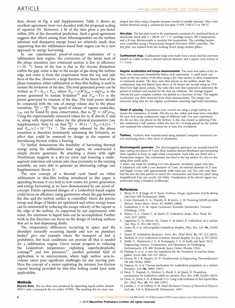
data, shown in Fig. 6 and Supplementary Table 5, shows anexcellent agreement (over two decades) with the proposed scalingof equation (9). Moreover, a fit of the data gives a pre-factorwithin 20% of the theoretical prediction. Such a good agreementsuggests that effects arising from inhomogeneities on the turbinesubstrate and dissipative energy losses are relatively small, thussupporting that the sublimation-based heat engine can be a newapproach to energy harvesting.
In our experimental proof-of-concept realization of asublimation heat engine, the conversion of the latent heat ofthe phase transition into rotational motion is low in efficiency(B10� 6). Some of the loss is due to the viscous dissipationwithin the gap, some is due to the escape of gas along the turbineedge and some is from the evaporation from the top and sidefaces of the disc. However, a large fraction of the latent heat of thephase transition, either sublimation or thin-film boiling, is used tosustain the levitation of the disc. The total generated power can bewritten as P¼Plevþ Prot, where Plev¼ (pR2patmþmg)vn0 is thepower generated to sustain levitation15 and Prot¼Go is thepower generated by rotation of the disc. The total power shouldbe compared with the rate of energy release due to the phasetransition, DQin
Dt ¼ sdmdt . The speed of release of vapour molecules,
vn0, can be found by mass conservation, that is, dmdt � pR2rvn0.
Using the experimentally measured values for m, R, dm/dt, G ando, along with reported values for the physical parameters (seeSupplementary Note 1), we find DQin
Dt ’ 30 J s� 1, PlevC4.2 J s� 1
and ProtC2� 10� 5 J s� 1. The energy released by the phasetransition is therefore dominantly sustaining the levitation, aneffect that could be removed by design at the expense ofintroducing friction within a bearing.
To further demonstrate the feasibility of harvesting thermalenergy using the sublimation heat engine, we constructed asimple electric generator. By attaching a frame with eightNeodynium magnets to a dry-ice rotor and lowering a multi-segment induction coil system into close proximity to the rotatingassembly, we were able to generate an alternating voltage (seeSupplementary Movie 3).
The new concept of a thermal cycle based on eithersublimation or thin-film boiling introduced in this paper isappealing because it can lead to new routes for power generationand energy harvesting as we have demonstrated by our proof-of-concept. Future optimized designs of a Leidenfrost-based enginecould focus on efficiency using geometries where the gap betweenthe disc and the turbine surface is controlled, where the precisesweep and shape of blades are optimized and where energy lossescan be minimized by reducing the escape velocity of the vapour atthe edge of the turbine. As supported by our experiments withwater, the extension to liquid fuels can be accomplished. Furtherwork in this direction can focus on the design of wicking surfacesthat act as fuel-dispensing shafts.
The temperature differences occurring in space and theabundant naturally occurring liquids and ices on planetarybodies9 give one example where the transport of fuel isprohibitive, but local conditions can provide all that is neededfor a sublimation engine. Given recent progress in reducingthe Leidenfrost temperature exploiting superhydrophobiccoatings16 and low pressures17, another potential field ofapplication is in microsystems, where high surface area-to-volume ratios pose significant challenges for any moving part.Here the concept of a motor exploiting the intrinsic low-frictionvapour bearing provided by thin-film boiling could have wideapplicability.
MethodsDry-ice discs. Dry-ice discs were produced by depositing liquid carbon dioxide(BOC) onto a snowpack dry-ice maker (VWR). The resulting dry-ice snow was
shaped into discs using a bespoke pressure mould of variable diameter. Discs werefurther flattened using a commercial hot plate (VWR VMS-C7) at 150 �C.
Hot plate. The hot plate used in the experiments consisted of a machined block ofaluminium fitted with 2� 200 W 1/20 0 � 30 0 cartridge heaters (RS Components)and a K-type thermocouple to monitor the temperature. The cartridge heaterswere controlled using a Proportional-Integral-Derivative (PID) controller. Thehot plate was isolated from the working bench using ceramic pillars.
Confinement rings. Confinement rings were made from a stock steel bar and wereturned on a lathe to have a desired internal diameter and a square cross section of5� 5 mm.
Angular acceleration and torque measurements. The mass and radius of dry-icediscs were measured immediately before each experiment. A small mark wasmade on the top surface of the discs using a dry-wipe marker to allow visualizationof rotational motion. The discs were then placed on the turbine, inside theconfinement ring and filmed from above at 50 frames per second using an SVSiMemView high-speed camera. The video files were then analyzed to determine theperiod of rotation and tracked for the first six rotations. The average angularvelocity for each complete rotation was plotted as a function of time. The angularacceleration was then extracted from these measurements. The torque wasextracted using data for the angular acceleration assuming rigid-body kinematics.
Onset of spinning. Experiments were carried out using a single turbine toensure the consistency of results. The dry-ice disc radius and mass were controlledfor each trial using confinement rings of different radii. For each experimentthe dry-ice disc was placed on the turbine. A disc was classed as spinning if thedisc underwent a full rotation within the first 10 s of being placed on the turbineand sustained the rotational motion for at least five revolutions.
Turbines. Turbines were manufactured using standard computer numerical con-trol machining from a thin sheet of aluminium.
Electromagnetic generator. The electromagnetic generator was manufactured bylaser cutting two pieces of 3-mm thick medium-density fibreboard and laminatingthem together to form an eight-lobed commutator. Each lobe was fitted with aNeodynium magnet. The commutator was fixed to the top surface of a dry-ice discusing three small tacks.A stator was made by winding 0.15-mm diameter varnished copper wire into8 cylindrical coils with a core diameter of 7 mm, an external diameter of 27 mmand length 12 mm, with approximately 4,000 turns per coil. The coils were thenlaid flat into the lobe pattern to match the commutator and fixed into place usingSampleKwick Fast cure acrylic (20-3560). Visualization of the electric signal wasperformed using a standard oscilloscope.
References1. Bloch, H. P. & Singh, M. P. Steam Turbines: Design, Application And Re-Rating
(McGraw Hill Professional, 2008).2. Cook-Chennault, K. A., Thambi, N. & Sastry, A. M. Powering MEMS portable
devices. Smart Mater. Struct. 17, 043001 (2008).3. Leidenfrost, J. G. De Aquae Communis Nonnullis Qualitatibus Tractatus
(Duisburg, 1756).4. Biance, A.-L., Clanet, C. & Quere, D. Leidenfrost drops. Phys. Fluids 15,
1632–1637 (2003).5. Lagubeau, G., Le Merrer, M., Clanet, C. & Quere, D. Leidenfrost on a ratchet.
Nat. Phys. 7, 395–398 (2011).6. Linke, H. et al. Self-propelled Leidenfrost droplets. Phys. Rev. Lett. 96, 154502
(2006).7. Quere, D. Leidenfrost dynamics. Annu. Rev. Fluid Mech. 45, 197–215 (2013).8. Hashmi, A. et al. Leidenfrost levitation: beyond droplets. Sci. Rep. 2, 797 (2012).9. Sibille, L., Mantovani, J. G. & Dominguez, J. A. in Earth and Space 2012:
Engineering, Science, Construction, and Operations in ChallengingEnvironments, 479–488 (Kennedy Space Center, Florida, USA).
10. Diniega, S. et al. A new dry hypothesis for the formation of martian lineargullies. Icarus 225, 526–537 (2013).
11. Moran, M. J. & Shapiro, H. N. Fundamentals of Engineering Thermodynamics5th edn (Wiley, 2006).
12. Dupeux, G. et al. Viscous mechanism for Leidenfrost propulsion on a ratchet.Europhys. Lett. 96, 58001 (2011).
13. Baier, T., Dupeux, G., Herbert, S., Hardt, S. & Quere, D. Propulsionmechanisms for Leidenfrost solids on ratchets. Phys. Rev. E 87, 021001 (2013).
14. Oron, A., Davis, S. H. & Bankoff, S. G. Long-scale evolution of thin liquid films.Rev. Mod. Phys. 69, 931–980 (1997).
15. Landau, L. D. & Lifshitz, E. M. Fluid Mechanics (Course of Theoretical Physics).2nd edn, Vol. 6, Butterworth Heinemann, 1987).
ARTICLE NATURE COMMUNICATIONS | DOI: 10.1038/ncomms7390
6 NATURE COMMUNICATIONS | 6:6390 | DOI: 10.1038/ncomms7390 | www.nature.com/naturecommunications
& 2015 Macmillan Publishers Limited. All rights reserved.

16. Vakarelski, I. U., Patankar, N. A., Marston, J. O., Chan, D. Y. C. & Thoroddsen,S. T. Stabilization of Leidenfrost vapour layer by textured superhydrophobicsurfaces. Nature 489, 274–277 (2012).
17. Celestini, F., Frisch, T. & Pomeau, Y. Room temperature water Leidenfrostdroplets. Soft Matter 9, 9535–9538 (2013).
AcknowledgementsWe thank Dr J. Martin (Reece Innovation), Dr A. Stokes and Professor A. J. Walton(University of Edinburgh) and Professor R. Bennacer (ENS-Cachan, France) for usefuldiscussions; and the Faculty of Engineering and Environment at Northumbria Universityand the School of Engineering at the University of Edinburgh for technical support.
Author contributionsThe study was jointly conceived, developed and designed. K.S. designed and producedthe turbines. G.G.W. carried out the experiments. G.G.W. and R.L.-A. analyzed the data.R.L.-A. developed the theoretical model. G.G.W. designed the proof-of-concept engine.R.L.-A. and G.M. wrote the paper with contributions from G.G.W. and K.S.
Additional informationSupplementary Information accompanies this paper at http://www.nature.com/naturecommunications
Competing financial interests: The authors declare no competing financial interests.
Reprints and permission information is available online at http://npg.nature.com/reprintsandpermissions/
How to cite this article: Wells, G. G. et al. A sublimation heat engine. Nat. Commun.6:6390 doi: 10.1038/ncomms7390 (2015).
This work is licensed under a Creative Commons Attribution 4.0International License. The images or other third party material in this
article are included in the article’s Creative Commons license, unless indicated otherwisein the credit line; if the material is not included under the Creative Commons license,users will need to obtain permission from the license holder to reproduce the material.To view a copy of this license, visit http://creativecommons.org/licenses/by/4.0/
NATURE COMMUNICATIONS | DOI: 10.1038/ncomms7390 ARTICLE
NATURE COMMUNICATIONS | 6:6390 | DOI: 10.1038/ncomms7390 | www.nature.com/naturecommunications 7
& 2015 Macmillan Publishers Limited. All rights reserved.
Related Documents