A Study of On-Line and Off-Line Turbine Washing to Optimize the Operation of a Gas Turbine Meherwan P. Boyce, Ph.D., P.E. Fellow ASME The Boyce Consultancy Group, LLC. Houston TX. Francisco Gonzalez Enterprise Products Company Mont Belvieu TX. Keywords: Gas Turbines, Compressors, Performance, Heat Rate, Efficiency, Cleaning, Solvents ABSTRACT This paper highlights the procedure followed in order to establish an effective on-line and off line water wash program on a fleet of 36 small industrial turbines. To determine the efficacy of water washing a program of tests under controlled conditions was organized. With proper condition monitoring techniques, a set of tests were developed in order to identify the proper water wash frequency and the dissolving agent used to water wash. The goal of the water wash program is to maximize turbine power, and efficiency; while minimizing maintenance labor, and material. The Gas Turbine Compressor Isentropic Efficiency, the overall heat rate, and the overall thermal efficiency were used to compare the tests and evaluate the performance of different water wash frequencies and solvents. 8760 points defined each test as the data was taken over a one year time period, at a one hour interval. INTRODUCTION The new gas turbines are the corner stone of the rise of the combined cycle as the power source of the new millennium. The new gas turbines have a very high-pressure ratio, a high firing temperature, and in some case a reheat burner in the gas turbine. The gas turbines have also new Dry low NO x combustors. The combination of all these components has dramatically increased the thermal efficiency of the gas turbine. The gas turbine since the early sixties has gone from efficiencies as low 15%-17% to efficiencies around 45%. This has been due to the pressure ratio increase from around 7:1 to as high as 30:1, and an increase in the firing temperature from about 1500ºF (815°C) to about 2500ºF (1371°C). With these changes we have also seen the efficiency of the major components in the gas turbine increase dramatically. The gas turbine compressor efficiency increased from around 78% - 87%; the combustor efficiency from about 94%-98%, and the turbine expander efficiency from about 84% - 92%. The higher pressure ratio compressors are subject to fouling, and can result in surge problems or blade excitation problems, which lead to blade failure. The effect of Compressor fouling is also very important on the overall performance of the gas turbine since it uses nearly 60% of the work generated by the gas turbine. The effect of fouling of the compressor which reduces the compressor efficiency, leads to a reduction in the overall efficiency. The cleaning of these blades by on line water washing is a very important operational requirement. The practice of using abrasive cleaning by injecting walnut shells, rice or spent catalyst is being suspended in most new and old plants. Where used, it must be carefully evaluated; rice for instance is a very poor abrasive since it shatters and tends to get into seals, bearings and into the lubrication system. Walnut shells should never be used since they tend to collect inside the HRSG system and in some cases have been known to catch on fire. Abrasive Cleaning is replaced with On-Line Water Wash. 1 Copyright © 2005 by ASME Proceedings of GT2005 ASME Turbo Expo 2005: Power for Land, Sea and Air June 6-9, 2005, Reno-Tahoe, Nevada, USA GT2005-69126 Downloaded From: https://proceedings.asmedigitalcollection.asme.org on 07/01/2019 Terms of Use: http://www.asme.org/about-asme/terms-of-use

Welcome message from author
This document is posted to help you gain knowledge. Please leave a comment to let me know what you think about it! Share it to your friends and learn new things together.
Transcript
Do
A Study of On-Line and Off-Line Turbine Washing to Optimize the Operation of a Gas Turbine
Meherwan P. Boyce, Ph.D., P.E. Fellow ASME
The Boyce Consultancy Group, LLC. Houston TX.
Francisco Gonzalez
Enterprise Products Company Mont Belvieu TX.
Keywords: Gas Turbines, Compressors, Performance, Heat Rate, Efficiency, Cleaning, Solvents
Proceedings of GT2005ASME Turbo Expo 2005: Power for Land, Sea and Air
June 6-9, 2005, Reno-Tahoe, Nevada, USA
GT2005-69126
ABSTRACT
This paper highlights the procedure followed in order to establish an effective on-line and off line water wash program on a fleet of 36 small industrial turbines. To determine the efficacy of water washing a program of tests under controlled conditions was organized. With proper condition monitoring techniques, a set of tests were developed in order to identify the proper water wash frequency and the dissolving agent used to water wash. The goal of the water wash program is to maximize turbine power, and efficiency; while minimizing maintenance labor, and material. The Gas Turbine Compressor Isentropic Efficiency, the overall heat rate, and the overall thermal efficiency were used to compare the tests and evaluate the performance of different water wash frequencies and solvents. 8760 points defined each test as the data was taken over a one year time period, at a one hour interval. INTRODUCTION
The new gas turbines are the corner stone of the rise of the combined cycle as the power source of the new millennium. The new gas turbines have a very high-pressure ratio, a high firing temperature, and in some case a reheat burner in the gas turbine. The gas turbines have also new Dry low NOx combustors. The combination of all these components has dramatically increased the thermal efficiency of the gas turbine. The gas turbine since the early sixties has gone from
wnloaded From: https://proceedings.asmedigitalcollection.asme.org on 07/01/2019 Terms of
efficiencies as low 15%-17% to efficiencies around 45%. This has been due to the pressure ratio increase from around 7:1 to as high as 30:1, and an increase in the firing temperature from about 1500ºF (815°C) to about 2500ºF (1371°C). With these changes we have also seen the efficiency of the major components in the gas turbine increase dramatically. The gas turbine compressor efficiency increased from around 78% - 87%; the combustor efficiency from about 94%-98%, and the turbine expander efficiency from about 84% - 92%. The higher pressure ratio compressors are subject to fouling, and can result in surge problems or blade excitation problems, which lead to blade failure. The effect of Compressor fouling is also very important on the overall performance of the gas turbine since it uses nearly 60% of the work generated by the gas turbine. The effect of fouling of the compressor which reduces the compressor efficiency, leads to a reduction in the overall efficiency. The cleaning of these blades by on line water washing is a very important operational requirement. The practice of using abrasive cleaning by injecting walnut shells, rice or spent catalyst is being suspended in most new and old plants. Where used, it must be carefully evaluated; rice for instance is a very poor abrasive since it shatters and tends to get into seals, bearings and into the lubrication system. Walnut shells should never be used since they tend to collect inside the HRSG system and in some cases have been known to catch on fire. Abrasive Cleaning is replaced with On-Line Water Wash.
1 Copyright © 2005 by ASME
Use: http://www.asme.org/about-asme/terms-of-use
D
In many plants On-Line Water Wash procedures have contributed literally hundreds of thousands of dollars to the bottom line.
NOMENCLATURE • A = Availability • cp = Specific heat at constant pressure • cv = Specific heat at constant volume • EFH = Equivalent forced outage hours • FO = Forced Outage Hours • H = Enthalpy • HO = Hours of operation at reduced load. • LHV = Lower Heating Value • m = Mass flow of air • mf= Mass flow of fuel • MWd = Desired Output corrected to the design or
reference conditions. This must be equal to or less than the plant load measured and corrected to the design or reference conditions at the acceptance test.
• MWa = Actual maximum acceptance test produced and corrected to the design or reference conditions.
• n = Polytropic exponent • Nstg = Number of Stages • • P = Pressure • PT = Time Period (8760 hrs/year) • PM = Planned Maintenance Hours • R = Reliability • T = Temperature • Wc = Work Compressor • Wpc = Work at Generator • Wstg = Compressor Work per Stage
Greek Symbols γ = Adiabatic Polytropic Exponent (cp/cv) ηad = Compressor Adiabatic Efficiency ηmt = Mechanical Efficiency ηp = Compressor Polytropic Efficiency ηth = Overall Total Efficiency
.
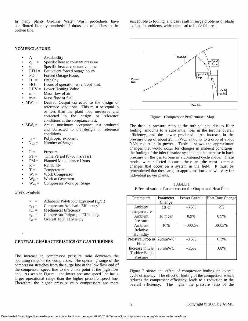
GENERAL CHARACTERISTICS OF GAS TURBINES The increase in compressor pressure ratio decreases the operating range of the compressor. The operating range of the compressor stretches from the surge line at the low flow end of the compressor speed line to the choke point at the high flow end. As seen in Figure 1 the lower pressure speed line has a larger operational range than the higher pressure speed line. Therefore, the higher pressure ratio compressors are more
ownloaded From: https://proceedings.asmedigitalcollection.asme.org on 07/01/2019 Terms of Use
susceptible to fouling, and can result in surge problems or blade excitation problems, which can lead to blade failures.
Figure 1 Compressor Performance Map
The drop in pressure ratio at the turbine inlet due to filter fouling, amounts to a substantial loss in the turbine overall efficiency, and the power produced. An increase in the pressure drop of about 25mm.WC. amounts to a drop of about 0.3% reduction in power. Table 1 shows the approximate changes that would occur for changes in ambient conditions; the fouling of the inlet filtration system and the increase in back pressure on the gas turbine in a combined cycle mode. These modes were selected because these are the most common changes that occur on a system in the field. It must be remembered that these are just approximations and will vary for individual power plants.
TABLE 1
Effect of various Parameters on the Output and Heat Rate
Parameters Parameter Change
Power Output Heat Rate Change
Ambient Temperature
10°C -6.5% 2%
Ambient Pressure
10 mbar
0.9% 0.9%
Ambient Relative
Humidity
10% -.0002% .0005%
Pressure Drop in Filter
25mmWC -0.5% 0.3%
Increase in Gas Turbine Back
Pressure
25mmWC -.25% .08%
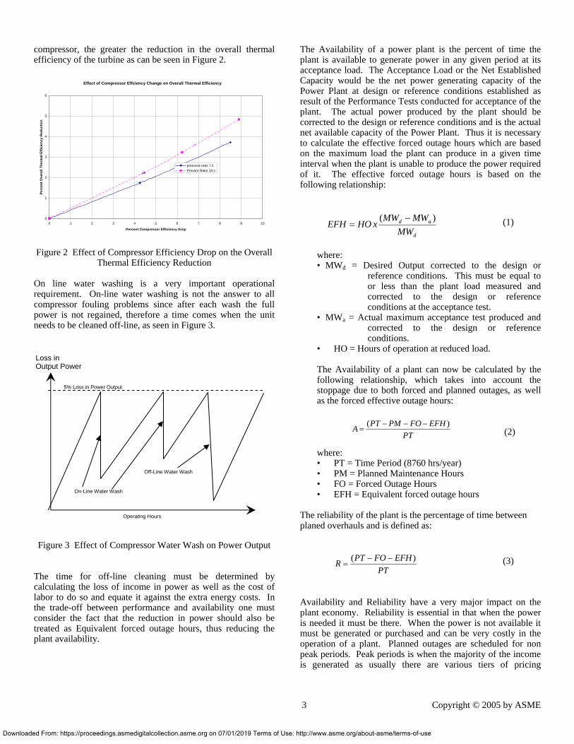
Figure 2 shows the effect of compressor fouling on overall cycle efficiency. The effect of fouling of the compressor which reduces the compressor efficiency, leads to a reduction in the overall efficiency. The higher the pressure ratio of the
2 Copyright © 2005 by ASME
: http://www.asme.org/about-asme/terms-of-use
Down
compressor, the greater the reduction in the overall thermal efficiency of the turbine as can be seen in Figure 2.
Effect of Compressor Effciency Change on Overall Thermal Efficiency
0
1
2
3
4
5
6
0 1 2 3 4 5 6 7 8 9 10
Percent Compressor Efficiency Drop
Perc
ent O
vera
ll Th
erm
al E
ffici
ency
Red
uctio
n
pressure ratio 7:1Pressre Ratio 15:1
Figure 2 Effect of Compressor Efficiency Drop on the Overall Thermal Efficiency Reduction
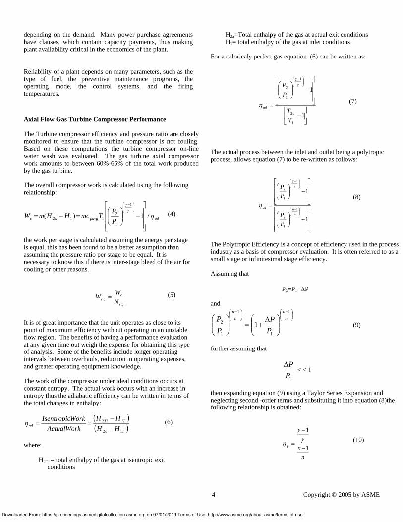
On line water washing is a very important operational requirement. On-line water washing is not the answer to all compressor fouling problems since after each wash the full power is not regained, therefore a time comes when the unit needs to be cleaned off-line, as seen in Figure 3.
Figure 3 Effect of Compressor Water Wash on Power Output The time for off-line cleaning must be determined by calculating the loss of income in power as well as the cost of labor to do so and equate it against the extra energy costs. In the trade-off between performance and availability one must consider the fact that the reduction in power should also be treated as Equivalent forced outage hours, thus reducing the plant availability.
Loss in Output Power
Operating Hours
On-Line Water Wash
Off-Line Water Wash
5% Loss in Power Output
loaded From: https://proceedings.asmedigitalcollection.asme.org on 07/01/2019 Terms of Us
The Availability of a power plant is the percent of time the plant is available to generate power in any given period at its acceptance load. The Acceptance Load or the Net Established Capacity would be the net power generating capacity of the Power Plant at design or reference conditions established as result of the Performance Tests conducted for acceptance of the plant. The actual power produced by the plant should be corrected to the design or reference conditions and is the actual net available capacity of the Power Plant. Thus it is necessary to calculate the effective forced outage hours which are based on the maximum load the plant can produce in a given time interval when the plant is unable to produce the power required of it. The effective forced outage hours is based on the following relationship:
d
ad
MWMWMW
xHOEFH)( −
= (1)
where: • MWd = Desired Output corrected to the design or
reference conditions. This must be equal to or less than the plant load measured and corrected to the design or reference conditions at the acceptance test.
• MWa = Actual maximum acceptance test produced and corrected to the design or reference conditions.
• HO = Hours of operation at reduced load. The Availability of a plant can now be calculated by the following relationship, which takes into account the stoppage due to both forced and planned outages, as well as the forced effective outage hours: (2)
where: • PT = Time Period (8760 hrs/year) • PM = Planned Maintenance Hours • FO = Forced Outage Hours • EFH = Equivalent forced outage hours
The reliability of the plant is the percentage of time between planed overhauls and is defined as:
PTEFHFOPTR )( −−
= (3)
Availability and Reliability have a very major impact on the plant economy. Reliability is essential in that when the power is needed it must be there. When the power is not available it must be generated or purchased and can be very costly in the operation of a plant. Planned outages are scheduled for non peak periods. Peak periods is when the majority of the income is generated as usually there are various tiers of pricing
PTEFHFOPMPTA )( −−−
=
3 Copyright © 2005 by ASME
e: http://www.asme.org/about-asme/terms-of-use
s
Dow
depending on the demand. Many power purchase agreements have clauses, which contain capacity payments, thus making plant availability critical in the economics of the plant.
Reliability of a plant depends on many parameters, such as the type of fuel, the preventive maintenance programs, the operating mode, the control systems, and the firing temperatures.
Axial Flow Gas Turbine Compressor Performance The Turbine compressor efficiency and pressure ratio are closelymonitored to ensure that the turbine compressor is not foulingBased on these computations the turbine compressor on-linewater wash was evaluated. The gas turbine axial compressorwork amounts to between 60%-65% of the total work producedby the gas turbine. The overall compressor work is calculated using the following relationship:
adpavgac PP
TmcHHmW ηγγ
/1)(
1
1
2112
⎥⎥⎥
⎦
⎤
⎢⎢⎢
⎣
⎡−⎟⎟
⎠
⎞⎜⎜⎝
⎛=−=
⎟⎟⎠
⎞⎜⎜⎝
⎛ −
(4)
the work per stage is calculated assuming the energy per stage is equal, this has been found to be a better assumption than assuming the pressure ratio per stage to be equal. It is necessary to know this if there is inter-stage bleed of the air for cooling or other reasons.
stg
cstg N
WW = (5)
It is of great importance that the unit operates as close to its point of maximum efficiency without operating in an unstable flow region. The benefits of having a performance evaluation at any given time out weigh the expense for obtaining this type of analysis. Some of the benefits include longer operating intervals between overhauls, reduction in operating expenses, and greater operating equipment knowledge. The work of the compressor under ideal conditions occurs at constant entropy. The actual work occurs with an increase in entropy thus the adiabatic efficiency can be written in terms of the total changes in enthalpy:
( )( )Ta
ITTIad HH
HHActualWork
WorkIsentropic
12
2
−−
==η (6)
where:
H2TI = total enthalpy of the gas at isentropic exit conditions
nloaded From: https://proceedings.asmedigitalcollection.asme.org on 07/01/2019 Terms of
.
H2a=Total enthalpy of the gas at actual exit conditions H1= total enthalpy of the gas at inlet conditions
For a caloricaly perfect gas equation (6) can be written as:
⎥⎦
⎤⎢⎣
⎡−
⎥⎥⎥
⎦
⎤
⎢⎢⎢
⎣
⎡−⎟⎟
⎠
⎞⎜⎜⎝
⎛
=
⎟⎟⎠
⎞⎜⎜⎝
⎛ −
1
1
1
2
1
1
2
TT
PP
aad
γγ
η (7)
The actual process between the inlet and outlet being a polytropic process, allows equation (7) to be re-written as follows:
⎥⎥⎥
⎦
⎤
⎢⎢⎢
⎣
⎡−⎟⎟
⎠
⎞⎜⎜⎝
⎛
⎥⎥⎥
⎦
⎤
⎢⎢⎢
⎣
⎡−⎟⎟
⎠
⎞⎜⎜⎝
⎛
=⎟⎠⎞
⎜⎝⎛ −
⎟⎟⎠
⎞⎜⎜⎝
⎛ −
1
1
1
1
2
1
1
2
nnad
PP
PP γ
γ
η (8)
The Polytropic Efficiency is a concept of efficiency used in the procesindustry as a basis of compressor evaluation. It is often referred to as asmall stage or infinitesimal stage efficiency. Assuming that
P2=P1+∆P and
⎟⎠⎞
⎜⎝⎛ −
⎟⎠⎞
⎜⎝⎛ −
⎟⎟⎠
⎞⎜⎜⎝
⎛ ∆+=⎟⎟
⎠
⎞⎜⎜⎝
⎛ nn
nn
PP
PP
1
1
1
1
2 1 (9)
further assuming that
1PP∆
< < 1
then expanding equation (9) using a Taylor Series Expansion and neglecting second -order terms and substituting it into equation (8)the following relationship is obtained:
nnp 1
1
−
−
=γ
γ
η (10)
4 Copyright © 2005 by ASME
Use: http://www.asme.org/about-asme/terms-of-use
Downl
Overall Turbine Efficiency
The overall thermal efficiency of the gas turbine in a simple cycle (varies between 25% -47% depending on the turbine) is computed to determine deterioration of the turbine:
InputHeatOutputPower
th =η
100LHVm
W
f
mt
pc
thη
η = (11)
Heat rate of the turbine
The heat rate can now be easily computed
100
4.2544th
HRη
= (12)
where:
HR = Heat rate (BTU/hp-hr)
Compressor Water Wash
On-Line and Off-Line Compressor washing is a very important part of gas turbine operations. Two approaches to compressor cleaning are abrasion and solvent cleaning. The use of abrasive cleaning has diminished due to erosion problems, liquid washing is now primarily being used. The new high pressure compressors are very susceptible to dirt on the blades which not only can lead to a reduction in performance but can also lead to compressor surge. Washing efficacy is site specific due to the different environmental conditions at each plant. There are many excellent techniques and systems for water washing. Operators must often determine the best approach for their gas turbines. This includes what solvents if any should be used, and the frequencies of wash. This is a complex technical-economical problem also depending on the service that the gas turbines are in and the plant surroundings.
Off-Line water washing (with or without detergents) cleans by water impact and by removing the water-soluble salts. It is important that the water used should be demineralized water. The detergent/water ratio, is also another important parameter. Water washing using a water-soap mixture is an efficient
oaded From: https://proceedings.asmedigitalcollection.asme.org on 07/01/2019 Terms of Us
method of cleaning. This cleaning is most effective when carried out in several steps, which involve the application of a soap and water solution, followed by several rinse cycles. Each rinse cycle involves the acceleration of the machine to approximately 20%-50%of the starting speed, after which the machine is allowed to coast to a stop. A soaking period follows during which the soapy water solution may work on dissolving the salt. A fraction of airborne salt always passes through the filter. The method recommended for determining whether or not the foulants have a substantial salt base, is to soap wash the turbine and collect the water from all drainage ports available. Dissolved salts in the water can then be analyzed. Online washing is being widely used as a means to control fouling by keeping the problem from developing. The effect of water cleaning is usually not very effective after the first few stages. Techniques and wash systems have evolved to a point where this can be done effectively and safely. Washing can be accomplished by using water, water based solvents, petroleum based solvents or surfactants. The solvents work by dissolving the contaminants while surfactants work by chemically reacting with the foulants. Water based solvents are effective against salt, but fare poorly against oily deposits. Petroleum based solvents do not effectively remove salty deposits. With solvents, there is a chance of foulants being re-deposited in the latter compressor stages. Even with good filtration, salt can collect in the compressor section. During the collection process of both salt and other foulants, an equilibrium condition is quickly reached, after which re-ingestion of large particles occurs. This re-ingestion has to be prevented by the removal of salt from the compressor prior to saturation. The rate at which saturation occurs is highly dependent on filter quality. In general, salts can safely pass through the turbine when gas and metal temperatures are less than 1000 F. Aggressive attacks will occur if the temperatures are much higher. During cleaning, the actual instantaneous rates of salt passage are very high together with greatly increased particle size. Plant Equipment Enterprise Products Mont Belvieu Plant operates 36 gas turbines. The gas turbines are used to compress process gases in heat pump, refrigeration process and power generation. 28 of the turbines are used in mechanical drives, and 8 of the turbines are used in power generation. All of the turbines are used in a hot oil combine cycle that helps recover the energy in the waste heat. Most of the gas turbines are in the 4000 Hp range, but the largest turbine is a 15000 Hp Mars turbine driving a process gas axial compressor. Thirty-three of the thirty-six gas turbines are equipped with on-line water wash capability. Gas Turbine Configuration The turbines used for all of the online water wash test were Solar T4702S Centaur generators. All of the turbines are
5 Copyright © 2005 by ASME
e: http://www.asme.org/about-asme/terms-of-use
Downl
configured identically, and all of the turbines have about the same amount of operating hours. These generator turbines are equipped with an inlet air pre-filter with primary filters made by Donaldson filters. The filter is configured with cylindrical/conical filter synthetic media. The filtration system is a Huff and Puff filter system. The filter efficiency is 99.5 on particles of 1-3 microns. The average pressure drop across the filters is 2.4 in. H2O. The Centaur engines coupled to a speed reducer gearbox and to a generator are capable of producing 3 MW. The turbine exhaust is routed to a heat recovery unit that heats up a hot oil media that is used for process purposes. The typical exhaust gas temperature is around 950ºF (510ºC) before the hot oil coils and 200ºF(93ºC) after the coils. Performance Deterioration of a Gas Turbine
A gas turbine engine requires frequent cleaning to maintain an efficient operation. Performance degradation in a gas turbine can be categorized as recoverable and non-recoverable. Recoverable performance is the deterioration in a gas turbine performance that can be recovered by engine cleaning or other wise known as an on-line and off-line water wash. Non-recoverable degradation is the performance deterioration of a gas turbine caused by internal engine component wear. The only way to recover the non-recoverable degradation is by performing a shop inspection and engine overhaul.
The rate at which a gas turbine deteriorates is primarily affected by the amount of contaminants that enter the turbine through the inlet air filters, ducts, water from evaporative coolers, fuel and the frequency as well as the thoroughness of engine water washing. At times there exists unusual site conditions that accelerate the gas turbine degradation. Unusual airborne contaminants from process mists, smoke, oil, and chemical releases, dust storms, sugar cane burning smoke, and other sources have been documented to accelerate engine degradation. It is for these reasons that a site-specific test program should be conducted in order to optimize the effectiveness of a turbine water wash program. Deterioration in turbine performance is indicated by one or more of the following conditions:
Slower engine acceleration Engine compressor surge or stall Lower power output Loss of engine compressor discharge pressure Increase in compressor discharge temperature
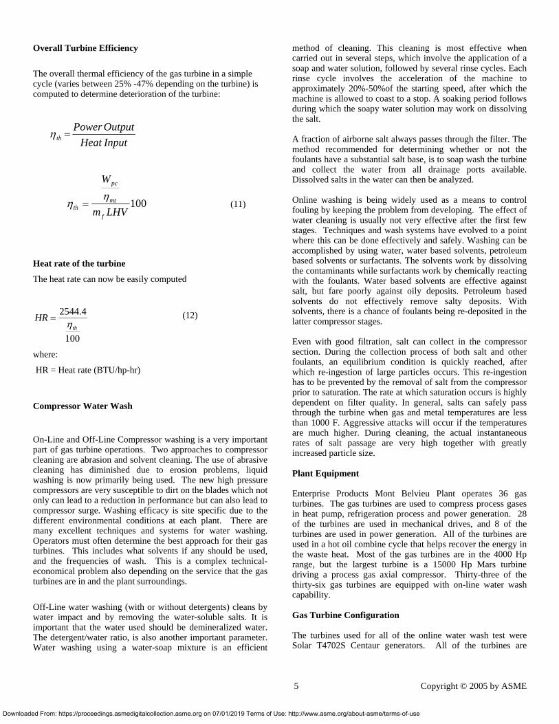
Figure 4 is a typical non-recoverable Power and Heat Rate degradation curve as a function of Equivalent Engine Operating Hours (EOH). With an increase in equivalent engine operating hours there is a sharp drop in delivered horsepower and an increase in the turbine heat rate during the first 5000 equivalent operating hours. These losses are non-recoverable in most cases, and would require the turbine to be returned to the shop, and new components would be needed.
oaded From: https://proceedings.asmedigitalcollection.asme.org on 07/01/2019 Terms of U
Non Recoverable Deterioration
0.95
0.96
0.97
0.98
0.99
1
1.01
1.02
1.03
0 5000 10000 15000 20000 25000
Equivalent Engine Operating Hours
Pow
er O
utpu
t
Hea
t Rat
e
Heat RatePower output
Figure 4 Non Recoverable Losses in a Gas Turbine as a
function of Equivalent Operating Hours
Different Wash Systems.
There are primarily three different types of wash systems: On-line wash system, off-line crank wash system, and manual hand held crank wash system. These cleaning systems are primarily designed to maintain the engine compressor at its maximum efficiency. The effectiveness of a system will greatly depend on their proper use. In order to evaluate the effectiveness of these systems it is strongly recommend to link the use of these systems to engine performance parameters.
For the most part, the on line wash system is intended as a supplement to the off-line crank wash system and not a substitute. In general, it is extremely important to implement a turbine crank wash program in order to recover most of the recoverable performance deterioration. At times when turbine crank washes are put off due to operating constraints, there may be the need to manually clean the turbine compressor blades, as a large build up of dirt will be on the blades. In order to manually clean the compressor blades the turbine compressor case has to be inspected and hand scrubbed in the field. Testing has revealed that an additional five efficiency points were recovered in a Mars turbine when an off-line water wash was performed. On-Line wash cleaning system The online wash cleaning system is used while the turbine operating parameters are stable. The system can be used without disturbing the operational unit, thus it does not matter if the turbine is operating at part or full load. Cleaning the turbine compressor with the online wash system should be a routine, and scheduled maintenance function. The on-line water wash system is based on injecting atomized cleaning fluid thus avoiding any problems that could be associated with abrasive cleaning methods that could erode blades, and damage component coatings.
6 Copyright © 2005 by ASME
se: http://www.asme.org/about-asme/terms-of-use
Down
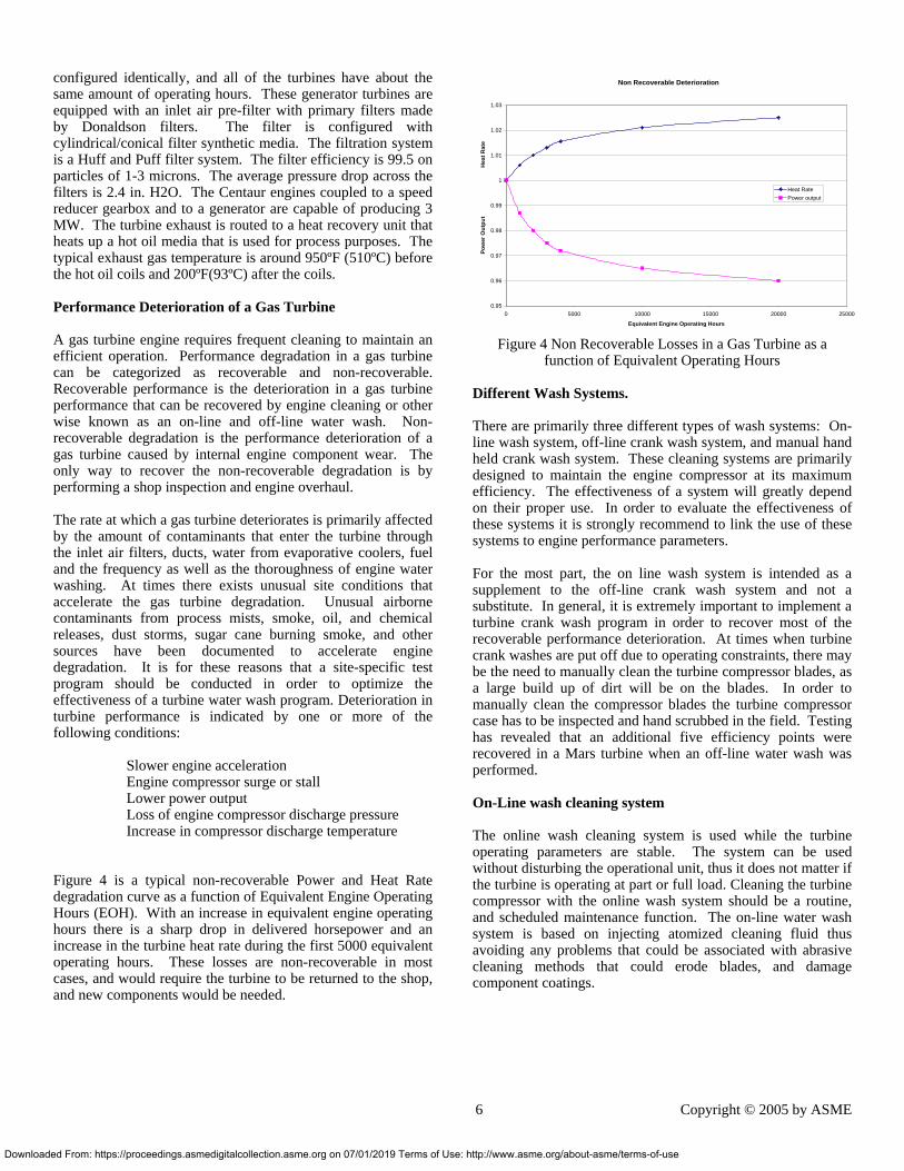
All of the gas turbines were equipped with an on-line water wash system as shown in Figure 5.
Figure 5 Water Wash System
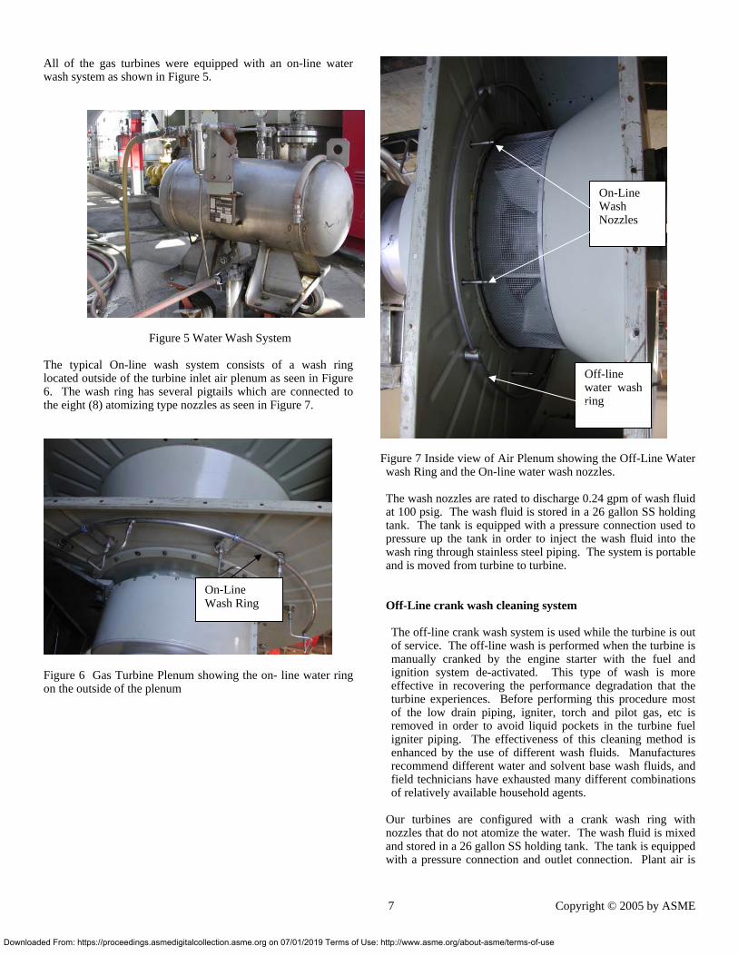
The typical On-line wash system consists of a wash ring located outside of the turbine inlet air plenum as seen in Figure 6. The wash ring has several pigtails which are connected to the eight (8) atomizing type nozzles as seen in Figure 7.
Figure 6 Gas Turbine Plenum showing the on- line water ring on the outside of the plenum
On-Line Wash Ring
loaded From: https://proceedings.asmedigitalcollection.asme.org on 07/01/2019 Terms of Use
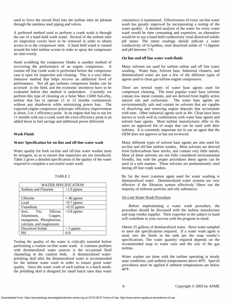
Figure 7 Inside view of Air Plenum showing the Off-Line Water wash Ring and the On-line water wash nozzles.
The wash nozzles are rated to discharge 0.24 gpm of wash fluid at 100 psig. The wash fluid is stored in a 26 gallon SS holding tank. The tank is equipped with a pressure connection used to pressure up the tank in order to inject the wash fluid into the wash ring through stainless steel piping. The system is portable and is moved from turbine to turbine. Off-Line crank wash cleaning system The off-line crank wash system is used while the turbine is out of service. The off-line wash is performed when the turbine is manually cranked by the engine starter with the fuel and ignition system de-activated. This type of wash is more effective in recovering the performance degradation that the turbine experiences. Before performing this procedure most of the low drain piping, igniter, torch and pilot gas, etc is removed in order to avoid liquid pockets in the turbine fuel igniter piping. The effectiveness of this cleaning method is enhanced by the use of different wash fluids. Manufactures recommend different water and solvent base wash fluids, and field technicians have exhausted many different combinations of relatively available household agents.
Our turbines are configured with a crank wash ring with nozzles that do not atomize the water. The wash fluid is mixed and stored in a 26 gallon SS holding tank. The tank is equipped with a pressure connection and outlet connection. Plant air is
Off-line water wash ring
On-Line Wash Nozzles
7 Copyright © 2005 by ASME
: http://www.asme.org/about-asme/terms-of-use
Down
used to force the mixed fluid into the turbine inlet air plenum through the stainless steel piping and valves.
A preferred method used to perform a crank wash is through the use of a hand held wash wand. Several of the turbine inlet air inspection covers have to be removed in order to obtain access in to the compressor inlet. A hand held wand is rotated around the inlet turbine screen in order to spray the compressor air inlet evenly.
Hand scrubbing the compressor blades is another method of recovering the performance of an engine compressor. A routine off line crank wash is performed before the compressor case is open for inspection and cleaning. This is a very labor-intensive method that helps recover an additional level of performance. Not all gas turbines compressor blades can be accessed in the field, and the economic incentives have to be evaluated before this method is undertaken. Currently we perform this type of cleaning on a Solar Mars 15000 SoLoNox turbine that has to operate 11 to 12 months continuously without any shutdowns while minimizing power loss. The expected engine compressor polytropic efficiency improvement is about .5 to 1 efficiency point. In an engine that has to run for 11 months with out a crank wash the extra efficiency point is an added boost in fuel savings and additional power delivered. Wash Fluids Water Specification for on-line and off-line water wash Water quality for both on-line and off-line water washes must be stringent, so as to ensure that impurities are not introduced. Table 2 gives a detailed specification of the quality of the water required to complete a successful water wash.
TABLE 2
WATER SPECIFICATION Sodium and Fluorine <1.9 ppmw Chlorine < 40 ppmw Lead <0.7 ppmw Vanadium <0.35 ppmw Iron, Tin, Silicon, Aluminum, Copper, manganese, Phosphorous, calcium, and magnesium
<3.8 ppmw
Dissolved Solids < 5 ppmw PH 6-9
Testing the quality of the water is critically essential before performing a routine on-line water wash. A common problem with demineralized water sources is the occasional fluid channeling in the catalyst beds. A demineralized water-polishing skid after the demineralized water is recommended for the turbine water wash in order to ensure good water quality. Since the water wash of each turbine is a batch mode, the polishing skid is designed for small batch rates thus water
loaded From: https://proceedings.asmedigitalcollection.asme.org on 07/01/2019 Terms of U
consistency is maintained. Effectiveness of every on-line water wash has greatly improved by incorporating a testing of the water quality. A detailed analysis of the water for every water wash would be time consuming and expensive, an alternative would be to use a hand held conductivity /total dissolved solids/ pH meter. The meter readings should indicate a water conductivity of<0.5µmhos, total dissolved solids of <1.0ppmw and pH between 7-9. On line and off line water wash fluids Many solvents are used for turbine online and off line water washing. Water base, Solvent base, Industrial cleaners, and demineralized water are just a few of the different types of agents used to clean gas turbine engine compressors. There are several types of water base agents used for compressor cleaning. The most popular water base solvents contain low metal contents, and are derived from highly active natural oils and surfactants. The water base agents are environmentally safe and contain no solvents that are capable of dissolving and removing engine deposits that accumulate with time. Other industrial agents such as Mr. Clean have been known to work well in combination with water base agents and solvent base agents. Most turbine manufactures offer to the users an approved list of soaps that can be used with their turbines. It is extremely important not to use an agent that the OEM does not approve or has not reviewed. Many different types of solvent base agents are also used for on-line and off-line turbine washes. Most solvents are derived form hydrocarbons base stocks, and contain very little metals. Most of these solvents are not fully considered environmental friendly, but with the proper procedures these agents can be used in a safe manner. These solvents are predominantly used during off line crank washes. By far the most common agent used for water washing is demineralized water. Demineralized water systems are very effective if the filtration system effectively filters out the majority of airborne particles and oily substances. On Line Water Wash Procedure
Before implementing a water wash procedure, the
procedure should be discussed with the turbine manufacture and soap vendor supplier. Their expertise in the subject in hand will contribute to your success with the program in mind. Obtain 25 gallons of demineralized water. Have water sampled to meet the specifications required. If a water wash agent is used, mix the fluids in the tank per the soap vendor’s specifications. The water quantity required depends on the recommended soap to water ratio and the size of the gas turbine. Water washes are done with the turbine operating at steady state conditions, and ambient temperatures above 40ºF. Special procedures must be applied if ambient temperatures are below 40ºF.
8 Copyright © 2005 by ASME
se: http://www.asme.org/about-asme/terms-of-use
Dow
Connect the outlet of the water wash cart to the turbine water wash piping. Connect the air hose supply to the tank air inlet valve, adjust the air pressure from your supply header to obtain 85 to 100 psig. Open the tank water wash fluid outlet valve and the turbine water wash inlet valve, which is connected to the water wash manifold. The wash fluid will be forced into the turbine by the air pressure in the tank. Observe turbine performance, the Compressor Discharge Pressure (CDP) will rise and firing temperature will drop, when the water is injected. Power will increase, but will not affect process variables. The turbine will have adequate power to maintain its set points.
• Observe the time it takes to ingest the 25 gallons of fluid.
• If the time to ingest the fluid increases with time, then the injection nozzles, are getting plugged.
• When the wash fluid ends, the turbine operation will continue with out any problems.
• If a wash solvent is used, follow this same procedure with a water only rinse
Off-line Crank Wash Procedure. Shut down the turbine and allow sufficient time for the turbine to cool below 150ºF (66ºC). This is extremely important if solvent base agents will be used for cleaning. Disconnect the lower case drain plug and igniter torch tubing, remove all low point tubing components such as the gas line to the fuel manifold, and install caps to all of the open lines. Remove the turbine inlet inspection covers Fill a hand held pump sprayer with the appropriate crank wash solution, water or solvent base agent with its appropriate water mixture. Initiate manual crank mode on the turbine engine. Spray the crank wash solution into turbine inlet air bell mouth. Continue this process until the wash solution is almost finished. Shut down the manual crank mode and continue to spray the solution during the engine coast down. Let the solution sit in the turbine for 10-15 minutes. Introduce 10 gallons of demineralized water into the crank wash water tank. Start manual crank mode, and inject the water into the crank wash manifold. For better results use the hand held injection wand. Care must be taken to make sure foreign objects are not sucked into the turbine air inlet, and that the protective foreign object screens are in place before starting this procedure. Inject a recommended detergent during turbine’s crank mode and during coast down. Let the solution sit for about 10-15 minutes. Fill injection cart with 20-30 gallons of demineralized water. Start manual turbine crank mode and inject water into turbine inlet bell mouth. You can either use the hand injection wand or use the water injection ring. Continue to inject demineralized water until you obtain a clean water stream out of the turbine drains.
nloaded From: https://proceedings.asmedigitalcollection.asme.org on 07/01/2019 Terms of U
Axial Compressor Instrumentation In order to properly assess the performance of the wash procedure, the compressor horsepower, fuel flow, inlet temperature and pressure, and engine compressor pressure and temperature. The axial flow compressors were instrumented so that detail data can be obtained. The axial flow compressor can and does foul so it is important to monitor its performance to ensure that its operation is in a stable region and operating close to its design point.
The pressure measurements are static measurements, the temperature measurements are total, since static temperatures cannot be measured in any practical manner. With the instrumentation available the performance deterioration on any given day can be computed. This instrumentation has been extremely helpful in identifying the associated problems with the axial compressor deterioration. The following is a list of the instrumentation on this axial compressor.
In order to perform a thorough engine performance evaluation the following parameters should be measured: Compressor Suction Static Pressure
Compressor Suction Total Temperature
Compressor Discharge Static Pressure
Compressor Discharge Total Temperature
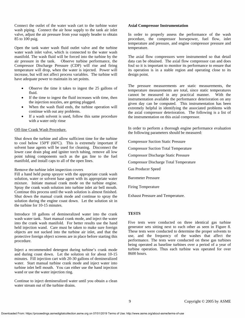
Gas Producer Speed Barometer Pressure Firing Temperature Exhaust Pressure and Temperature. TESTS Five tests were conducted on three identical gas turbine generator sets sitting next to each other as seen in Figure 8. These tests were conducted to determine the proper solvents to use, and the frequency of the washes that affect the performance. The tests were conducted on these gas turbines being operated as baseline turbines over a period of a year of turbine operation. Thus each turbine was operated for over 8600 hours.
9 Copyright © 2005 by ASME
se: http://www.asme.org/about-asme/terms-of-use
Dow
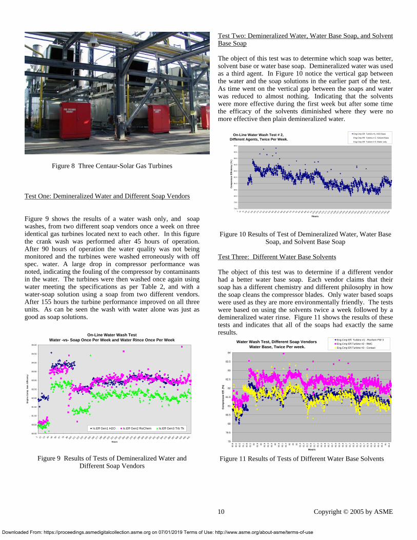
Figure 8 Three Centaur-Solar Gas Turbines Test One: Demineralized Water and Different Soap Vendors
Figure 9 shows the results of a water wash only, and soap washes, from two different soap vendors once a week on three identical gas turbines located next to each other. In this figure the crank wash was performed after 45 hours of operation. After 90 hours of operation the water quality was not being monitored and the turbines were washed erroneously with off spec. water. A large drop in compressor performance was noted, indicating the fouling of the compressor by contaminants in the water. The turbines were then washed once again using water meeting the specifications as per Table 2, and with a water-soap solution using a soap from two different vendors. After 155 hours the turbine performance improved on all three units. As can be seen the wash with water alone was just as good as soap solutions.
On-Line Water Wash Test Water -vs- Soap Once Per Week and Water Rince Once Per Week
80.00
80.50
81.00
81.50
82.00
82.50
83.00
83.50
84.00
84.50
85.00
1 12 23 34 45 56 67 78 89 100
111
122
133
144
155
166
177
188
199
210
221
232
243
254
265
276
287
298
309
320
331
342
353
364
375
386
397
408
419
430
441
Hours
Engi
ne C
omp.
Isen
. Effi
cenc
y
Is.Eff Gen1 H2O Is.Eff Gen2 RoChem Is.Eff Gen3 Trb Tk
Figure 9 Results of Tests of Demineralized Water and Different Soap Vendors
nloaded From: https://proceedings.asmedigitalcollection.asme.org on 07/01/2019 Terms of
Test Two: Demineralized Water, Water Base Soap, and Solvent Base Soap The object of this test was to determine which soap was better, solvent base or water base soap. Demineralized water was used as a third agent. In Figure 10 notice the vertical gap between the water and the soap solutions in the earlier part of the test. As time went on the vertical gap between the soaps and water was reduced to almost nothing. Indicating that the solvents were more effective during the first week but after some time the efficacy of the solvents diminished where they were no more effective then plain demineralized water.
On-Line Water Wash Test # 2, Different Agents, Twice Per Week.
79.0
79.5
80.0
80.5
81.0
81.5
82.0
82.5
83.0
83.5
84.0
1 40 79 118
157
196
235
274
313
352
391
430
469
508
547
586
625
664
703
742
781
820
859
898
937
976
1015
1054
1093
1132
1171
1210
1249
1288
1327
1366
1405
1444
1483
1522
1561
1600
1639
1678
1717
1756
1795
1834
1873
1912
1951
1990
Hours
Com
pres
sor E
ffici
ency
( %
)
Eng.Cmp Eff. Turbine #1, H2O Base
Eng.Cmp Eff. Turbine # 2, Solvent Base
Eng.Cmp Eff. Turbine # 3, Water only.
Figure 10 Results of Test of Demineralized Water, Water Base Soap, and Solvent Base Soap
Test Three: Different Water Base Solvents The object of this test was to determine if a different vendor had a better water base soap. Each vendor claims that their soap has a different chemistry and different philosophy in how the soap cleans the compressor blades. Only water based soaps were used as they are more environmentally friendly. The tests were based on using the solvents twice a week followed by a demineralized water rinse. Figure 11 shows the results of these tests and indicates that all of the soaps had exactly the same results.
Water Wash Test, Different Soap Vendors Water Base, Twice Per week.
79
79.5
80
80.5
81
81.5
82
82.5
83
83.5
84
80.8
80.2
80.5
81.1
80.8
82.2 82
81.8 82
81.8
81.5
81.5 82
81.6
81.1
81.4 82 82 82
81.9
81.4
82.2
81.6
81.7
81.4
81.4
81.8
81.7
81.7
81.5
81.5
81.9
81.7
81.7
81.6
81.4
81.4
81.7
81.5
81.6
82.4
81.4
81.3 81
81.2
Hours
Com
pres
sor E
ff. (%
)
Eng.Cmp Eff. Turbine #1 - Rochem FW 3Eng.Cmp Eff.Turbine #2 - RMCEng.Cmp Eff.Turbine #3 - Contact
Figure 11 Results of Tests of Different Water Base Solvents
10 Copyright © 2005 by ASME
Use: http://www.asme.org/about-asme/terms-of-use
Downlo
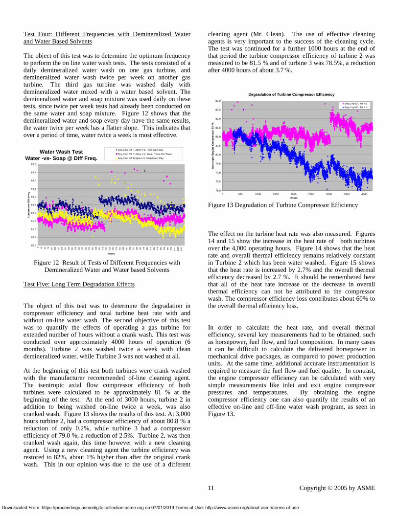
Test Four: Different Frequencies with Demineralized Water and Water Based Solvents The object of this test was to determine the optimum frequency to perform the on line water wash tests. The tests consisted of a daily demineralized water wash on one gas turbine, and demineralized water wash twice per week on another gas turbine. The third gas turbine was washed daily with demineralized water mixed with a water based solvent. The demineralized water and soap mixture was used daily on these tests, since twice per week tests had already been conducted on the same water and soap mixture. Figure 12 shows that the demineralized water and soap every day have the same results, the water twice per week has a flatter slope. This indicates that over a period of time, water twice a week is most effective.
Water Wash Test Water -vs- Soap @ Diff Freq.
80.0
80.5
81.0
81.5
82.0
82.5
83.0
83.5
84.0
84.5
85.0
1 26 51 76 101
126
151
176
201
226
251
276
301
326
351
376
401
426
451
476
501
526
551
576
601
626
651
676
701
726
751
776
801
826
851
876
901
926
951
976
1001
1026
1051
Hours
Com
pres
sor E
ficie
ncy
Eng.Cmp Eff. Turbine # 1, H2O every day.
Eng.Cmp Eff. Turbine # 2, Water Twice Per Week
Eng.Cmp Eff. Engine # 3, Soap Every Day.
Figure 12 Result of Tests of Different Frequencies with
Demineralized Water and Water based Solvents Test Five: Long Term Degradation Effects The object of this teat was to determine the degradation in compressor efficiency and total turbine heat rate with and without on-line water wash. The second objective of this test was to quantify the effects of operating a gas turbine for extended number of hours without a crank wash. This test was conducted over approximately 4000 hours of operation (6 months). Turbine 2 was washed twice a week with clean demineralized water, while Turbine 3 was not washed at all. At the beginning of this test both turbines were crank washed with the manufacturer recommended of-line cleaning agent. The isentropic axial flow compressor efficiency of both turbines were calculated to be approximately 81 % at the beginning of the test. At the end of 3000 hours, turbine 2 in addition to being washed on-line twice a week, was also cranked wash. Figure 13 shows the results of this test. At 3,000 hours turbine 2, had a compressor efficiency of about 80.8 % a reduction of only 0.2%, while turbine 3 had a compressor efficiency of 79.0 %, a reduction of 2.5%. Turbine 2, was then cranked wash again, this time however with a new cleaning agent. Using a new cleaning agent the turbine efficiency was restored to 82%, about 1% higher than after the original crank wash. This in our opinion was due to the use of a different
aded From: https://proceedings.asmedigitalcollection.asme.org on 07/01/2019 Terms of Use
cleaning agent (Mr. Clean). The use of effective cleaning agents is very important to the success of the cleaning cycle. The test was continued for a further 1000 hours at the end of that period the turbine compressor efficiency of turbine 2 was measured to be 81.5 % and of turbine 3 was 78.5%, a reduction after 4000 hours of about 3.7 %.
Degradation of Turbine Compressor Efficiency
78.0
78.5
79.0
79.5
80.0
80.5
81.0
81.5
82.0
82.5
83.0
0 500 1000 1500 2000 2500 3000 3500 4000Hours
Isen
trop
ic E
ngin
e C
ompr
esso
r Eff
%
Eng.Cmp Eff. Trb #2Eng.Cmp Eff. Trb # 3
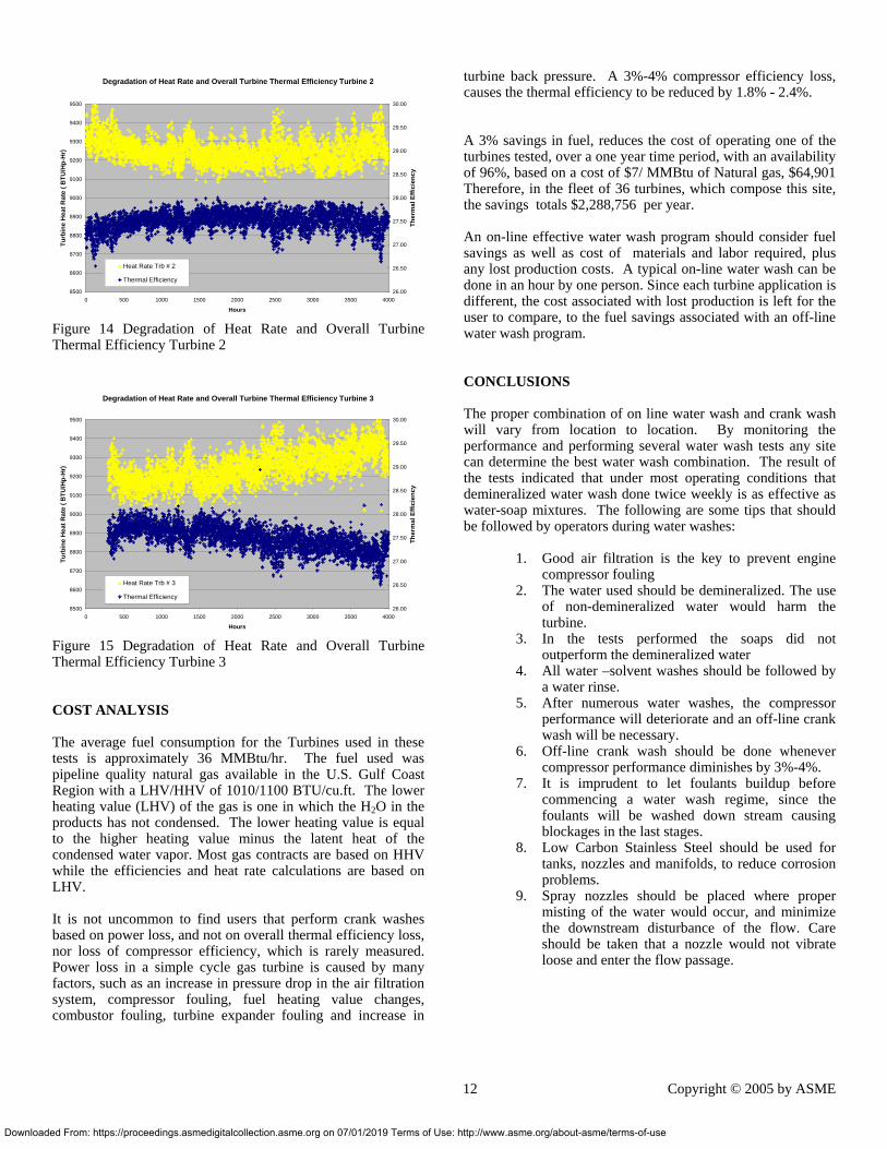
Figure 13 Degradation of Turbine Compressor Efficiency The effect on the turbine heat rate was also measured. Figures 14 and 15 show the increase in the heat rate of both turbines over the 4,000 operating hours. Figure 14 shows that the heat rate and overall thermal efficiency remains relatively constant in Turbine 2 which has been water washed. Figure 15 shows that the heat rate is increased by 2.7% and the overall thermal efficiency decreased by 2.7 %. It should be remembered here that all of the heat rate increase or the decrease in overall thermal efficiency can not be attributed to the compressor wash. The compressor efficiency loss contributes about 60% to the overall thermal efficiency loss. In order to calculate the heat rate, and overall thermal efficiency, several key measurements had to be obtained, such as horsepower, fuel flow, and fuel composition. In many cases it can be difficult to calculate the delivered horsepower in mechanical drive packages, as compared to power production units. At the same time, additional accurate instrumentation is required to measure the fuel flow and fuel quality. In contrast, the engine compressor efficiency can be calculated with very simple measurements like inlet and exit engine compressor pressures and temperatures. By obtaining the engine compressor efficiency one can also quantify the results of an effective on-line and off-line water wash program, as seen in Figure 13.
11 Copyright © 2005 by ASME
: http://www.asme.org/about-asme/terms-of-use
Dow
Degradation of Heat Rate and Overall Turbine Thermal Efficiency Turbine 2
8500
8600
8700
8800
8900
9000
9100
9200
9300
9400
9500
0 500 1000 1500 2000 2500 3000 3500 4000
Hours
Turb
ine
Hea
t Rat
e ( B
TU/H
p-H
r)
26.00
26.50
27.00
27.50
28.00
28.50
29.00
29.50
30.00
Ther
mal
Effi
cien
cy
Heat Rate Trb # 2
Thermal Efficiency
Figure 14 Degradation of Heat Rate and Overall Turbine Thermal Efficiency Turbine 2
Degradation of Heat Rate and Overall Turbine Thermal Efficiency Turbine 3
8500
8600
8700
8800
8900
9000
9100
9200
9300
9400
9500
0 500 1000 1500 2000 2500 3000 3500 4000
Hours
Turb
ine
Hea
t Rat
e ( B
TU/H
p-H
r)
26.00
26.50
27.00
27.50
28.00
28.50
29.00
29.50
30.00Th
erm
al E
ffici
ency
Heat Rate Trb # 3
Thermal Efficiency
Figure 15 Degradation of Heat Rate and Overall Turbine Thermal Efficiency Turbine 3 COST ANALYSIS The average fuel consumption for the Turbines used in these tests is approximately 36 MMBtu/hr. The fuel used was pipeline quality natural gas available in the U.S. Gulf Coast Region with a LHV/HHV of 1010/1100 BTU/cu.ft. The lower heating value (LHV) of the gas is one in which the H2O in the products has not condensed. The lower heating value is equal to the higher heating value minus the latent heat of the condensed water vapor. Most gas contracts are based on HHV while the efficiencies and heat rate calculations are based on LHV. It is not uncommon to find users that perform crank washes based on power loss, and not on overall thermal efficiency loss, nor loss of compressor efficiency, which is rarely measured. Power loss in a simple cycle gas turbine is caused by many factors, such as an increase in pressure drop in the air filtration system, compressor fouling, fuel heating value changes, combustor fouling, turbine expander fouling and increase in
nloaded From: https://proceedings.asmedigitalcollection.asme.org on 07/01/2019 Terms of Us
turbine back pressure. A 3%-4% compressor efficiency loss, causes the thermal efficiency to be reduced by 1.8% - 2.4%. A 3% savings in fuel, reduces the cost of operating one of the turbines tested, over a one year time period, with an availability of 96%, based on a cost of $7/ MMBtu of Natural gas, $64,901 Therefore, in the fleet of 36 turbines, which compose this site, the savings totals $2,288,756 per year. An on-line effective water wash program should consider fuel savings as well as cost of materials and labor required, plus any lost production costs. A typical on-line water wash can be done in an hour by one person. Since each turbine application is different, the cost associated with lost production is left for the user to compare, to the fuel savings associated with an off-line water wash program. CONCLUSIONS The proper combination of on line water wash and crank wash will vary from location to location. By monitoring the performance and performing several water wash tests any site can determine the best water wash combination. The result of the tests indicated that under most operating conditions that demineralized water wash done twice weekly is as effective as water-soap mixtures. The following are some tips that should be followed by operators during water washes:
1. Good air filtration is the key to prevent engine compressor fouling
2. The water used should be demineralized. The use of non-demineralized water would harm the turbine.
3. In the tests performed the soaps did not outperform the demineralized water
4. All water –solvent washes should be followed by a water rinse.
5. After numerous water washes, the compressor performance will deteriorate and an off-line crank wash will be necessary.
6. Off-line crank wash should be done whenever compressor performance diminishes by 3%-4%.
7. It is imprudent to let foulants buildup before commencing a water wash regime, since the foulants will be washed down stream causing blockages in the last stages.
8. Low Carbon Stainless Steel should be used for tanks, nozzles and manifolds, to reduce corrosion problems.
9. Spray nozzles should be placed where proper misting of the water would occur, and minimize the downstream disturbance of the flow. Care should be taken that a nozzle would not vibrate loose and enter the flow passage.
12 Copyright © 2005 by ASME
e: http://www.asme.org/about-asme/terms-of-use
Dow
REFERENCES:
1. “Condition Monitoring and Its Effect on the Life of New Advanced Gas Turbines”, Boyce and Latcovich, Gas Turbine Users Association Conference, Houston, Texas, April 21-25, 2002
2. “Gas Turbine Engineering Handbook”-Meherwan P.
Boyce, P.HD., P.E., Second Edition, Butterworth-Hienemann-January 2003
3. “Handbook for Cogeneration and Combined Cycle
Power Plants” Meherwan P. Boyce, P.HD., P.E. ASME February 2003
13 Copyright © 2005 by ASME
nloaded From: https://proceedings.asmedigitalcollection.asme.org on 07/01/2019 Terms of Use: http://www.asme.org/about-asme/terms-of-use
Related Documents