University of South Florida University of South Florida Digital Commons @ University of South Florida Digital Commons @ University of South Florida Graduate Theses and Dissertations Graduate School 10-26-2010 A Study of Omnidirectional Quad-Screw-Drive Configurations for A Study of Omnidirectional Quad-Screw-Drive Configurations for All-Terrain Locomotion All-Terrain Locomotion Jon T. Freeberg University of South Florida Follow this and additional works at: https://digitalcommons.usf.edu/etd Part of the American Studies Commons Scholar Commons Citation Scholar Commons Citation Freeberg, Jon T., "A Study of Omnidirectional Quad-Screw-Drive Configurations for All-Terrain Locomotion" (2010). Graduate Theses and Dissertations. https://digitalcommons.usf.edu/etd/3550 This Thesis is brought to you for free and open access by the Graduate School at Digital Commons @ University of South Florida. It has been accepted for inclusion in Graduate Theses and Dissertations by an authorized administrator of Digital Commons @ University of South Florida. For more information, please contact [email protected].

Welcome message from author
This document is posted to help you gain knowledge. Please leave a comment to let me know what you think about it! Share it to your friends and learn new things together.
Transcript

University of South Florida University of South Florida
Digital Commons @ University of South Florida Digital Commons @ University of South Florida
Graduate Theses and Dissertations Graduate School
10-26-2010
A Study of Omnidirectional Quad-Screw-Drive Configurations for A Study of Omnidirectional Quad-Screw-Drive Configurations for
All-Terrain Locomotion All-Terrain Locomotion
Jon T. Freeberg University of South Florida
Follow this and additional works at: https://digitalcommons.usf.edu/etd
Part of the American Studies Commons
Scholar Commons Citation Scholar Commons Citation Freeberg, Jon T., "A Study of Omnidirectional Quad-Screw-Drive Configurations for All-Terrain Locomotion" (2010). Graduate Theses and Dissertations. https://digitalcommons.usf.edu/etd/3550
This Thesis is brought to you for free and open access by the Graduate School at Digital Commons @ University of South Florida. It has been accepted for inclusion in Graduate Theses and Dissertations by an authorized administrator of Digital Commons @ University of South Florida. For more information, please contact [email protected].

A Study of Omnidirectional Quad-Screw-Drive Configurations for
All-Terrain Locomotion
by
Jon T. Freeberg
A thesis submitted in partial fulfillment of the requirements for the degree of
Master of Science in Mechanical Engineering Department of Mechanical Engineering
College of Engineering University of South Florida
Major Professor: Stuart Wilkinson, Ph.D. Craig Lusk, Ph.D. Kyle Reed, Ph.D.
Date of Approval: October 26, 2010
Keywords: Amphibious, Submarine, Robot, Trafficability, Dynamics
Copyright © 2010 Jon T. Freeberg
i
TABLE OF CONTENTS
LIST OF TABLES iv LIST OF FIGURES v NOMENCLATURE ix ABSTRACT x CHAPTER 1: BACKGROUND 1 1.1 Fundamentals 1 1.2 History of Screw-Vehicles 3 1.3 Applications 5 CHAPTER 2: PREVIOUS RESEARCH 8 2.1 Important Studies 8 2.2 Screw Design Parameters 11 2.2.1 Helix-Angle 12 2.2.2 Blade-Height-to-Drum-Diameter Ratio 12 2.2.3 Number of Starts 13 2.2.4 Length-to-Drum-Diameter Ratio 13 2.2.5 Blade-Thickness 14 2.2.6 Center of Gravity 15 2.3 Trafficability Tests 16 2.3.1 Sand 17 2.3.2 Fine-Grained Soil 18 2.3.3 Snow 20 2.3.4 Water 20 2.3.5 Trafficability Tests Summary 21 CHAPTER 3: THE DOUBLE-SCREW 23 3.1 Capabilities 23 3.1.1 Counter-Rotating Screws 25 3.1.2 Co-Rotating Screws 26 3.1.3 Turning 27 3.2 Limitations 31 CHAPTER 4: ALTERNATIVE SCREW CONFIGURATIONS 34 4.1 Overview 34 4.2 Bendable-Screw 34

ii
4.3 Split-Screw 36 4.4 Inline-Screw 39 4.5 Cross-Screw and Diamond-Screw 44 CHAPTER 5: THE TERRAIN TWISTER 48 5.1 Description 48 5.2 Test-Bed Construction 49 5.3 Test Comparison 51 CHAPTER 6: QUAD-SCREW TEST-BED CONSTRUCTION 52 6.1 Test-Bed Frame 52 6.2 Screw-Assemblies 56 6.3 Wiring and Controls 57 6.4 Modifications 60 CHAPTER 7: EXPERIMENTS 64 7.1 Experimental Goals 64 7.2 Methodology 65 7.2.1 Test Locations 65 7.2.2 Testing Directions 67 7.2.3 Test Setup 68 7.3 Test Observations 69 7.3.1 Grass 69 7.3.2 Dirt 71 7.3.3 Marsh 73 7.3.4 Sand 74 7.3.5 Clay 76 7.3.6 Pavement 78 7.3.7 Gravel 81 7.3.8 Surface of Water 83 7.3.9 Underwater 85 7.3.10 Snow 87 7.3.11 Split-Screw Tests 88 7.4 Turning Radius 89 7.5 Test Summary 92 CHAPTER 8: CONCLUSIONS 99 LIST OF REFERENCES 101 BIBLIOGRAPHY 103 APPENDICES 105 Appendix A: S-Diamond-Screw Force-Vectors 106 Appendix B: S-Cross-Screw Force-Vectors 107 Appendix C: Mirrored Test-Bed Force-Vectors 108 Appendix D: Terrain Twister Screw Calculations 111

iii
ABOUT THE AUTHOR END PAGE

iv
LIST OF TABLES Table 1: Terrain Twister screw geometry 50 Table 2: Turning-diameter and turning-ratio in marsh 90 Table 3: Quad-screw performance matrix 92 Table 4: Double-screw performance matrix 94 Table A1: Terrain Twister screw measurements 111

v
LIST OF FIGURES Figure 1: Riverine Utility Craft’s (RUC) speed versus terrain firmness 3 Figure 2: The Fordson Snowmobile 4 Figure 3: A snake-like screw robot 5 Figure 4: The Snowbird 6 7 Figure 5: Dr. B.N. Cole working with a model screw-vehicle 9 Figure 6: The Marsh Screw Amphibian 10 Figure 7: An illustration of important screw parameters 11 Figure 8: The RUC’s blade support 14 Figure 9: The RUC’s center of gravity 15 Figure 10: A cone penetrometer 17 Figure 11: The MSA buried on pass 36 19 Figure 12: The RUC performing a mine sweep test 21 Figure 13: Rolling- and tractive-forces imparted on screws by a soft
terrain 24 Figure 14: Screws counter-rotating on different surfaces 26 Figure 15: Screws co-rotating in different terrains 27 Figure 16: Screws skid-turning on soft ground 28 Figure 17: The turning radius of hinged-screws 30 Figure 18: The minimum turning radius for hinged-screws 30 Figure 19: An example of hinged-screws 33

vi
Figure 20: Red and blue halves experiencing alternating tension 35 Figure 21: Modes of rotation for a bendable-screw 36 Figure 22: Top view of the split-screw layout 37 Figure 23: Four symmetric screw rotations for the split-screw 38 Figure 24: A top view of the inline-screw 39 Figure 25: The turning radius of an inline-screw 40 Figure 26: The turning radius of an inline-screw superimposed on a
hinged screw’s turning radius 41 Figure 27: Four symmetric screw rotations for the inline-screw 42 Figure 28: Reversing the direction of rotation for each symmetric
switch pattern results in the opposite direction of locomotion 43
Figure 29: Model of the inline-screw 44 Figure 30: Models of the cross-screw and diamond-screw 44 Figure 31: The patented cross-screw and diamond-screw
configurations 46 Figure 32: Four symmetric screw rotations for the diamond-screw 46 Figure 33: Four symmetric screw rotations for the cross-screw 47 Figure 34: The Terrain Twister screw-assembly 49 Figure 35: Right plane, test-bed model 53 Figure 36: A PVC end-cap with the spring for battery contact 54 Figure 37: Front plane, test-bed model 55 Figure 38: Trimetric, test-bed model 55 Figure 39: A photograph of the test-bed 56 Figure 40: The barrier strip wiring 58 Figure 41: The switchbox wiring 59

vii
Figure 42: Switch patterns for forward, right and clockwise locomotion 60 Figure 43: The author shown alongside the test-bed 61 Figure 44: The floating test-bed setup 62 Figure 45: The inflatable tube used to suspend the test-bed 63 Figure 46: An example of the test setup 68 Figure 47: Test setup for grass terrain 70 Figure 48: Tracks from the inline-screw deviating in dirt 72 Figure 49: Tracks in marsh left by the inline-screw 73 Figure 50: Sand terrain test setup 75 Figure 51: The test setup for clay terrain 76 Figure 52: Inline-screw tracks in clay 77 Figure 53: Diamond-screw rotation tracks in clay 78 Figure 54: The cross-screw on pavement 79 Figure 55: Inline-screw performance with minimal tractive-force
influence such as on pavement 80 Figure 56: Test setup for gravel terrain 81 Figure 57: Path from the diamond-screw rotating in gravel 82 Figure 58: Test setup for the surface of water 84 Figure 59: Inline-screw performance with minimal rolling-force
influence such as on water 85 Figure 60: Underwater view during testing 86 Figure 61: Test setup for underwater testing 86 Figure 62: The test course for snow 87 Figure 63: The plan and turning diameter 89 Figure 64: The double-screw’s rotation tracks left in marsh 91

viii
Figure 65: Test-bed rotation tracks left in marsh 91 Figure 66: A graph illustrating the correlation between forward speed
and percent slip 95 Figure 67: Longitudinal speeds for the test-bed configurations in
different terrains 96 Figure 68: The test-bed setup for the cross-screw and diamond-screw
in water 97 Figure 69: Lateral speeds for the test-bed configurations in different
terrains 97 Figure 70: Rotational speeds for the test-bed configurations in
different terrains 98 Figure A1: Four symmetric screw rotations for the S-diamond-screw 106 Figure B1: Four symmetric screw rotations for the S-cross-screw 107 Figure C1: Four symmetric screw rotations for the mirrored inline-
screw 108 Figure C2: Four symmetric screw rotations for the mirrored-diamond-
screw 109 Figure C3: Four symmetric screw rotations for the mirrored-cross-
screw 110 Figure D1: The Terrain Twister’s major diameter and lead 112

ix
NOMENCLATURE Symbol Description Units c Center-to-center of screws in h Blade-height in l Drum-length in r Turning radius in D Drum-diameter in Dm Screw’s major-diameter in L Screw’s lead in N Number of blade revolutions non-dimensional T Travel distance ft θ Hinge-angle o Φ Helix-angle o
Acronyms Description C.G. Center of gravity MSA Marsh Screw Amphibian RCI Rating cone index RUC Riverine Utility Craft VCI Vehicle cone index

x
A STUDY OF OMNIDIRECTIONAL QUAD-SCREW-DRIVE
CONFIGURATIONS FOR ALL-TERRAIN LOCOMOTION
JON T. FREEBERG
ABSTRACT
Double-screw vehicles have been developed to operate in soft, wet
terrains such as marsh, snow, and water. Their exceptional performance in
soft and wet terrains is at the expense of performance on rigid terrains such
as pavement. Furthermore, turning can be difficult because the method of
turning varies depending on the terrain. Therefore, in this study, several
different quad-screw-configurations were proposed and tested to improve
upon double-screw vehicles.
A test-bed was developed which could easily be converted into each
quad-screw-configuration for testing on a variety of surfaces (grass, dirt,
sand, clay, marsh, snow, gravel, pavement, and water). In addition, a force-
vector analysis was performed for each screw-configuration to predict and
understand performance in different terrains.
From the testing and analysis, the inline-screw configuration was the
most versatile because it was omnidirectional on all surfaces but water and
pavement. Regardless, it was fully capable of navigating water, both on the
surface and submerged, and pavement by rotating about its center.

1
CHAPTER 1: BACKGROUND
1.1 Fundamentals
Wheeled and tracked vehicles are a proven and effective means of
locomotion for a wide range of surfaces. Nonetheless, there are conditions in
which both means of locomotion have shortcomings. For instance, both
vehicles encounter difficulty with marshy environments in which the ground’s
bearing strength is minimal. In such extreme off-road environments, it can
be nearly impossible to prevent the vehicle from sinking and becoming
immobilized.
In order to understand the degree of effectiveness a wheeled or
tracked vehicle will display on a given surface, it is important to understand
how it works. Note that while they may have dissimilar performance on a
given surface, the underlying principle they use to provide locomotion is the
same. “Conventional wheeled and tracked vehicles depend upon soil bearing
strength for support, and on frictional and cohesive soil shear strength for
propulsion.” [1]
Clearly, most wheels and tracks provide negligible buoyancy to a
vehicle, as is evident in a vehicle sinking in water or a soil of high moisture
content. Furthermore, spinning tires on a slippery road demonstrate a wheel

2
or track’s frictional requirement. Finally, wheels that are digging a hole in
loose sand underscore the need for cohesive soil shear strength.
A novel locomotion concept, which may resolve the shortcomings of
wheeled and tracked vehicles, consists of two counter-rotating, buoyant
screws. The buoyant screw relies on completely different principles for
locomotion as compared to a wheeled or tracked vehicle.
“[…] the support function is fulfilled by buoyant flotation, rather than by intrinsic soil strength. Propulsion is accomplished by viscous shear and reaction to mass movement of the medium, rather than by friction and cohesion in the soil mass.” [1]
Since the screw provides buoyant flotation, its application extends
beyond surfaces of great moisture content to the surface of water itself.
However, since the locomotion is generated by mass movement of a
medium, it is restricted to non-rigid surfaces. On a solid and rigid surface,
such as pavement, the blades rest on the surface and, in turn, operate on
the same principle of locomotion as a wheel or track; an exception is ice in
which a metal screw is able to carve into it. Though no specific studies were
available regarding the mechanism for how a screw-vehicle works on ice, it
has been shown to work. It can be surmised that screw-vehicles operate
much like an ice skater digging into the ice.
Considering the nature of each locomotion system, it is understandable
that the performances of screw-vehicles are nearly the opposite of wheeled
and tracked vehicles for different surfaces [1]. Figure 1 shows the speed of
the Riverine Utility Craft screw-vehicle. The Riverine Utility Craft, or RUC, is a
full-scale double-screw military test-bed vehicle. It shows screw-vehicles

3
operate in water and on soil, but are optimal where conventional vehicles are
not.
Figure 1: Riverine Utility Craft’s (RUC) speed versus terrain firmness [2].
Note: all values are in generic units.
1.2 History of Screw-Vehicles
• 1804: A screw-steamboat is driven by Colonel John Stevens on New
York’s North River [3].
• 1841: Thomas J Wells patents the “buoyant spiral propeller” in which
the screw provides buoyancy to the vessel [1].
• Late 1920’s: The Fordson snowmobile is built; demonstrating snow
and ice performance [3].

4
Figure 2: The Fordson Snowmobile [4].
• 1948: An amphibious screw-tractor is proposed in England by Lt. Col.
H.O. Nelson [3].
• Early 1950’s: A M29C Weasel tank is outfitted with screws to replace
treads and is tested in Greenland by the US army [3].
• 1957: A German firm demonstrates a screw-amphibian at the Hanover
exhibition [3].
• 1960’s: The Russians develop a screw-tank to pick up and drop off
cosmonauts in heavy snow [5].
• 1966: A patent for a marsh screw-vehicle is awarded to R.G. Schrader
[3].
• 2001: The Snowbird 5 fails to cross the Bering Strait due to damage to
its pontoon [5].
• 2002: The Snowbird 6 is developed and successfully crosses the Bering
Strait [5].
• 2005: The Tyco® Terrain Twister toy is patented [6].
• 2007: A snake-like, screw-robot is researched [7].
5
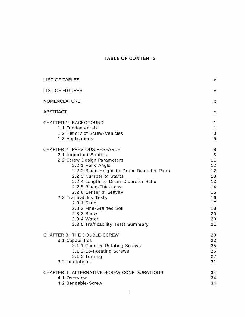
Figure 3: A snake-like screw-robot [7].
1.3 Applications
As discussed in section 1.1, screw-vehicles fill an important gap in
vehicle performance between the terrain-navigating capabilities of boats and
standard wheeled and tracked vehicles. Specifically, in shallow, marshy
environments, boats risk damaging the propeller or becoming grounded,
while wheeled and tracked vehicles perform poorly in saturated ground.
Conversely, a screw-vehicle performs best in marshy environments [7, 8].
Another terrain condition not discussed is snowy ground. Screw-
vehicles perform well in deep, powdery snow. On the contrary, a boat will
not operate in snow, while wheeled and tracked vehicles must be specialized
for snow in order to perform well. Therefore, a vehicle that must cross
marshy or snowy surfaces would benefit from screw locomotion.
An important advantage of a screw-vehicle is its capability of
traversing a wide range of environments without altering the vehicle.
Amphibious cars and tanks have been developed, but they typically require a
6
transformation of their locomotion method or vehicle body to go from land to
water. In contrast, a buoyant screw can provide flotation and it propels the
vehicle aground and afloat. All in all, a screw-vehicle can operate on the
ocean floor, on top of water, submerged and above the ocean floor, in
marshes, snow, sand, dirt, grass, ice, and, to a limited extent, pavement.
Some examples of screw-vehicles that have been built in the past
include:
• MudMaster (2009): The MudMaster was used for bauxite residue
production in the alumina refining industry. It was useful for the
alumina industry due to the screw-vehicle’s effectiveness in mud and
wet clay [10].
• Basin cleaning vehicle (BCV) (1999): The BCV was developed to crawl
along lakebeds to remove sediment. Lakebed sediment impedes the
percolation process that provides natural filtration to water supplies
[11].
• Icy-water, oil-recovery vehicle (1996): An oil-recovery vehicle concept
was considered by Sintef. The concept used screws to deflect ice and
help collect spilled oil. The device was proposed to operate similar to a
drum skimmer [12].
• Snowbird 6 (2002): The Snowbird 6 vehicle crossed snowy, Alaskan
terrain and the Bering Strait using two counter-rotating screws [5].

7
Figure 4: The Snowbird 6 [5].
• Spiral Track Autonomous Robot (STAR) (1996): The STAR was a
screw-robot designed for hostile terrain. Specifically, it was designed
for American police and military personnel [13].
• Terrain Twister (2005): The Terrain Twister was a toy which used
screws to go over terrains that most toys would not; including snow
and water.

8
CHAPTER 2: PREVIOUS RESEARCH
2.1 Important Studies
The concept of a screw-vehicle dates back as early as the 1800’s [3]
with the screw-steamboat, and in the 1920’s it was first used on land with
the Fordson snow tractor [9]. More recently, screw-vehicles have seen niche
applications, including the Snowbird 6 used to cross the Bering Strait. [5].
However, the 1960’s was the period in which much of the rigorous research
regarding screw-vehicles was performed. Specifically, in the 1960’s screw
design parameters were developed and screw-vehicle trafficability studies
were performed.
In 1961, a pilot study on screw design was published in England by Dr.
B.N Cole [14] and it serves to be an important technical report concerning
amphibious screw-vehicles. Within Dr. Cole’s report is a theoretical
investigation of screw design parameters such as the blade’s helix-angle and
the screw’s overall length. His research was for operation in and out of
water. In supplement to the theoretical modeling, a scale model was built to
compare six sets of left- and right-handed screws. These screws were used
to reveal how actual data compared with his theoretical calculations. The
sets of screws consisted of three 13-inch short screws and three 22.3-inch
9
long screws. Each group of long and short screws consisted of one set of
20o-, 30o- and 40o- helix-angles.
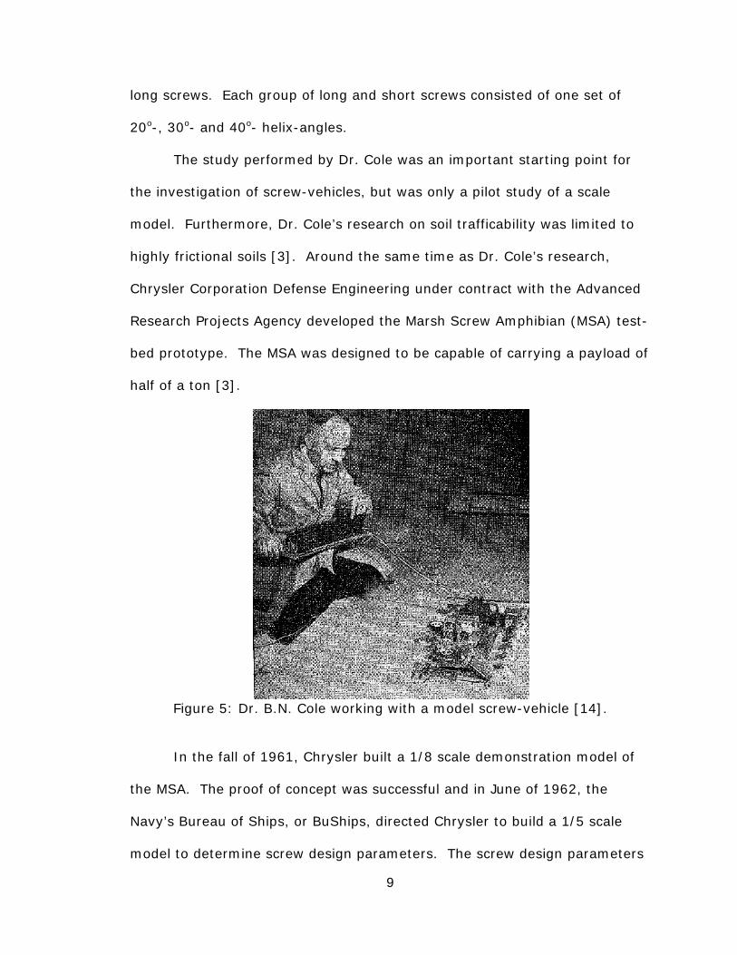
The study performed by Dr. Cole was an important starting point for
the investigation of screw-vehicles, but was only a pilot study of a scale
model. Furthermore, Dr. Cole’s research on soil trafficability was limited to
highly frictional soils [3]. Around the same time as Dr. Cole’s research,
Chrysler Corporation Defense Engineering under contract with the Advanced
Research Projects Agency developed the Marsh Screw Amphibian (MSA) test-
bed prototype. The MSA was designed to be capable of carrying a payload of
half of a ton [3].
Figure 5: Dr. B.N. Cole working with a model screw-vehicle [14].
In the fall of 1961, Chrysler built a 1/8 scale demonstration model of
the MSA. The proof of concept was successful and in June of 1962, the
Navy’s Bureau of Ships, or BuShips, directed Chrysler to build a 1/5 scale
model to determine screw design parameters. The screw design parameters
10
considered were the optimum length-to-diameter ratio, the height of the
screw blade, the blade’s helix-angle, and if 1-, 2- or 4-starts should be used.
In addition, horsepower requirements and the screw’s slip were investigated
on land and water [15].
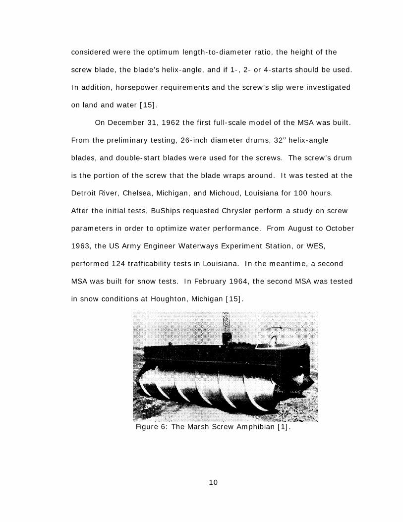
On December 31, 1962 the first full-scale model of the MSA was built.
From the preliminary testing, 26-inch diameter drums, 32o helix-angle
blades, and double-start blades were used for the screws. The screw’s drum
is the portion of the screw that the blade wraps around. It was tested at the
Detroit River, Chelsea, Michigan, and Michoud, Louisiana for 100 hours.
After the initial tests, BuShips requested Chrysler perform a study on screw
parameters in order to optimize water performance. From August to October
1963, the US Army Engineer Waterways Experiment Station, or WES,
performed 124 trafficability tests in Louisiana. In the meantime, a second
MSA was built for snow tests. In February 1964, the second MSA was tested
in snow conditions at Houghton, Michigan [15].
Figure 6: The Marsh Screw Amphibian [1].

11
The studies on the MSA provided much of the information regarding
screw parameters and terrain trafficability used in this thesis. In addition, its
success led to the development of another screw-vehicle program aimed at
developing a finalized and practical vehicle. On July 25 1969, the Naval Ship
Systems Command requested the US Army Engineer Waterways Experiment
Station, or WES, to test Riverine Utility Crafts, or RUCs [9]. Similar to the
MSAs, the studies on the RUCs were useful in this thesis.
2.2 Screw Design Parameters
There are several parameters to consider for a screw design. Some
considerations for the screw’s blade are its helix-angle, height, and number
of starts. Furthermore, considerations for the screw-drum include its length
and diameter. Each of the above parameters have been previously
researched in the studies outlined in section 2.1 and are documented in this
section.
Figure 7: An illustration of important screw parameters.
12
2.2.1 Helix-Angle. Dr. Cole performed tests on screws comparing
helix-angles. The helix-angles tested were 20o, 30o and 40o and tests were
conducted aground and afloat. Chrysler also compared the helix-angle of the
blades; including, 30o, 40o and 50o. From Dr. Cole’s ground experiments, 20o
drew the most power from the screw’s motors and created the greatest
amount of ground deformation [14]. One benefit of the 20o screw was that it
had the best drawbar-pull capability. Drawbar-pull is a test used to
determine the ratio of weight an off-road vehicle can tow in comparison to its
own weight. In contrast to the 20o screws, the 40o screws required the least
power but had the greatest amount of slippage [14].
The results of Dr. Cole’s hydrodynamic experiments show that the
greater the helix-angle, the greater the axial thrust and driving torque
developed [14]. They also show that the propulsive efficiency is maximized
at 30o. Furthermore, referring back to the ground experiments, it is shown
that the vehicle performance gap, as determined by the screw’s slippage and
power usage, is less between 30o to 40o than it is between 20o to 30o[14]. In
addition, the drawbar-pull is nearly maximized at 30o, with minimal
improvement as the helix-angle decreases [3]. Therefore, combining the
results of the aground and afloat tests, the optimum helix-angle is 30o or
slightly larger. In fact, the helix-angle chosen for the RUC was 32o [15].
2.2.2 Blade-Height-to-Drum-Diameter Ratio. In all of Dr. Cole’s
tests, a blade-height-to-drum-diameter ratio of 0.375 was used. He
concluded that, from the perspective of propulsive surface area and
structural strength of the blades, a ratio of 0.375 was adequate [14]. The

13
tests performed by Chrysler included ratios of 0.125, 0.167 and 0.208 [3].
The experiments show that increasing the blade’s height increases the weight
of the failure surface in sand. The increased weight of the failure surface
increases the drawbar-pull, but the effect is minimal [3]. Chrysler tested
blade-height in muddy conditions and found that increasing the height
reduced effectiveness of the vehicle. In particular, the increased blade-
height captured more mud and resulted in greater motion resistance [3].
Overall, based off of the blade-height-to-drum-diameter ratios tested, 0.125
is the ideal ratio.
2.2.3 Number of Starts. Not much information is available
regarding the impact of the number of starts for a screw-vehicle.
Nonetheless, Chrysler did perform a study to determine the ideal number of
starts. Though the study details were not available, it is apparent that two
starts is optimal. The RUC and MSA vehicles each have a design in which
there are two starts per screw [8, 14]. Furthermore, Dr. Cole mentions in
his research that two starts would be more dynamically balanced than one
[14].
2.2.4 Length-to-Drum-Diameter Ratio. The length-to-drum-
diameter ratio is an important parameter because it has the greatest
influence on the drawbar-pull capacity compared to the helix-angle or blade-
height [3]. Unlike the other parameters, the length-to-diameter ratio does
not have a monotonic trend of just increasing or decreasing performance as
the ratio increases or decreases [3]. Fortunately, when tests were
14
performed in mud and sand, it was determined the optimum ratio was 6 for
both mediums [3].
Another consideration is that increasing the length also increases the
number of revolutions of the blade. Dr. Cole theorized that increasing the
number of revolutions would have an impact on hydrodynamic driving torque
and thrust [14]. From his tests, Dr. Cole concluded that longer screws with
more rotations produce much larger driving torque and thrust [14].
2.2.5 Blade-Thickness. The performance due to the thickness of the
blades is not explicitly discussed in any available studies. The blades were
likely made thick enough to withstand the stresses imparted by the weight of
the vehicle and terrain interaction. Also, the material used plays an
important role in determining the required structural thickness. It is not
entirely evident if there is any importance from the standpoint of
performance, but there may be potential impact when on ice.
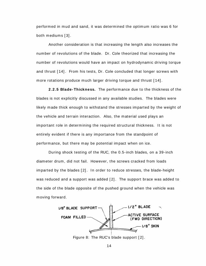
During shock testing of the RUC, the 0.5-inch blades, on a 39-inch
diameter drum, did not fail. However, the screws cracked from loads
imparted by the blades [2]. In order to reduce stresses, the blade-height
was reduced and a support was added [2]. The support brace was added to
the side of the blade opposite of the pushed ground when the vehicle was
moving forward.
Figure 8: The RUC’s blade support [2].

15
2.2.6 Center of Gravity. Although the location of the longitudinal
center of gravity, abbreviated as C.G., is not inherently a characteristic of the
screw, it is still worth mentioning for screw-vehicle design. Tests were
performed by Chrysler to determine the effects of the location of the C.G. by
placing the C.G. at four locations. The locations selected for the testing were
25% forward of the midpoint, at the midpoint, 12.5% aft of the midpoint,
and 25% aft of the midpoint [3].
Effectiveness of the C.G. location was determined by monitoring the
drawbar-pull capacity as the slip percentage increased. Typically, as slippage
increases, the drawbar-pull capacity increases [3]. However, in sand it was
shown that when the C.G. was at the front of the vehicle it began to plow
into the sand as slippage increased [3]. The final results show that the
vehicle operates best in sand with the C.G. at the midpoint or a little aft, and
when in mud it works best when the C.G. is at the midpoint [3]. Figure 9
shows that the C.G. is near the midpoint for the RUC.
Figure 9: The RUC’s center of gravity [9].
16
2.3 Trafficability Tests
In order to understand the performance of off-road vehicles, it is
important to perform trafficability tests. Trafficability tests are tests
performed in a uniform terrain that reveal vehicle-to-terrain behavior [9].
Tests may include maximum straight-line speed-tests, maximum maneuver
speed-tests, drawbar-pull tests, and repetitive pass, or vehicle cone index,
tests [9]. The tests performed on screw-vehicles were meant to determine
worst-case operating conditions. As a result, many of the tests resulted in
vehicle immobilization.
Maximum straight-line speed-tests and maximum maneuver-speed-
tests are exactly what their names imply. They test the fastest a vehicle can
possibly travel in a straight line or maneuver through an obstacle course.
Drawbar-pull tests are used to determine the ratio of weight an off-road
vehicle can tow in comparison to its own weight, and are among the best
tests for determining off-road vehicle performance [3]. Vehicle cone index,
or VCI, is a measure of the minimum rating cone index, or RCI, required for
a terrain to support a vehicle for a specified number of passes [9]. Typically,
50 passes are specified for the VCI test. The number of passes a VCI is
tested at is indicated with a subscript showing the number of passes.
Therefore, a 50 pass test is VCI50. The RCI is a measure of soil strength,
where a low RCI is a soft soil [9]. The value of RCI is found with a tool called
a penetrometer.

17
Figure 10: A cone penetrometer [9].
2.3.1 Sand. Sand is characterized by a high coefficient of friction and
minimal particle cohesion when dry [8]. From trafficability tests performed
on the MSA, it is evident that characteristics of sand work against screw-
vehicle performance. The RCI of the sand averaged at 95 and ranged from
46-159 during the testing, but it was determined that the impact of the RCI
was minimal in sand [8].
During repetitive pass tests, the MSA displayed difficulty driving
straight when unloaded. Furthermore, when it was loaded, it could only
make 2 to 3 passes at full throttle [8]. An explanation is when the MSA was
unloaded the blades may not have dug in as much and skipped.
Alternatively, while loaded the screws may have needed more power to
rotate. When driving slower, the MSA was able to complete 50 passes. The
MSA was unique to conventional vehicles because it encountered increased
difficulty on successive passes after the first pass [8]. Conventional vehicles,
on the other hand, can make an indefinite number of passes on loose dry
sand if they can make the first pass [8].
The maximum speed tests showed the MSA travelled slowly in sand
with 2.3 mph at the fastest and 1.0 mph at the slowest in full throttle [8].
Also, the MSA could not pass any maneuver tests without becoming
18
immobilized. In addition, the drawbar-pull of the MSA was much less than
an equivalently powerful tracked vehicle, the M29C Weasel. The M29C
Weasel was considered to display trafficability results that were standard for
tracked vehicles [8].
Dr. Cole’s testing in sand was more optimistic than the MSA
trafficability tests. During Dr. Cole’s testing of screw performance, he noted
that the screws deformed the ground the most over loose, dry sand [14].
However, he added that the ground deformation was not as bad for screws
as for conventional wheels [14]. He further noted that drawbar-pull capacity
increased for greater sand compaction and moisture content [14].
Tests showed the MSA travelled laterally with ease. Therefore, the
difficulty of the MSA in sand was due to its screws. More specifically, the
poor performance of a screw-vehicle in sand was attributed to the frictional
resistance of sand meeting or exceeding the tractive-force of the screws [8].
2.3.2 Fine-Grained Soil. Trafficability tests were performed on the
MSA in fine-grained soils of varying moisture content and RCI values. The
MSA was able to operate in softer terrain with a VCI50 of 5 compared to the
M29C Weasel with a VCI50 of 15 [8]. The tests showed that the moisture
content of the soil played a larger role in performance than the RCI. More
importantly, the less friction, the better the MSA performed [8]. An example
of the importance of reducing friction was the MSA showed improved
performance when there was slick grass on the soil [8].
The MSA performed better than the M29C Weasel in many of the fine-
grained soil tests. Nonetheless, due to the demanding nature of trafficability
19
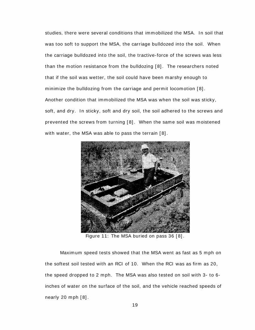
studies, there were several conditions that immobilized the MSA. In soil that
was too soft to support the MSA, the carriage bulldozed into the soil. When
the carriage bulldozed into the soil, the tractive-force of the screws was less
than the motion resistance from the bulldozing [8]. The researchers noted
that if the soil was wetter, the soil could have been marshy enough to
minimize the bulldozing from the carriage and permit locomotion [8].
Another condition that immobilized the MSA was when the soil was sticky,
soft, and dry. In sticky, soft and dry soil, the soil adhered to the screws and
prevented the screws from turning [8]. When the same soil was moistened
with water, the MSA was able to pass the terrain [8].
Figure 11: The MSA buried on pass 36 [8].
Maximum speed tests showed that the MSA went as fast as 5 mph on
the softest soil tested with an RCI of 10. When the RCI was as firm as 20,
the speed dropped to 2 mph. The MSA was also tested on soil with 3- to 6-
inches of water on the surface of the soil, and the vehicle reached speeds of
nearly 20 mph [8].

20
The overall performance of the MSA can be simplified to less friction is
better, and although soft soil is typically ideal it cannot be generalized as
being optimum. For example, soft soil can allow the vehicle to sink and
bulldoze. In addition, drawbar-pull tests showed maximum pull test values
at an RCI of 40, because the soil was firm enough to limit rutting but soft
enough to allow blade penetration [8]. A potential solution to the first issue
is to design a vehicle in which the screws provide sufficient flotation to keep
the hull out of the soil.
2.3.3 Snow. The MSA was also tested in deep snow. Based on the
results of the fine-grain soil testing, snow has ideal characteristics for
locomotion. The actual report concerning the snow tests could not be
obtained, but a paper summarizing the various MSA trafficability tests
mentions that the MSA reached speeds of 20 to 25 mph in deep snow [1]. In
comparison to the speeds of 2 to 5 mph in dry soil, it is evident that the MSA
performs well in snow. The MSA travelled at approximately 20 mph in mud
with a large layer of water, slightly slower than snow, further emphasizing
the importance of low friction on the performance of the MSA.
2.3.4 Water. Dr. Cole performed a variety of tests on screws in
water. He placed the screws in four different water depths to observe the
differences in torque and thrust. Specifically, he experimented with the
screw-axis 12-inches below the surface and 3-inches below the surface, the
blade-tip slightly breaking the surface, and with the screw-axis directly at the
surface [14]. When the depth of immersion was less, the torque and thrust
decreased [14]. Specifically, when the screw was exposed to air, the torque

21
and thrust significantly dropped [14]. Clearly, the torque and thrust reached
a maximum at the deep immersion condition. With the screw-axis
submerged 12-inches, the torque and thrust were nearly proportional to the
square of the rotational speed of the screw [14]. Dr. Cole ran the screws at
speeds of up to 2300 RPM with no cavitation [14].
Tests were also performed in water on the MSA. The primary
observations made from tests in water were that it was stable in water and
responded readily to steering [8]. In addition, the maximum speed the MSA
travelled at in water was 5 to 6 mph [8]. The speed the MSA travelled at in
water was similar to the soft, dry terrain but not as fast as the soft and wet
terrain.
Figure 12: The RUC performing a mine sweep test [2].
2.3.5 Trafficability Tests Summary. From the testing on the MSA,
it was concluded that its performance spectrum was the opposite of wheeled
and tracked vehicles. Specifically, the MSA performed better in wet and soft
soils of low friction in comparison to dry, firm, frictional soils [1]. They also
concluded that it was largely unaffected by vegetation, it worked well in

22
water and worked best in mud, excluding sticky mud, of low water content,
that is firm enough to walk on. Sticky, dry and firm mud had a tendency to
stick to the screws enough to seize them up [1]. Also, it was shown that the
screw vehicle should be heavy enough for blade penetration, but not so
heavy that the power required to rotate is too large.
The trafficability tests discussed provide a detailed account of a screw-
vehicle’s performance. However, all of the testing reviewed has been limited
to double-screw-vehicles. Furthermore, after Chrysler’s MSA testing, they
concluded that future tests were desirable for hard-ground maneuverability
and for improvements in sand [15].

23
CHAPTER 3: THE DOUBLE-SCREW
3.1 Capabilities
All of the studies discussed thus far were about vehicles with a single
pair of opposite-handed screws. In this thesis, the screw configuration just
described is called the double-screw, and applies to any vehicle or robot that
employs this mode of locomotion. As will be discussed, many more
configurations of screws can exist for a screw-vehicle, so the names must be
kept simple.
In this study, three basic motions are necessary for a screw-vehicle to
be considered omnidirectional.
• Longitudinal: Forward and backward locomotion.
• Lateral: Transverse locomotion similar to a crab’s locomotion.
• Rotational: Locomotion that is ideally about the vehicle’s center.
Figure 13 shows the forces imparted on left- and right-handed screws
by a compliant surface. Specifically, figure 13 shows what is termed
tractive- and rolling-force in this study. The tractive-force is along the
screw’s axis while the rolling-force is directed perpendicular to the screw’s
axis. Clearly, tractive- and rolling-forces depend on the direction of rotation
and the handedness of the screw’s blade.

24
A) B)
C) D) Figure 13: Rolling- and tractive-forces imparted on screws by a soft terrain. A) Right-hand, clockwise B) Left-hand, clockwise C) Right-hand, counter-
clockwise D) Left-hand, counter-clockwise
The tractive- and rolling-forces are what cause locomotion. Therefore,
the tractive-force pushes a screw longitudinally forward or backward.
Alternatively, the rolling-force produces lateral, left and right, locomotion.
Through different orientations of screws and different directions of screw
rotation, a variety of directions of net locomotion are possible.
In this study, all of the screws were assumed to rotate at the same
speed. Therefore, all tractive-forces were considered equal, and all rolling-
forces were considered equal. However, the tractive- and rolling-forces were
not necessarily the same. The tractive- and rolling-forces weren’t always
considered the same because the magnitude of each force would vary
depending on the helix-angle, the friction between the screw and terrain, the
25
depth of penetration of the screw’s blade, the cohesion of particles within the
terrain, and the terrain’s softness.
3.1.1 Counter-Rotating Screws. With the double-screw,
longitudinal locomotion is achieved in water and soft terrain by simply
counter-rotating the screws at the same speed. On rigid surfaces, excluding
ice, the screws cannot easily dig into the ground, and so the tractive-forces
that produce forward or backward locomotion are negligible. On the
contrary, friction and, as a result, rolling-forces are sufficient for locomotion
on pavement. Since rolling-forces are friction dependent, on low-friction
water the rolling-forces are negligible compared to the tractive-forces.
Figure 14 shows the forces imposed on a pair of screws and the resulting
locomotion. It should be noted that by reversing the directions of the
counter-rotating screws the system moves in the opposite direction.

26
A) B)
C) Figure 14: Screws counter-rotating on different surfaces.
A) Compliant surface B) Rigid surface (small force) C) Water
3.1.2 Co-Rotating Screws. On paved ground, if both screws are
rotated in the same direction and speed, a crab-like, lateral locomotion is
produced. In contrast to longitudinal locomotion, pure lateral locomotion is
only possible on paved or other rigid surfaces. The fact that a double-screw
cannot move longitudinally but can move laterally on pavement is similar to
why the opposite is true of a bicycle. When the wheels on a bicycle are
counter-rotated, no meaningful locomotion is produced. However, forward
and backward locomotion is viable when rotated in the same direction. In
both cases the vehicles cannot travel along the axis of rotation and
locomotion is only produced when the wheels are moved in the same
direction.

27
In soft ground, a double-screw vehicle with co-rotating screws will
travel in a curved path. The path is more curved in softer soil because the
blades interact with the soil more. Therefore, pure lateral locomotion does
not occur on soil for a double-screw. Similarly, lateral locomotion is not
possible on water with a double-screw. On water, the rolling-force of the
screw is negligible, and the screws produce a net rotational locomotion.
Figure 15 illustrates how a double-screw moves on different surfaces when
the screws are turned in the same direction. Again, reversing the direction of
the screws will move the double-screw in the opposite direction.
A) B)
C) Figure 15: Screws co-rotating in different terrains.
A) Compliant surface B) Rigid surface C) Water
3.1.3 Turning. The method and capability of turning depends on the
type of ground a double-screw is on. When aground, one method of turning
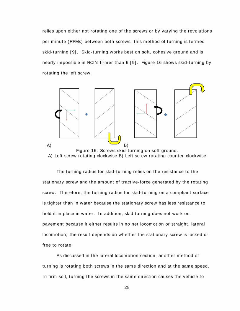
28
relies upon either not rotating one of the screws or by varying the revolutions
per minute (RPMs) between both screws; this method of turning is termed
skid-turning [9]. Skid-turning works best on soft, cohesive ground and is
nearly impossible in RCI’s firmer than 6 [9]. Figure 16 shows skid-turning by
rotating the left screw.
A) B) Figure 16: Screws skid-turning on soft ground.
A) Left screw rotating clockwise B) Left screw rotating counter-clockwise
The turning radius for skid-turning relies on the resistance to the
stationary screw and the amount of tractive-force generated by the rotating
screw. Therefore, the turning radius for skid-turning on a compliant surface
is tighter than in water because the stationary screw has less resistance to
hold it in place in water. In addition, skid turning does not work on
pavement because it either results in no net locomotion or straight, lateral
locomotion; the result depends on whether the stationary screw is locked or
free to rotate.
As discussed in the lateral locomotion section, another method of
turning is rotating both screws in the same direction and at the same speed.
In firm soil, turning the screws in the same direction causes the vehicle to

29
travel in a wide arc, and this turning is called arc-turning [9]. In soft
cohesive ground, such as marsh, turning the screws in the same direction
causes the vehicle to turn in a much tighter circle and is termed pivot-turning
[9]. During pivot-turning, the blades dominate the direction in which the
vehicle travels and produce a tight pivot [9]. Similarly, in water, any lateral
locomotion produced by the rotation of the drums is negligible and the effect
of the blade is dominant. Therefore, a double-screw will turn approximately
about its center on water when the screws are rotated in the same direction.
Figure 15 in the co-rotation section shows pivot-turning, arc-turning, and
turning in water.
Finally, on pavement, no combination of screw motions can allow a
double-screw to turn, except potentially on ice. There were no resources
describing turning capability on ice found. Nonetheless, an exception to the
lack of turning capability of a double-screw on rigid surfaces is the patented
Tyco® Terrain Twister, a plastic radio-controlled toy. The Terrain Twister
has the ability to hinge its screws several degrees about the vertical axis of
their center points. The turning radius of a hinging, double-screw on
pavement is given by formula 1 and is shown in figure 17.
r =c
2sin θ` a
fffffffffffffffffffffffff+ l2ffff (1)
Where:
r= Turning radius
c= Center-to-center of screws
θ= Hinge-angle
l= Drum-length

30
Figure 17: The turning radius of hinged-screws.
The turning radius is smallest when θ=90o, as shown in formula 2 and
figure 18.
Figure 18: The minimum turning radius for hinged-screws.
r =c2ffff+ l
2ffff (2)

31
3.2 Limitations
The double-screw is capable of moving in many directions and over a
wide range of terrains. However, they are not fully omnidirectional and their
locomotion capabilities vary depending on the terrain. This section
discusses, in detail, the limitations of the double-screw from the perspective
of omnidirectional locomotion. A discussion for each limitation is given
regarding if it can be remedied with a different configuration of screws.
The first limitation of a double-screw to consider is its inability to move
longitudinally on a rigid surface. Unfortunately, due to the nature of screw
locomotion, there may be little that can be done to improve longitudinal
locomotion on pavement. As will be discussed, a solution is to employ a
combination of lateral locomotion and rotation to overcome rigid obstacles
such as pavement.
Another limitation of the double-screw is the impure lateral movement
on all but the most rigid surfaces. Clearly, controlling a vehicle can be
cumbersome if it tends to follow an arced path. Furthermore, control issues
are exacerbated by the variable nature of the arc. Specifically, a double-
screw makes a wide arc on firmer ground but nearly turns about its center on
soft soil. As will be discussed, this issue can also be overcome with another
configuration of screws.
The final limitation of the double-screw is rotation. Although turning is
possible on all surfaces, the efficacy and method of turning is not consistent
for each surface. An ideal system would employ the same method of turning
on any surface and always be capable of turning about its center.

32
One of the turning methods discussed was skid-turning. Skid-turning
is incapable of turning the vehicle directly about its center point. As a result,
skid-turning requires more space for maneuvering than an ideal turning
method. Furthermore, the stationary screw is forced to skid or plow across
the surface of the ground, thereby reducing turning time and possibly
damaging the screw thread. Tests performed on the RUC show that pivot-
turning is quicker than skid-turning on soils in which both are possible [9].
Turning is possible on hard surfaces by utilizing hinged-screws. In the
case of the Terrain Twister, its unique hinged-screws allow for steering on
hard surfaces, but since the screws do not hinge 90o, the turning radius is
not about its center. Furthermore, the action of hinging the screws takes
time and may damage the screws or pavement by scraping the blades along
the surface. In all, the benefit of hinged-screws may be further reduced due
to complicated design. In particular, hinged-screws require more joints than
a non-hinging double-screw and require a mechanism, such as an actuator,
to perform the hinging motion.

33
Figure 19: An example of hinged-screws.
Finally, when rotating the screws in the same direction on increasingly
soft soils, arc- and pivot-turning is possible. The degree of arc in the path
depends on the helix-angle, the weight of the vehicle and the softness of the
soil. The issue of firm soil, in which the blades cannot fully dig into the soil,
is clear because the turning radius is wide. However, even when the double-
screw is pivot-turning on very soft soil, it does not turn about its center.

34
CHAPTER 4: ALTERNATIVE SCREW CONFIGURATIONS
4.1 Overview
Chapters 2 and 3 discussed the issues that the double-screw has
regarding locomotion on different terrains. Nonetheless, a screw-vehicle, in
general, likely has the potential to overcome many of the limitations of a
double-screw. Several new screw configurations have been considered prior
to building a test-bed. This chapter outlines the assumptions and analysis
made about each configuration of screws considered.
This chapter includes vector analysis for screw configurations of
interest. Additional vector analyses are provided in appendices A through C.
In vector analyses in this chapter and appendices A through C, tractive-
forces are red arrows, as are the moments resulting from those tractive-
forces; while the rolling-forces are green arrows, as are the moments
resulting from the rolling-forces. Lastly, yellow arrows indicate the net
direction of locomotion.
4.2 Bendable-Screw
Among the first solutions considered to resolve the limitations of the
double-screw was the adoption of a bendable-screw. The concept of the
bendable-screw was that it could be bent to steer the vehicle. By bending

35
the ends of the screws toward the vehicle’s hull, rotation about the center of
the vehicle may be possible. Furthermore, by bending the front of both
screws either left or right, the vehicle may be able to travel in the direction
the screws point to.
In theory, bendable-screws may be promising from the perspective of
turning. However, two bendable-screws alone would not resolve the issue of
arced locomotion. Furthermore, there were many complications that could
have arisen when developing a bendable-screw.
A known issue was that bending a screw places tension on one side of
the screw and compression on the other side. When the screw begins
rotating, the tension and compression alternates, resulting in cyclical stress.
The cyclical tension- and compression-stresses imposed on the blades could
have resulted in failure.
Figure 20: Red and blue halves experiencing alternating tension.
If a material was used that could withstand the alternating stresses
imposed by bending a rotating screw, another complication would have still
existed. In order for a bendable-screw to work, it was important that the

36
screw remain flat on the ground while it rotated about its center axis. A
likely problem was that the screw may rotate about the axis projected
through its two endpoints. The result would have been a screw that rotates
similar to a jump-rope and with no effect from the blades. In summary,
since the best design is the simplest design, the bendable-screw was not
pursued.
Figure 21: Modes of rotation for a bendable-screw.
4.3 Split-Screw
Another configuration considered for a screw-vehicle was one with four
screws. Specifically, the screws would be oriented in a box formation in
which the front- and rear-screws would be axially aligned and the screws on
the left and right side would be fixed parallel to each other. The parallel
screws would have opposite blade handedness, similar to the double-screw,
while the screws directly behind the front-screws would have the same blade
handedness as those directly in front of them. The configuration described is
essentially the same as the double-screw with the freedom to rotate the

37
front- and rear-screws independently. Therefore, the screw configuration
described is called the “split-screw” throughout this thesis.
Figure 22: Top view of the split-screw layout.
From the perspective of skid-turning, moving forward, backward, and
laterally, the split-screw was presumed to act the same as a vehicle with two
screws. In order to behave exactly like a double-screw, the screws in the
rear must turn in the same direction and speed as the screws directly in
front. As shown in figure 23-B, straight lateral locomotion was not
considered possible in soft soils.
The assumed advantage of the split-screw over the double-screw was
turning could become possible on solid surfaces and improve on soft
surfaces. Turning was thought to be similar to a tank. When the screws in
the front are rotating in the same direction and the screws in the rear are
rotating in the other direction, the vehicle could possibly turn about its center
on hard and soft surfaces. Figure 23-C shows a vector analysis of a rotating
split-screw. Clearly, the tractive- and rolling-forces cancel and the moment
due to tractive-forces cancel, leaving the moment due to rolling-forces to
generate clockwise rotation.

38
In summary, full experimental testing was not carried out on the split-
screw because it showed minimal improvement over the double-screw,
except that it could rotate about its center. Since it was critical that a screw-
configuration be developed that could move in a straight, lateral direction on
any surface, more configurations were investigated.
A) B)
C) D) Figure 23: Four symmetric screw rotations for the split-screw.
A) No locomotion B) Lateral (impure skew motion) C) Rotational D) Longitudinal

39
4.4 Inline-Screw
Another configuration utilizing four screws which was considered was
one in which the screws are similar to the split-screw. However, each
screw’s handedness alternates. As a result, the described screw
configuration is unique to the double-screw. Therefore, the screw
configuration described is termed “inline-quad-screw”, or simply inline-screw,
in this thesis.
Figure 24: A top view of the inline-screw.
Figure 24 illustrates the inline-screw configuration specifically used for
the test-bed. An alternative inline-screw configuration has each left- and
right-handed screw switched; this screw-pattern is termed the mirrored-
inline-screw in this study. Appendix C shows the vector analyses for the
mirrored-inline-screw.
For the inline-screw, longitudinal locomotion is not achieved in the
same manner as the double-screw or the split-screw. Instead, in order to go
forward and backward, the front must be counter-rotated and the back must
be counter-rotated in the opposite direction of the front. To get rotation

40
about the vehicle’s center, the front-screws are rotated in one direction while
the rear-screws are rotated in the opposite direction.
Similar to the split-screw, the inline-screw can rotate about its center.
Furthermore, its turning radius is dictated by the size of the vehicle. The
turning radius of the inline-screw is given by formula 3 and is shown in figure
25.
Figure 25: The turning radius of an inline-screw.
r =Track
2ffffffffffffffffffff
hj
ik
2
+Wheelbase
2fffffffffffffffffffffffffffffffffffffff
hj
ik
2vuuuut
wwwwwwwwwwwwwwwwwwwwwwwwwwwwwwwwwwwwwwwwwwwwwwwwwwwwwwwwwwwwwwwwwwwwwwwwwwwwwwwwwwwwwwwwwwwwwwwwwwwwwwwwwwwwwwwwwwwwwwwwwwwwwwwwwwwwwwwwwwwwwwwwwwwwwwwwwwwwwwwwwwwwwwwwwwwwwwwwwwwwwwwwwwwwwwwwwwwwwwwwwwwwwwwwwwwwwwwwwwwwwwwwwwwwwwwwwwwwwwwwwwwwwwwwwwwwwwwwwwwwwwwwwwwwwwwwwwwwwwwwwwwwwwwwwwwwwwwwwwwwwwwwwwwwwwwwwwwwwwwwwwwwwwwwwwwwwwwwwwwwwwwwwwwwwwwwwwwwww
(3)

41
Figure 26: The turning radius of an inline-screw superimposed on a hinged
screw’s turning radius.
A major advantage of the inline-screw over the split-screw was
determined to be when attempting lateral locomotion in soft, wet terrain.
Since the screws are of opposite direction on the inline-screw, the front- and
rear-screws were presumed to attempt to travel in opposing arced paths.
The result would be cancelation of both arced paths and the creation of a
straight, lateral path. More specifically, all of the moments created by the
tractive-forces cancel out during lateral motion. Since the inline-screw shows
promising directions of locomotion, it was chosen to undergo all of the tests
in this study.

42
A) B)
C) D) Figure 27: Four symmetric screw rotations for the inline-screw.
A) Longitudinal B) Lateral C) Rotational D) No locomotion
Comparing figure 27 to figure 28 shows that reversing the direction of
each screw’s rotation, for each symmetric switch pattern, results in the
inline-screw moving in the opposite direction. This is true for all double- and
quad-screw-configurations.

43
A) B)
C) D) Figure 28: Reversing the direction of rotation for each symmetric switch
pattern results in the opposite direction of locomotion. A) Backward B) Left C) Counter-clockwise D) No locomotion
44
Figure 29: Model of the inline-screw.
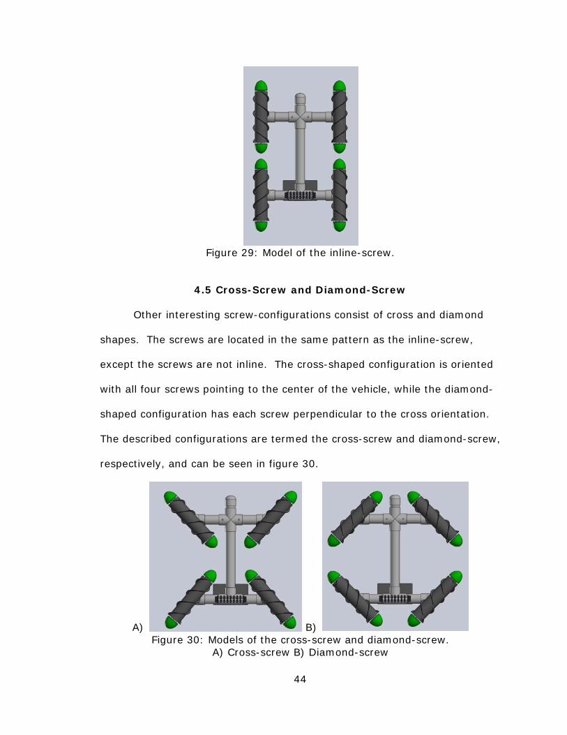
4.5 Cross-Screw and Diamond-Screw
Other interesting screw-configurations consist of cross and diamond
shapes. The screws are located in the same pattern as the inline-screw,
except the screws are not inline. The cross-shaped configuration is oriented
with all four screws pointing to the center of the vehicle, while the diamond-
shaped configuration has each screw perpendicular to the cross orientation.
The described configurations are termed the cross-screw and diamond-screw,
respectively, and can be seen in figure 30.
A) B) Figure 30: Models of the cross-screw and diamond-screw.
A) Cross-screw B) Diamond-screw

45
Clearly, the diamond-screw and cross-screw can also exist for the
split-screw configuration. Figures 32 and 33 show the vector analyses of the
cross-screw and diamond-screw, while appendices A and B show the split-
screw’s cross- and diamond-shaped vector analysis. A review of each vector
analysis reveals that the cross-screw and diamond-screw are superior to
their split-screw counterparts. Therefore, the split-screw’s cross- and
diamond-shaped configurations are not tested in this study. Furthermore, for
simplicity, the split-screw’s cross- and diamond-shaped configurations are
called the S-cross-screw and S-diamond-screw. Finally, just as there is a
mirrored version of the inline-screw, there are mirrored versions of the
diamond-screw and cross-screw. Only one version of the diamond-screw and
cross-screw were tested. The diamond-screw and cross-screw had their
screws in the same order as the inline-screw that was tested.
Unlike the inline-screw proposed here, the cross-screw and diamond-
screw are not new, but were discovered during a patent search of screw-
vehicles. The order of screws for the diamond-screw and cross-screw in the
patent matched the order tested in this study. Since the diamond-screw and
cross-screw were patented concepts with no evidence of a scientific study,
they were tested in all of the same conditions as the inline-screw.
Furthermore, by testing the cross-screw and diamond-screw, the roles of the
tractive- and rolling-forces were better understood.

46
Figure 31: The patented cross-screw and diamond-screw configurations [16].
A) B)
C) D) Figure 32: Four symmetric screw rotations for the diamond-screw.
A) Longitudinal (forward or reverse is indeterminate) B) Lateral C) Rotational D) No locomotion

47
A) B)
C) D) Figure 33: Four symmetric screw rotations for the cross-screw.
A) Longitudinal B) Lateral (left or right is indeterminate) C) Rotational D) No locomotion

48
CHAPTER 5: THE TERRAIN TWISTER
5.1 Description
The Tyco® Terrain Twister is a remote controlled toy that uses two
screws to drive. It uses two DC motors to individually power the screws.
These motors are housed in a watertight plastic shell and are located inside
the screws. The motors turn a plastic tab, clipped to the inside of the screw,
to turn the screw.
Each of the Terrain Twister’s screws is made of two hollow plastic
shells that fit around a rod, motor, and Styrofoam. The rods are used to hold
the screws and motors in position and they are held in place by forks that
attach to both ends of the rods. The forks both mount to the body of the toy
which contains all of the electrical and radio signal components. The toy also
has gears that rotate the forks so the screws can hinge inward and outward
allowing for turning on hard surfaces.

49
Figure 34: The Terrain Twister screw-assembly.
5.2 Test-Bed Construction
The Tyco® Terrain Twister was useful for the quad-screw test-bed
because it already consisted of screws that work effectively on water, dirt,
snow, sand, and to a limited extent, hard surfaces. From the studies
reviewed in chapter 2, the screws that came with the Terrain Twister had a
geometry that closely matched an ideal screw for most terrains. Table 1
compares the geometry of the Terrain Twister screws to an ideal geometry.
The only parameter that did not closely match the ideal screw geometry was
the length-to-drum-diameter ratio. Nonetheless, the geometry was
acceptable. All of the geometric values for the Terrain Twister’s screws are
provided in appendix D with calculations for the values in Table 1.

50
Table 1: Terrain Twister screw geometry Parameter Terrain Twister Ideal Comments
Helix angle (o)31.03 30 or slightly larger [3,14]
Blade height to diameter ratio
0.125 0.125 center diameter measurement [3]
Number of helix blade starts
2 2 [3,14]
Length to diameter ratio
3.65 6 center diameter measurement [3]
Blade thickness (inches)
0.0625 -no information on
performance impact
The Terrain Twister screw was also convenient. The screw already had
a motor housed inside it, allowing any combination of screw rotations to be
performed. Specifically, the individual motors eliminated the need for
complicated gearing, belts, or any other transmission system. Also, the
screws were lightweight enough to easily float in water with additional
buoyancy. Although the Terrain Twister was convenient, it was no longer
marketed at the time of this study. Therefore, Terrain Twisters were
purchased through Ebay, an online auctioning service.
The two fork-and-screw-assemblies were permanently removed from
the body of the Terrain Twister to mount to the frame of the test-bed. Since
the test-bed used four screws, two Terrain Twisters were utilized. The
Terrain Twister was disassembled so that the forks and screws remained
intact. The wires leading from the motors were also kept intact so that they
could be used in the wiring of the test-bed.
51
5.3 Test Comparison
The testing which will be discussed in chapter 7 sought to understand
the advantages and limitations of each quad-screw configuration by
observing behavior on different terrains. However, in order to make sense of
the observations, comparisons were made using a double-screw and the
quad-screw configurations with identical screws. By testing the double-screw
in each terrain, it was possible to note if the vehicle behaved in the manners
described in previous research. When the double-screw operated as
discussed in other papers, it demonstrated that the screw’s geometry and
scale were appropriate for testing the quad-screw configurations.

52
CHAPTER 6: QUAD-SCREW TEST-BED CONSTRUCTION
6.1 Test-Bed Frame
The frame of the test-bed served as a compartment for batteries and a
mounting surface for the screw-assemblies, the switchbox and other
electrical components. Therefore, the material selected for the frame was
important. The entire frame of the test-bed was made of schedule 40 PVC
because it was lightweight, sturdy, hollow, easy to assemble, and readily
available.
A single piece of 1.25-inch diameter PVC was used for the body to
house D-cell batteries, used to power the test-bed, and provide appropriate
spacing between the screws. The total length of the body piece provided a
1-inch gap between the ends of each screw. The 1-inch gap existed between
the front- and rear-screws when in the inline-screw configuration.
53
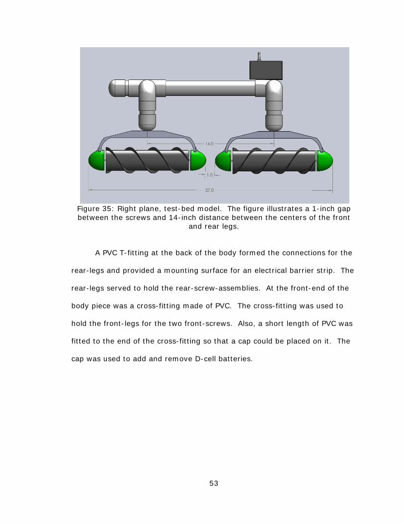
Figure 35: Right plane, test-bed model. The figure illustrates a 1-inch gap between the screws and 14-inch distance between the centers of the front
and rear legs.
A PVC T-fitting at the back of the body formed the connections for the
rear-legs and provided a mounting surface for an electrical barrier strip. The
rear-legs served to hold the rear-screw-assemblies. At the front-end of the
body piece was a cross-fitting made of PVC. The cross-fitting was used to
hold the front-legs for the two front-screws. Also, a short length of PVC was
fitted to the end of the cross-fitting so that a cap could be placed on it. The
cap was used to add and remove D-cell batteries.
54
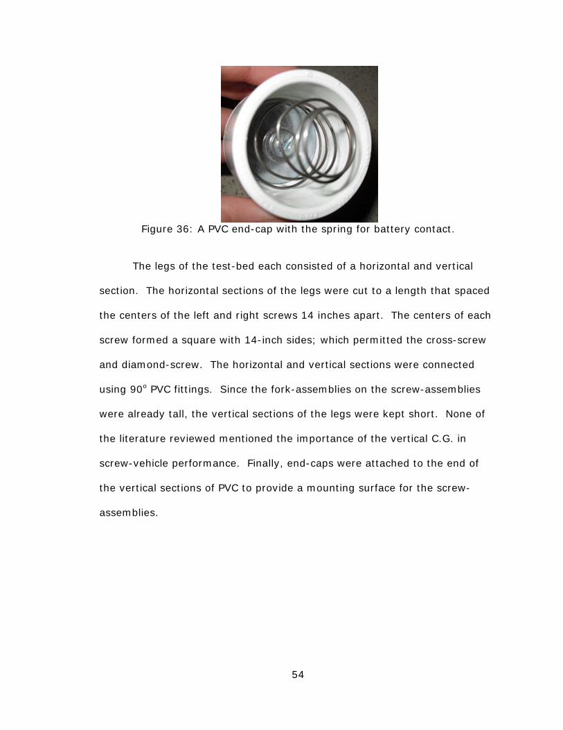
Figure 36: A PVC end-cap with the spring for battery contact.
The legs of the test-bed each consisted of a horizontal and vertical
section. The horizontal sections of the legs were cut to a length that spaced
the centers of the left and right screws 14 inches apart. The centers of each
screw formed a square with 14-inch sides; which permitted the cross-screw
and diamond-screw. The horizontal and vertical sections were connected
using 90o PVC fittings. Since the fork-assemblies on the screw-assemblies
were already tall, the vertical sections of the legs were kept short. None of
the literature reviewed mentioned the importance of the vertical C.G. in
screw-vehicle performance. Finally, end-caps were attached to the end of
the vertical sections of PVC to provide a mounting surface for the screw-
assemblies.

55
Figure 37: Front plane, test-bed model. This figure illustrates the 14-inch
distance between the centers of the left and right legs.
Figure 38: Trimetric, test-bed model.

56
Figure 39: A photograph of the test-bed.
6.2 Screw-Assemblies
The screw-assemblies consisted of a fork-assembly, a motor and the
screw. More detail is provided, regarding the components of the screw-
assemblies, in section 5.1. The two screw-assemblies were permanently
removed from the body of the Tyco® Terrain Twister to mount to the frame
of the test-bed. Since the test-bed used four screws, two Terrain Twisters
were utilized. Bolts were fed through the center of the forks to attach to the
PVC end-caps. The end-cap was able to twist about the PVC legs to allow the
screws to be positioned for the inline-screw, cross-screw, or diamond-screw
configurations.

57
6.3 Wiring and Controls
Several considerations had to be made concerning the wiring in order
to build a successful test-bed. The wiring of the test-bed had to be able to
withstand frequent transportation, rough off-road terrain and watery
conditions. Furthermore, it had to be easy to access the wires to make
modifications or repairs. Finally, the wiring had to result in logical controls
that would be easy to remember.
The wires within the Terrain Twister motors were utilized in the test-
bed circuitry. The motor wires were soldered to longer wires and insulated
with shrink-tubing. With four motors containing two wires per motor, a total
of eight wires were connected to an electrical barrier strip. The barrier strip,
located on the underside of the T-fitting, consisted of eight pairs of terminals
and two holes for mounting it. Each wire that led from the motor to the
barrier strip had a corresponding 6-foot wire that led from the barrier strip to
the switch box. Sections of shrink tubing were placed around all of the 6-
foot wires to neatly hold them together like a cable tether.
The wires leading to the barrier strip were all color coded to prevent
confusion. Specifically, the right-handed screws had purple and blue wires
while the left-handed screws had orange and white wires. The purple wires
were the same polarity as the orange wires, while the blue and white wires
shared the same polarity as well. Wires from the front-screws led to the
outer barrier strip terminals and wires from the rear-screws led to the inner
barrier strip terminals. Furthermore, the screws on the left side of the
vehicle led to the left terminals on the barrier strip and vice versa.

58
Figure 40: The barrier strip wiring.
To supply power to the circuit, a brown wire was attached to the bolt
at the end-cap and a gray wire was attached to the bolt at the rear T-fitting.
The bolts that the brown and gray wires were connected to were used to hold
springs that contacted the D-cell batteries. The brown and gray wires were
connected to the barrier strip with a ring terminal secured to the bolts that
mounted the barrier strip to the frame. In total, there were ten wires leading
into the barrier strip.
Each wire leading to the barrier strip consisted of a corresponding wire
that was soldered to a switchbox. The switchbox contained four 3-position
switches. On each switch, the center position did not supply power and the
forward- and backward-positions did. The switches were positioned in the
same order as the barrier strip. In other words, the outside switches were
for the front-screws and the left switches were for the left-screws.

59
The individual switches consisted of six terminals; two in the front, two
in the middle and two in the back. For a given motor, a wire of one polarity
was soldered to the back-left-terminal and the wire of opposite polarity was
soldered to the back-right-terminal. A wire from each terminal was directed
to the terminal diagonal from it to reverse the polarity when the switch was
flipped to the front. The wires that provided the power were soldered to the
middle terminals such that one polarity was soldered to the middle-left
terminal and the opposite polarity was soldered to the middle-right terminal.
The first switch, for the front-left-screw, was directly connected to the power.
The remaining switches were provided power by wiring them in parallel with
the first switch. The described wiring was done by chaining the middle
terminals to the middle terminals of the adjacent switch until all were
electrically in contact.
Figure 41: The switchbox wiring.
In order to have the correct amount of batteries, a spacer assembly
was built. The spacer assembly consisted of a 0.75-inch diameter PVC pipe
with two caps placed on either end. The overall length of the spacer was 3-
inches. Each cap had a hole drilled in the center so a screw could pass
60
through them. The spacer was then bolted to the inside of the T-fitting so
one end was firmly in contact with the inside surface of the T-fitting. Finally,
a spring and washer were secured to the opposite end of the spacer. The
purpose of the spring and washer was to provide an electrical connection
between the batteries.
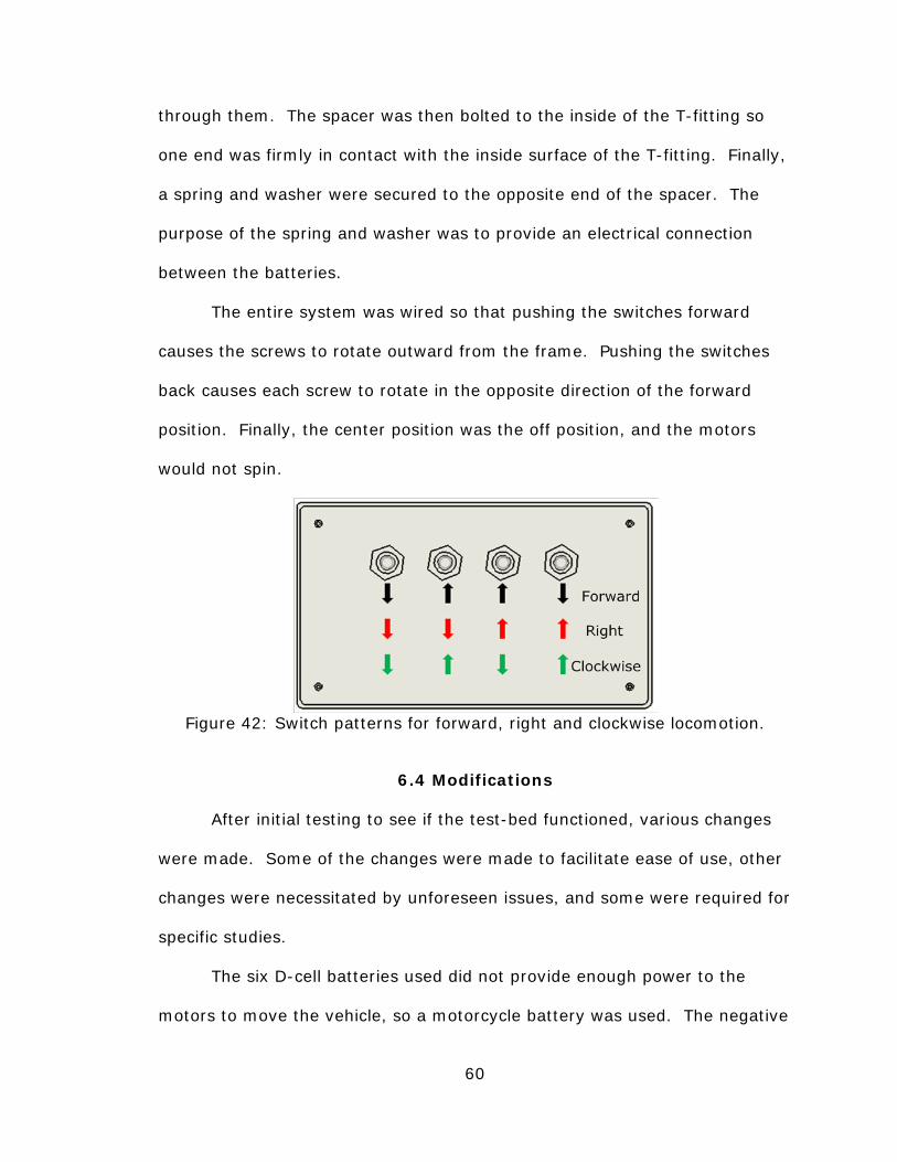
The entire system was wired so that pushing the switches forward
causes the screws to rotate outward from the frame. Pushing the switches
back causes each screw to rotate in the opposite direction of the forward
position. Finally, the center position was the off position, and the motors
would not spin.
Figure 42: Switch patterns for forward, right and clockwise locomotion.
6.4 Modifications
After initial testing to see if the test-bed functioned, various changes
were made. Some of the changes were made to facilitate ease of use, other
changes were necessitated by unforeseen issues, and some were required for
specific studies.
The six D-cell batteries used did not provide enough power to the
motors to move the vehicle, so a motorcycle battery was used. The negative

61
battery terminal was wired directly to one of the barrier strip mounting bolts.
The positive terminal was wired to a kill-switch that was wired to the other
barrier strip mounting bolt. Since the battery was bulky, it was kept in a
backpack and worn on the tester while the vehicle was driven. Likewise,
since the long cable used for the switchbox was clumsy and all of the testing
occurred with one locomotion at a time, the switchbox tether was removed
and the switchbox was mounted to the rear of the test-bed with Velcro.
Figure 43: The author shown alongside the test-bed. A motorcycle battery in
a backpack is utilized to power the test-bed.
Over time, PVC began to expand at the joints. Initially, the joints were
held together with tight press-fits. However, the expansion of the PVC
caused each joint to become loose, and the vehicle flexed during testing. In
order to remedy the situation, PVC cement was used for permanent joints.
Since the screws had to be able to hinge for the cross-screw and diamond-
screw, the end-caps that the screw-assembly mounted to were not glued.

62
Instead, masking tape was used to allow easy adjustment of the screw’s
hinge-angle.
Though an advantage of a screw-vehicle is the potential for floating
screws, the test-bed did not have adequate screw buoyancy to keep it afloat.
Instead, the Terrain Twister utilized a plastic hull, filled with Styrofoam, to
maintain buoyancy. Therefore, in order to investigate various quad-screw
configurations in water, a floating hull was constructed. Hollow cylindrical
foam was used to provide buoyancy on water for the test-bed vehicle.
Twelve-gauge wire provided a sturdy framework to hold the foam in position
when the vehicle was in water. Finally, to provide stability, small sections of
foam were placed between the front- and rear-screws. When the vehicle was
in the cross-screw or diamond-screw configuration, the screws held the long
foam cylinder in the center so that the additional small sections of foam were
not needed.
Figure 44: The floating test-bed setup.
63
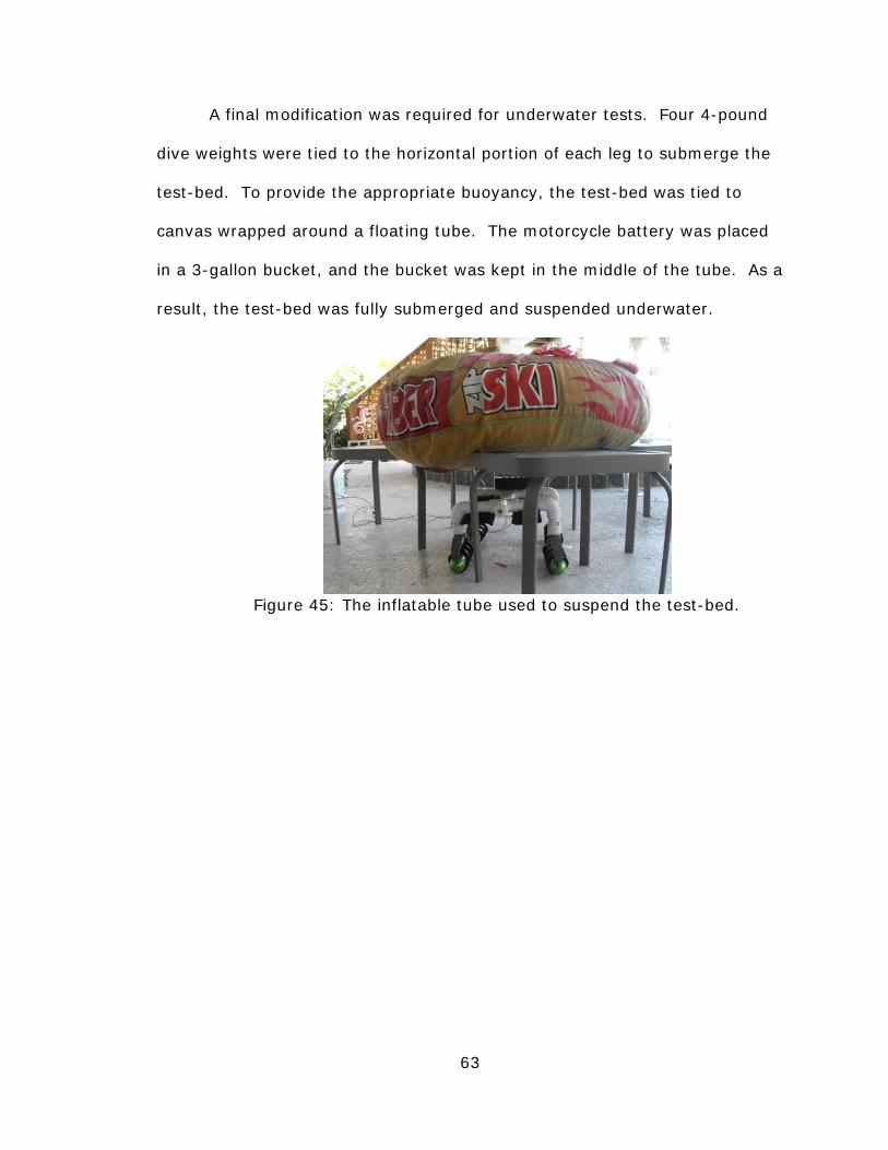
A final modification was required for underwater tests. Four 4-pound
dive weights were tied to the horizontal portion of each leg to submerge the
test-bed. To provide the appropriate buoyancy, the test-bed was tied to
canvas wrapped around a floating tube. The motorcycle battery was placed
in a 3-gallon bucket, and the bucket was kept in the middle of the tube. As a
result, the test-bed was fully submerged and suspended underwater.
Figure 45: The inflatable tube used to suspend the test-bed.

64
CHAPTER 7: EXPERIMENTS
7.1 Experimental Goals
The goal of the experiments herein was to provide insight into the
locomotion of the inline-screw, cross-screw and diamond-screw in different
terrains when attempting longitudinal, lateral and rotational locomotion.
Initial tests were performed to observe the direction of locomotion for each
configuration on each terrain. Further tests were performed to determine the
maximum velocity of each configuration on each terrain.
In the literature reviewed, drawbar-pull capacity and power and torque
requirements were of interest for designing a full-scale tank. However, in
this study, power and torque requirements and drawbar-pull capacity were
not a concern. Again, the primary goal of this study was to investigate
alternatives to the double-screw to find the best configuration from the
standpoint of omnidirectional locomotion. Therefore, vector analyses,
observations on vehicle trafficability and calculations of maximum velocity
were adequate to determine which configuration had the best omnidirectional
capability.
As discussed in chapter 2, the double-screw was thoroughly
researched on a wide gamut of terrains. Therefore, since the behavior of a
double-screw was already known, it was also tested for the purpose of
65
comparison. In particular, the Terrain Twister was used for the double-screw
tests.
From the previous research available, screw-vehicle performance due
to screw design parameters and screw-to-terrain interaction was given.
Therefore, further testing on screw design optimization was unnecessary for
the research in this thesis. In addition, as discussed in chapter 5, the screws
utilized by the Terrain Twister and the test-bed closely matched the screw
geometry of an all-terrain vehicle. Therefore, testing could be performed on
nearly any surface.
The force-vector analyses in chapters 3 and 4 and compiled in
appendices A through C provided a model for predicting the direction of
locomotion for each configuration. Since no benefit was predicted from the
split-screw, the S-cross-screw, or the S-diamond-screw over their
counterparts, the inline-screw, cross-screw and diamond-screw, minimal
testing was performed on them. Nonetheless, testing was performed on the
split-screw in grass, pavement and water to validate the force-vector
diagrams used.
7.2 Methodology
7.2.1 Test Locations. Specific test locations were selected to test
omnidirectional locomotion on a variety of terrains. The locations were
chosen such that each terrain consisted of a single medium over a large,
level surface. Each terrain was located as follows:
66
• Grass: Since grass was easy to find, several locations were
used. The requirements were that the ground was level with
minimal bumps and the grass was maintained at a height of 1-
to 2-inches.
• Dirt: A large area of loose dirt was found in Palm Harbor, FL. A
large section of flattened dirt was utilized for testing.
• Marsh: A marshy surface was exposed during low tides in the
Gulf of Mexico in the Palm Harbor, FL area. The marshy surface
was flat and consisted of seaweed vegetation on top of a
mixture of water-saturated dirt and sand.
• Sand: Dry sand was located in a volleyball court at the USF
Riverfront Park in Tampa, FL. The sand was raked to provide a
smooth testing surface.
• Clay: Dry clay was located at a baseball field at the USF
Riverfront Park in Tampa, FL. The clay was characterized by a
thin layer of loose clay particles at the surface and hard,
compact clay underneath.
• Pavement: The pool deck around the swimming pool used for
water testing was utilized for tests concerning pavement.
• Gravel: A gravel parking lot near a boat launch in Palm Harbor,
FL provided the gravel testing surface. The size of the gravel
averaged approximately 1-inch in diameter.
• Water: A swimming pool 30 feet long, 12.5 feet wide, and 4 to 8
feet deep was used for testing on the surface and underwater.

67
• Snow: The Tampa Bay Skating Academy in Oldsmar, FL
provided snow for testing. A large deposit of snow was provided
from the skating-rink’s ice resurfacing vehicle. The powdery
snow was leveled and spread using a rake to provide a large,
flat testing surface.
7.2.2 Testing Directions. Several directions of locomotion were
tested on each test site. The directions tested varied between the double-
screw and quad-screw configurations, because the double-screw could not
perform the same combinations of screw rotations. The directions tested in
each terrain were as follows:
• Double-screw: Longitudinal locomotion, lateral locomotion, skid-
turning
• Quad-screw configurations: Longitudinal locomotion, lateral
locomotion, rotational locomotion
In this thesis, lateral locomotion for the double-screw included straight
lateral movement, arc-turning and pivot-turning. While arc- and pivot-
turning were expected from the double-screw, only straight lateral
locomotion was acceptable for the quad-screw configurations.
Another distinction between the double- and quad-screw
configurations was they each rotated in a different manner. The quad-screw
configurations could rotate the front- and rear-sets of screws in the opposite
direction to rotate, so they had specific tests for rotational locomotion. Since
the double-screw could not rotate in the same manner as the quad-screw,
the effectiveness of skid-turning was observed for the double-screw instead.

68
7.2.3 Test Setup. At each test location, two pairs of cones were set
up. The first pair of cones marked the starting line and the second pair of
cones marked the finish line. Measuring tape was used to maintain 10 feet
between the inside of each pair of cones. The 10-foot course was used to
observe the behavior of the quad-screw configurations during longitudinal
locomotion on each terrain. As will be discussed, the diamond-screw was an
exception due to the limited capability of its longitudinal locomotion. The
cones were not used for the double-screw because it was not being
compared for speed or slip tests.
Figure 46: An example of the test setup.
For the inline-screw, the slip percentage was desired to be known to
understand its efficiency. In order to calculate the slip percentage, the
number of screw revolutions and the distance the vehicle moved in a given
time had to be known. White tape was placed on the screws of the test-bed
to count the number of revolutions, while the time it took to cross 10 feet
provided the speed. Since the screws moved at relatively high speeds,

69
Virtual Dub video editing software was used to observe the video frame-by-
frame to count the number of times the white tape showed up. Since the
screws were measured to rotate no faster than 550 RPMs, the camera
method was adequately accurate since it had 900 frames per minute.
Finally, the time to cover 10 feet was determined by the time elapsed on the
video when the back of the vehicle crossed the inside of the start and finish
cones.
All tests were recorded with a digital camera so that a video library
could be compiled. The library was useful for discussing the behavior of each
configuration, troubleshooting issues that occurred in the field, determining
the velocity of the quad-screw, and finding the RPMs of the screws.
7.3 Test Observations
7.3.1 Grass. On grass, longitudinal and lateral locomotion showed no
issues for the double-screw. Skid-turning was generally effective, but
occasionally the rotating screw would lose traction with the ground and no
movement would occur. In cases where skid-turning failed, the double-screw
was not immobilized because it could immediately move longitudinally.
Lateral locomotion for the double-screw resulted in arc-turning.
The inline-screw worked well on grassy surfaces. When it was set to
move longitudinally, it moved in a straight line with no issues. When it was
set to rotate, it rotated in a tight circle about its center-point. Finally, when
it was set for lateral locomotion, it moved in a straight lateral direction as

70
anticipated by the force-vector diagrams. In summary, no issues or
surprises arose for the inline-screw in grass.
Figure 47: Test setup for grass terrain.
The cross-screw was able to move longitudinally with no issues on
grass. Furthermore, it rotated much faster than the other configurations,
because the rolling-forces on each screw directly contributed to the rotation.
Unfortunately, the cross-screw did not move in a predictable manner for
lateral tests. When set to move right, based on the switch combination to
move the inline-screw right, it attempted to move right but it quickly and
frequently altered its path. Also, in some cases it did not go anywhere when
set for lateral motion. Clearly, since the rolling-forces attempted to pull the
cross-screw to the right while the tractive-forces tried to pull it to the left,
the system was unstable.
Unlike the cross-screw, the diamond-screw moved laterally in the set
direction with no issues. However, it did not rotate as fast as the inline-
screw or cross-screw. The diamond-screw relied only on tractive-forces for
turning. Finally, the diamond-screw did not successfully move longitudinally.
Similar to the cross-screw when attempting lateral locomotion, the diamond-

71
screw, when set to move longitudinally, encountered opposing tractive- and
rolling-forces. In the diamond-screw tests, it stayed in place while the
screws rotated.
7.3.2 Dirt. Most of the observations made from testing in grass
applied to the testing in dirt. Nonetheless, each configuration performed
slightly different in dirt compared to grass.
In dirt, the double-screw was able to move longitudinally, but it did
not perform as well as it did in grass. When it encountered inconsistencies in
the dirt, such as small hills or loose patches of dirt, it would slightly alter its
path or become immobilized; immobilization was infrequent. Lateral
locomotion rarely resulted in immobilization, but the double-screw followed a
wide arc. In addition, when attempting to skid-turn, the double-screw often
became immobilized. In nearly all cases of immobilization, it could be
extricated by lateral or longitudinal locomotion.
The inline-screw behaved similar to the double-screw during
longitudinal locomotion because it sometimes altered its path or became
immobilized when it encountered terrain inconsistencies. During lateral and
rotational locomotion, no issues were observed. Similarly, the cross-screw
performed as it did in grass, except it also did not perform as well
longitudinally. There were no cases of the cross-screw becoming
immobilized.

72
Figure 48: Tracks from the inline-screw deviating in dirt.
Regarding lateral motion, the diamond-screw behaved as expected by
moving in the proper direction and path with some path deviation due to
terrain inconsistency. However, when set to move longitudinally, the
diamond-screw behaved much different than in grass. Rather than going
nowhere, when set to move forward it attempted to go in reverse and quickly
buried itself or deviated its path erratically. In the case of the diamond-
screw on dirt, the reverse rolling-forces had slightly overcome the forward
tractive-forces. Finally, when attempting rotation, the diamond-screw could
make no more than two rotations before becoming immobilized. Since the
screws rotated at a fast speed, the diamond-screw may have kicked up the
dirt and buried itself when attempting to rotate. It is possible that slowing
the RPMs of the screws may resolve the issue of the diamond-screw burying
itself during rotation.

73
7.3.3 Marsh. The marshy terrain provided interesting information for
each configuration. The wet soil provided low friction between the screws
and soil, but was not slick to the point of causing the vehicle to slide
uncontrollably on uneven surfaces. Furthermore, the cohesion in the terrain
provided an adequately strong surface for the screws to push off of. Finally,
since the marshy ground left behind easily visible tracks, pictures could be
taken to illustrate the paths taken.
Figure 49: Tracks in marsh left by the inline-screw.
In the longitudinal tests, the double-screw performed successfully and
even navigated slightly bumpy terrain. During lateral locomotion, the
double-screw was able to pivot-turn. However, sometimes, on seemingly
identical terrain, it would arc-turn with an increasingly narrow turning radius
until it pivot-turned. Interestingly, during skid-turning the double-screw had
a turning radius approximately the same as for pivot-turning. There were
cases of immobilization due to skid-turning, but this was not frequent.

74
The inline-screw performed perfectly in all modes of locomotion during
marsh testing. The cross-screw had no difficulties with longitudinal or
rotational locomotion. However, during lateral locomotion, sometimes the
screws lacked enough torque to rotate, and other times the screws rotated
and kicked up mud. In either case, it did not go anywhere. Similarly, the
diamond-screw could not move longitudinally because it either lacked torque
or kicked up mud, but it had no issues during lateral and rotational
locomotion tests.
7.3.4 Sand. From the literature reviewed, dry sand is a known
challenge for screw-vehicles because it has minimal cohesion and high
frictional properties. The tests performed in this thesis confirmed the
literature because each configuration encountered difficulty in dry sand.
The double-screw was able to move longitudinally. However, when it
encountered any uneven terrain, it often plowed into the sand and buried
itself. During lateral locomotion, the double-screw followed a wide arc on flat
sand but when it encountered uneven terrain the turning radius tightened
temporarily. The tighter turning radius from uneven terrain was attributed to
increased interaction between the blades and the sand. During the skid-
turning tests, the double-screw quickly buried itself in all cases. The lack of
cohesion between sand particles caused the moving screw to kick up sand,
and the increased friction between the sand and stationary screw resisted the
skid-turning locomotion. Furthermore, the low hull of the Terrain Twister
quickly became grounded on the sand as the screw pushed sand away.

75
The inline-screw also had difficulty on the loose, dry sand. In
longitudinal tests, the inline-screw quickly buried itself when it encountered
hills of sand. The tendency of the inline-screw to bury itself was attributed to
the rigid nature of the screw’s mounting, wherein each screw was forced to
plow through the sand. If the screws were allowed to pitch, each screw
could individually conform to hills and pass over them.
Figure 50: Sand terrain test setup. The rake used to flatten the sand is
shown.
The sand was eventually raked flat enough to test the different modes
of locomotion. The forward locomotion was improved on flat sand, but even
slight hills resulted in burial or large path deviations. The inline-screw
performed better during lateral locomotion. On flat terrain, and usually
uneven terrain, the inline-screw successfully moved in a straight, lateral
path. While attempting lateral locomotion in uneven terrain, the inline-screw
sometimes buried itself. Finally, the inline-screw successfully rotated about
its center in sand without any evidence of trouble.
The cross-screw was able to move longitudinally, but frequently
deviated from a straight path. Since the screws pointed outward, a larger

76
contact area with the sand was made. Therefore, the cross-screw was
observed to contact hills of sand easier and alter its course. An advantage
was the cross-screw seemed to bury itself less frequently during longitudinal
tests. Lastly, similar to most terrains, the cross-screw could only move very
briefly before burying itself during lateral locomotion, but it could rotate with
ease.
The diamond-screw attempted to move in reverse when set to move
forward longitudinally and it quickly immobilized. Furthermore, it could not
make a single rotation when set to rotate. Nonetheless, it was able to cross
the 10-foot test course without burying itself during lateral locomotion.
However, in all lateral trials, the diamond-screw moved in a large arc. The
reason for the arc was likely the terrain was not perfectly level, or the screws
were not rotating at the same RPMs.
7.3.5 Clay. For the double-screw tests, longitudinal locomotion was
possible and lateral locomotion resulted in a wide arc. Skid-turning was
unsuccessful because the rotating screw could not produce enough traction
to turn it.
Figure 51: The test setup for clay terrain.
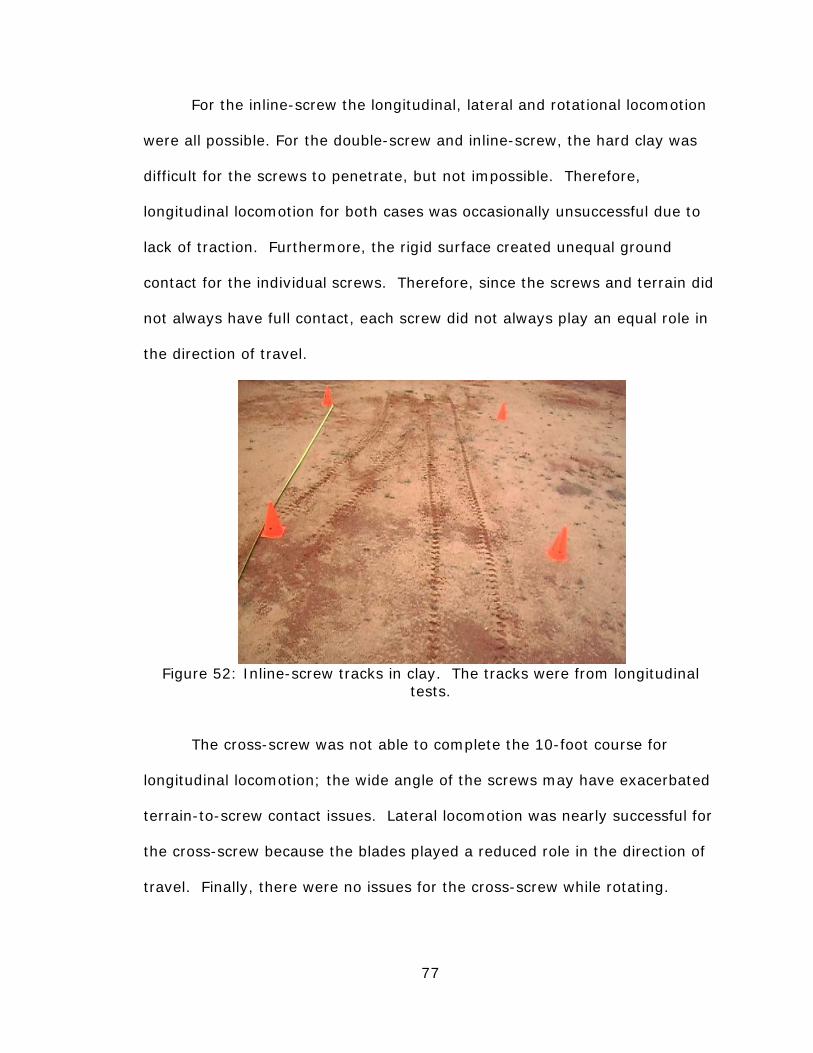
77
For the inline-screw the longitudinal, lateral and rotational locomotion
were all possible. For the double-screw and inline-screw, the hard clay was
difficult for the screws to penetrate, but not impossible. Therefore,
longitudinal locomotion for both cases was occasionally unsuccessful due to
lack of traction. Furthermore, the rigid surface created unequal ground
contact for the individual screws. Therefore, since the screws and terrain did
not always have full contact, each screw did not always play an equal role in
the direction of travel.
Figure 52: Inline-screw tracks in clay. The tracks were from longitudinal
tests.
The cross-screw was not able to complete the 10-foot course for
longitudinal locomotion; the wide angle of the screws may have exacerbated
terrain-to-screw contact issues. Lateral locomotion was nearly successful for
the cross-screw because the blades played a reduced role in the direction of
travel. Finally, there were no issues for the cross-screw while rotating.

78
The diamond-screw performed the similar to the cross-screw, except
its performance was better for lateral locomotion than the cross did for
longitudinal. In addition, since the rolling-forces, which opposed the set
direction for longitudinal locomotion, overcame the tractive-forces, the
diamond-screw moved in reverse when the switches were set to go forward.
Lastly, the diamond-screw could not complete a single rotation. When
attempting to rotate, it turned briefly and removed the top layer of loose
clay.
Figure 53: Diamond-screw rotation tracks in clay.
7.3.6 Pavement. Clearly, pavement is the least friendly surface for a
vehicle employing screw locomotion. Both the double-screw and inline-screw
failed longitudinal locomotion, because the threads had minimal traction.
Also, both configurations behaved the same for lateral locomotion because
the blades played minimal role in the path. The critical difference between
the double-screw and inline-screw was that rotation was possible for the
inline-screw. Specifically, the inline-screw proved capable of rotating about

79
its center on pavement. If a screw-vehicle operator comes across a surface
such as pavement or solid rock, they can navigate it by using a combination
of lateral and rotational locomotion.
Figure 54: The cross-screw on pavement.
The cross-screw and diamond-screw displayed similar performance on
pavement as they did on clay. However, since the pavement was more rigid
than the clay, the blades played even less of a role, and most of the motion
produced was due to rolling forces. In addition, the rigid ground created
inconsistencies in the screw-to-ground contact which exacerbated the path
deviation. In summary, the cross-screw performed equally poorly in
longitudinal and lateral locomotion and excelled in rotating. Alternatively,
the diamond-screw moved poorly and in reverse during longitudinal motion
and performed poorly during lateral and rotational locomotion. It is possible
that the cross-screw and diamond-screw could have been more effective in

80
lateral and longitudinal locomotion if the screws rotated slower, were made
of a material with better grip, such as rubber, and there was a suspension
system to allow equal ground contact between all of the screws.
A) B)
C) Figure 55: Inline-screw performance with minimal tractive-force influence
such as on pavement. A) Longitudinal (small force) B) Lateral C) Rotational
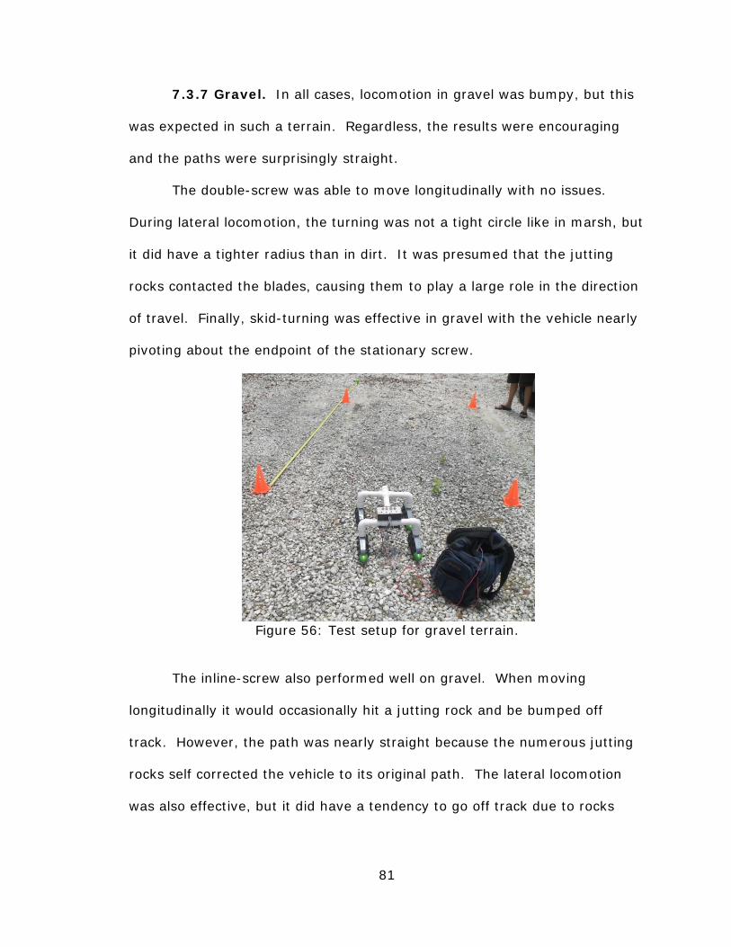
81
7.3.7 Gravel. In all cases, locomotion in gravel was bumpy, but this
was expected in such a terrain. Regardless, the results were encouraging
and the paths were surprisingly straight.
The double-screw was able to move longitudinally with no issues.
During lateral locomotion, the turning was not a tight circle like in marsh, but
it did have a tighter radius than in dirt. It was presumed that the jutting
rocks contacted the blades, causing them to play a large role in the direction
of travel. Finally, skid-turning was effective in gravel with the vehicle nearly
pivoting about the endpoint of the stationary screw.
Figure 56: Test setup for gravel terrain.
The inline-screw also performed well on gravel. When moving
longitudinally it would occasionally hit a jutting rock and be bumped off
track. However, the path was nearly straight because the numerous jutting
rocks self corrected the vehicle to its original path. The lateral locomotion
was also effective, but it did have a tendency to go off track due to rocks

82
contacting the blades. Rotation about the inline-screw’s center worked
effectively and with minimal deviation.
The cross-screw and diamond-screw were not as successful on gravel.
During longitudinal testing, the cross-screw frequently deviated from its path
and stayed off track. It was possible that since the rolling-force contributed
to the forward motion, the cross-screw was going fast enough to exacerbate
the path deviation. Again, similar to all of the terrains discussed thus far, the
cross-screw performed poorly during lateral locomotion, but rotated with
ease.
The diamond-screw produced no meaningful locomotion during
longitudinal testing in gravel. The rolling- and tractive-forces must have
been nearly equal because it exhibited paths in many directions. Lateral
locomotion was successful for the diamond-screw and less path deviation
was observed in comparison to the longitudinal cross-screw locomotion.
Finally, rotation was also successful for the diamond-screw in gravel.
Figure 57: Path from the diamond-screw rotating in gravel.

83
7.3.8 Surface of Water. From the testing on water, it was clear that
the tractive-forces dominated while the rolling-forces were negligible. In all
cases where rolling-forces were the only forces contributing to locomotion, no
locomotion resulted. Furthermore, each configuration moved in the direction
that the net tractive-forces dictated.
On top of water, the double-screw moved in a similar fashion to solid
surfaces. As in every surface, except pavement, counter-rotating the screws
moved it forward and backward. However, for the double-screw, lateral
locomotion on water resulted in turning about its center.
The inline-screw yielded interesting results on the surface of water.
When set in the longitudinal setting, the vehicle moved with ease across the
water. A unique aspect of the inline-screw in water was its limited
movement during lateral locomotion. The locomotion of the vehicle during
lateral testing appeared to be a straight, lateral path. However, the speed
was minimal to the point that there was uncertainty if it was moving due to
the screws. Clearly, forward and rotation are common means of travel in
water, so the inline-screw not being able to move laterally should not be a
setback. Fortunately, when set up for rotation, the inline-screw turned about
its center.
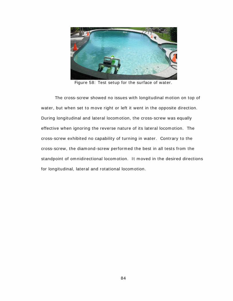
84
Figure 58: Test setup for the surface of water.
The cross-screw showed no issues with longitudinal motion on top of
water, but when set to move right or left it went in the opposite direction.
During longitudinal and lateral locomotion, the cross-screw was equally
effective when ignoring the reverse nature of its lateral locomotion. The
cross-screw exhibited no capability of turning in water. Contrary to the
cross-screw, the diamond-screw performed the best in all tests from the
standpoint of omnidirectional locomotion. It moved in the desired directions
for longitudinal, lateral and rotational locomotion.

85
A) B)
C) Figure 59: Inline-screw performance with minimal rolling-force influence such
as on water. A) Longitudinal B) Lateral (small force) C) Rotational
7.3.9 Underwater. During underwater testing, videos were taken
above the surface and below the surface of the water. The author, equipped
with a snorkel and waterproof camera, operated the test-bed and took
underwater video while an assistant took video from the surface.
For every quad-screw configuration the underwater testing showed the
same directions of locomotion as on the surface of water. As outlined in Dr.

86
Cole’s work, the only difference the depth of submersion makes is the driving
torque and thrust. In particular, the driving torque and thrust reduce as air
is introduced to the screws [14]. Therefore, it was expected that each
condition would result in similar paths as the surface of water.
Figure 60: Underwater view during testing.
Figure 61: Test setup for underwater testing.
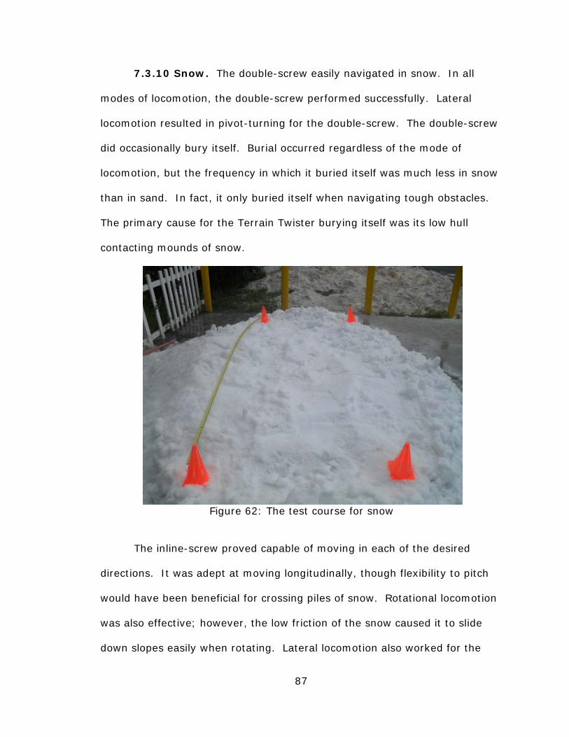
87
7.3.10 Snow. The double-screw easily navigated in snow. In all
modes of locomotion, the double-screw performed successfully. Lateral
locomotion resulted in pivot-turning for the double-screw. The double-screw
did occasionally bury itself. Burial occurred regardless of the mode of
locomotion, but the frequency in which it buried itself was much less in snow
than in sand. In fact, it only buried itself when navigating tough obstacles.
The primary cause for the Terrain Twister burying itself was its low hull
contacting mounds of snow.
Figure 62: The test course for snow
The inline-screw proved capable of moving in each of the desired
directions. It was adept at moving longitudinally, though flexibility to pitch
would have been beneficial for crossing piles of snow. Rotational locomotion
was also effective; however, the low friction of the snow caused it to slide
down slopes easily when rotating. Lateral locomotion also worked for the

88
inline-screw, but since it fully relied on rolling-forces the slick surface caused
it to slide around on the snow. Any portion of the snow that was not
perfectly level played a large influence in changing the direction of the inline-
screw when it was tested for lateral locomotion. Lastly, the inline-screw
frequently buried itself during lateral locomotion.
As anticipated, the cross-screw could not move laterally, while the
diamond-screw could not move longitudinally. Furthermore, the cross-screw
performed well longitudinally as did the diamond-screw when moving
laterally. An interesting observation was the cross-screw quickly buried itself
during rotation while the diamond-screw had no issues during rotation. It
was presumed that the minimal friction in snow was detrimental to the
rolling-forces of the cross-screw, while the cohesion in the snow was
beneficial to the tractive-forces that the diamond-screw relied on for rotation.
7.3.11 Split-Screw Tests. The split-screw was tested on a limited
number of surfaces because it was similar to a double-screw with limited
improvements. The split-screw was tested on grass, pavement, and water.
Therefore, each extreme of terrain was tested for the split-screw. That is,
the rigid-screw was tested on a rigid surface, a compliant surface and a fluid.
Testing on the split-screw demonstrated that it could not move in a straight,
lateral direction on grass. Instead, it arced like a double-screw because
there were no counteracting tractive-forces to straighten its path. On
pavement and in water, the split-screw was identical to the inline-screw with
respect to its possible directions of locomotion.

89
7.4 Turning Radius
For this study, the circle that circumscribes a screw-vehicle is defined
as its plan. The plan for a double-screw, inline-screw, cross-screw, and
diamond-screw are given in figure 63. For each configuration, a line is drawn
connecting the vertices to indicate the diameter of its plan.
Measurements were made to determine the plan-diameter of the
double-screw, inline-screw, cross-screw, and diamond-screw. Testing was
performed in marsh because visible tracks were left behind. The tracks were
used to determine the turning diameter for each configuration. Marsh was
also useful because the double-screw was able turn by pivot-turning, skid-
turning and arc-turning.
A) B)
C) D)
Figure 63: The plan and turning diameter. A) Double-screw B) Inline-screw C) Diamond-screw D) Cross-screw

90
Table 2: Turning-diameter and turning-ratio in marsh Inline-screw
Cross-screw
Diamond-screw
Steering Skid Pivot Arc Rotate Rotate Rotateturning-diameter (inches)
28 29 61 30 29 26
plan-diameter (inches)
14.5 14.5 14.5 29 29 25
turning-ratio
1.931 2 4.207 1.034 1 1.04
Double-screw
Table 2 clearly illustrates the quad-screw configurations had a 1:1
turning ratio while the double-screw had a 2:1 ratio for pivot- and skid-
turning. The data makes sense because the double-screw turns about its
end rather than its center. Figures 64 and 65 show tracks from the turning
tests.
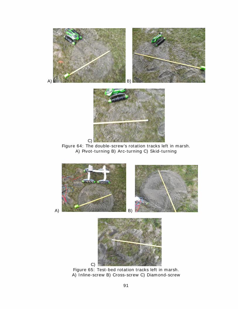
91
A) B)
C) Figure 64: The double-screw’s rotation tracks left in marsh.
A) Pivot-turning B) Arc-turning C) Skid-turning
A) B)
C) Figure 65: Test-bed rotation tracks left in marsh. A) Inline-screw B) Cross-screw C) Diamond-screw

92
7.5 Test Summary
Table 3 is a performance matrix that summarizes the three types of
locomotion. Each quad-screw configuration is rated on a scale from 0-5.
The scale was based on each configuration’s ability to move in the set
direction without deviating from their path or becoming immobilized.
• 0: No movement or the path cannot be determined
• 1: Brief motion in the set direction followed by immediate and
consistent immobilization or path deviation.
• 3: Clearly moves in the set direction with occasional
immobilization or path deviation.
• 5: Clearly and consistently moves in the set direction with no
instances of immobilization and minimal path deviation.
Table 3: Quad-screw performance matrix
Long. Lat. Rot. Long. Lat. Rot. Long. Lat. Rot. AverageSurfaceGrass 5 5 5 5 1 5 0 5 5 4Dirt 4 5 5 4 1 5 1* 4 2 3.75
Marsh 5 5 5 5 0 3 0 5 4 3.556Sand 3 4 5 3 1 5 1* 3 1 3.125Clay 2 5 5 2 1 5 1* 2 1 2.875
Gravel 5 4 5 2 1 5 0 4 5 3.444Pavement 0 5 5 1 1 5 1* 1 1 2.375
Above Water 5 0 5 5 5* 0 5 5 5 3.75Underwater 5 0 5 5 5* 0 5 5 5 3.75
Snow 5 3 4 3 0 1 0 4 5 2.778Average 3.9 3.6 4.9 3.89 0.67 3.78 1.111 4.22 3.78
Inline Cross Diamond
An asterisk indicates reversed locomotion.
Note: All values are generic units.
There are several points of interest in table 3. Namely, the inline-
screw scored the same or higher than the other configurations in every
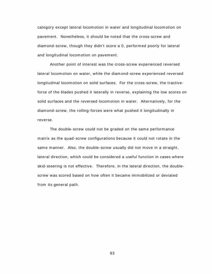
93
category except lateral locomotion in water and longitudinal locomotion on
pavement. Nonetheless, it should be noted that the cross-screw and
diamond-screw, though they didn’t score a 0, performed poorly for lateral
and longitudinal locomotion on pavement.
Another point of interest was the cross-screw experienced reversed
lateral locomotion on water, while the diamond-screw experienced reversed
longitudinal locomotion on solid surfaces. For the cross-screw, the tractive-
force of the blades pushed it laterally in reverse, explaining the low scores on
solid surfaces and the reversed locomotion in water. Alternatively, for the
diamond-screw, the rolling-forces were what pushed it longitudinally in
reverse.
The double-screw could not be graded on the same performance
matrix as the quad-screw configurations because it could not rotate in the
same manner. Also, the double-screw usually did not move in a straight,
lateral direction, which could be considered a useful function in cases where
skid-steering is not effective. Therefore, in the lateral direction, the double-
screw was scored based on how often it became immobilized or deviated
from its general path.

94
Table 4: Double-screw performance matrix
Long. Lat. SkidSurfacegrass 5 A 5 4dirt 4 A 5 3
marsh 5 P 5 4sand 3 A 4 1
dry clay 3 A 5 2gravel 5 A 5 5
pavement 0 S 5 0above water 5 P 5 5underwater - - -
snow 5 P 4 4Average 3.5 4.3 2.8
Double-Screw
S=straight, A=arc, P=pivot
Note: All values are generic units
Figure 66 shows the relationship between the longitudinal velocity of
the inline-screw and the percent the screws are slipping. The data confirms
the studies reviewed by showing cohesive terrain of low friction being optimal
for reducing slippage. From the literature, sand was characterized by being
loose and highly frictional. The dirt tested was located in Florida which can
also be characterized by a high sand content. Therefore, the loose sand and
dirt showed a relatively high slippage and low velocities. In comparison,
grass, wet marsh, and snow were described as being cohesive and low
friction surfaces. Again, grass, marsh, and snow moved the quickest and
experienced the least slippage. It should be noted that the underwater
configuration experienced greater drag and was a much heavier setup than
the above water configuration. Therefore, it was expected to experience far
greater slippage.

95
Figure 66: A graph illustrating the correlation between forward speed and
percent slip. Above water and underwater data
Percent slip =LBN` a
@TLBN
ffffffffffffffffffffffffffffffffffB100 (4)
Where:
L= Screw’s lead
N= number of blade revolutions
T= Travel distance
Figures 67, 69 and 70 are charts comparing speeds for the inline-screw,
cross-screw and diamond-screw.
0.5
1
1.5
2
2.5
3
3.5
4
0 20 40 60 80 100
Spe
ed (
Feet
/Sec
ond)
Percent Slip
Sand Dirt Grass Deep grass
Clay Snow Marsh Gravel
Above water Underwater

96
Figure 67: Longitudinal speeds for the test-bed configurations in different
terrains.
From figure 67, on loose, frictional surfaces such as sand, dirt and
gravel the cross-screw was fastest. However, in cohesive, low friction
surfaces the inline was fastest. The above observation makes sense when
considering the rolling-forces, which exist only for the cross-screw, rely on
friction, while friction works against the tractive-forces. On water, the inline
was faster because the tractive-forces were exactly in the direction of
motion. It was presumed that the cross-screw was slower than the diamond-
screw for above water tests because of the test-bed’s setup. The float
blocked the wake generated by the front-screws of the cross-screw
configuration during forward locomotion.
0
0.5
1
1.5
2
2.5
3
3.5
4
Spe
ed (
Feet
/Sec
ond)
Inline Cross Diamond
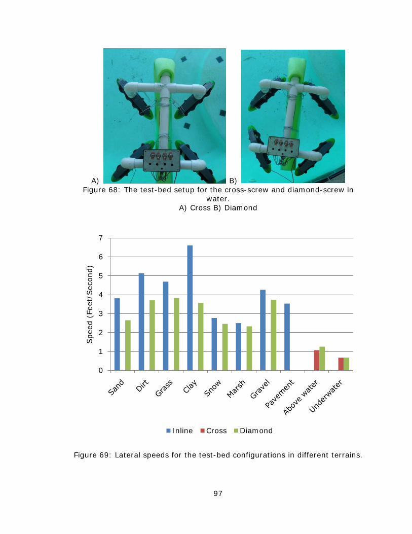
97
A) B) Figure 68: The test-bed setup for the cross-screw and diamond-screw in
water. A) Cross B) Diamond
Figure 69: Lateral speeds for the test-bed configurations in different terrains.
0
1
2
3
4
5
6
7
Spe
ed (
Feet
/Sec
ond)
Inline Cross Diamond

98
For lateral locomotion, the inline-screw was always faster than the
diamond-screw. The reason was likely because the rolling-forces of the
inline-screw directly contributed to its locomotion. Appendix D shows the
screws used for the test-bed roll laterally further per revolution than they
screw forward. Finally, in water the cross-screw and diamond-screw
travelled at nearly the same lateral speed because the test-bed’s float
blocked screws in both configurations.
Figure 70: Rotational speeds for the test-bed configurations in different
terrains.
The cross-screw was always fastest because the rolling-forces directly
contributed to rotation. Again, water was an exception because the
importance of the rolling-forces and tractive-forces are flipped. The
diamond-screw was fastest in water for rotation because its tractive-forces
were exactly in the direction of rotation.
0
0.2
0.4
0.6
0.8
1
1.2
Spe
ed (
Rot
atio
ns/S
econ
d)
Inline Cross Diamond

99
CHAPTER 8: CONCLUSIONS
In this study, a thorough investigation of the double-screw was
performed. From the research, it was determined that improvements could
be made from the standpoint of omnidirectional locomotion. In particular,
the double-screw could not follow a straight, lateral path, except on the most
rigid of terrains, and could not turn about its center unless on water.
Furthermore, the double-screw had only limited potential for turning on
pavement.
A number of solutions were given an initial investigation, and three
were selected for a full study of omnidirectional locomotion. Specifically, the
inline-screw, the cross-screw, and the diamond-screw were selected for this
study. The study consisted of a force-vector analysis, a mobility study, and
maximum speed tests.
The mobility studies showed the inline-screw was the most versatile
and predictable configuration compared to the cross-screw and diamond-
screw. Basically, the inline-screw was fully omnidirectional on all surfaces
except pavement and water. Nonetheless the inline-screw was able to
navigate pavement and water by rotating about its center. On the contrary,
the cross- and diamond-screws exhibited limited lateral or longitudinal

100
capabilities, respectively. Furthermore, the direction of locomotion for the
cross-screw and diamond-screw varied depending on the surface.
The vector analyses in this study verified all of the mobility test
results. Therefore, it can safely be confirmed that the inline-screw was the
most versatile of the three test-bed configurations. In addition, according to
the vector analyses, the inline-screw is the only configuration that
experiences no inherent indeterminate or impure locomotion. Furthermore,
the inline-screw resolved issues of the double-screw by allowing for straight,
lateral locomotion and rotation about its center on all surfaces. A distinct
advantage is the potential to maneuver over paved surfaces through a
combination of lateral and rotational locomotion.
Each of the quad-screw configurations that were tested demonstrated
a strong point. In water, the diamond-screw was clearly the optimal
configuration from the standpoint of omnidirectional locomotion, because it
was the only configuration capable of locomotion in all directions.
Alternatively, the cross-screw proved to be the fastest in highly frictional soil
such as sand or dirt and was the fastest on gravel. All in all, the inline-quad-
screw, which is proposed for the first time in this thesis, represents the best
overall versatility and performance in an omnidirectional screw-drive.

101
LIST OF REFERENCES
[1] Neumeyer, M. J., & Jones, B. D. (1965). Marsh screw amphibian. Journal of Terramechanics, 2(4), 83-88.
[2] Fales, W. K., Amick, D. W., & Schreiner, B. G. (1972). The riverine utility
craft (RUC). Journal of Terramechanics, 8(3), 23-38. [3] Dugoff, H., & Ehrlich, I. R. (1967). Model tests of buoyant screw rotor
configurations. Journal of Terramechanics, 4(3), 9-22. [4] 1926 Fordson Snowmobile Retrieved October 13, 2010, from
http://commons.wikimedia.org/wiki/File:1926_Fordson_snowmobile.jpg
[5] Messenger, B., & Mullins, P. (2003). The ultimate all-terrain vehicle.
Diesel Progress International Edition, 22(1), 24-25. [6] Leonov, V., & Kenlip, O. (2005). In Mattel I. (Ed.), Screw drive vehicle.
California: 6,966,807. [7] Hara, M., Satomura, S., Fukushima, H., Kamegawa, T., Igarashi, H., &
Matsuno, F. (2007). Control of a snake-like robot using the screw drive mechanism. 2007 IEEE International Conference on Robotics and Automation, 6.
[8] Knight, S. J., Rush, E. S., & Stinson, B. G. (1965). Trafficability tests with
marsh screw amphibian. Journal of Terramechanics, 2(4), 31-50. [9] Schreiner, B. G., Smith, R. P., & Green, C. E. (1970). Performance of
riverine utility craft (RUC) in riverine environments (Technical No. M-70-5). Vicksburg, Mississippi: U.S. Army Engineer Waterways Experiment Station.
[10] Bauxite residue management. (2009). Retrieved September, 17, 2010,
from http://www.residuesolutions.com.au/Default.aspx [11] Kocak, D. M., Neely, J. W., Holt, J., & Miyake, M. (1999). A specialized
ROV for cleaning groundwater recharge basins. Conference Proceedings, , 2 567-79.
102
[12] Johannessen, B. O., Jensen, H., Laurie, S., & Lorenzo, T. (1996). Mechanical oil recovery in ice infested waters (MORICE)-phase 1 (Technical No. STF22 F96225). Trondheim, Norway: Sintef Civil and Environmental Engineering.
[13] Perez, M. L. (1997). A cost-effective multi-terrain autonomous vehicle
for hostile environments. Proceedings of the American Nuclear Society Seventh Topical Meeting on Robotics and Remote Systems, , 1 352-9.
[14] Cole, B. N. (1961). Inquiry into amphibious screw traction. Institution of
Mechanical Engineers -- Proceedings, 175(19), 919-940. [15] Gorton, J. V. (1966). New amphibious vehicle programs -- 2. Naval
Engineers Journal, 77(3), 407-412. [16] Kusmir, K. C. (1969). Land vehicle propulsion. Illinois: US Patent
3420326.

103
BIBLIOGRAPHY
Bakker, J. J. d. (1967). Amphibious vehicle. Netherlands: Patent 3,333,563. Barriol, R., Goutierre, A., Longuemard, J. P., & Valls, A. (1985). Study of
starting of an archimedes' screw which is pressing on the sea bottom and propelling a submarine vehicle. Revue De Physique Appliquee, 20(12), 837-44.
Becker, A. C. (1962). Snow traction unit. California: US Patent3059711. Bertrand, P. A. (1965). Tractor vehicle. Canada: Patent 3224407. Breen, F. P. (1928). Spiral drive device. Massachussets: US Patent 1685702. Chhabra, N. K. (1997). Hybrid Tracked/Swedish locomotion system for a land
operated robot vehicle. University of South Florida). Code, S. M. (1927). Amphibious vehicle. Illinois: US Patent 1646611. Cutting, L. A., & Horne, J. C. (1955). Rotary hull vehicle. California: US
Patent 2706958. Foster, C. R., & Knight, S. J. (1957). Vehicle mobility on soft soils. Military
Engineer, 49(328), 92-94. Garate, J. J. C. (1966). Amphibious vehicles. Spain: 3250239. Hart, D. S., Beller, L. D., & White, R. L. (1993). In Crude Tool Works (Ed.),
Amphibious vehicle. Alaska: US Patent 5203273. Hollis, O. A. (1913). Tractor. Delaware: US Patent 1069875. Komoto, M., & Nakamura, M. (1984). Amphibian vehicle. Japan: Patent
4476948. Mainguy, D. N. (1968). In Mainguy D. N., Andrews J. S.(Eds.), Amphibious
vehicle. Alabama: US Patent 3397668.

104
Norton, R. L. (2006). Screws and fasteners. In M. J. Horton, O'Brien. V., D. A. George & S. Disanno (Eds.), Machine design an integrated approach (3rd ed., pp. 811). Upper Saddle River, NJ: Pearson Prentice Hall.
Poole, N. M. (1970). Submersible pipe laying barges. California: US Patent
3514962 Waquet, B. E. L. M. (1972). Amphibious vehicle with rotating floats. France:
Patent 3682127. Zhaung, J., Wang, Z., & Liu, J. (1990). Study on the dynamic characteristics
of wheeled vehicles on sand. Winter Annual Meeting of the American Society of Mechanical Engineers, November 25, 1990 - November 30, , 108 211-217.
Zimmerman, H. P., Jr. (1968). Steering device for amphibious vehicle.
Michigan: US Patent 3395671.

105
APPENDICES

106
Appendix A: S-Diamond-Screw Force-Vectors
A) B)
C) D) Figure A1: Four symmetric screw rotations for the S-diamond-screw. A) Longitudinal (roll dominated) B) Rotational (impure skew motion)
C) Lateral D) Longitudinal (traction dominated)

107
Appendix B: S-Cross-Screw Force-Vectors
A) B)
C) D) Figure B1: Four symmetric screw rotations for the S-cross-screw.
A) Longitudinal (roll dominated) B) Lateral C) Rotational (impure skew motion) D) Longitudinal (traction dominated)

108
Appendix C: Mirrored-Test-Bed Force-Vectors
A) B)
C) D)
Figure C1: Four symmetric screw rotations for the mirrored inline-screw. A) Longitudinal B) Lateral
C) Rotational (indeterminate rotation direction) D) No locomotion

109
Appendix C: (Continued)
A) B)
C) D) Figure C2: Four symmetric screw rotations for the mirrored-diamond-screw.
A) Longitudinal B) Lateral (left or right is indeterminate) C) Rotational D) No locomotion

110
Appendix C: (Continued)
A) B)
C) D) Figure C3: Four symmetric screw rotations for the mirrored-cross-screw.
A) Longitudinal (forward or reverse is indeterminate) B) Lateral C) Rotational D) No locomotion

111
Appendix D: Terrain Twister Screw Calculations
The screw for the Terrain Twister was unique because the drum was
shaped like a barrel with the middle of a larger diameter than the ends. The
blade-height varied so most of the tips could contact level ground. The
minimum and maximum values for each measurement are located in Table
A1.
Table A1: Terrain Twister screw measurements Ends Center
Drum-Diameter 2.25 2.5
Length (inches) 9.125 9.125
Lead (inches) 5 5
Blade-Height (inches)
0.313 0.375
Calculations were made using the minimum and maximum values.
The values that were furthest from being ideal, according to the reviewed
research, were used to be conservative. The formula used to calculate the
helix-angle was:
φ =tan@1 LπB D +hb cffffffffffffffffffffffffffffffffff
hlj
imkB
180πfffffffffffff (5)
For one revolution, the distance travelled due to rolling is equal to the
circumference of the outer diameter of the screw. Alternatively, the distance
travelled in one revolution due to screwing is equal to the screw’s lead.

112
Appendix D: (Continued)
Figure D1: The Terrain Twister’s major diameter and lead.
Circumference = πBDm (6)
Where:
Dm= major diameter
Since the travel distance, T, for rolling is the same as the
circumference:
T = πB2.875 inches =9.03 inches (7)
The screws that were used had a lead of 5-inches. Therefore, a
vehicle using those screws will travel 1.8 times further per revolution for
rolling compared to screwing.

ABOUT THE AUTHOR
Jon Timothy Freeberg was born in Arcadia, California in 1984, and in 2007 he
earned a Bachelor of Science in Mechanical Engineering at the University of
South Florida. For two years he worked as a manufacturing engineer intern
at Conmed Linvatec in Largo, Florida where he worked in the shaver blade
factory. His responsibilities, among others, included validating packaging
equipment, investigating pyrometers on induction bonder equipment, and
introducing a new process of lubricating arthroscopic shaver blades. In
2009, he returned to the University of South Florida to pursue his Master of
Science degree in Mechanical Engineering.
Related Documents