A standardized approach to deal with firewall and mobility policies in the IoT Sylvain Kubler a,* , Kary Fr¨ amling a , Andrea Buda a a Alto University, School of Science and Technology P.O. Box 15500, FI-00076 Aalto, Finland Abstract Internet of Things (IoT) is intended to provide a network where information flows could easily be set up between any kinds of products, devices, users and information systems in general. This vision is getting closer to become real due to the continuous development of new information system concepts and technologies. Nonetheless, this new reality requires special attention on particular aspects of the IoT such as security and mobility. First, people and companies want to secure their assets/data using firewalls, which inevitably leads to a challenging conflict between data security and usability. Second, products are becoming increasingly mobile, operating in environments where it can be difficult to contact them directly using their IP address (e.g., due to the presence of NAT or to access restrictions). It might therefore be necessary in some IoT applications to enable two-way communications through any type of firewall, e.g. to enable real-time control and maintenance. Quantum Lifecycle Management (QLM) messaging standards have been designed to provide generic and standardized application-level interfaces for the IoT that make it possible, among other things, to achieve such two-way communication. This paper provides a high-level description of QLM messaging standards with a particular focus on this QLM feature, along with proofs-of-concept through real-life implementations in building and automotive domains. Keywords: Internet of things, Firewall, Mobile computing, Product Lifecycle Management, Piggy backing 1. Introduction In the so-called Internet of Things (IoT) and Cyber Physical Systems (CPS), mobile users and objects will be able to dynamically discover and impromptu interact with heterogeneous computing, physical resources, as well as virtual data and environments [1, 2, 3, 4]. These visions are getting closer to become real due to the every day increase of concepts and technologies such as sensor hardware/firmware, semantic, cloud, data modeling, storing, reasoning, etc. [5, 6]. Billions of devices are connected to the Internet and it is predicted that there will be 50-100 billions by 2020 [7]. As stated by Perera et al. [8], standardization is crucial in the IoT paradigm because it increases interoperability and extendibility, but so far there is still a real need for sufficiently generic and generally applicable application-level IoT messaging standards. This is all the more true following the interpretation of the IoT given in [9], where the IoT is used in the sense of “a generic information system for accessing and synchronizing any kind of product-related information, mainly over the Internet.” In this interpretation, the focus is given to the entire product lifecycle, in which the product operates through numerous business areas [10, 11]. Within this context, the primary challenge is to provide standardized interfaces to enable complex business procedures and seamless information exchange among all product stakeholders and involved systems [12]. The design of such interfaces are an essential step to enhance product lifecycle management (PLM), while enabling the creation of a true IoT [13]. However, no proper agreement on a common standard for IoT data exchange between organizations has yet been reached or even proposed. Quantum Lifecycle Management (QLM) standards have been developed as a standard that would fulfill the main IoT requirements [14]. A fundamental requirement is to enable Peer-to-Peer (P2P) communication for all devices, even in mobile or secured environments. * Corresponding author Email addresses: [email protected] (Sylvain Kubler), [email protected] (Kary Fr¨ amling), [email protected] (Andrea Buda) Preprint submitted to Pervasive and Mobile Computing September 24, 2014

Welcome message from author
This document is posted to help you gain knowledge. Please leave a comment to let me know what you think about it! Share it to your friends and learn new things together.
Transcript
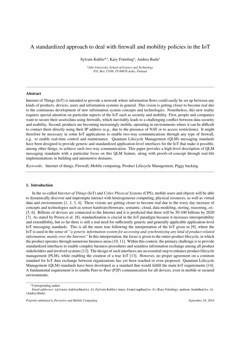
A standardized approach to deal with firewall and mobility policies in the IoT
Sylvain Kublera,∗, Kary Framlinga, Andrea Budaa
aAlto University, School of Science and Technology
P.O. Box 15500, FI-00076 Aalto, Finland
Abstract
Internet of Things (IoT) is intended to provide a network where information flows could easily be set up between any
kinds of products, devices, users and information systems in general. This vision is getting closer to become real due
to the continuous development of new information system concepts and technologies. Nonetheless, this new reality
requires special attention on particular aspects of the IoT such as security and mobility. First, people and companies
want to secure their assets/data using firewalls, which inevitably leads to a challenging conflict between data security
and usability. Second, products are becoming increasingly mobile, operating in environments where it can be difficult
to contact them directly using their IP address (e.g., due to the presence of NAT or to access restrictions). It might
therefore be necessary in some IoT applications to enable two-way communications through any type of firewall,
e.g. to enable real-time control and maintenance. Quantum Lifecycle Management (QLM) messaging standards
have been designed to provide generic and standardized application-level interfaces for the IoT that make it possible,
among other things, to achieve such two-way communication. This paper provides a high-level description of QLM
messaging standards with a particular focus on this QLM feature, along with proofs-of-concept through real-life
implementations in building and automotive domains.
Keywords: Internet of things, Firewall, Mobile computing, Product Lifecycle Management, Piggy backing
1. Introduction
In the so-called Internet of Things (IoT) and Cyber Physical Systems (CPS), mobile users and objects will be able
to dynamically discover and impromptu interact with heterogeneous computing, physical resources, as well as virtual
data and environments [1, 2, 3, 4]. These visions are getting closer to become real due to the every day increase of
concepts and technologies such as sensor hardware/firmware, semantic, cloud, data modeling, storing, reasoning, etc.
[5, 6]. Billions of devices are connected to the Internet and it is predicted that there will be 50-100 billions by 2020
[7]. As stated by Perera et al. [8], standardization is crucial in the IoT paradigm because it increases interoperability
and extendibility, but so far there is still a real need for sufficiently generic and generally applicable application-level
IoT messaging standards. This is all the more true following the interpretation of the IoT given in [9], where the
IoT is used in the sense of “a generic information system for accessing and synchronizing any kind of product-related
information, mainly over the Internet.” In this interpretation, the focus is given to the entire product lifecycle, in which
the product operates through numerous business areas [10, 11]. Within this context, the primary challenge is to provide
standardized interfaces to enable complex business procedures and seamless information exchange among all product
stakeholders and involved systems [12]. The design of such interfaces are an essential step to enhance product lifecycle
management (PLM), while enabling the creation of a true IoT [13]. However, no proper agreement on a common
standard for IoT data exchange between organizations has yet been reached or even proposed. Quantum Lifecycle
Management (QLM) standards have been developed as a standard that would fulfill the main IoT requirements [14].
A fundamental requirement is to enable Peer-to-Peer (P2P) communication for all devices, even in mobile or secured
environments.
∗Corresponding author
Email addresses: [email protected] (Sylvain Kubler), [email protected] (Kary Framling), [email protected]
(Andrea Buda)
Preprint submitted to Pervasive and Mobile Computing September 24, 2014
The proliferation of mobile and pervasive computing devices over the past decade has made host and service
mobility on the Internet a significant issue. Delivering data to a mobile host across a network address change (e.g., a
NAT router) without disrupting existing connections remains a central challenge [15, 16]. To compound this problem,
people take proactive measures to ensure the security, confidentiality, and integrity of their assets/data using firewall
and proxy systems [17, 18, 19] that inevitably leads to a challenging conflict between data security and usability;
security making it more challenging to implement new services, while usability is required in order to achieve user
acceptation of those services [20, 21]. This is particularly true considering the entire product lifecycle since product-
related data is a valuable resource for companies and should not be seen by other organizations [24]. Considering
environments with firewall and mobility policies, it might be useful to allow information sharing in a P2P fashion
despite the presence of firewalls, NATs, or similar systems (e.g., when developing real-time control or predictive
maintenance services in the IoT [11, 22]).
The QLM messaging standards propose a set of interfaces that enable, among other things, real-time communica-
tions as well as two-way communications with nodes located behind firewall/NAT systems. This property exploits the
possibility to place further requests as a part of a response to an earlier request over the same connection. This concept
is commonly referred to as “piggy backing” [23]. Section 2 provides the IoT background from a PLM perspective to
understand the general interests of introducing such a new IoT standard. Section 3 provides a high-level description
of the QLM specifications, followed by section 4 that presents in greater detail the QLM piggy backing property.
Two real-life applications implemented in the contexts of home automation and car diagnostics, each one dealing with
different security and mobility aspects, are presented in Section 5; conclusions follow.
2. IoT background from a PLM perspective
Product lifecycle management (PLM), is commonly understood to be a strategic approach that incorporates the
management of data associated with products of a particular type, as well as the business processes that surround it
[24]. These product definition data typically consist of detailed specifications, user manuals, computer aided design
(CAD) drawings, manufacturing instructions, service manuals, disposal and recycling instructions and so forth. For
such traditional PLM, the product information generation process seems to end after production. When the product
enters actual use, PLM mainly signifies providing access to the existing information but hardly any new information
is generated about the products. This is, perhaps, a reflection of the point of view of the manufacturing industry that
tends to see PLM mainly as a distributed knowledge management task of the “extended enterprise” [25] that created
the product. With this view of PLM, there has been only slight interest in how the customer uses each individual
product, or in how that product has behaved.
Inter-organizational data exchange is a pre-requisite for any kind of PLM in the context of the extended enterprise.
In PLM, it usually signifies the transfer of electronic documents or business data from one computer system to another,
i.e. from one trading partner to another without human intervention. Data exchange requires some kind of physical
media for transmitting the data from one system to the other, a protocol that allows determining what a system should
send when and where, one or more interfaces that send and/or receive data, and a semantic layer for understanding the
data in a uniform way. The further up we go on the “protocol stack” towards the semantic level, the more challenging
it is to create data exchange standards that are unambiguous, while providing a sufficient power of expression. When
dealing with product instance-enabled PLM, the need for adequate standards becomes even more flagrant due to the
presence of people, embedded devices, and mobile devices that need to communicate with each other in ad hoc and
context-dependent ways. Concepts such as “Product Agents” and “Intelligent Products” [26, 27] have been proposed
as solutions for enabling such item- or instance-enabled PLM, as well as the IoT.
Such concepts were the cornerstones of the product instance-enabled PLM solutions developed in the PROMISE
EU FP6 project1. QLM standards emerged out of this project in which real-life industrial applications required the
collection and management of product instance-level information for many domains involving heavy and personal
vehicles, household equipment, phone switches, etc. Information such as sensor readings, alarms, assembly, disas-
sembly, shipping event, and other information related to the entire product lifecycle needed to be exchanged between
several organizations. The project consortium investigated potential messaging standards that would provide the kind
1http://promise-innovation.com
2
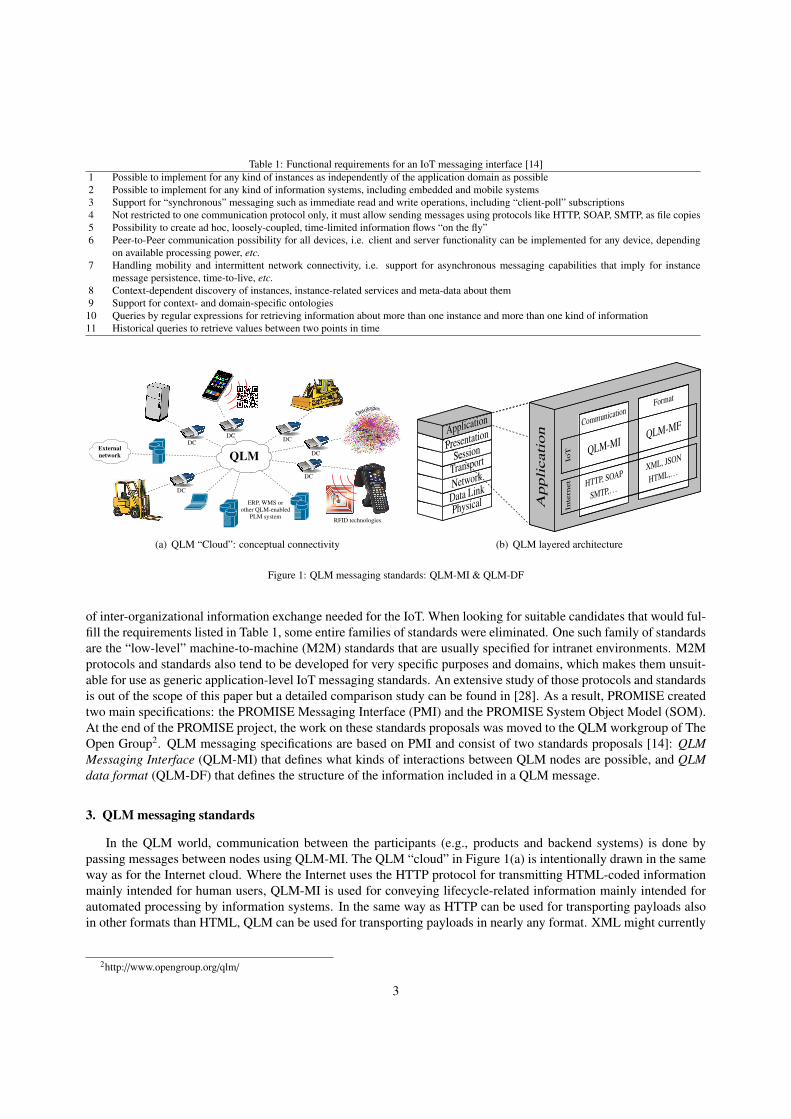
Table 1: Functional requirements for an IoT messaging interface [14]
1 Possible to implement for any kind of instances as independently of the application domain as possible
2 Possible to implement for any kind of information systems, including embedded and mobile systems
3 Support for “synchronous” messaging such as immediate read and write operations, including “client-poll” subscriptions
4 Not restricted to one communication protocol only, it must allow sending messages using protocols like HTTP, SOAP, SMTP, as file copies
5 Possibility to create ad hoc, loosely-coupled, time-limited information flows “on the fly”
6 Peer-to-Peer communication possibility for all devices, i.e. client and server functionality can be implemented for any device, depending
on available processing power, etc.
7 Handling mobility and intermittent network connectivity, i.e. support for asynchronous messaging capabilities that imply for instance
message persistence, time-to-live, etc.
8 Context-dependent discovery of instances, instance-related services and meta-data about them
9 Support for context- and domain-specific ontologies
10 Queries by regular expressions for retrieving information about more than one instance and more than one kind of information
11 Historical queries to retrieve values between two points in time
RFID technologies
Ontologies
External
network
ERP, WMS orother QLM-enabled
PLM system
QLM
DC
DC
DCDC
DC
DC
DC : Device controller(a) QLM “Cloud”: conceptual connectivity
PhysicalData LinkNetworkTransportSessionPresentationApplication
Ap
pli
cati
on
CommunicationFormat
QLM-MIQLM-MF
HTTP, SOAP
SMTP,. . .
XML, JSON
HTML,. . .
IoT
Inte
rnet
(b) QLM layered architecture
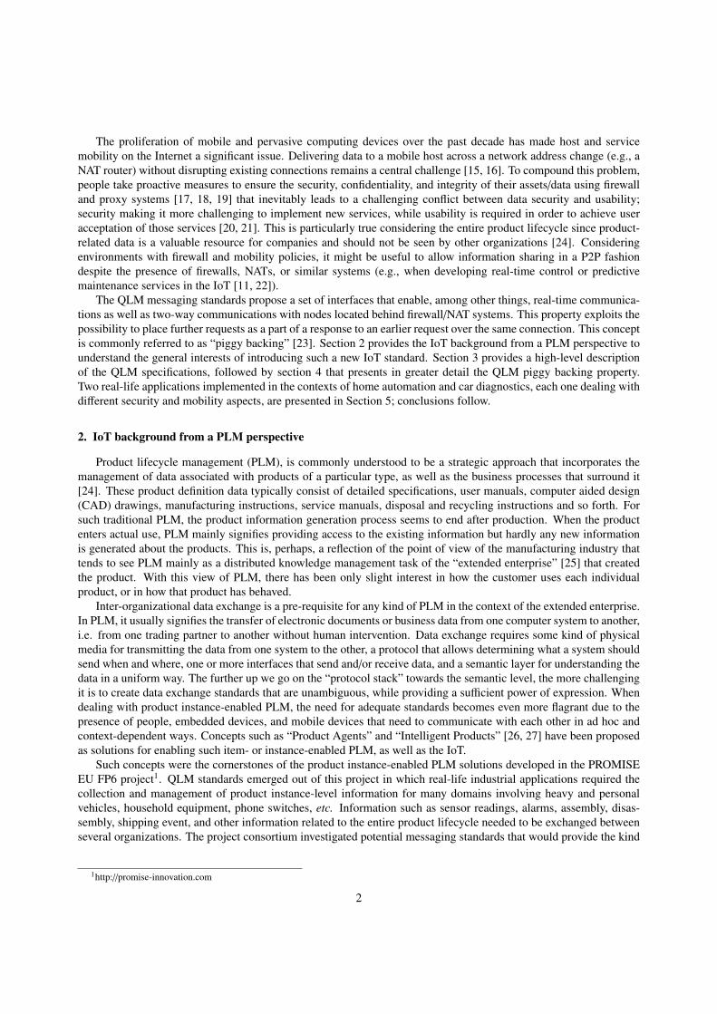
Figure 1: QLM messaging standards: QLM-MI & QLM-DF
of inter-organizational information exchange needed for the IoT. When looking for suitable candidates that would ful-
fill the requirements listed in Table 1, some entire families of standards were eliminated. One such family of standards
are the “low-level” machine-to-machine (M2M) standards that are usually specified for intranet environments. M2M
protocols and standards also tend to be developed for very specific purposes and domains, which makes them unsuit-
able for use as generic application-level IoT messaging standards. An extensive study of those protocols and standards
is out of the scope of this paper but a detailed comparison study can be found in [28]. As a result, PROMISE created
two main specifications: the PROMISE Messaging Interface (PMI) and the PROMISE System Object Model (SOM).
At the end of the PROMISE project, the work on these standards proposals was moved to the QLM workgroup of The
Open Group2. QLM messaging specifications are based on PMI and consist of two standards proposals [14]: QLM
Messaging Interface (QLM-MI) that defines what kinds of interactions between QLM nodes are possible, and QLM
data format (QLM-DF) that defines the structure of the information included in a QLM message.
3. QLM messaging standards
In the QLM world, communication between the participants (e.g., products and backend systems) is done by
passing messages between nodes using QLM-MI. The QLM “cloud” in Figure 1(a) is intentionally drawn in the same
way as for the Internet cloud. Where the Internet uses the HTTP protocol for transmitting HTML-coded information
mainly intended for human users, QLM-MI is used for conveying lifecycle-related information mainly intended for
automated processing by information systems. In the same way as HTTP can be used for transporting payloads also
in other formats than HTML, QLM can be used for transporting payloads in nearly any format. XML might currently
2http://www.opengroup.org/qlm/
3
1 <q lm:E nve lope xmlns =”QLMmi . xsd ” v e r s i o n =” 1 . 0 ” t t l =” 0 . 0 ”>
2 <q l m : r e a d msgformat =”QLMdf . xsd ”>
3 <msg>
4 <O b j e c t s xmlns =”QLMdf . xsd ”>
5 <O b j e c t t y p e =” F r i d g e ”>
6 <i d>Smartfridge2334101</ i d>
7 <I n f o I t e m name=” D o o r s t a t u s ”></ I n f o I t e m>
8 <I n f o I t e m name=” T h e r m o s t a t ”></ I n f o I t e m>
9 </ O b j e c t>
10 </ O b j e c t s>
11 </ msg>
12 </ q l m : r e a d>
13 </ q lm:E nve lope>
Generic Object tree
Objects
Object Object Object . . .
InfoItem InfoItem Object . . .
MetaData Value Value . . .
InfoItem InfoItem . . .
QLM-DF ➙
QLM-MI
QLM-MI
Figure 2: QLM Data Format: generic “Object” tree and example of a QLM message relying on that tree
be the most common text-based payload format due to its flexibility that provides more opportunities for complex data
structures [8], but others such as JSON, CSV can also be used (see Figure 1(b)). QLM-DF partly fulfills the same role
in the IoT as HTML does for the Internet, meaning that QLM-DF is the content description model for things in the
IoT. Information encoded using QLM-DF can be transported also by practically any information exchange protocol,
such as JMS, WSDL/SOAP, or ebXML Messaging Services (see Figure 1(b)).
In short, QLM-MI and QLM-DF are independent entities that reside in the Application layer of the OSI model, as
illustrated in Figure 1(b), where QLM-MI is specified as the Communication level and QLM-DF is specified as the
Format level. These two standards are respectively introduced in sections 3.1 and 3.2.
3.1. QLM data format (QLM-DF)
QLM-DF is specified as a simple ontology using XML Schema, which is generic enough for representing “any”
object and information that is needed for information exchange in the IoT. It is intentionally defined in a similar way
as data structures in object-oriented programming. It is structured as a hierarchy with an “Objects” element as its
top element. The “Objects” element can contain any number of “Object” sub-elements. Figure 2 gives insight into
both the generic hierarchy/object tree and an example of a QLM message whose structure respects this object tree. In
this example, a unique object of type Fridge (see row 5 of the XML message) is considered. “Object” elements can
have any number of properties, referred to as InfoItems, as well as “Object” sub-elements. In our example, the Object
Fridge has two InfoItems named Door status and Thermostat (see rows 7 and 8). The resulting Object tree can
contain any number of levels. Every Object has a compulsory sub-element called “id” that identifies the Object (see
row 6). The “id” should preferably be globally unique or at least unique for the specific application, domain, or
network of the involved organizations.
In object-oriented programming, objects are aware of each other both by object containment hierarchies and by
reference or pointers. In QLM-DF, such object references are made by using the Object “id” element. However, in
the IoT, the “id” does not refer to a specific memory location but to an IoT object whose information may even be
spread over several information systems and organizations. Different methods and systems have been proposed for the
discovery of such distributed information (e.g., in [29]). The simplest mechanism is to include a URL in the identifier
itself as proposed by Huvio et al. [9], and then to retrieve the information by object linking as proposed by Framling
et al. [30]. New methods are still being developed for solving this issue, which are out of the scope of this paper.
3.2. QLM messaging interface (QLM-MI)
QLM-MI has been defined to meet numerous IoT requirements listed in Table 1. A defining characteristic of QLM-
MI is that QLM nodes may act both as a “server” and as a “client”, and therefore communicate directly with each
other or with back-end servers in a P2P manner. Typical examples of exchanged data are sensor readings, lifecycle
events, requests for historical data, notifications, etc. The main properties of QLM-MI are listed in Table 2, among
which stand out fundamental ones. First, QLM-MI messages are “protocol agnostic” (see property 1), so they can be
exchanged using HTTP, SOAP, SMTP, FTP or similar protocols. The most appropriate protocol to use depends on
the application and also the security mechanisms of the protocols. This non-dependency on specific communication
protocols makes QLM different from many (or most) other potential IoT messaging standards. Second, three basic but
4
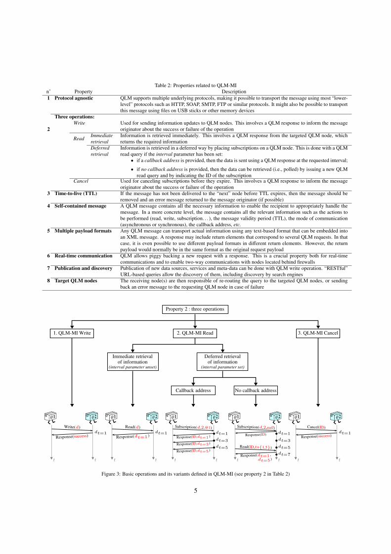
Table 2: Properties related to QLM-MI
n˚ Property Description
1 Protocol agnostic QLM supports multiple underlying protocols, making it possible to transport the message using most “lower-
level” protocols such as HTTP, SOAP, SMTP, FTP or similar protocols. It might also be possible to transport
this message using files on USB sticks or other memory devices
2
Three operations:
Write Used for sending information updates to QLM nodes. This involves a QLM response to inform the message
originator about the success or failure of the operation
ReadImmediate
retrieval
Information is retrieved immediately. This involves a QLM response from the targeted QLM node, which
returns the required information
Deferred
retrieval
Information is retrieved in a deferred way by placing subscriptions on a QLM node. This is done with a QLM
read query if the interval parameter has been set:
• if a callback address is provided, then the data is sent using a QLM response at the requested interval;
• if no callback address is provided, then the data can be retrieved (i.e., polled) by issuing a new QLM
read query and by indicating the ID of the subscriptionCancel Used for canceling subscriptions before they expire. This involves a QLM response to inform the message
originator about the success or failure of the operation
3 Time-to-live (TTL) If the message has not been delivered to the “next” node before TTL expires, then the message should be
removed and an error message returned to the message originator (if possible)
4 Self-contained message A QLM message contains all the necessary information to enable the recipient to appropriately handle the
message. In a more concrete level, the message contains all the relevant information such as the actions to
be performed (read, write, subscription. . . ), the message validity period (TTL), the mode of communication
(asynchronous or synchronous), the callback address, etc.
5 Multiple payload formats Any QLM message can transport actual information using any text-based format that can be embedded into
an XML message. A response may include return elements that correspond to several QLM requests. In that
case, it is even possible to use different payload formats in different return elements. However, the return
payload would normally be in the same format as the original request payload
6 Real-time communication QLM allows piggy backing a new request with a response. This is a crucial property both for real-time
communications and to enable two-way communications with nodes located behind firewalls
7 Publication and discovery Publication of new data sources, services and meta-data can be done with QLM write operation. “RESTful”
URL-based queries allow the discovery of them, including discovery by search engines
8 Target QLM nodes The receiving node(s) are then responsible of re-routing the query to the targeted QLM nodes, or sending
back an error message to the requesting QLM node in case of failure
Property 2 : three operations
1. QLM-MI Write 2. QLM-MI Read
Immediate retrievalof information
(interval parameter unset)
Deferred retrievalof information
(interval parameter set)
Callback address No callback address
3. QLM-MI Cancel
@1.
@2.
t t
Write(d)
Response(success)dt=1
@1.
@2.
t t
Read(d)
Response(dt=1)dt=1
@1.
@2.
t t
Subscription(d,2,@1)
Response(ID,dt=1 )dt=1
Response(ID,dt=3 )dt=3
Response(ID,dt=5 )dt=5
@1.
@2.
t t
Subscription(d,2,null)
Response(ID)dt=1
dt=3
dt=5
dt=7
Read(ID,t={1,5})
Response(dt=1 ,
dt=5)
@1.
@2.
t t
Cancel(ID)
Response(success)dt=1
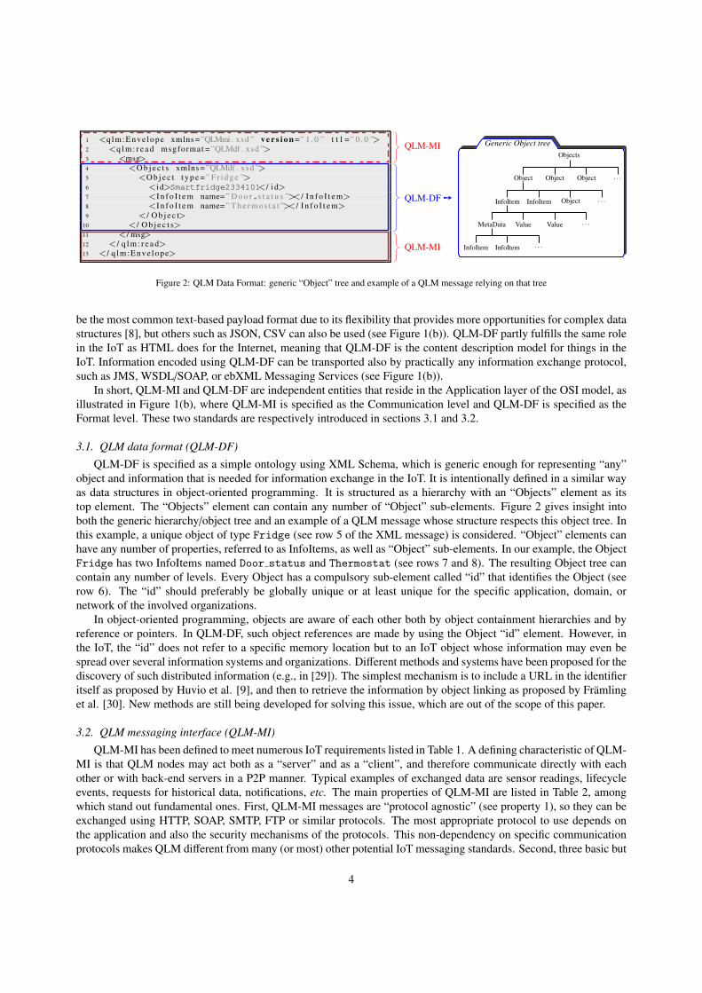
Figure 3: Basic operations and its variants defined in QLM-MI (see property 2 in Table 2)
5

fundamental operations are defined in QLM-MI (see property 2). Figure 3 illustrates these operations and variants.
QLM-MI Write is a basic update operation to modify one or several InfoItem values. Figure 3 illustrates such an
operation, in which:
• a node denoted by @1 updates InfoItem d at t = 1 on a node denoted by @2, which then returns a success
response.
Similarly, an Immediate retrieval of information is a basic QLM-MI read operation to retrieve one or several InfoItems,
as illustrated in Figure 3, in which:
• node @1 retrieved InfoItem d on node @2 at t = 1, denoted by dt=1.
The Deferred retrieval of information, also referred to as subscription mechanism, is a cornerstone of QLM-MI. As
described in Table 2 and illustrated in Figure 3, two types of subscriptions are are available:
• with callback address: in Figure 3, @1 subscribes to InfoItem d to @2, providing its address as callback with
an interval of 2s3. Then, every 2s, both the current InfoItem value d and the subscription ID is sent by @2 to
@1, i.e. at t = 1, 3, 5;
• without callback address: @1 subscribes to InfoItem d to @2 with an interval of 2s but without providing its
address as callback (denoted by null in Figure 3). @1 first receives a response with the ID of the subscription,
and @2 memorizes d values every 2s. Thus, @1 may request at any time one or several historical values with
a read request including the subscription ID, as shown in Figure 3 where @1 requests for values memorized at
t = 1 and 5 (denoted by “Read(ID,t={1, 5})” in Figure 3).
To cancel an existing subscription, node @1 simply needs to send a Cancel message with the ID of the subscription
to node @2 (see Figure 3).
Note that the conceptual framework used for supporting subscriptions is the Observer Design Pattern presented
by Gamma et al. [31], which signifies that a QLM node can add itself as an observer of events that occur at another
QLM node. In this sense, QLM differs from e.g. JMS, which is based on the Publish/Subscribe (Pub/Sub) model. For
many applications, the Observer and the Pub/Sub models can be used in quite similar ways. However, the Pub/Sub
model usually assumes the use of a “high-availability server”, which the Observer pattern does not [32]. This is why
the Observer model is more suitable for IoT applications where products might communicate with each other directly.
Another important feature of QLM-MI is that QLM messages are “self-contained” in the sense that all the necessary
information to enable the recipient to handle the message is contained in the message itself (e.g., the actions to be
performed, the callback address. . . ). The QLM message given as example in Figure 2 highlights the message interface
in which the TTL value is specified in row 1 and the operation type in row 2 (it is a “write” operation in this example).
In this paper, a particular focus is given to property 6 that allows piggy backing a new QLM request with a
QLM response to an earlier request, thus making it possible to achieve “synchronous” communications and two-way
communications through firewall/NAT systems.
4. QLM piggy backing model for two-way communications
Security and mobility in the IoT are the subject of intense research in various communities and domains, including
surveillance, healthcare, transport, food safety, home automation and smart cities, and much more. The recent survey
conducted by Yan et al. [33] on trust, security and privacy in the IoT provides insight into such applications along
with the future trends and challenges in the IoT. This survey, as well as other relevant studies [2, 34, 35], show that
much of the research conducted in these fields investigates how these aspects (security & privacy, mobility) can be
improved/reinforced, but often at the expense of data usability. This observation was also made when extending sev-
eral demonstrators from the PROMISE project into more generic and pervasive use cases, where it became necessary
3The corresponding function is noted “Subscription(d,x,add)” in Figure 3; d the InfoItem to subscribe, x the interval value (in sec), add the
callback address.
6

to develop strategies to enable two-way “full-duplex” communications in a generic way through firewalls and with
mobile systems.
The need for two-way communication with hosts (including Web browsers and mobile systems) behind differ-
ent kinds of firewalls has been known since the beginning of the Web. Until about the year 2002, to the best of
our knowledge, two-way communication could be implemented using technologies such as Remote Procedure Calls
(RPC), Corba and Java RMI [39]. However, at that time, the security policy of most organizations became to limit
internet communication to use only port 80, i.e. only allowing HTTP-based communications. SOAP was one of the
first attempts to overcome that limitation by implementing RPC-like functionality over HTTP and port 80. However,
there has been a tendency for several years to prefer RESTful communication models over SOAP [40, 41], which
however blocks RPC-like communications due to the limitations of the basic HTTP protocol. The introduction of
XMLHttpRequest and later of AJAX (Asynchronous JavaScript and XML) technologies were developed to allow web
clients to asynchronously send and retrieve data from a server. AJAX simulates a full-duplex connection by polling
or long-polling the webserver for updates while maintaining two connections open [42]. Polling and long-polling
are not optimal solutions in terms of network traffic, latency and especially for the extra workload required by the
webserver to serve the requests. For solving these issues, HTML5 proposes two new communication models: Server-
Sent-Events and WebSocket [43]. Server-Sent-Events implements server-sent push-notifications (events) to web pages
that subscribed to those events once the client has first initiated the connection. WebSockets defines a protocol for
full-duplex connections with a remote host over a single connection [44]. One of the most interesting features of
the WebSocket model is its ability of overcoming firewalls and proxies [45]. A WebSocket establishes a tunnel by
issuing an HTTP CONNECT statement to the proxy server, issuing an Upgrade request. Then, a WebSocket TCP/IP
connection is opened to a specific host and port that essentially allows the same kind of RPC-like connections that
were possible with other protocols before 2002. Once the tunnel has been created, upstream and downstream data
can flow unimpeded through the proxy. Even though especially WebSockets make it possible to implement RPC-like
full-duplex communication, it does not address all other requirements listed in Table 1 and properties covered by QLM
(see Table 2). Furthermore, these extensions to HTTP remain on a lower “protocol layer” than QLM, which signifies
that QLM can benefit from the advantages provided by them for enabling more efficient implementations.
Given this observation, the QLM piggy-backing model is based on the idea that any QLM response can include
a QLM-MI envelope with new QLM request(s). This signifies that if HTTP is used as the underlying protocol, then
it is possible to implement full-duplex communication over an open connection, even though the initiating QLM
node would be otherwise unaccessible due to firewalls, NAT or similar systems. The only restriction is that the
communication has to be initiated by the “protected” node. This principle is also possible with other underlying
protocols than HTTP. In that case, the possibilities and the limitations of the underlying protocol will usually be
different than for HTTP. For instance, if QLM messages are sent as files on a USB stick, then the time (and other)
constraints are obviously different from when HTTP is used. The same applies for protocols such as SMTP, XMPP,
and others [36, 37, 38]. However, the basic QLM piggy-backing model is still valid in all those cases. Another major
difference between the QLM piggy backing model and existing models is that a QLM message is “self-contained”
(see property 4 in Table 2), which enables useful information for the recipient to be piggy backed with the QLM
response (e.g., the type of operation to be performed: read, write, subscription. . . ; the callback address; TTL; and so
on), thus providing “standardized” two-way communications with remote hosts behind a firewall. It is worth noting
that the QLM piggy backing model could be viewed as a security threat since it allows transfer of messages through
firewalls [46]. In practice, and as mentioned previously, two-way communications is made possible if and only if
the protected node initiates the communication with the external node(s). In this respect, such a restriction can also
be viewed as a security pre-requisite for enabling communication with protected nodes. The matter is thus to be
aware of this and, accordingly, to initiate communications with trusted systems/organizations/people, or even to set
up additional security procedures. Such procedures may range from the definition of Access Control Lists (ACLs)
[47] to more advanced frameworks as the one developed by Chakrabortyc et al. [48], where the concept of Inference
Firewall is applied to analyze the information flows between the protected and external nodes (in the context of trust
relationships) and applies inferencing policies to determine one of three possible courses of action: i) permit the
information flow; ii) block the information flow; iii) obfuscate the information flow; or as the analytics framework
developed in [49] that consists in analyzing if a mobile device is compromised after it is deployed (i.e., if an attacker
gains control or access to the device itself).
7

5. Case study
Two case studies inspired by real-life implementations from the PROMISE project, as well as nationally funded
projects together with industrial partners, are presented in sections 5.1 and 5.2 respectively. The reason of presenting
two case studies is twofold:
• both cases deal with different firewall and mobility aspects: the first case study deals with firewall policies,
while the second primarily deals with mobility issues;
• to show the domain flexibility of QLM: both cases rely on different information structures that must be supported
by the generic “Objects” hierarchy tree defined in QLM-DF (cf. section 3.1). Such a hierarchy is used/person-
alized according to the user and application requirements in both cases.
5.1. Home automation
In this scenario, two main actors are considered, as depicted in Figure 4:
1. the fridge service provider: the service provider offers users the possibility to activate specific services such
as the continual monitoring of the indoor temperature of the fridge, the triggering of an alarm if a disruption
occurs, and similar services;
2. the user of the smart fridge: the user is able to activate over a period of time one or several services.
xUser
Smartfridge
InternetServiceprovider
Service proposal
for smart fridges
Figure 4: Fridge service provider using QLM messaging
The service availability must be guaranteed whatever the user’s communication infrastructure is (e.g., in the pres-
ence of a firewall). To comply with this requirement, the service provider uses QLM messaging to communicate with
his remote devices (with the smart fridge in our scenario). A firewall is put into place between the user’s house and
the Internet, as depicted in Figure 4, which does not permit4 nodes from the Internet to reach the smart fridge and
similar devices, but does the opposite. Sections 5.1.1 and 5.1.2 describe the different actions and results, first, without
considering the QLM piggy backing property, then considering it.
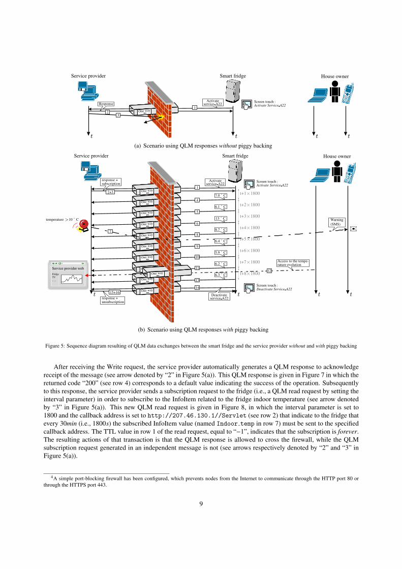
5.1.1. QLM response without piggy backing
Figure 5(a) provides the sequence diagram when the user requests for a specific service related to the smart fridge.
On a more concrete level, the user can activate a service by selecting it via a touch screen available on the fridge,
which automatically generates an appropriate QLM write request that is sent to the service provider (see arrow denoted
by “1” in Figure 5(a)). The QLM write message is given in Figure 6, which includes the “id” of the smart fridge (see
row 6), the name of the service to be activated (it is specified using the InfoItem name as shown in row 7: service
named Service A22), and the value related to this service (see row 8) that corresponds to the user expectation, i.e. to
Activate the service at that time. Service A22 guarantees the three following features: ii) the continual monitoring
of the indoor temperature of the fridge, i) the triggering of an alarm if the indoor temperature exceeds 10˚C (an SMS
is sent to the user’s cell phone), and iii) the possibility for the user to consult at any time the service provider’s web
page to visualize the temperature evolution.
8
t t t t
One way➙
Service provider Smart fridge
xHouse owner
Activateservice A22Response
1
23
Screen touch :Activate Service A22
(a) Scenario using QLM responses without piggy backing
t t t tOne way➙
One way➙
One way➙
t+8×1800One way➙
t+7×1800One way➙
t+6×1800One way➙
t+5×1800One way➙
t+4×1800One way➙
t+3×1800One way➙
t+2×1800One way➙
t+1×1800One way➙
Service provider Smart fridge
xHouse owner
Activateservice A22
7.0˚C
6.1˚C
13˚Ctemperature >10˚C
8.7˚C
6.4˚C
5.9˚C
6.2˚C
6.3˚C
Access to the tempe-rature evolution
Service provider web
Fridge
TV
. . .
Deactivateservice A22
response +subscription
Warning
(SMS)
response +unsubscription
1
2+3
4
5
6
78
9
10
1112
13
14
15+16
Screen touch :Activate Service A22
Screen touch :Deactivate Service A22
✉
(b) Scenario using QLM responses with piggy backing
Figure 5: Sequence diagram resulting of QLM data exchanges between the smart fridge and the service provider without and with piggy backing
After receiving the Write request, the service provider automatically generates a QLM response to acknowledge
receipt of the message (see arrow denoted by “2” in Figure 5(a)). This QLM response is given in Figure 7 in which the
returned code “200” (see row 4) corresponds to a default value indicating the success of the operation. Subsequently
to this response, the service provider sends a subscription request to the fridge (i.e., a QLM read request by setting the
interval parameter) in order to subscribe to the InfoItem related to the fridge indoor temperature (see arrow denoted
by “3” in Figure 5(a)). This new QLM read request is given in Figure 8, in which the interval parameter is set to
1800 and the callback address is set to http://207.46.130.1//Servlet (see row 2) that indicate to the fridge that
every 30min (i.e., 1800s) the subscribed InfoItem value (named Indoor temp in row 7) must be sent to the specified
callback address. The TTL value in row 1 of the read request, equal to “−1”, indicates that the subscription is forever.
The resulting actions of that transaction is that the QLM response is allowed to cross the firewall, while the QLM
subscription request generated in an independent message is not (see arrows respectively denoted by “2” and “3” in
Figure 5(a)).
4A simple port-blocking firewall has been configured, which prevents nodes from the Internet to communicate through the HTTP port 80 or
through the HTTPS port 443.
9

1 <qlmEnvelope xmlns=”QLMmi . xsd ” v e r s i o n=” 1 . 0 ” t t l =” 0 . 0 ”>2 <w r i t e msgformat=”QLMdf . xsd ”>3 <msg>4 <O b j e c t s xmlns=”QLMdf . xsd ”>5 <O b j e c t t y p e=” R e f r i g e r a t o r ”>6 < i d>SmartFridge22334411< / i d>7 < I n f o I t e m name=” S e r v i c e A 2 2 ”>8 <v a l u e>Activate< / v a l u e>9 < / I n f o I t e m>
10 < / O b j e c t>11 < / O b j e c t s>12 < /msg>13 < / w r i t e>14 < / qlmEnvelope>
Figure 6: QLM write message sent by the fridge to the service provider (see arrow denoted by “1” in Figure 5(a))
1 <qlmEnvelope xmlns=”QLMmi . xsd ” v e r s i o n=” 1 . 0 ” t t l =” 0 . 0 ”>2 < r e s p o n s e>3 < r e s u l t>4 < r e t u r n r e t u r n C o d e=” 200 ” />5 < / r e s u l t>6 < / r e s p o n s e>7 < / qlmEnvelope>
Figure 7: Response sent by the service provider to fridge (arrow “2”)
1 <qlmEnvelope xmlns=”QLMmi . xsd ” v e r s i o n=” 1 . 0 ” t t l =”−1”>2 < r e a d msgformat=”QLMdf . xsd ” i n t e r v a l=” 1800 ” c a l l b a c k=” h t t p : / / 2 0 7 . 4 6 . 1 3 0 . 1 / / S e r v l e t ”>3 <msg>4 <O b j e c t s xmlns=”QLMdf . xsd ”>5 <O b j e c t t y p e=” R e f r i g e r a t o r ”>6 < i d>SmartFridge22334411< / i d>7 < I n f o I t e m name=” I n d o o r t e m p ” />8 < / O b j e c t>9 < / O b j e c t s>
10 < /msg>11 < / r e a d>12 < / qlmEnvelope>
Figure 8: Subscription sent by service provider to fridge (arrow “3”)
5.1.2. QLM response with piggy backing
Figure 5(b) provides the sequence diagram when the user requests for Service A22 but, this time, using the
QLM piggy backing property. The QLM write request sent by the fridge to the service provider is similar to the
one given in Figure 6. However, the subscription request given in Figure 8 is now piggy backed with the initial
response given in Figure 7, as illustrated through the arrow denoted by “2+3” in Figure 5(b). The resulting QLM
piggy backed message is given in Figure 9, in which the subscription request (i.e., interface + data format) is included
from row 5 to row 16. Contrary to the previous experiment, the fridge now receives the subscription request and is
able to process it. In our case study, the DIALOG middleware5 is used to integrate the QLM messaging standards
and, among others, the subscription mechanisms. Accordingly, DIALOG creates the appropriate subscription, i.e.
that respects the specified parameters (interval, TTL, callback address if specified, subscribed InfoItem(s). . . ). In this
scenario, DIALOG embedded on the fridge sends the indoor temperature through a new QLM response every 30min,
as illustrated in Figure 5(b) through arrows denoted by “4”, “5”, “6”, “8”, “9”,“10”, “11”, “13”.
Arrows denoted by “7” and “12” are actions related to features ii) and iii) of Service A22 (cf. section 5.1.1).
Arrow “7” illustrates the notification sent by the service provider (via SMS) to inform the user that the fridge temper-
ature exceeded 10˚C. Figure 10 provides the QLM response message sent by the fridge at t + 3 × 1800 that contains
5http://dialog.hut.fi
10
1 <qlmEnvelope xmlns =”QLMmi . xsd ” v e r s i o n =” 1 . 0 ” t t l =” 0 . 0 ”>
2 <r e s p o n s e>
3 < r e s u l t>
4 <r e t u r n r e t u r n C o d e =”200 ” />
5 <qlmEnvelope v e r s i o n =” 1 . 0 ” t t l =”−1”>
6 <r e a d msgformat =”QLMdf . xsd ” i n t e r v a l =” 1800 ” c a l l b a c k =” h t t p : / / 2 0 7 . 4 6 . 1 3 0 . 1 / / QLM Servle t ”>
7 <msg>
8 <O b j e c t s xmlns =”QLMdf . xsd ”>
9 <O b j e c t t y p e =” R e f r i g e r a t o r ”>
10 <i d>SmartFridge22334411</ i d>
11 <I n f o I t e m name=” I n d o o r t e m p ” />
12 </ O b j e c t>
13 </ O b j e c t s>
14 </ msg>
15 </ r e a d>
16 </ q lmEnvelope>
17 </ r e s u l t>
18 </ r e s p o n s e>
19 </ q lmEnvelope>
Subscription request (i.e., read – deferred retrieval)
piggy backed in the response message
QLM-MI response
QLM-DF response
QLM-MI read
QLM-DF read
QLM-MI read
QLM-MI response
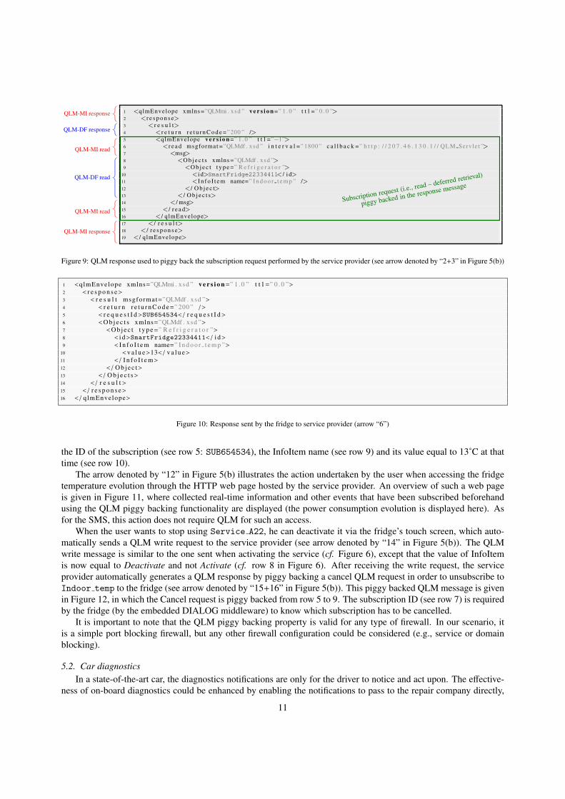
Figure 9: QLM response used to piggy back the subscription request performed by the service provider (see arrow denoted by “2+3” in Figure 5(b))
1 <qlmEnvelope xmlns=”QLMmi . xsd ” v e r s i o n=” 1 . 0 ” t t l =” 0 . 0 ”>2 < r e s p o n s e>3 < r e s u l t msgformat=”QLMdf . xsd ”>4 < r e t u r n r e t u r n C o d e=” 200 ” />5 < r e q u e s t I d>SUB654534< / r e q u e s t I d>6 <O b j e c t s xmlns=”QLMdf . xsd ”>7 <O b j e c t t y p e=” R e f r i g e r a t o r ”>8 < i d>SmartFridge22334411< / i d>9 < I n f o I t e m name=” I n d o o r t e m p ”>
10 <v a l u e>13< / v a l u e>11 < / I n f o I t e m>12 < / O b j e c t>13 < / O b j e c t s>14 < / r e s u l t>15 < / r e s p o n s e>16 < / qlmEnvelope>
Figure 10: Response sent by the fridge to service provider (arrow “6”)
the ID of the subscription (see row 5: SUB654534), the InfoItem name (see row 9) and its value equal to 13˚C at that
time (see row 10).
The arrow denoted by “12” in Figure 5(b) illustrates the action undertaken by the user when accessing the fridge
temperature evolution through the HTTP web page hosted by the service provider. An overview of such a web page
is given in Figure 11, where collected real-time information and other events that have been subscribed beforehand
using the QLM piggy backing functionality are displayed (the power consumption evolution is displayed here). As
for the SMS, this action does not require QLM for such an access.
When the user wants to stop using Service A22, he can deactivate it via the fridge’s touch screen, which auto-
matically sends a QLM write request to the service provider (see arrow denoted by “14” in Figure 5(b)). The QLM
write message is similar to the one sent when activating the service (cf. Figure 6), except that the value of InfoItem
is now equal to Deactivate and not Activate (cf. row 8 in Figure 6). After receiving the write request, the service
provider automatically generates a QLM response by piggy backing a cancel QLM request in order to unsubscribe to
Indoor temp to the fridge (see arrow denoted by “15+16” in Figure 5(b)). This piggy backed QLM message is given
in Figure 12, in which the Cancel request is piggy backed from row 5 to 9. The subscription ID (see row 7) is required
by the fridge (by the embedded DIALOG middleware) to know which subscription has to be cancelled.
It is important to note that the QLM piggy backing property is valid for any type of firewall. In our scenario, it
is a simple port blocking firewall, but any other firewall configuration could be considered (e.g., service or domain
blocking).
5.2. Car diagnostics
In a state-of-the-art car, the diagnostics notifications are only for the driver to notice and act upon. The effective-
ness of on-board diagnostics could be enhanced by enabling the notifications to pass to the repair company directly,
11

Figure 11: User interface hosted by the service provider showing collected real-time information and events
1 <qlmEnvelope xmlns=”QLMmi . xsd ” v e r s i o n=” 1 . 0 ” t t l =” 0 . 0 ”>2 < r e s p o n s e>3 < r e s u l t>4 < r e t u r n r e t u r n C o d e=” 200 ” />5 <qlmEnvelope v e r s i o n=” 1 . 0 ” t t l =” 0 . 0 ”>6 < c a n c e l msgformat=”QLMdf . xsd ”>7 < r e q u e s t I d>SUB654534< / r e q u e s t I d>8 < / c a n c e l>9 < / qlmEnvelope>
10 < / r e s u l t>11 < / r e s p o n s e>12 < / qlmEnvelope>
Figure 12: Piggy backing of the QLM cancel request (arrow “15+16”)
for instance via an ordinary mobile phone with a suitable application. In our platform, we have implemented such an
application on a mobile phone by a Java MIDP program capable of acting as a QLM node, and to send QLM messages
over the mobile network with data downloaded from the car’s Engine Control Unit (ECU). The connection between
the mobile phone and the car’s ECU was implemented using a commercially available OBD-II protocol converter
[50] connected to the mobile phone via Bluetooth, as illustrated in Figure 13. Figure 14 provides a preliminary user
interface on the mobile phone for accessing information from car’s ECU.
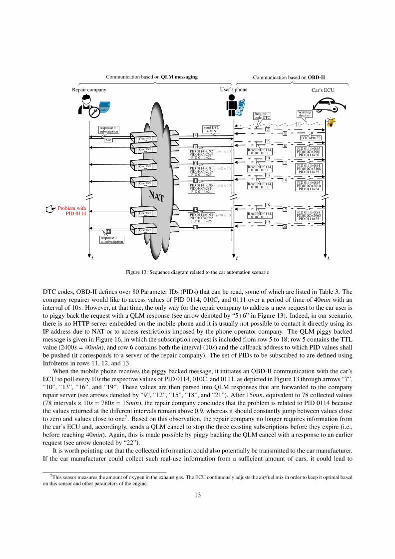
The complete scenario is detailed in Figure 13, in which a warning display notifies the car user of the presence
of deficiencies (see the LED and arrow denoted by “1”). The user therefore solicits the car’s ECU to obtain further
information, and particularly the Diagnostics Trouble Code (DTC) (see arrow denoted by “2”). Table 3 lists some of
the DTC codes defined by OBD-II along with a brief description6. In our scenario, the car’s ECU returns the DTC
code P0172 (see arrow denoted by “3” and Table 3). Accordingly, the user contacts the repair company to further
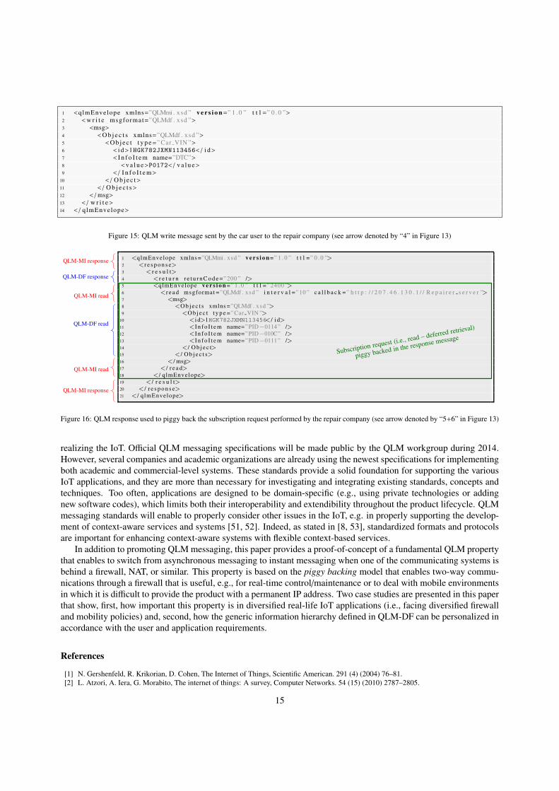
investigate the problem. This is achieved using QLM messaging and not OBD-II protocol. To be more concrete,
the user sends a QLM write request to the repair company by including the DTC code and the Vehicle Identification
Number (VIN); see arrow denoted by “4” in Figure 13. This request is given in Figure 15, in which the Object “id”
corresponds to the VIN (see row 6), the InfoItem name is “DTC”, and its value corresponds to the DTC code P0172
(see rows 7 and 8 respectively).
To aid in further problem determination, scheduling a time for service, ordering needed spare parts, or taking
some other proactive actions, the repair company would like to monitor specific sensors embedded in the car. As for
6There are over 400 DTCs defined in OBD-II.
12
Communication based on QLM messaging Communication based on OBD-II
t t t
NAT
One way➙
One way➙
One way➙
One way➙
One way➙
One way➙
b
Repair company
Problem withPID 0114
Car’s ECU
xUser’s phone
t+1×10
t+2×10
t+3×10
t+79×10
WarningdisplayRequest
code DTC
DTC=P0172
Read PID 0114,010C, 0111
PID 0114=0.92PID010C=2693PID 0111=22
Read PID 0114,010C, 0111
PID 0114=0.91PID010C=2468PID 0111=25
Read PID 0114,010C, 0111
PID 0114=0.95PID010C=2810PID 0111=24
Read PID 0114,010C, 0111
PID 0114=0.93PID010C=2965PID 0111=25
Read PID 0114,010C, 0111
PID 0114=0.95PID010C=2901PID 0111=26
Send DTC+ VIN
response +subscription
PID 0114=0.92PID010C=2693PID 0111=22
PID 0114=0.91PID010C=2468PID 0111=25
PID 0114=0.95PID010C=2810PID 0111=24
PID 0114=0.93PID010C=2965PID 0111=25
response +unsubscription
1
234
5+6
9
12
15
18
2122
7
8
10
11
13
14
16
17
19
20
Figure 13: Sequence diagram related to the car automation scenario
DTC codes, OBD-II defines over 80 Parameter IDs (PIDs) that can be read, some of which are listed in Table 3. The
company repairer would like to access values of PID 0114, 010C, and 0111 over a period of time of 40min with an
interval of 10s. However, at that time, the only way for the repair company to address a new request to the car user is
to piggy back the request with a QLM response (see arrow denoted by “5+6” in Figure 13). Indeed, in our scenario,
there is no HTTP server embedded on the mobile phone and it is usually not possible to contact it directly using its
IP address due to NAT or to access restrictions imposed by the phone operator company. The QLM piggy backed
message is given in Figure 16, in which the subscription request is included from row 5 to 18; row 5 contains the TTL
value (2400s = 40min), and row 6 contains both the interval (10s) and the callback address to which PID values shall
be pushed (it corresponds to a server of the repair company). The set of PIDs to be subscribed to are defined using
InfoItems in rows 11, 12, and 13.
When the mobile phone receives the piggy backed message, it initiates an OBD-II communication with the car’s
ECU to poll every 10s the respective values of PID 0114, 010C, and 0111, as depicted in Figure 13 through arrows “7”,
“10”, “13”, “16”, and “19”. These values are then parsed into QLM responses that are forwarded to the company
repair server (see arrows denoted by “9”, “12”, “15”, “18”, and “21”). After 15min, equivalent to 78 collected values
(78 intervals × 10s = 780s = 15min), the repair company concludes that the problem is related to PID 0114 because
the values returned at the different intervals remain above 0.9, whereas it should constantly jump between values close
to zero and values close to one7. Based on this observation, the repair company no longer requires information from
the car’s ECU and, accordingly, sends a QLM cancel to stop the three existing subscriptions before they expire (i.e.,
before reaching 40min). Again, this is made possible by piggy backing the QLM cancel with a response to an earlier
request (see arrow denoted by “22”).
It is worth pointing out that the collected information could also potentially be transmitted to the car manufacturer.
If the car manufacturer could collect such real-use information from a sufficient amount of cars, it could lead to
7This sensor measures the amount of oxygen in the exhaust gas. The ECU continuously adjusts the air/fuel mix in order to keep it optimal based
on this sensor and other parameters of the engine.
13
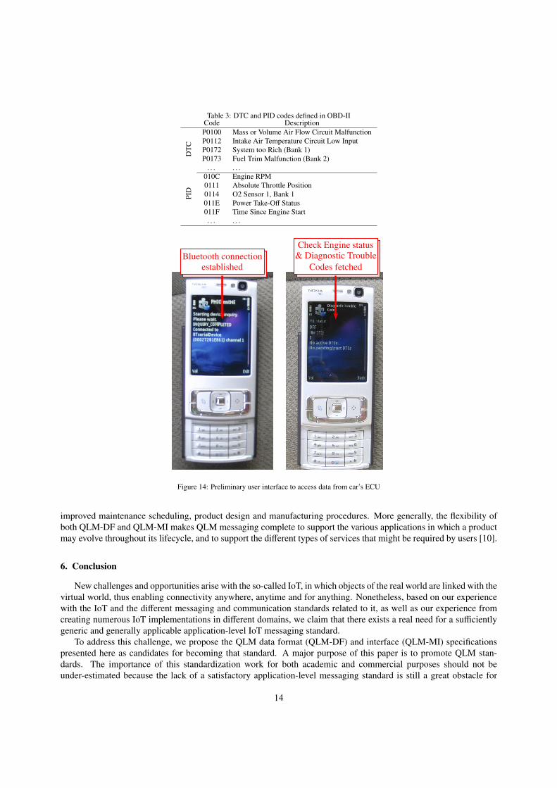
Table 3: DTC and PID codes defined in OBD-IICode Description
DT
C
P0100 Mass or Volume Air Flow Circuit Malfunction
P0112 Intake Air Temperature Circuit Low Input
P0172 System too Rich (Bank 1)
P0173 Fuel Trim Malfunction (Bank 2)
. . . . . .
PID
010C Engine RPM
0111 Absolute Throttle Position
0114 O2 Sensor 1, Bank 1
011E Power Take-Off Status
011F Time Since Engine Start
. . . . . .
Bluetooth connection
established
Check Engine status
& Diagnostic Trouble
Codes fetched
Figure 14: Preliminary user interface to access data from car’s ECU
improved maintenance scheduling, product design and manufacturing procedures. More generally, the flexibility of
both QLM-DF and QLM-MI makes QLM messaging complete to support the various applications in which a product
may evolve throughout its lifecycle, and to support the different types of services that might be required by users [10].
6. Conclusion
New challenges and opportunities arise with the so-called IoT, in which objects of the real world are linked with the
virtual world, thus enabling connectivity anywhere, anytime and for anything. Nonetheless, based on our experience
with the IoT and the different messaging and communication standards related to it, as well as our experience from
creating numerous IoT implementations in different domains, we claim that there exists a real need for a sufficiently
generic and generally applicable application-level IoT messaging standard.
To address this challenge, we propose the QLM data format (QLM-DF) and interface (QLM-MI) specifications
presented here as candidates for becoming that standard. A major purpose of this paper is to promote QLM stan-
dards. The importance of this standardization work for both academic and commercial purposes should not be
under-estimated because the lack of a satisfactory application-level messaging standard is still a great obstacle for
14
1 <qlmEnvelope xmlns=”QLMmi . xsd ” v e r s i o n=” 1 . 0 ” t t l =” 0 . 0 ”>2 <w r i t e msgformat=”QLMdf . xsd ”>3 <msg>4 <O b j e c t s xmlns=”QLMdf . xsd ”>5 <O b j e c t t y p e=” Car VIN ”>6 < i d>1HGK782JXMN113456< / i d>7 < I n f o I t e m name=”DTC”>8 <v a l u e>P0172< / v a l u e>9 < / I n f o I t e m>
10 < / O b j e c t>11 < / O b j e c t s>12 < /msg>13 < / w r i t e>14 < / qlmEnvelope>
Figure 15: QLM write message sent by the car user to the repair company (see arrow denoted by “4” in Figure 13)
1 <qlmEnvelope xmlns =”QLMmi . xsd ” v e r s i o n =” 1 . 0 ” t t l =” 0 . 0 ”>
2 <r e s p o n s e>
3 < r e s u l t>
4 <r e t u r n r e t u r n C o d e =”200 ” />
5 <qlmEnvelope v e r s i o n =” 1 . 0 ” t t l =” 2400 ”>
6 <r e a d msgformat =”QLMdf . xsd ” i n t e r v a l =” 10 ” c a l l b a c k =” h t t p : / / 2 0 7 . 4 6 . 1 3 0 . 1 / / R e p a i r e r s e r v e r ”>
7 <msg>
8 <O b j e c t s xmlns =”QLMdf . xsd ”>
9 <O b j e c t t y p e =” Car VIN ”>
10 <i d>1HGK782JXMN113456</ i d>
11 <I n f o I t e m name=”PID−0114” />
12 <I n f o I t e m name=”PID−010C” />
13 <I n f o I t e m name=”PID−0111” />
14 </ O b j e c t>
15 </ O b j e c t s>
16 </ msg>
17 </ r e a d>
18 </ q lmEnvelope>
19 </ r e s u l t>
20 </ r e s p o n s e>
21 </ q lmEnvelope>
Subscription request (i.e., read – deferred retrieval)
piggy backed in the response message
QLM-MI response
QLM-DF response
QLM-MI read
QLM-DF read
QLM-MI read
QLM-MI response
Figure 16: QLM response used to piggy back the subscription request performed by the repair company (see arrow denoted by “5+6” in Figure 13)
realizing the IoT. Official QLM messaging specifications will be made public by the QLM workgroup during 2014.
However, several companies and academic organizations are already using the newest specifications for implementing
both academic and commercial-level systems. These standards provide a solid foundation for supporting the various
IoT applications, and they are more than necessary for investigating and integrating existing standards, concepts and
techniques. Too often, applications are designed to be domain-specific (e.g., using private technologies or adding
new software codes), which limits both their interoperability and extendibility throughout the product lifecycle. QLM
messaging standards will enable to properly consider other issues in the IoT, e.g. in properly supporting the develop-
ment of context-aware services and systems [51, 52]. Indeed, as stated in [8, 53], standardized formats and protocols
are important for enhancing context-aware systems with flexible context-based services.
In addition to promoting QLM messaging, this paper provides a proof-of-concept of a fundamental QLM property
that enables to switch from asynchronous messaging to instant messaging when one of the communicating systems is
behind a firewall, NAT, or similar. This property is based on the piggy backing model that enables two-way commu-
nications through a firewall that is useful, e.g., for real-time control/maintenance or to deal with mobile environments
in which it is difficult to provide the product with a permanent IP address. Two case studies are presented in this paper
that show, first, how important this property is in diversified real-life IoT applications (i.e., facing diversified firewall
and mobility policies) and, second, how the generic information hierarchy defined in QLM-DF can be personalized in
accordance with the user and application requirements.
References
[1] N. Gershenfeld, R. Krikorian, D. Cohen, The Internet of Things, Scientific American. 291 (4) (2004) 76–81.
[2] L. Atzori, A. Iera, G. Morabito, The internet of things: A survey, Computer Networks. 54 (15) (2010) 2787–2805.
15

[3] F. Wu, Y.-F. Kao, Y.-C. Tseng, From wireless sensor networks towards cyber physical systems, Pervasive and Mobile Computing. 7 (4) (2011)
397–413.
[4] M. Contia, S. K. Dasb, C. Bisdikianc, M. Kumarb, L. M. Nid, A. Passarellaa, G. Roussose, G. Trosterf, G. Tsudikg, F. Zambonellih, Looking
ahead in pervasive computing: Challenges and opportunities in the era of cyber-physical convergence, Pervasive and Mobile Computing. 8
(1) (2012) 2–21.
[5] G. Roussos, V. Kostakos, RFID in pervasive computing: State-of-the-art and outlook, Pervasive and Mobile Computing. 5 (1) (2009) 110–131.
[6] D. J. Cook, S. K. Das, Pervasive computing at scale: Transforming the state of the art, Pervasive and Mobile Computing. 8 (1) (2012) 22–35.
[7] C. Perera, A. Zaslavsky, P. Christen, D. Georgakopoulos, Sensing as a service model for smart cities supported by internet of things, Trans-
actions on Emerging Telecommunications Technologies. 25 (1) (2014) 81–93.
[8] C. Perera, A. Zaslavsky, P. Christen, D. Georgakopoulos, Context aware computing for the internet of things: A survey, IEEE Communications
surveys & Tutorials. 99 (2013) 1–41.
[9] E. Huvio, J. Gronvall, K. Framling, Tracking and tracing parcels using a distributed computing approach, in: Proc. 14th Annual conference
for Nordic researchers in logistics, 2002, 29–43.
[10] D. Kiritsis, Closed-loop PLM for intelligent products in the era of the internet of things, Computer-Aided Design. 43 (5) (2011) 479–501.
[11] K. Framling, J. Holmstrom, J. Loukkol, J. Nyman, A. Kaustell, Sustainable PLM through intelligent products, Engineering Applications of
Artificial Intelligence. 26 (2) (2013) 789–799.
[12] Z. Bi, L. D. Xu, C. Wang, Internet of Things for Enterprise Systems of Modern Manufacturing, IEEE Transactions on Industrial Informatics.
10 (2) (2014) 1537–1546.
[13] H. Cai, L. D. Xu, B. Xu, C. Xie, S. Qin, L. Jiang, IoT-Based Configurable Information Service Platform IoT-Based Configurable Information
Service Platform for Product Lifecycle Management, IEEE Transactions on Industrial Informatics. 10 (2) (2014) 1558–1567.
[14] K. Framling, M. Maharjan, Standardized communication between intelligent products for the IoT, in: Proc. 11th IFAC Workshop on Intelligent
Manufacturing Systems, 2013, 157–162.
[15] S. Paula, R. Jaina, M. Samakab, J. Pan, Application delivery in multi-cloud environments using software defined networking, Computer
Networks, 68 (2014), 166–186.
[16] X. Jin,L. E. Li, L. Vanbever, J. Rexford, Softcell: Scalable and flexible cellular core network architecture, in: Proc. 9th ACM conference on
Emerging networking experiments and technologies, 2013, 163–174.
[17] V. Gupta, M. Wurm, Y. Zhu, M. Millard, S. Fung, N. Gura, H. Eberle, S. Chang, Sizzle: A standards-based end-to-end security architecture
for the embedded internet, Pervasive and Mobile Computing. 1 (4) (2005) 425–445.
[18] I. Lopes, P. Oliveira, Understanding Information Security Culture: A Survey in Small and Medium Sized Enterprises, New Perspectives in
Information Systems and Technologies, Volume 1, 2014, 277–286.
[19] A. Norta, P. Grefen, N. C. Narendra, Sizzle: A standards-based end-to-end security architecture for the embedded internet, Data & Knowledge
Engineering. 91 (2014) 52–89.
[20] L. Chen, Application perspectives for active safety system based on internet of vehicles, in: Proc. FISITA 2012 World Automotive Congress,
2012, 147–152.
[21] M. La Polla, F. Martinelli, D. Sgandurra, A Survey on Security for Mobile Devices, IEEE Communications Surveys & Tutorials . 15 (1)
(2013) 446–471.
[22] R. Barthel, A. Kroner, J. Haupert, Mobile interactions with digital object memories, Pervasive and Mobile Computing. 9 (2) (2013) 281–294.
[23] L. Veasman, Piggy backing on the web 2.0 internet: Copyright liability and web 2.0 mashups, Hastings Comm. & Ent. LJ. 30 (2007) 311–333.
[24] J. Stark, Product lifecycle management: 21st century paradigm for product realisation, Springer, 2011.
[25] K.-D. Thoben, J. Eschenbacher, H. Jagdev, Extended products: evolving traditional product concepts, in: Proc. 7th international Conference
on Concurrent Enterprising Engineering the Knowledge Economy Through Co-operation, 2001, 429–439.
[26] G. G. Meyer, K. Framling, J. Holmstrom, Intelligent products: A survey, Computers in Industry. 60 (3) (2009) 137–148.
[27] D. McFarlane, S. Sarma, J. L. Chirn, C. Y. Wong, The intelligent product in manufacturing control and management, Journal of EAIA. 37 (1)
(2013) 69–88.
[28] S. Kubler, M. Madhikermi, K. Framling, QLM messaging standards: introduction and comparison with existing messaging protocols, Service
Orientation in Holonic and Multi-Agent Manufacturing and Robotic, 544, 237–256.
[29] K. Framling, M. Harrison, J. Brusey, J. Petrow, Requirements on unique identifiers for managing product lifecycle information: comparison
of alternative approaches, International Journal of Computer Integrated Manufacturing. 20 (7) (2007) 715–726.
[30] K. Framling, T. Ala-Risku, M. Karkkainen, J. Holmstrom, Design patterns for managing product life cycle information, Communications of
the ACM. 50 (6) (2007) 75–79.
[31] E. Gamma, R. Helm, R. Johnson, J. Vlissides, Design patterns: elements of reusable object-oriented software, Reading: Addison Wesley
Publishing Company. (1995).
[32] P. T. Eugster, P. A. Felber, R. Guerraoui, A.-M. Kermarrec, The many faces of publish/subscribe, ACM Computing Surveys. 35 (2) (2003)
114–131.
[33] Z. Yan, P. Zhang, A. V. Vasilakos, A survey on trust management for Internet of Things, Journal of Network and Computer Applications. 42
(2014) 120–134.
[34] R. Roman, P. Najera, J. Lopez, Securing the internet of things, Computer. 44 (9) (2011) 51–58.
[35] Zhong, J., Enforcing privacy via access control and data perturbation, PhD thesis, RMIT University, 2013.
[36] R. B. Jennings, E. M. Nahum, D. P. Olshefski, D. Saha, Z.-Y. Shae, C. Waters, A study of internet instant messaging and chat protocols, IEEE
Network. 20 (4) (2006) 16–21.
[37] A. Celesti, M. Villari, A. Puliafito, A Diversified Set of Security Features for XMPP Communication Systems Useful in Cloud Computing
Federation, International Journal on Advances in Security. 6 (3-4) (2013) 99–110.
[38] S. Bendel, T. Springer, D. Schuster, R. Ackermann, M. Ameling, A service infrastructure for the Internet of Things based on XMPP, in: Proc.
IEEE International Conference on Pervasive Computing and Communications Workshops, 2013, 385–388.
[39] E. Aitenbichler, J. Kangasharju, M. Muhlhauser, MundoCore: A light-weight infrastructure for pervasive computing, Pervasive and Mobile
16
Computing. 3 (4) (2007) 332–361.
[40] L. Richardson, S. Ruby, RESTful web services, O’Reilly, 2008.
[41] A. Meniya, H. B. Jethva, Next Generation Mobile Application in Cloud Computing: using RESTful Web Service, LAP Lambert Academic
Publishing, 2012.
[42] E. Bozdag, A. Mesbah, A. Van Deursen, A comparison of push and pull techniques for AJAX, in: Proc. 9th IEEE International Workshop on
Web Site Evolution, 2007, 15–22.
[43] V. Wang, F. Salim, P. Moskovits, The Definitive Guide to HTML5 WebSocket, Apress, 2013.
[44] D. Mitrovic, M. Ivanovic, Z. Budimac, M. Vidakovic, Radigost: Interoperable web-based multi-agent platform, Journal of Systems and
Software. 90 (2014) 167–178.
[45] V. Pimentel, B. G. Nickerson, Communicating and displaying real-time data with WebSocket, IEEE Internet Computing. 16 (4) (2012) 45–53.
[46] N. Dhanjani, B. Rios, B. Hardin, Hacking: The Next Generation, O’Reilly Media, 2009.
[47] Z. Antonioua, S. Zyto, D. N. Kalofonos, P2P social networking for the rest of US, Pervasive and Mobile Computing. 6 (5) (2010) 512–526.
[48] C. Bisdikiana, C. Gibsonb, S. Chakrabortyc, M. B. Srivastava, M. Sensoy, T. J. Norman, Inference management, trust and obfuscation
principles for quality of information in emerging pervasive environments, Pervasive and Mobile Computing. 11 (2014) 168–187.
[49] M. Taneja, An analytics framework to detect compromised IoT devices using mobility behavior, in: Proc. International Conference on ICT
Convergence, 2013, 38–43.
[50] International Organization for Standardization, ISO 15765: Road vehicles, Diagnostics on Controller Area Networks (CAN), 2004.
[51] G. Pallapa, S. K. Das, M. Di Francesco, T. Aura, Adaptive and context-aware privacy preservation exploiting user interactions in smart
environments, Pervasive and Mobile Computing. 12 (2014) 232–243.
[52] E. C.-H. Ngai, P. Gunningberg, Quality-of-information-aware data collection for mobile sensor networks, Pervasive and Mobile Computing.
11 (2014) 203–215.
[53] P. Bellavista, A. Corradi, M. Fanelli, L. Foschini, A Survey of Context Data Distribution for Mobile Ubiquitous Systems, ACM Computing
Surveys. 45 (1) (2013) 1–49.
17
Related Documents