A Snake for Retinal Vessel Segmentation L. Espona 1 , M.J. Carreira 1 , M. Ortega 2 , and M.G. Penedo 2 1 Computer Vision Group. Dpto. Electr´ onica e Computaci´ on. Universidade de Santiago de Compostela. Spain [email protected], [email protected] 2 Grupo VARPA. Dpto. de Computaci´ on. Universidade da Coru˜ na. Spain [email protected] Abstract. This paper presents an innovative methodology to detect the vessel tree in retinal angiographies. The automatic analysis of retinal vessel tree facili- tates the computation of the arteriovenous index, which is essential for the diag- nosis of a wide range of eye diseases. We have developed a system inspired in the classical snake but incorporating domain specific knowledge, such as blood vessels topological properties. It profites mainly from the automatic localization of the optic disc and from the extraction and enhancement of the vascular tree centerlines. Encouraging results in the detection of arteriovenous structures are efficiently achieved, as shown by the systems performance evaluation on the pub- licy available DRIVE database. 1 Introduction The automatic analysis of blood vessels is becoming more and more important in many clinical investigations and scientific researches related to vascular features. The early di- agnosis of several pathologies, such as arterial hypertension, arteriosclerosis or diabetic retinophaty could be achieved analysing the vascular structures. The Digital Colour Fundus Photographs here used are a non invasive and innocuous technique to obtain the retinal vascular tree. Moreover, a specific CAD system is also necessary in large-scale ocular screening programs to make the ophthalmologist diagnosis process more effi- cient and accurate [1]. The retina arteriovenous index (AV index) indicates the relation between afferent and efferent blood vessels, that is arteries and veins of the retina. This index takes a vital priority in order to diagnose these illnesses and evaluate their conse- quences. This paper deals with the research of a vascular tree detection system, which would constitute the first step to allow the precise and robust AV index measuring [2]. The retinal angiographies are 2-D medical images quite problematic. The main dif- ficulties in them are the inadequate contrast, lighting variations and remarkable noise influence mainly due to its complex acquisition. Another drawback is the anatomic vari- ability depending on the particular patient, affecting both the retinal background texture and the blood vessels structure. Blood vessels particular features make them complex structures to detect as the color of vascular structures is not constant even along the same vessel. Their tree-like geometry is often strange and complicated, including bifurcations and overlaps that may mix up the detection system. Nevertheless, other characteristics, like the linearity or the tubular shape, could make the contour detection easier. J. Mart´ ı et al. (Eds.): IbPRIA 2007, Part II, LNCS 4478, pp. 178–185, 2007. c Springer-Verlag Berlin Heidelberg 2007

Welcome message from author
This document is posted to help you gain knowledge. Please leave a comment to let me know what you think about it! Share it to your friends and learn new things together.
Transcript
A Snake for Retinal Vessel Segmentation
L. Espona1, M.J. Carreira1, M. Ortega2, and M.G. Penedo2
1 Computer Vision Group. Dpto. Electronica e Computacion. Universidade deSantiago de Compostela. Spain
[email protected], [email protected] Grupo VARPA. Dpto. de Computacion. Universidade da Coruna. Spain
Abstract. This paper presents an innovative methodology to detect the vesseltree in retinal angiographies. The automatic analysis of retinal vessel tree facili-tates the computation of the arteriovenous index, which is essential for the diag-nosis of a wide range of eye diseases. We have developed a system inspired inthe classical snake but incorporating domain specific knowledge, such as bloodvessels topological properties. It profites mainly from the automatic localizationof the optic disc and from the extraction and enhancement of the vascular treecenterlines. Encouraging results in the detection of arteriovenous structures areefficiently achieved, as shown by the systems performance evaluation on the pub-licy available DRIVE database.
1 Introduction
The automatic analysis of blood vessels is becoming more and more important in manyclinical investigations and scientific researches related to vascular features. The early di-agnosis of several pathologies, such as arterial hypertension, arteriosclerosis or diabeticretinophaty could be achieved analysing the vascular structures. The Digital ColourFundus Photographs here used are a non invasive and innocuous technique to obtain theretinal vascular tree. Moreover, a specific CAD system is also necessary in large-scaleocular screening programs to make the ophthalmologist diagnosis process more effi-cient and accurate [1]. The retina arteriovenous index (AV index) indicates the relationbetween afferent and efferent blood vessels, that is arteries and veins of the retina. Thisindex takes a vital priority in order to diagnose these illnesses and evaluate their conse-quences. This paper deals with the research of a vascular tree detection system, whichwould constitute the first step to allow the precise and robust AV index measuring [2].
The retinal angiographies are 2-D medical images quite problematic. The main dif-ficulties in them are the inadequate contrast, lighting variations and remarkable noiseinfluence mainly due to its complex acquisition. Another drawback is the anatomic vari-ability depending on the particular patient, affecting both the retinal background textureand the blood vessels structure. Blood vessels particular features make them complexstructures to detect as the color of vascular structures is not constant even along the samevessel. Their tree-like geometry is often strange and complicated, including bifurcationsand overlaps that may mix up the detection system. Nevertheless, other characteristics,like the linearity or the tubular shape, could make the contour detection easier.
J. Martı et al. (Eds.): IbPRIA 2007, Part II, LNCS 4478, pp. 178–185, 2007.c© Springer-Verlag Berlin Heidelberg 2007
A Snake for Retinal Vessel Segmentation 179
As blood vessels segmentation becomes essential for several medical diagnostic sys-tems, numerous research efforts have been done in this field. The vascular detection hasbeen tackled from different approaches and techniques including pattern recognition,pixel-based approaches [3] or classification methods [4]. The contour deformable mod-els are widely followed in vessel tracking, even combined with other techniques [6].Even though many promising techniques and algorithms have been developed, vesselsegmentation is still an open area for more research. For further reading on retinal fun-dus image segmentation, we refer to comparative studies as [5].
This work presents an innovative methodology, which incorporates domain specificknowledge into the generic contour deformable model. The snake model is specialisedwith the blood vessels topological properties, which determine the detection systembehaviour. We have taken a great advantage of the vascular tree graph, composed bythe vessels centerlines obtained from a creases extraction system developed previouslyby a research group [7]. The system initialisation includes grayscale conversion of theoriginal image and re-sampling with bi-cubic interpolation to work at subpixel level ina three dimensional space. This is very important for the arteriovenous index calculus,where accurate and fast measures of vessel diameters are needed, as it will be shown inthe results section.
Next we will explain our vessel tree detection system, beginning with crease extrac-tion in order to perform the deformable contour evolution.
2 Vessel Tree Detection System
Our model for the detection of the vessel tree is based on a deformable contour guidedby a vessel crease. This section will begin explaining the creases extraction process,thenthe classical deformable contour model will be described. Once the theorical funda-mentals have been presented, our particular snake model will be analysed in depth,presenting the innovative specific features and their resulting behaviour.
2.1 Creases Extraction
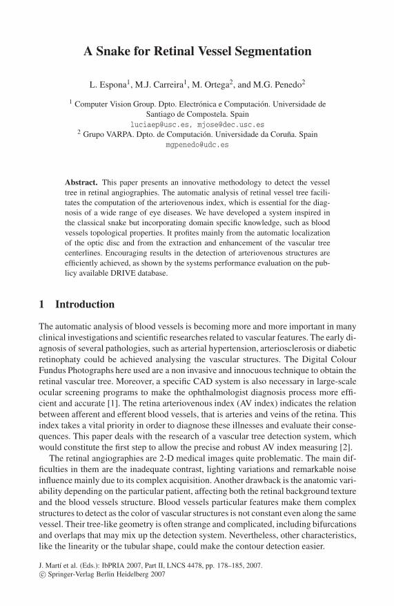
A crease is a continuous area of points on the image, shaping a highest or a lowestlevel in its environment. In this way, blood vessels can be considered as regions whichform an extreme and tubular level on their neighbourhood. This fact allows to locate thevessels by using the creases position (see Fig. 1(a)). The creases extraction is essentialfor the detection process, since it will determine the initial snake and act as externalenergy guiding the contour expansion.
The creases image is obtained using the MLSEC-ST operator(Multilevel Set Extrin-sic Curvature based on the Structure Tensor) as explained in [7]. The parameters wichcontrol the crease expansion are: confidence degree (Confidence), minimum grey level(MinGrey), deviation of a Gaussian smoothing, and the minimum length (MinLenght).These parameters must be fine-tuned to obtain high-quality results.
The creases extraction is a crucial and irreversible step in the snake evolution. If acrease is not detected, the corresponding vessel will remain unsegmented. Thus, wehave enhanced the creases image by exploiting an existent tool, part of a biometric au-thentication system from our research group [8]. The feature points (ridge endings and
180 L. Espona et al.
(a) (b)
Fig. 1. Creases image: (a) A retinal image with its creases overlapped in white, corresponding tothe vessel centerlines. (b) Creases image enhanced in terms of continuity.
bifurcations) obtained with this system are adequately connected to get rid of disconi-nuites along the centerline that guides the snake advance properly(see Fig. 1(b)).
Once the creases were introduced, we will see how they will be used in our snakemodel.
2.2 Deformable Contour Model
Our approach is based on the deformable contour model, also called snake model, pro-posed by Kass et al. [9] to segment objects in 2-D images. A snake is a parametric curvewhich can evolve to fit the shape of the desired structure and it may be represented byv(s) = (x(s),y(s)), where s is the arc length. Once placed on the image, this curve per-forms an iterative contour adaptation in order to minimise its global energy defined asthe sum of the internal and the external energy. The internal energy controls to the snakeflexibility and elasticity and the external energy corresponds to the forces that drive thesnake towards the edges of the shape to locate. The contour deforms under the influ-ence of internal and external forces until it reaches the minimum of its global energyfunction.
This deformable contour can be seen as a polynomial closed contour composed bylinked nodes. This particular snake model will not consider the internal energy as thevessel shape may be very tortuous. Based on the external energy, three possible nodestates are defined : normal, crease and edge. The nodes in the crease state are located inthe vessel crease and they make the snake to advance along the vessel center line. Thepositions close to vessel boundaries are occupied by nodes in the edge state that tendto become stable when reaching the vessel edge. The rest of nodes are in the normalstate and they contribute to the snake expansion in an intermediate direction. Thus, theexternal energy affecting the snake will be defined as a set of energies and weightingfactors:
εext = γεedge + δεcres + νεdir + σεmark + ωεdi f (1)
The first term εedge corresponds to the edge distance energy calculated by assigning toeach point its euclidean distance to the nearest edge obtained with the Canny Filter [10].
A Snake for Retinal Vessel Segmentation 181
This energy helps the snake advance of nodes close to vessel boundaries but it alsostops them when they reach an edge point . The second term εcres corresponds to thecreases distance energy obtained from the crease image just in the same way as forthe edges. This energy drives the snake along the arteriovenous structure and blocks itif a maximum distance threshold is reached. The inflate pressure εdir is the strongestexpansion force of the snake. Each node has one assigned direction that determines thethree adjacent possible positions to choose the one with the lowest energy. The fourthterm εmark is the marker energy to ensure that self overlapping or turning back neverhappens. The difference energy εdi f reinforces the precision of the snake expansion asit hints the nodes to occupy positions different from its neighbours situations.
2.3 Contour Evolution
Once introduced the energy functions influencing the snake, we have to deal with thesnake initialisation.
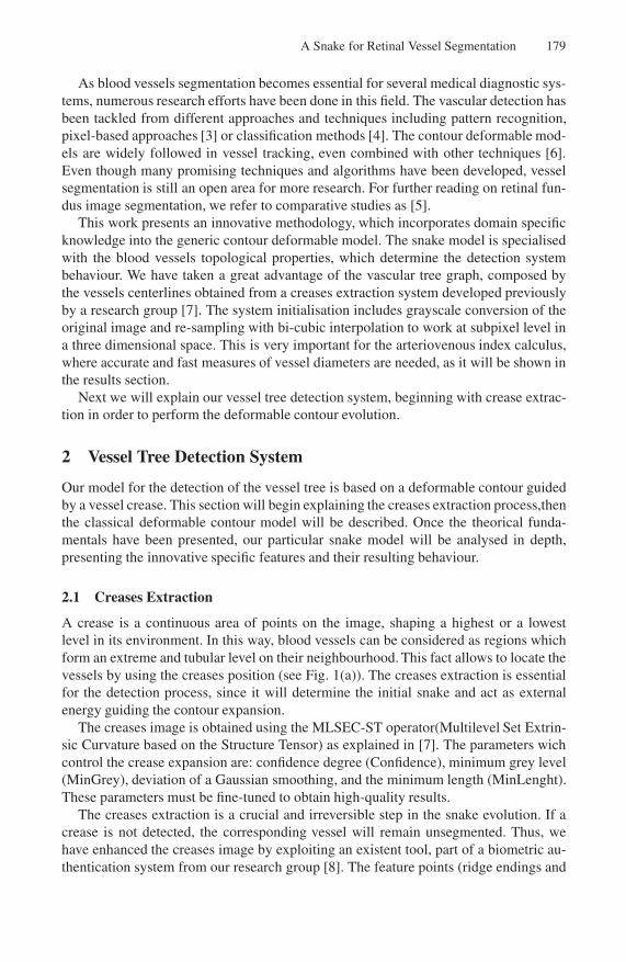
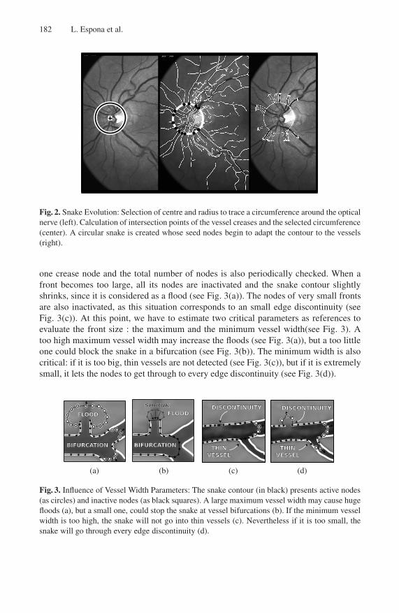
Firstly, the creases and edge images and energy maps are calculated on the origi-nal re-sampled image. Next, a circumference surrounding optical nerve is traced eitherautomatically by an integrated tool developed by a research team [11] or manually,and then the intersections of creases and this circumference are directly obtained (seeFig. 2). A unique snake is created, which corresponds exactly with the previously tracedcircumference and it is composed by inactive nodes, except those placed close enoughto the intersection with creases, called seed nodes.
After its initialisation, the snake evolves following a deterministic and iterative al-gorithm to minimise these energy functions locally (see Fig. 2). Each active node triesto move towards a lower energy position until it becomes irreversibly inactive whenarriving to an edge or due to the control operations that will be described below. Thesystem execution automatically ends when all nodes are inactive, that is, when the snakereaches the stability. To completely segment the vascular structure, the snake grows bynew active nodes insertion considering an euclidean distance threshold.
At a given moment, the snake nodes have a position in the image space and an as-signed node state: edge, normal or crease. The nodes in the edge state are near vesselboundaries, so they are supposed to be soon stabilised when arriving to an edge point.Naturally, the most significant energy term for edge nodes is the edge distance εedge.These weights are similar for normal state nodes, as they are expected to become edgenodes, except in situations such as bifurcations. The crease state is assigned to cen-tral nodes, that are in charge of the snake advance along the vessel centerline. There-fore, they are strongly influenced by the inflate pressure and the crease distance energyterms. These behaviour is modeled by sets of energy term weights associated to eachnode state. The energy for each possible node movement is calculated considering theenergy terms values associated to the position and the weights associated to the node.Iteratively, each vertex is moved according to forces that work on it, that is towardsthe local minimum energy situation. Consequently, the whole contour expands and thesnake flows inside the vessel covering the vascular branch.
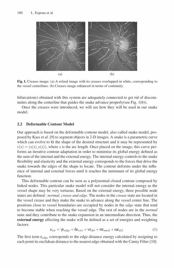
In addition, we perform control operations derived from vessel structural features(seeFig. 3). These control operations work considering the snake as composed by sequencesof consecutive active nodes, called forward fronts. Each front is forced to have exactly
182 L. Espona et al.
Fig. 2. Snake Evolution: Selection of centre and radius to trace a circumference around the opticalnerve (left). Calculation of intersection points of the vessel creases and the selected circumference(center). A circular snake is created whose seed nodes begin to adapt the contour to the vessels(right).
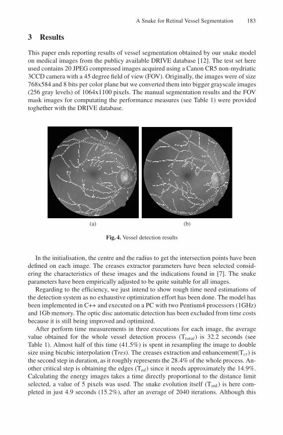
one crease node and the total number of nodes is also periodically checked. When afront becomes too large, all its nodes are inactivated and the snake contour slightlyshrinks, since it is considered as a flood (see Fig. 3(a)). The nodes of very small frontsare also inactivated, as this situation corresponds to an small edge discontinuity (seeFig. 3(c)). At this point, we have to estimate two critical parameters as references toevaluate the front size : the maximum and the minimum vessel width(see Fig. 3). Atoo high maximum vessel width may increase the floods (see Fig. 3(a)), but a too littleone could block the snake in a bifurcation (see Fig. 3(b)). The minimum width is alsocritical: if it is too big, thin vessels are not detected (see Fig. 3(c)), but if it is extremelysmall, it lets the nodes to get through to every edge discontinuity (see Fig. 3(d)).
(a) (b) (c) (d)
Fig. 3. Influence of Vessel Width Parameters: The snake contour (in black) presents active nodes(as circles) and inactive nodes (as black squares). A large maximum vessel width may cause hugefloods (a), but a small one, could stop the snake at vessel bifurcations (b). If the minimum vesselwidth is too high, the snake will not go into thin vessels (c). Nevertheless if it is too small, thesnake will go through every edge discontinuity (d).
A Snake for Retinal Vessel Segmentation 183
3 Results
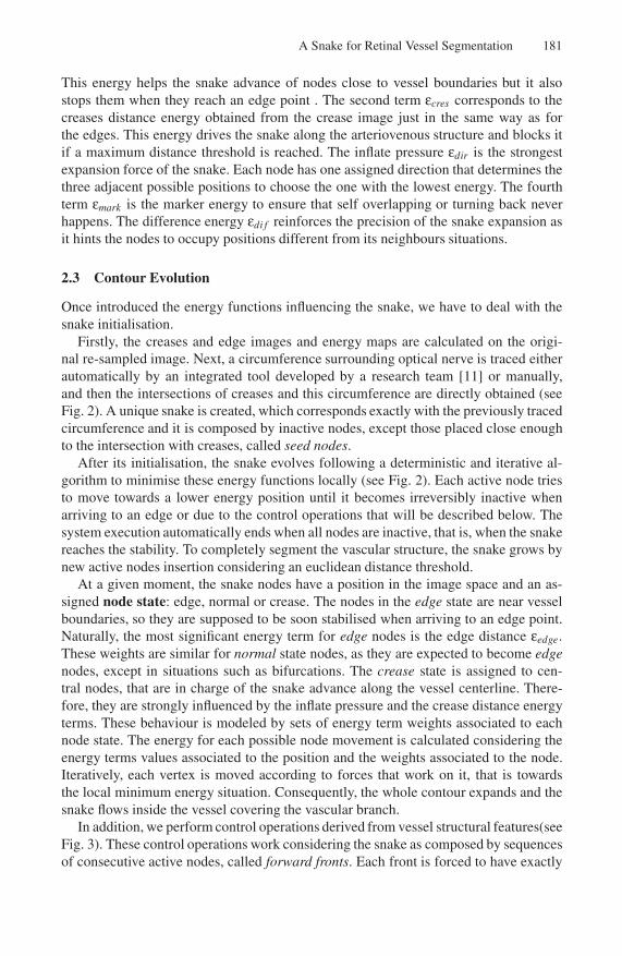
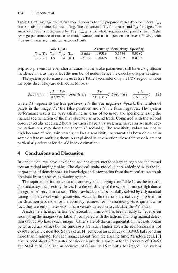
This paper ends reporting results of vessel segmentation obtained by our snake modelon medical images from the publicy available DRIVE database [12]. The test set hereused contains 20 JPEG compressed images acquired using a Canon CR5 non-mydriatic3CCD camera with a 45 degree field of view (FOV). Originally, the images were of size768x584 and 8 bits per color plane but we converted them into bigger grayscale images(256 gray levels) of 1064x1100 pixels. The manual segmentation results and the FOVmask images for computating the performance measures (see Table 1) were providedtoghether with the DRIVE database.
(a) (b)
Fig. 4. Vessel detection results
In the initialisation, the centre and the radius to get the intersection points have beendefined on each image. The creases extractor parameters have been selected consid-ering the characteristics of these images and the indications found in [7]. The snakeparameters have been empirically adjusted to be quite suitable for all images.
Regarding to the efficiency, we just intend to show rough time need estimations ofthe detection system as no exhaustive optimization effort has been done. The model hasbeen implemented in C++ and executed on a PC with two Pentium4 processors (1GHz)and 1Gb memory. The optic disc automatic detection has been excluded from time costsbecause it is still being improved and optimized.
After perform time measurements in three executions for each image, the averagevalue obtained for the whole vessel detection process (Ttotal) is 32.2 seconds (seeTable 1). Almost half of this time (41.5%) is spent in resampling the image to doublesize using bicubic interpolation (Tres). The creases extraction and enhancement(Tcr) isthe second step in duration, as it roughly represents the 28.4% of the whole process. An-other critical step is obtaining the edges (Ted) since it needs approximately the 14.9%.Calculating the energy images takes a time directly proportional to the distance limitselected, a value of 5 pixels was used. The snake evolution itself (Tsnk) is here com-pleted in just 4.9 seconds (15.2%), after an average of 2040 iterations. Although this
184 L. Espona et al.
Table 1. Left: Average execution times in seconds for the proposed vessel detecion model. Tres
corresponds to double size resampling. The extraction is Tcr for creases and Ted for edges. Thesnake evolution is represented by Tsnk. Ttotal is the whole segmentation process time. Right:Average performance of our snake model (Snake) and an independent observer (2ndOb.), withthe same human segmentation as ground truth.
Time CostsTres Tcr Ted Tsnk Ttot
13.3 9.1 4.8 4.9 32.1
Accuracy Sensitivity SpecifitySnake 0.9316 0.6634 0.96822ndOb. 0.9486 0.7732 0.9726
step now presents an even shorter duration, the snake parameters still have a significantincidence on it as they affect the number of nodes, hence the calculations per iteration.
The system performance mesures (see Table 1) consider only the FOV region withoutthe optic disc. They are defined as follows:
Accuracy =T P+ TN#pixels
; Sensitivity =TP
T P+ FN; Speci f ity =
T NT N + FP
; (2)
where T P represents the true positives, T N the true negatives, #pixels the number ofpixels in the image, FP the false positives and FN the false negatives. The systemperformance results are very satisfying in terms of accuracy and specificity, using themanual segmentation of the first observer as ground truth. Compared with the secondobserver results needing 2 hours for each image, this system achieves an accurate seg-mentation in a very short time (about 32 seconds). The sensitivity values are not sohigh because of very thin vessels, in fact a sensitivity increment has been obtained insome draft tests omitting them. As explained in next section, these thin vessels are notparticularly relevant for the AV index estimation.
4 Conclusions and Discussion
In conclusion, we have developed an innovative methodology to segment the vesseltree on retinal angiographies. The classical snake model is here redefined with the in-corporation of domain specific knowledge and information from the vascular tree graphobtained from a creases extraction system.
The reported performance results are very encouraging (see Table 1), as the remark-able accuracy and specifity shows. Just the sensitivity of the system is not so high due tounsegmented very thin vessels. This drawback could be partially solved by a dynamicaltuning of the vessel width parameter. Actually, thin vessels are not very important inthe detection process since the accuracy required for ophthalmologists is quite low. Infact, they are only interested on main vessels detection to calculate the AV index.
A extreme efficiency in terms of execution time cost has been already achieved evenresampling the images (see Table 1), compared with the tedious and long manual detec-tion (about two hours each image). Other state-of-the-art segmentation methods obtainbetter accuracy values but the time costs are much higher. Even the performance is notexactly equally calculated Soares et al. [4] achieved an accuracy of 0.9466 but spendingmore than 3 minutes for each image, appart from the training time. Mendoca et al. [3]results need about 2.5 minutes considering just the algorithm for an accuracy of 0.9463and Staal et al. [12] get an accuracy of 0.9441 in 15 minutes for image. Our system
A Snake for Retinal Vessel Segmentation 185
reaches an average accuracy of 0.9316 in just 30 seconds, because it does not need toperform any complicated image preprocessing and it only handles one snake instancefor the whole vascular tree. This short execution time for image, makes it suitable forreal-time applications.
Our researching efforts are now mainly focused on automatically tuning the parame-ters depending on the image and on enhancing and optimising the energy minimisation.This system can be used in other applications related to retinal or vascular pathologies.To set an example, removing the vessel tree detected could make easier the location ofretinal background lessions.
Acknowledgements. This paper has been partly funded by the Xunta de Galicia andthe Ministerio de Ciencia y Tecnologıa through grant contracts TIC2003-04649-C02and PGIDIT04PXIC20602PN. We also would like to thank the authors of the DRIVEdatabase for making their data publicy available [12].
References
1. Niemeijer, M., van Ginneken, B., Staal, J., Suttorp-Schulten, M.S.A., Abramoff, M.D.: Au-tomatic Detection of Red Lesions in Digital Color Fundus Photographs. IEEE Transactionson Medical Imaging 24(5), 584–592 (2005)
2. Aurell, E., col.: A Note of Signs in the Fundus Oculi Hypertension Conventional Assessmentand Significance. Bull. World Health Organ. 34, 95–960 (1967)
3. Mendoca, A.M., Campilho, A.: Segmentation of Retinal Blood Vessels by Combining theDetection of Centerlines and Morphological Reconstruction. IEEE Transactions on MedicalImaging 25(9), 1200–1213 (2006)
4. Soares, J.V.B., Leandro, J.J.G., Cesar Jr., R.M.C., Jelinek, Cree, M.J.: Retinal Vessel Seg-mentation Using the 2-D Gabor Wavelet and Supervised Classification. IEEE Transactionson Medical Imaging 25(9), 1214–1222 (2006)
5. Niemeijer, M., Staal, J., van Ginneken, B., Loog, M., Abramoff, M.D.: Comparative Study ofRetinal Vessel Segmentation Methods on a new Publicy Avaliable Database. In: Proceedingsof the SPIE. Medical Imaging 2004: Image Processing, vol. 5370, pp. 648–656 (2004)
6. Toledo, R., Orriols, X., Binefa, X., Redeva, P., Vitri, J., Villanueva, J.J.: Tracking elongatedstructures using statistical snakes. In: Proceedings IEEE Conference on Computer Vision andPattern Recognition, vol. 1(1), pp. 157–162 (2000)
7. Caderno, I.G., Penedo, M.G., Marino, C., Carreira, M.J., Gomez-Ulla, F., Gonzalez, F.: Au-tomatic Extraction of the Retina AV Index. LNCS 3212, vol. 2, pp. 132–140, (2004)
8. Ortega, M., Marino, C., Penedo, M.G., Blanco, M., Gonzalez, F.: Personal Authenticationbased on Feature Extraction and Optic Nerve Location in Digital Retinal Images WseasTransactions on Computers, vol. 5(6), pp. 1169–1176 (2006)
9. Kass, M., Witkin, A., Terzopoulos, D.: Active Contour Models. International Journal ofComputer Vision 1(2), 321–331 (1998)
10. Canny, J.A: Computational Approach to Edge-Detection. IEEE Transactions on PatternAnalysis and Machine Inteligence 8(6), 679–689 (1986)
11. Blanco, M., Penedo, M.G., Barreira, N., Penas, M., Carreira, M.J.: Localization and Ex-traction of the Optic Disc using th Fuzzy Circular Hough Transform Artificial Intelligenceand Soft Computing. In: Rutkowski, L., Tadeusiewicz, R., Zadeh, L.A., Zurada, J.M. (eds.)ICAISC 2006. LNCS (LNAI), vol. 4029, pp. 713–721. Springer, Heidelberg (2006)
12. Staal, J.J., Abramoff, M.D., Niemeijer, M., Viergever, M.A., van Ginneken, B.: Ridge basedvessel segmentation in color images of the retina. IEEE Transactions on Medical Imaging 23,501–509 (2004)
Related Documents


![Automated Layer Segmentation of 3D Macular Images Using ...csstyyl/papers/icig2015a.pdf · retinal layer segmentation methods. Snake based methods [11] attempt to minimize the energy](https://static.cupdf.com/doc/110x72/600aa3533d64c7524749ead9/automated-layer-segmentation-of-3d-macular-images-using-csstyylpapersicig2015apdf.jpg)