A Smart Surf David R. W Scho The University of Manchester e-mail: [email protected].u Abstract – A versatile simulation system observing the effects of different algorithmi approaches to physical object manipulation via - physical machines which use a distributed algorithmically controlled to manipulate obj them. The system presented is a graphical 3D simulator that allows the modeller to includ hardware related constraints such as inter-ob trajectories, mechanical properties, friction, a reliability, while conducting experiments i repeatable and controlled environment. Index Terms – Smart Surface, Actuator A Manipulator, Bio-inspired robotics, Cyber- Cellular Automata, Simulation, Physical Model I. INTRODUCTION mart surfaces, or distributed manip physical devices that can 'intellig objects placed upon them. Whilst t definition of a smart surface, they can be having: 1) Sensors - A variety of sensors determine features about the objects placed These can be global sensors (e.g. overh distributed sensors (e.g. arrays of photo- sensors). 2) Control - The features are classif system, typically to identify the object, or to properties of the object to determine orientation. The control system determines based upon the state of the surface. 3) Manipulation – Coordinated physica the objects occurs via spatially distributed ac of actuators using linear motors, vibration, m air-currents, etc.). Smart surfaces are controlled eithe all actuators and sensors work under th centralised supervisor, or in a distributed m sensors and actuators are locally self-con information with their neighbours. T applications of smart surfaces might includ components, or guided motion of objects via dynamically in response to other objects traje the surface. S face Simulation Environ W. Barr, Declan Walsh and Piotr Dudek ool of Electrical & Electronic Engineering r, Sackville Street Building, Manchester, M13 9PL, U uk; [email protected]; p.dud m is presented, for ic and mechanical a “smart” surfaces array of actuators jects placed upon D physics sandbox de real-world and bject collisions and nd sensor/actuator in an interactive, Array, Distributed Physical Systems, l pulator arrays, are gently' manipulate there is no formal characterised by may be used to upon the surface. head camera) or -detectors/pressure fied by a control o measure various its position and a resultant action al manipulation of ctuation (e.g. array magnetic levitation, er globally, where e guidance of a manner, where all ntrolling, sharing Typical practical de the sorting of a path determined ectories sensed by Examples of physical actua various actuation mechanisms i electromagnetic actuation and air-je tabletop display which uses pin ac dimensional graphics rather than di shapes. In a wheel based system d consists of two rotating wheels enabling actuation with two Electromagnetic actuation is perfo workbench of 8 × 8 actuators [3] u tabletop, with the electromagnetic polarities, allowing the actuators to particular polarizations. Further ele demonstrated by ‘Madgets’ [4] in such as sliders, knobs and button tabletop to allow user interaction wi user input through these widgets achieved through resistance, vibrat e.g., bell. 'FingerFlux' [5] demonstrat a smart surface using electromagneti magnet to a user’s hand and causin for the user to detect. Distributed con Figure 1 - Smart Surface simulati(bottom) a wireframe object view wionto actuatnment United Kingdom d[email protected]k ator arrays in hardware use including pins, wheels, et valves. 'Relief' [1] is a ctuation to animate three- isplaying two-dimensional described in [2], each cell with perpendicular axes degrees of freedom. ormed on an interactive used to move objects on a actuators capable of both attract or repel objects of ectromagnetic actuation is which magnetic widgets ns are manipulated on a th the tabletop. As well as s, user feedback can be tion or audible feedback, tes human interaction with ic actuation by attaching a ng vibrations or resistance ntrol using air-jet actuators on: (top) default 3D view, th sensor data superimposed ors. 2013 IEEE International Conference on Systems, Man, and Cybernetics 978-1-4799-0652-9/13 $31.00 © 2013 IEEE DOI 4456 2013 IEEE International Conference on Systems, Man, and Cybernetics 978-1-4799-0652-9/13 $31.00 © 2013 IEEE DOI 4456 2013 IEEE International Conference on Systems, Man, and Cybernetics 978-1-4799-0652-9/13 $31.00 © 2013 IEEE DOI 10.1109/SMC.2013.758 4456

Welcome message from author
This document is posted to help you gain knowledge. Please leave a comment to let me know what you think about it! Share it to your friends and learn new things together.
Transcript

A Smart SurfDavid R. W
SchoThe University of Manchester
e-mail: [email protected]
Abstract – A versatile simulation systemobserving the effects of different algorithmiapproaches to physical object manipulation via- physical machines which use a distributed algorithmically controlled to manipulate objthem. The system presented is a graphical 3Dsimulator that allows the modeller to includhardware related constraints such as inter-obtrajectories, mechanical properties, friction, areliability, while conducting experiments irepeatable and controlled environment.
Index Terms – Smart Surface, Actuator A
Manipulator, Bio-inspired robotics, Cyber-Cellular Automata, Simulation, Physical Model
I. INTRODUCTION
mart surfaces, or distributed manipphysical devices that can 'intelligobjects placed upon them. Whilst t
definition of a smart surface, they can behaving:
1) Sensors - A variety of sensors determine features about the objects placed These can be global sensors (e.g. overhdistributed sensors (e.g. arrays of photo-sensors).
2) Control - The features are classifsystem, typically to identify the object, or toproperties of the object to determine orientation. The control system determines based upon the state of the surface.
3) Manipulation – Coordinated physicathe objects occurs via spatially distributed acof actuators using linear motors, vibration, mair-currents, etc.).
Smart surfaces are controlled eitheall actuators and sensors work under thcentralised supervisor, or in a distributed msensors and actuators are locally self-coninformation with their neighbours. Tapplications of smart surfaces might includcomponents, or guided motion of objects via dynamically in response to other objects trajethe surface.
S
face Simulation EnvironW. Barr, Declan Walsh and Piotr Dudek
ool of Electrical & Electronic Engineering r, Sackville Street Building, Manchester, M13 9PL, Uuk; [email protected]; p.dud
m is presented, for ic and mechanical a “smart” surfaces array of actuators jects placed upon D physics sandbox de real-world and bject collisions and nd sensor/actuator in an interactive,
Array, Distributed Physical Systems, l
pulator arrays, are gently' manipulate there is no formal characterised by
may be used to upon the surface.
head camera) or -detectors/pressure
fied by a control o measure various its position and a resultant action
al manipulation of ctuation (e.g. array
magnetic levitation,
er globally, where e guidance of a
manner, where all ntrolling, sharing
Typical practical de the sorting of a path determined ectories sensed by
Examples of physical actuavarious actuation mechanisms ielectromagnetic actuation and air-jetabletop display which uses pin acdimensional graphics rather than dishapes. In a wheel based system dconsists of two rotating wheels enabling actuation with two Electromagnetic actuation is perfoworkbench of 8 × 8 actuators [3] utabletop, with the electromagnetic polarities, allowing the actuators to particular polarizations. Further eledemonstrated by ‘Madgets’ [4] in such as sliders, knobs and buttontabletop to allow user interaction wiuser input through these widgetsachieved through resistance, vibrate.g., bell. 'FingerFlux' [5] demonstrata smart surface using electromagnetimagnet to a user’s hand and causinfor the user to detect. Distributed con
Figure 1 - Smart Surface simulatio(bottom) a wireframe object view wit
onto actuato
nment
United Kingdom [email protected]
ator arrays in hardware use including pins, wheels, et valves. 'Relief' [1] is a ctuation to animate three-isplaying two-dimensional described in [2], each cell
with perpendicular axes degrees of freedom.
ormed on an interactive used to move objects on a actuators capable of both attract or repel objects of
ectromagnetic actuation is which magnetic widgets
ns are manipulated on a th the tabletop. As well as
s, user feedback can be tion or audible feedback, tes human interaction with ic actuation by attaching a ng vibrations or resistance ntrol using air-jet actuators
on: (top) default 3D view, th sensor data superimposed ors.
2013 IEEE International Conference on Systems, Man, and Cybernetics
978-1-4799-0652-9/13 $31.00 © 2013 IEEE
DOI
4456
2013 IEEE International Conference on Systems, Man, and Cybernetics
978-1-4799-0652-9/13 $31.00 © 2013 IEEE
DOI
4456
2013 IEEE International Conference on Systems, Man, and Cybernetics
978-1-4799-0652-9/13 $31.00 © 2013 IEEE
DOI 10.1109/SMC.2013.758
4456
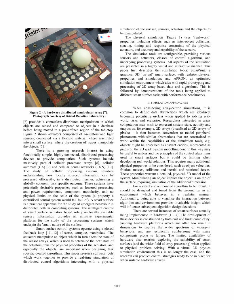
[6] provides a contactless distributed manipulation in which objects are sensed and compared to objects in a database before being moved to a pre-defined region of the tabletop. Figure 2 shows actuators comprised of oscillators and light sensors, connected via a flexible material where assembled into a small surface, where the creation of waves manipulate the objects [7].
There is a growing research interest in using functionally simple, highly-connected, distributed processing devices to provide computation. Such systems include massively parallel cellular processor arrays [8], cellular automata (CA) [9] and cellular neural networks (CNN) [10]. The study of cellular processing systems involves understanding how locally sourced information can be processed efficiently, in a distributed manner, achieving a globally coherent, task specific outcome. These systems have potentially desirable properties, such as lowered processing and power requirements, component modularity, and no physical limits on the scale of the system (a property a centralised control system would fall foul of). A smart surface is a practical apparatus for the study of emergent behaviour in distributed cellular computing systems. The intelligent control of smart surface actuators based solely on locally available sensory information provides an intuitive experimental platform for the study of the processing systems which underpin the 'smart' nature of the surface.
Smart surface control systems operate using a closed feedback loop [11, 12] of sense, compute, manipulate. The actuators manipulate an object which in turn alters the state of the sensor arrays, which is used to determine the next state of the actuators, thus the physical properties of the actuators, and especially the objects, are important when designing task specific control algorithms. This paper presents software tools which work together to provide a real-time simulation of distributed control algorithms interacting with a physical
simulation of the surface, sensors, actuators and the objects to be manipulated.
The physical simulation (Figure 1) uses ‘real-world’ properties including effects such as inter-object collisions, spacing, timing and response constraints of the physical actuators, and accuracy and capability of the sensors.
The simulation tools are configurable, providing various sensors and actuators, classes of control algorithm, and underlying processing systems. All aspects of the simulation are presented in a highly visual and interactive manner. This paper first describes the simulation tools: SmartSurf, a graphical 3D ‘virtual’ smart surface, with realistic physical properties and simulation; and APRON, an optimised simulation environment which aids with rapid prototyping and processing of 2D array based data and algorithms. This is followed by demonstrations of the tools being applied to different smart surface tasks with performance benchmarks.
II. SIMULATION APPROACHES
When considering array-centric simulations, it is common to define data abstractions which are idealised, becoming potentially useless when applied to solving real-world tasks and scenarios. Researchers interested in array computation may wish to represent system state, activity and outputs as, for example, 2D arrays (visualised as 2D arrays of pixels) – it then becomes convenient to model peripheral phenomena with similar abstractions that are constrained to work within the capabilities of the simulation tools, e.g. objects might be described as abstract entities, represented as pixels on the 2D grid. System modelling done in this way may be useful to understand the principles of the control algorithms used in smart surfaces but it could be limiting when developing real world solutions. This requires many additional physical properties to be considered, such as object velocities, friction, masses, collisions and inertial and rotational forces. These properties warrant a detailed, physical, 3D model of the system. Manipulating an object implies the object is on top of the surface, requiring simulation of the additional dimension.
For a smart surface control algorithm to be robust, it should be designed and tuned from the ground up in an environment which behaves in a realistic manner. Additionally, being able to visualise the interaction between algorithm and environment provides invaluable insight which will influence subsequent algorithm design decisions.
There are several instances of smart surfaces actually being implemented in hardware [1 - 7]. The development of these devices is constrained by both cost and build complexity, yielding hardware platforms which are often too small in dimensions to capture the wider spectrum of emergent behaviour, and are technically cumbersome with many components prone to failure. The limited availability of hardware also restricts exploring the suitability of smart surfaces (and the wider field of array processing) when applied to physical problem solving. With a virtual 3D physics simulation environment this is no longer the case, and the research can produce control strategies ready to be in place for when suitable hardware arrives.
Figure 2 - A hardware distributed manipulator array [7]. Photograph courtesy of Bristol Robotics Laboratory
445744574457
III. SMARTSURF
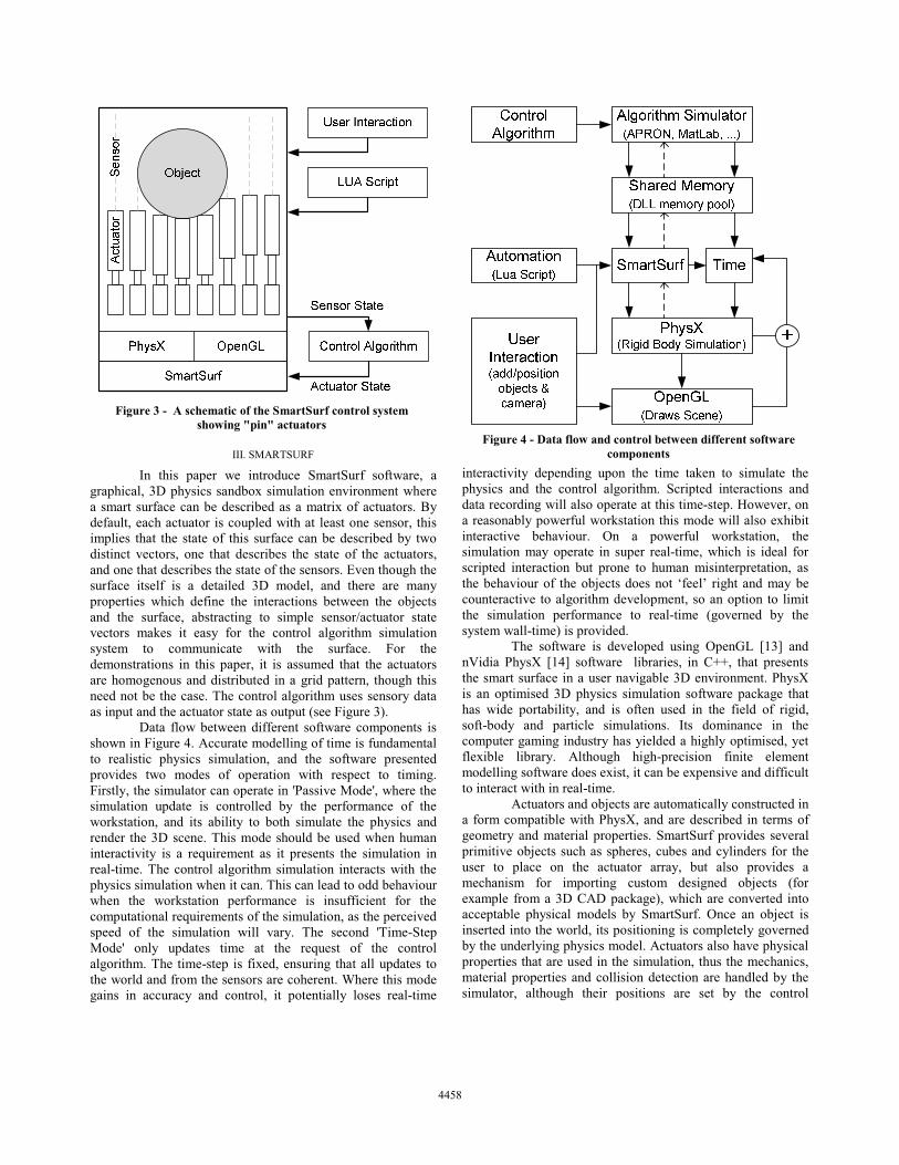
In this paper we introduce SmartSurf software, a graphical, 3D physics sandbox simulation environment where a smart surface can be described as a matrix of actuators. By default, each actuator is coupled with at least one sensor, this implies that the state of this surface can be described by two distinct vectors, one that describes the state of the actuators, and one that describes the state of the sensors. Even though the surface itself is a detailed 3D model, and there are many properties which define the interactions between the objects and the surface, abstracting to simple sensor/actuator state vectors makes it easy for the control algorithm simulation system to communicate with the surface. For the demonstrations in this paper, it is assumed that the actuators are homogenous and distributed in a grid pattern, though this need not be the case. The control algorithm uses sensory data as input and the actuator state as output (see Figure 3).
Data flow between different software components is shown in Figure 4. Accurate modelling of time is fundamental to realistic physics simulation, and the software presented provides two modes of operation with respect to timing. Firstly, the simulator can operate in 'Passive Mode', where the simulation update is controlled by the performance of the workstation, and its ability to both simulate the physics and render the 3D scene. This mode should be used when human interactivity is a requirement as it presents the simulation in real-time. The control algorithm simulation interacts with the physics simulation when it can. This can lead to odd behaviour when the workstation performance is insufficient for the computational requirements of the simulation, as the perceived speed of the simulation will vary. The second 'Time-Step Mode' only updates time at the request of the control algorithm. The time-step is fixed, ensuring that all updates to the world and from the sensors are coherent. Where this mode gains in accuracy and control, it potentially loses real-time
interactivity depending upon the time taken to simulate the physics and the control algorithm. Scripted interactions and data recording will also operate at this time-step. However, on a reasonably powerful workstation this mode will also exhibit interactive behaviour. On a powerful workstation, the simulation may operate in super real-time, which is ideal for scripted interaction but prone to human misinterpretation, as the behaviour of the objects does not ‘feel’ right and may be counteractive to algorithm development, so an option to limit the simulation performance to real-time (governed by the system wall-time) is provided.
The software is developed using OpenGL [13] and nVidia PhysX [14] software libraries, in C++, that presents the smart surface in a user navigable 3D environment. PhysX is an optimised 3D physics simulation software package that has wide portability, and is often used in the field of rigid, soft-body and particle simulations. Its dominance in the computer gaming industry has yielded a highly optimised, yet flexible library. Although high-precision finite element modelling software does exist, it can be expensive and difficult to interact with in real-time.
Actuators and objects are automatically constructed in a form compatible with PhysX, and are described in terms of geometry and material properties. SmartSurf provides several primitive objects such as spheres, cubes and cylinders for the user to place on the actuator array, but also provides a mechanism for importing custom designed objects (for example from a 3D CAD package), which are converted into acceptable physical models by SmartSurf. Once an object is inserted into the world, its positioning is completely governed by the underlying physics model. Actuators also have physical properties that are used in the simulation, thus the mechanics, material properties and collision detection are handled by the simulator, although their positions are set by the control
Figure 4 - Data flow and control between different software components
Figure 3 - A schematic of the SmartSurf control system showing "pin" actuators
445844584458
algorithm. Sensors are non-physical objmechanically interact with anything in the The directional proximity sensor for examplethe distance from the origin of the sensor, alountil it reaches an intersection point. If no there are no objects detected by the sensorintersect can then be queried for other prcolour (and even object type) extending the sensory information available to the algorithm
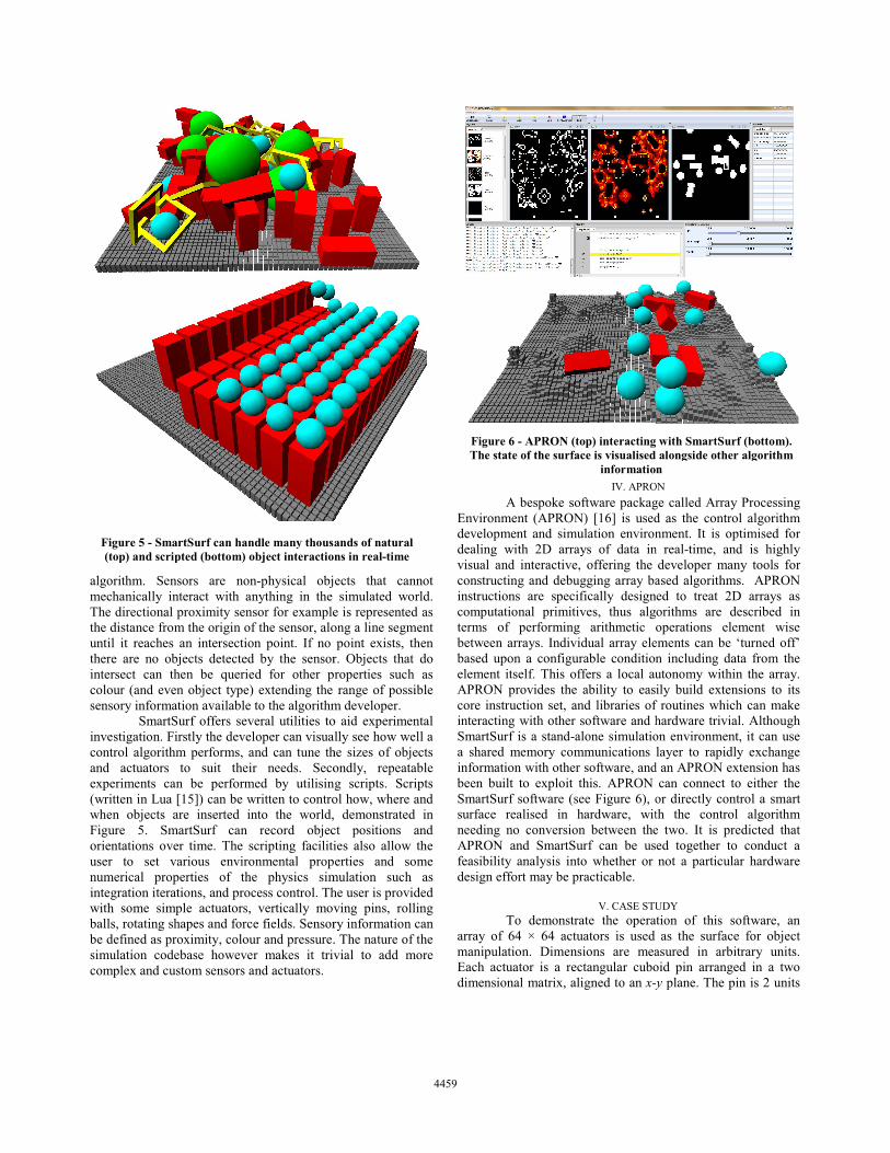
SmartSurf offers several utilities toinvestigation. Firstly the developer can visualcontrol algorithm performs, and can tune thand actuators to suit their needs. Secoexperiments can be performed by utilisin(written in Lua [15]) can be written to controwhen objects are inserted into the world, Figure 5. SmartSurf can record objecorientations over time. The scripting facilitiuser to set various environmental propnumerical properties of the physics simintegration iterations, and process control. Thwith some simple actuators, vertically movballs, rotating shapes and force fields. Sensorbe defined as proximity, colour and pressure.simulation codebase however makes it trivcomplex and custom sensors and actuators.
Figure 5 - SmartSurf can handle many thousa(top) and scripted (bottom) object interaction
ects that cannot simulated world.
e is represented as ong a line segment point exists, then
r. Objects that do roperties such as range of possible
m developer. o aid experimental lly see how well a
he sizes of objects ondly, repeatable g scripts. Scripts ol how, where and demonstrated in
ct positions and ies also allow the erties and some
mulation such as he user is provided ving pins, rolling ry information can . The nature of the vial to add more
IV. APRO A bespoke software packag
Environment (APRON) [16] is useddevelopment and simulation environdealing with 2D arrays of data invisual and interactive, offering the constructing and debugging array bainstructions are specifically designcomputational primitives, thus algterms of performing arithmetic obetween arrays. Individual array elebased upon a configurable conditionelement itself. This offers a local auAPRON provides the ability to eascore instruction set, and libraries ofinteracting with other software and hSmartSurf is a stand-alone simulatioa shared memory communications information with other software, andbeen built to exploit this. APRON SmartSurf software (see Figure 6), osurface realised in hardware, witneeding no conversion between theAPRON and SmartSurf can be usfeasibility analysis into whether or design effort may be practicable.
V. CASE STU
To demonstrate the operaarray of 64 × 64 actuators is used manipulation. Dimensions are meaEach actuator is a rectangular cubodimensional matrix, aligned to an x-y
ands of natural ns in real-time
Figure 6 - APRON (top) interactingThe state of the surface is visualised
informatioON ge called Array Processing d as the control algorithm nment. It is optimised for
n real-time, and is highly developer many tools for ased algorithms. APRON
ned to treat 2D arrays as orithms are described in operations element wise
ements can be ‘turned off’ n including data from the utonomy within the array. ily build extensions to its
f routines which can make hardware trivial. Although on environment, it can use layer to rapidly exchange
d an APRON extension has can connect to either the
or directly control a smart th the control algorithm e two. It is predicted that ed together to conduct a not a particular hardware
UDY tion of this software, an as the surface for object
asured in arbitrary units. oid pin arranged in a two y plane. The pin is 2 units
with SmartSurf (bottom). alongside other algorithm
n
445944594459
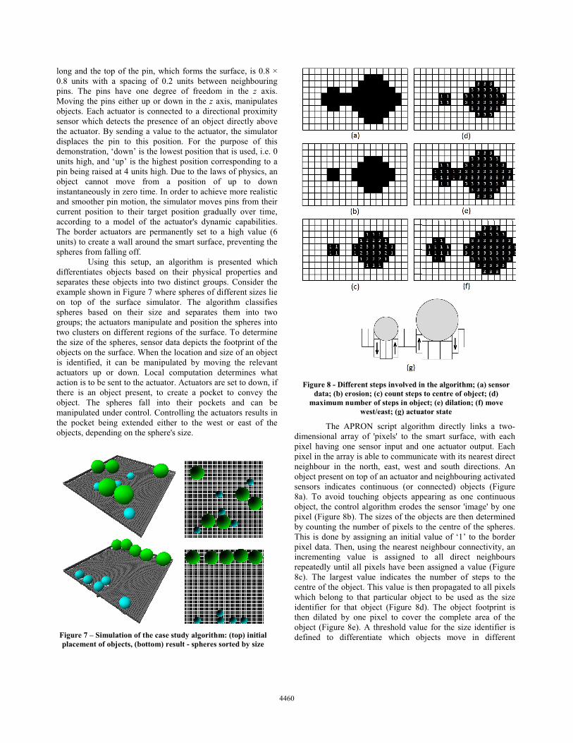
long and the top of the pin, which forms the0.8 units with a spacing of 0.2 units betwpins. The pins have one degree of freedoMoving the pins either up or down in the z objects. Each actuator is connected to a diresensor which detects the presence of an objthe actuator. By sending a value to the actuadisplaces the pin to this position. For thedemonstration, ‘down’ is the lowest position units high, and ‘up’ is the highest position cpin being raised at 4 units high. Due to the laobject cannot move from a position oinstantaneously in zero time. In order to achiand smoother pin motion, the simulator movcurrent position to their target position graaccording to a model of the actuator's dynThe border actuators are permanently set tounits) to create a wall around the smart surfaspheres from falling off. Using this setup, an algorithm is differentiates objects based on their physicseparates these objects into two distinct groexample shown in Figure 7 where spheres ofon top of the surface simulator. The algspheres based on their size and separategroups; the actuators manipulate and positiotwo clusters on different regions of the surfathe size of the spheres, sensor data depicts thobjects on the surface. When the location andis identified, it can be manipulated by moactuators up or down. Local computation action is to be sent to the actuator. Actuators there is an object present, to create a pockobject. The spheres fall into their pockmanipulated under control. Controlling the athe pocket being extended either to the weobjects, depending on the sphere's size.
Figure 7 – Simulation of the case study algorithplacement of objects, (bottom) result - spheres
e surface, is 0.8 × ween neighbouring om in the z axis.
axis, manipulates ectional proximity ect directly above ator, the simulator e purpose of this that is used, i.e. 0
corresponding to a aws of physics, an of up to down ieve more realistic
ves pins from their adually over time, namic capabilities. o a high value (6 ace, preventing the
presented which cal properties and oups. Consider the f different sizes lie gorithm classifies s them into two n the spheres into ace. To determine he footprint of the d size of an object
oving the relevant determines what
are set to down, if ket to convey the kets and can be actuators results in est or east of the The APRON script algorit
dimensional array of 'pixels' to the pixel having one sensor input and pixel in the array is able to communineighbour in the north, east, west object present on top of an actuator asensors indicates continuous (or co8a). To avoid touching objects appobject, the control algorithm erodes pixel (Figure 8b). The sizes of the obby counting the number of pixels toThis is done by assigning an initial pixel data. Then, using the nearest nincrementing value is assigned trepeatedly until all pixels have been8c). The largest value indicates thecentre of the object. This value is thewhich belong to that particular objeidentifier for that object (Figure 8dthen dilated by one pixel to cover object (Figure 8e). A threshold valudefined to differentiate which obhm: (top) initial
s sorted by size
Figure 8 - Different steps involved indata; (b) erosion; (c) count steps
maximum number of steps in objewest/east; (g) actua
thm directly links a two-smart surface, with each
one actuator output. Each icate with its nearest direct and south directions. An
and neighbouring activated onnected) objects (Figure pearing as one continuous
the sensor 'image' by one bjects are then determined the centre of the spheres. value of ‘1’ to the border
neighbour connectivity, an to all direct neighbours n assigned a value (Figure e number of steps to the en propagated to all pixels ect to be used as the size d). The object footprint is
the complete area of the ue for the size identifier is bjects move in different
n the algorithm; (a) sensor to centre of object; (d)
ect; (e) dilation; (f) move ator state
446044604460

directions. Pixels associated with an object with a size identifier smaller than the threshold (threshold value of 2 is assumed in the example in Figure 8) are moved to the west. Pixels associated with an object with a size identifier larger than the threshold are moved to the east (Figure 8f). The actuators are moved 'up' or 'down' according to the new locations of the object pixels (Figure 8g) which results in objects being pushed laterally across the surface. As the spheres move to a new resting position (due to gravity) and the sensor data is re-evaluated, the algorithm continues to move the different objects in opposite directions until they reach the raised actuators at edge of the surface preventing them from falling off. It is important to emphasize that the presented algorithm can be implemented in a distributed computing system of locally connected, near-sensor processing units; at no point is a list of objects maintained, instead the information about the objects and their locations is represented by the state of the surface. This algorithm is not affected by object collisions when spheres attempt to move in opposite directions. Due to the erosion that takes place on the sensor data to separate touching objects, the touching objects will continue to push against one another, until one is moved out of the way. The performance on the algorithm can be evaluated by recording the trajectories of all objects in the simulation as shown in Figure 9. The algorithm constantly re-evaluates the sensor data, and eventually the spheres pass each other to form clusters in different regions of the smart surface. This can be demonstrated effectively by placing a large quantity of spheres on the smart surface, as in Figure 7. Even though multiple spheres are placed on the surface and collisions occur, because the sensor data is constantly re-evaluated, and the spheres' physical dynamics are modelled accurately, the spheres can be separated based on their size.
The objects being spherical naturally aids in manipulation and collision resolution, a more sophisticated manipulation strategy would be necessary for non-spherical objects.
VI. CONCLUSION
This paper has presented a realistic simulation environment for the development of smart surfaces, alongside software for the real-time interaction, development, visualisation and debugging of the control algorithms used to drive them. Such a suite of tools can be used for requirement analysis when realising a smart surface in hardware, by testing combinations of actuator and sensor designs with task specific goals. An object sorting algorithm has been demonstrated, bringing together the physical and control algorithm simulations, using data from the simulation as empirical proof of its effectiveness. It is hoped that these tools will be adopted by researchers interested in distributed computation, manipulator arrays and other array-centric phenomena.
ACKNOWLEDGEMENTS
This work has been funded by the EPSRC, grant number
EP/H023623/1. REFERENCES
[1] D. Leithinger and H. Ishii, “Relief: A scalable actuated shape display”, in Proceedings of the fourth international conference on Tangible, embedded, and embodied interaction (TEI '10), Cambridge, MA, 2010, pp. 221-222. [2] J. E. Luntz, W. Messner, and H. Choset. "Distributed manipulation using discrete actuator arrays". The Int. Journal of Robotics Research, 2001. [3] G. Pangaro, D. Maynes-Aminzade and H. Ishii, “The actuated workbench: Computer-controlled actuation in tabletop tangible interfaces”, in Proceedings of the 15th annual ACM symposium on User interface software and technology (UIST’02), Paris, France, 2002, pp. 181-190. [4] M. Weiss, F. Schwarz, S. Jakubowski, and J. Borchers. "Madgets: Actuating Widgets on Interactive Tabletops", UIST '10, pages 293-302, New York, NY, USA, 2010. [5] M. Weiss, C. Wacharamanotham, S. Voelker and J. Borchers, “FingerFlux: Near-surface haptic feedback on tabletops”, in Proceedings of the 24th annual ACM symposium on User interface software and technology (UIST’11), Santa Barbara, CA, 2011, pp. 615-620. [6] K. Boutoustous, G. J. Laurent, E. Dedu, L. Matignon, J. Bourgeois, and N. Le Fort-Piat, "Distributed control architecture for smart surfaces", IEEE Int. Conf. on Intelligent Robots and Systems, 2010. [7] I. Georgilas, A. Adamatzky and C. Melhuish, "Towards an Intelligent Distributed Conveyor", Lecture Notes in Computer Science (including subseries Lecture Notes in Artificial Intelligence and Lecture Notes in Bioinformatics), vol. 7429 LNAI, pp. 457-458. [8] A.Lopich and P.Dudek, "A SIMD Cellular Processor Array Vision Chip With Asynchronous Processing Capabilities", IEEE Transactions on Circuits and Systems - I, vol 58, issue 10, pp. 2420-2431, October 2011. [9] I. Georgilas, A. Adamatzky, and C. Melhuish, “Manipulating objects with gliders in cellular automata”, IEEE International Conference on Automation Science and Engineering (CASE), pp. 936–941, IEEE, 2012. [10] L. Chua and L. Yang, "Cellular Neural Networks: Theory," IEEE Trans. on Circuits and Systems, 35(10):1257-1272, 1988. [11] S. Skachek, A. Adamatzky, and C. Melhuish, “Manipulating planar shapes with a light-sensitive excitable medium: Computational studies of closed-loop systems” Int. J. Bifurcation Chaos, vol. 16, no. 8, 2006. [12] K. Boutoustous, G. J. Laurent, E. Dedu, L. Matignon, J. Bourgeois, and N. Le Fort-Piat, "Distributed control architecture for smart surfaces", IEEE Int. Conf. on Intelligent Robots and Systems, 2010. [13] OpenGL, http://www.opengl.org, May 2013. [14] nVidia PhysX, http:/developer.nvidia.com/physx, May 2013. [15] Lua, http://www.lua.org, May 2013. [16] D. R. W. Barr and P. Dudek, “Apron: A cellular processor array simulation and hardware design tool” EURASIP Journal on Advances in Signal Processing, vol. 2009, p. 3, 2009.
Figure 9 - Trajecctories of spheres during sorting, extracted from Smart Surf, where solid line is the small spheres and
dashed line is the large spheres. Initial locations of spheres are marked with 'O', final locations with 'X'
446144614461
Related Documents