World Applied Sciences Journal 28 (3): 353-360, 2013 ISSN 1818-4952 © IDOSI Publications, 2013 DOI: 10.5829/idosi.wasj.2013.28.03.13799 Corresponding Author: Adnan Ahmed, PCRG LAB, Level 4, N82A, Faculty of Computing, Universiti Teknologi Malaysia, Johor Bahru, Malaysia. Tel: +60163503962. 353 A Simulation Based Study of Well Known Routing Protocols for Delay Tolerant Network Adnan Ahmed, Kamalrulnizam Abu Bakar, 1 1 Muhammad Ibrahim Channa and Kashif Naseer Qureshi 2 1 Faculty of computing, Universiti Teknologi Malaysia, Skudai, Johor Bahru, Malaysia 1 Department of Information Technology, Quaid-e-Awam University of Engg: 2 Science and Technology, Nawabshah, Pakistan Abstract: Delay tolerant networks are class of wireless ad-hoc networks in which end-to-end direct path between source and destination does not exist all the time. Conventional routing techniques are not feasible due to intermittent connectivity; therefore DTN emphasis on store and forward routing mechanism. DTN provides connectivity and communication in areas such as to extend the reach of internet to space, interconnect planets and underwater communication, which were considered to be unapproachable, distant and unfriendly. In this paper performance of some well known routing protocols for DTN is measured using different mobility models, number of nodes, transmission ranges and buffer sizes and present a comparative analysis in term of variety of parameters such as delivery ratio, overhead and latency. Based on the observations derived from simulation study, we also proposed a location based algorithm called “Grid based routing algorithm” for delay tolerant network. The goal of proposed algorithm is to provide prior knowledge of network to nodes, control flooding and number of transmissions in network. Grid based algorithm use concept of location information of nodes. By having location information messages are only delivered to the neighbor that is nearer and in direction towards to the destination. Key words: Routing protocols Epidemic PROPEHT Spray and wait Grid based routing. INTRODUCTION Infrastructure-less network does not rely on access Wireless networks are becoming more famous provide communication, example includes Mobile Ad-hoc day by day, with the development of cheap Network (MANET) and Vehicular Ad hoc Network technologies and information is available anywhere (VANET) [1] as shown in Figure 2. anytime. Wireless networks have numerous applications Due to dynamic network topology, traditional in various fields, some of them are: industrial applications, internet routing protocols like distance vector and link m ilitary applications, personal area networks, state are unsuitable for ad-hoc network, which results in inter-village communication and wireless sensor networks. link instability. Therefore, different routing schemes are Wireless networks are classified as: infrastructure-based proposed for MANETS which are as: on-demand or networks and infrastructure-less networks. In reactive (DSR [2] and AODV [3]) and table driven or Infrastructure-based networks, access points or base proactive (DSDV) [4]. MANETs rely on prior end-to-end stations are responsible to provide communication connected link between nodes to forward packets. If node between mobile nodes. Examples are satellite networks, mobility is extremely high and continuous link between Wi-Fi, cellular networks and WLAN, as shown in nodes does not exist due to network partition, it becomes Figure 1. difficult to forward messages to intended destination. points, base stations or some central administration to

Welcome message from author
This document is posted to help you gain knowledge. Please leave a comment to let me know what you think about it! Share it to your friends and learn new things together.
Transcript
World Applied Sciences Journal 28 (3): 353-360, 2013ISSN 1818-4952© IDOSI Publications, 2013DOI: 10.5829/idosi.wasj.2013.28.03.13799
Corresponding Author: Adnan Ahmed, PCRG LAB, Level 4, N82A, Faculty of Computing, Universiti Teknologi Malaysia,Johor Bahru, Malaysia. Tel: +60163503962.
353
A Simulation Based Study of Well Known RoutingProtocols for Delay Tolerant Network
Adnan Ahmed, Kamalrulnizam Abu Bakar,1 1
Muhammad Ibrahim Channa and Kashif Naseer Qureshi2 1
Faculty of computing, Universiti Teknologi Malaysia, Skudai, Johor Bahru, Malaysia1
Department of Information Technology, Quaid-e-Awam University of Engg:2
Science and Technology, Nawabshah, Pakistan
Abstract: Delay tolerant networks are class of wireless ad-hoc networks in which end-to-end direct pathbetween source and destination does not exist all the time. Conventional routing techniques are not feasibledue to intermittent connectivity; therefore DTN emphasis on store and forward routing mechanism. DTNprovides connectivity and communication in areas such as to extend the reach of internet to space, interconnectplanets and underwater communication, which were considered to be unapproachable, distant and unfriendly.In this paper performance of some well known routing protocols for DTN is measured using different mobilitymodels, number of nodes, transmission ranges and buffer sizes and present a comparative analysis in term ofvariety of parameters such as delivery ratio, overhead and latency. Based on the observations derived fromsimulation study, we also proposed a location based algorithm called “Grid based routing algorithm” for delaytolerant network. The goal of proposed algorithm is to provide prior knowledge of network to nodes, controlflooding and number of transmissions in network. Grid based algorithm use concept of location information ofnodes. By having location information messages are only delivered to the neighbor that is nearer and indirection towards to the destination.
Key words: Routing protocols Epidemic PROPEHT Spray and wait Grid based routing.
INTRODUCTION Infrastructure-less network does not rely on access
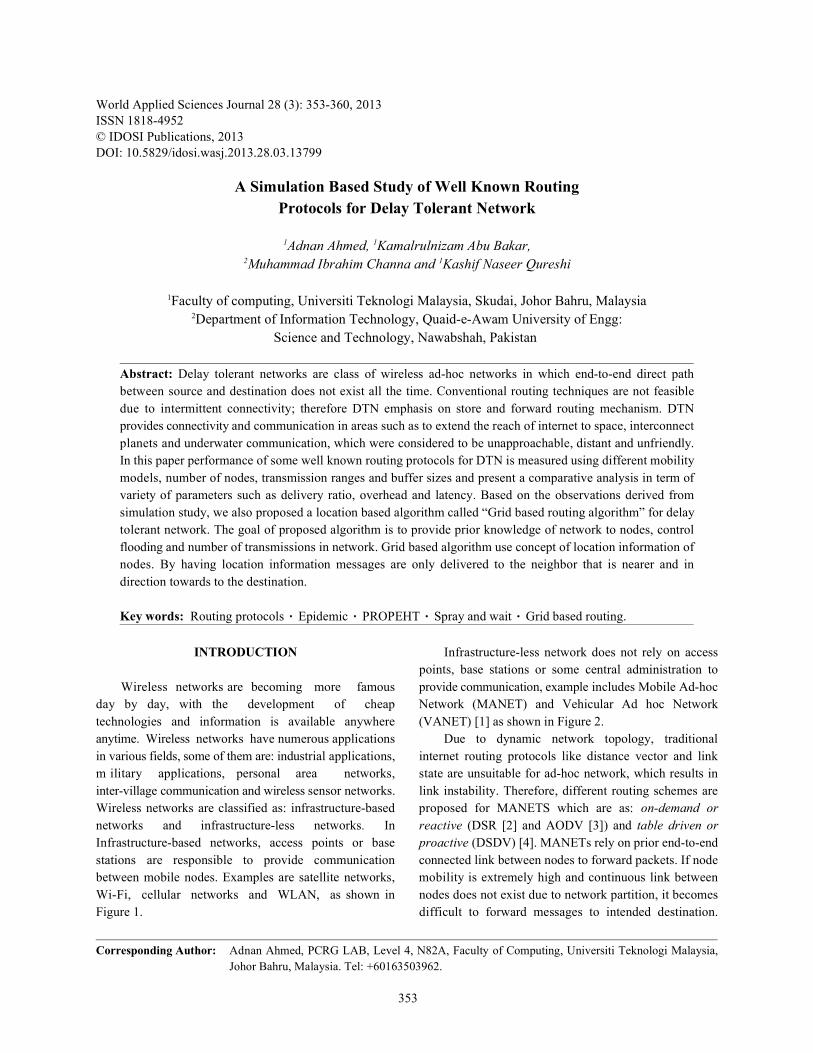
Wireless networks are becoming more famous provide communication, example includes Mobile Ad-hocday by day, with the development of cheap Network (MANET) and Vehicular Ad hoc Networktechnologies and information is available anywhere (VANET) [1] as shown in Figure 2. anytime. Wireless networks have numerous applications Due to dynamic network topology, traditionalin various fields, some of them are: industrial applications, internet routing protocols like distance vector and linkm ilitary applications, personal area networks, state are unsuitable for ad-hoc network, which results ininter-village communication and wireless sensor networks. link instability. Therefore, different routing schemes areWireless networks are classified as: infrastructure-based proposed for MANETS which are as: on-demand ornetworks and infrastructure-less networks. In reactive (DSR [2] and AODV [3]) and table driven orInfrastructure-based networks, access points or base proactive (DSDV) [4]. MANETs rely on prior end-to-endstations are responsible to provide communication connected link between nodes to forward packets. If nodebetween mobile nodes. Examples are satellite networks, mobility is extremely high and continuous link betweenWi-Fi, cellular networks and WLAN, as shown in nodes does not exist due to network partition, it becomesFigure 1. difficult to forward messages to intended destination.
points, base stations or some central administration to
World Appl. Sci. J., 28 (3): 353-360, 2013
354
is drawn in Section 5 and finally section 6 provides some
Fig. 1: Infrastructure-based network each other they exchange delivery predictability values.
Fig. 2: Mobile ad-hoc network PROPHET protocol has been successfully
These limitations gave rise to another type of network access such as email services and web access [14]. termed as Delay Tolerant Network (DTN) [5, 6] that The problem with this scheme is that as number ofexploits high node mobility and route messages among nodes increases overhead ratio also increases. Itnodes without having connected path between them. consumes a lot of resources to process and storeDTN has application in various types of networks such as historical values.VANETs, inter-planetary networks (IPN), underwaternetworks, terrestrial networks, WSN and military networks Epidemic Protocol: Epidemic protocol [15] is flooding[7, 8]. based protocol to solve routing issues for DTN. A node
The rest of this paper is organized as follows: with flooding nature forwards message to every otherSection 2 discusses the concepts of some well known node it meet. Epidemic protocol makes use of carrierrouting protocols for DTN. Section 3 presents the nodes to deliver messages between source andsimulation results and comparative analysis of these destination. Epidemic protocol works on the assumption
protocols under four different scenarios and performanceis measured with different parameters. Section 4 providesproposed routing algorithm with discussions. Conclusion
indications of future research.
Literature Review: routing techniques, with varyingcharacteristics, are proposed by different researchers. Inthis section we review routing in DTN and presentscommon DTN routing protocols.
PROPHET Protocol: PROPHET is a Probabilistic RoutingProtocol using History of Encounters and Transitivity[9, 10]. While delivering messages there might be somenodes that meets each other on regular basis and theremight be some nodes that do not or quite often meet eachother. PROPHET exploits this assumption and allocatesprobability metric value called delivery predictability toeach node as high, medium and low according to numberof contacts they made. Whenever two nodes encounter
If two nodes do not have any contact or very rare contact,a low predictability value is assigned to them. A mediumvalue is assigned if numbers of contacts are less frequentand delivery predictability value is high if two nodesencounter each other on regularly basis. PROPHET alsohas transitivity property and it states that if node Xregularly meets Y and node Y regularly meets node Z,therefore Z is a suitable node for X, therefore X marks Z’sdelivery predictability value as high in its summary vector[11]. PROPHETv2 [12] is the improved and modifiedversion of PROPHET which maintain original ideas anddesign with only modifications in delivery predictabilityand transitivity updates [13].
implemented in northern Sweden to provide Internet
World Appl. Sci. J., 28 (3): 353-360, 2013
355
that sender of message do not have any prior information itself until it encounter destination node. This schemeabout location of nodes and network topology. For does not consume a lot of resources (bandwidth andexample a source node S, wanted to send a message to a buffer space) as other protocols do [20]. The delivery ratiodestination node D, without having connected path for this scheme is not so high because of abovebetween them. S flood out the messages to its two mentioned fact but it is one of the simples routingneighbors, N1 and N2, that are in direct transmission schemes.range of S. After some time T, N2 moves toward anotherhost N3 and transmits the message to it. N3 is in RESULTStransmission range of destination and finally sends themessage to it. Opportunistic Network Environment (ONE) [21]
This scheme guarantees the delivery of data with simulator has been used to analyze the performance ofhigh probability but it suffers from high network traffic well known routing protocols for DTN. ONE joinsbecause of high numbers of transmission on network. together movement models, routing simulation, reportingEpidemic consumes a lot of network resources such as and visualization at single platform.buffer space and bandwidth. In this section, performance of PROPEHT, Epidemic
This scheme is suitable for the animal monitoring and spray and wait is analyzed under four differentnetworks such as ZebraNet and SWIN, where nodes scenarios such as mobility models, transmission range,follow random mobility pattern and contacts cannot be number of nodes and buffer size. Performance is measuredpredicted [16, 17]. in terms of delivery ratio, average latency and overhead
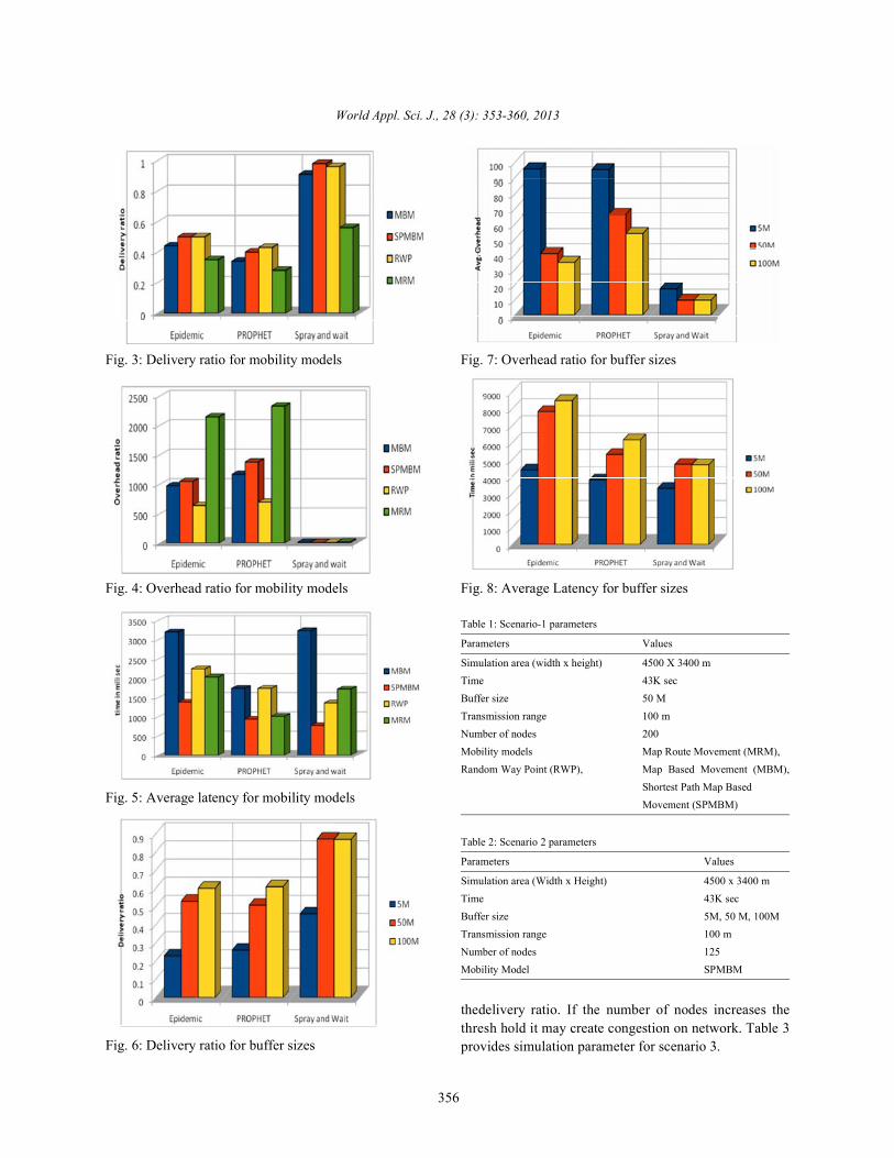
Spray and Wait Protocol: Flooding schemes experiencethe drawback of high network congestion and consumes Scenario 1: Mobility Models: A mobility model decidesa lot of energy and bandwidth while routing messages how the nodes move in the network for the period of[13]. To cope with these limitations, spray and wait simulation. Table 1 shows the simulation parameters forrouting scheme was introduced. To avoid flooding scenario 1.behavior in this scheme; a threshold value has been Figure 3, 4 and 5 shows the comparison of deliverydefined on number of copies per message that are ratio, overhead and latency respectively in variousexchanged among nodes. mobility models. It is clear from the results SPMBM
It comprises of two phases called: Spray phase and performs well than other models as it tries to route dataWait phase [18]. Spray phase says that sender node can through shortest path, it has high delivery ratio whileonly forward L number of copies instead of forwarding overhead and latency are low.copy to every node encounter. L is the limit imposed byprotocol that restricts wild flooding of messages in Scenario 2: Buffer Sizes: Routing protocol exhibitsnetwork. Wait phase says that each intermediate node different behaviors if the buffer size of node is varied. Asthat has copy of message must hold message with itself the node has limited buffer space there are more chancesuntil it encounters destination node. Intermediate node that packets will drop and affects the overall deliverywill not pass copy of message to some another node it ratio. Table 2 provides the parameters for scenario 2.encounter other than destination. Figure 6, 7 and 8 shows the results of various buffer
From authors point of view [18, 19] this scheme sizes. As the buffer size increases nodes have enoughprovides improved performance with respect to delay, space to hold the packets therefore packet drop ratio willoverhead and delivery ratio under high network traffic. be reduced and delivery ratio will be increased. The
It is robust and scalable, retaining its performance overall overhead is minimized with the increase of bufferadvantage over a large range of scenarios. It suffers from size because nodes do not need to perform extrathe drawback that relay node waits until it encounters the computations to decide which messages to be hold indestination. This may result in dropping of packet if TTL buffer. Although latency of epidemic and PROPEHT isexpires. high due to flooding base nature of protocols.
Direct Contact: In this scheme source node is responsible Scenario 3: Number Of Nodes: As the number of nodesfor routing messages to destination node without relying increases in the network, more nodes has chance to be theon intermediate nodes. Nodes keep the message with part of routing. To a certain threshold it increases
ratio.
World Appl. Sci. J., 28 (3): 353-360, 2013
356
Fig. 3: Delivery ratio for mobility models Fig. 7: Overhead ratio for buffer sizes
Fig. 4: Overhead ratio for mobility models Fig. 8: Average Latency for buffer sizes
Fig. 5: Average latency for mobility models
Fig. 6: Delivery ratio for buffer sizes
Table 1: Scenario-1 parameters
Parameters Values
Simulation area (width x height) 4500 X 3400 mTime 43K secBuffer size 50 MTransmission range 100 mNumber of nodes 200Mobility models Map Route Movement (MRM),Random Way Point (RWP), Map Based Movement (MBM),
Shortest Path Map BasedMovement (SPMBM)
Table 2: Scenario 2 parameters
Parameters Values
Simulation area (Width x Height) 4500 x 3400 mTime 43K secBuffer size 5M, 50 M, 100MTransmission range 100 mNumber of nodes 125Mobility Model SPMBM
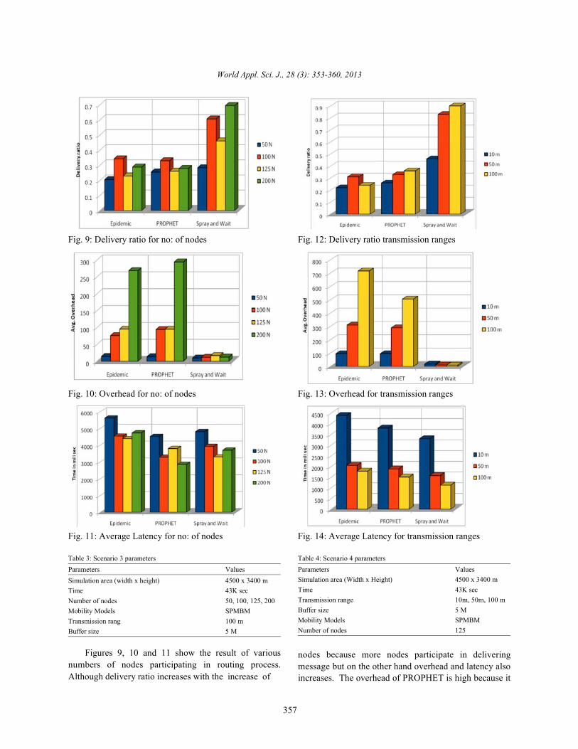
thedelivery ratio. If the number of nodes increases thethresh hold it may create congestion on network. Table 3provides simulation parameter for scenario 3.
World Appl. Sci. J., 28 (3): 353-360, 2013
357
Fig. 9: Delivery ratio for no: of nodes Fig. 12: Delivery ratio transmission ranges
Fig. 10: Overhead for no: of nodes Fig. 13: Overhead for transmission ranges
Fig. 11: Average Latency for no: of nodes Fig. 14: Average Latency for transmission ranges
Table 3: Scenario 3 parameters Table 4: Scenario 4 parametersParameters Values Parameters ValuesSimulation area (width x height) 4500 x 3400 mTime 43K secNumber of nodes 50, 100, 125, 200Mobility Models SPMBMTransmission rang 100 mBuffer size 5 M
Figures 9, 10 and 11 show the result of variousnumbers of nodes participating in routing process.Although delivery ratio increases with the increase of
Simulation area (Width x Height) 4500 x 3400 mTime 43K secTransmission range 10m, 50m, 100 mBuffer size 5 MMobility Models SPMBMNumber of nodes 125
nodes because more nodes participate in deliveringmessage but on the other hand overhead and latency alsoincreases. The overhead of PROPHET is high because it
World Appl. Sci. J., 28 (3): 353-360, 2013
358
has to keep track of past encounters and compute possible to predict the location of node. In grid baseddelivery predictabilities values of nodes. To a certain algorithm, to assist routing process GPS receiver is usedthreshold value latency is reduced but with the to predict current position of source node, position ofintroduction of more nodes it also creates congestion on next hop neighbor and position of destination.network due to which latency rate also increases. In GBR, two-level hierarchical routing is performed i-
Scenario 4: Transmission ranges: Increased in information is shared only between the nodes that are thetransmission range also increases number of contacts part of grid, while in inter-grid routing, information isamong nodes, as more nodes comes in coverage area. shared between the grid leader nodes of two differentTable 4 shows the simulation parameters for scenario 4. grids. Within every grid, a grid leader node is elected
Figures 12, 13 and 14 show the result of varies that plays vital role in routing messages. The election oftransmission ranges. As transmission range increases leader node is dynamic process, it depends on the numbermore nodes come in contact with each other and of contacts a node have with the grid in direction towardsfacilitating the message delivery therefore delivery ratio destination. Therefore a separate table has to bewill be high and latency will be reduced. The overhead of maintained that records number of contacts a nodeepidemic and PROPHET increases due to flooding based made with other neighbor nodes. The majornature and computational overhead respectively. responsibilities of leader node are: to collect data packets
Simulation results shows spray and wait outperforms from local grid and sends them to neighboring grid leaderPROPHET and epidemic in mentioned scenarios. But the node, exchanging hello messages with neighbor leaderone of the drawback of all these protocols is that none of and maintain list of nodes that can be reach directly orthe node has knowledge about network. This lack of indirectly.ability makes them unsuitable for surveillance, tactical andemergency applications, where it is required to have The Grid Based Routing Algorithm Is Given as Follows:knowledge about network, positions of neighbor anddestination nodes to be known in order to deliver Step 1: Grid leader election. The node in a grid that hasmessages in timely and accurately manner. By keeping higher number of contact with other gird nodes towardsthis in mind grid based routing algorithm is proposed in destination is elected as grid leader.section 4.
Proposed Location Based Algorithm: The proposedlocation based algorithm is called “Grid based routing { If Number of contacts [N] > Number of contacts [A]algorithm” (GBR). In GBR, physical area is partitioned into THEN G = Nx,y}two dimensional logical squares of rows and columns,called grid. It is assumed that each node has complete Whereknowledge of network that includes information of currentlocation, location information of neighbor nodes in grid G is the grid leader node in current gridand location information of destination nodes. One of thefundamental assumptions in grid based routing is that Step 2: Compute the grid distance between current grideach node is equipped with GPS receiver. Nowadays (G ) and destination grid (G ), called it d .GPS-related applications are attracting more attention andpopularity such applications includes tour guide Step 3: Compute grid distance between neighbor gridsystems, telematic systems and navigation system [22]. (G ) and destination grid (G ), called .
Routing protocols discussed in section 2 suffers fromthe problem of congestion, inefficient use of resources Step 4: Compare d and d , if d is less than d thensuch as bandwidth and long delays due to no knowledge assign value of d to d and assign G to G .about the network. In order to overcome these problemsand give location aware facility to routing process, “Grid Step 5: Repeat step3 and step 4 until the next suitable gridbased routing algorithm” is proposed. With the that has direction towards destination and smalleravailability of GPS based systems it’s now become distance than other grids is selected.
e intra-grid and inter-grid. In intra-grid routing,
GRID_LEADER (N, X, Y)
x,y
x,y .
cur dest curr
neib dest neib
neib curr neib curr
neib curr neib next
World Appl. Sci. J., 28 (3): 353-360, 2013
359
Step 6: Return the coordinates of next grid G 5. Burleigh, S., A. Hooke, L. Torgerson, K. Fall,next.
CONCLUSION Delay-tolerant Networking: An Approach to
The major objective of delay tolerant networks is to pp: 128-136.provide connectivity is those regions that are not 6. Fall, K., 2003. A delay-tolerant network architectureaccessible. Conventional routing protocols are not for challenged internets. In Proceedings of thesuitable for DTN as they rely on to always have conference on Applications, technologies,connected path between two nodes before data architectures and Protocols for Computertransmission begins. Therefore, to efficiently route Communications, pp: 27-34.messages between nodes is become one of the key 7. Warthman, F., 2003. Delay-tolerant networks (DTNs):research areas. In this paper, well known routing A Tutorialprotocols for DTN are simulated under four different 8. Demmer, M. and K. Fall. DTLSR: Delay Tolerantscenarios. Simulation results shows that spray and wait Routing for Developing Regions. In Proceedings ofrouting protocol outperforms epidemic and PROPHET due the 2007 Workshop on Networked Systems forto its simple designs, robustness and scalability. But all of Developing Regions, pp: 5.above mentioned protocols are not suitable for 9. Anders Lindgren, Doctoral Thesis. Routing andsurveillance and emergency applications due to lack of Quality of Service in Wireless and Disruptionnetwork knowledge. Therefore grid based routing Tolerant Networks, June 2006.algorithm is proposed, that make use of location 10. Lindgren, A., A. Doria and O. Schelén, 2003.information of nodes to route messages. This work could Probabilistic Routing in Intermittently Connectedbe enhanced by implementing and simulating grid based Networks. ACM SIGMOBILE Mobile Computing androuting algorithm. The performance of grid based routing Communications, pp: 19-20.algorithm will be analyzed in different mobility models and 11. Haris, Abdullah. A DTN Study Analysis ofalso work is in progress to develop a scenario model that Implementations and Tools, Master's Thesis Espoo,is more applicable for emergency and surveillance based July 30, 2010.applications. Security issues also need to be addressed in 12. Grasic, S., E. Davies, A. Lindgren and A. Doria, 2011.order to be aware of malicious nodes in network. “The evolution of a DTN routing protocol-Therefore security issues related to malicious nodes will PRoPHETv2,” in Proceedings of the 6th ACMalso be incorporated with grid based routing algorithm. workshop on Challenged networks, pp: 27-30.
REFERENCES D. Keykhosravi, 2011. "Energy-efficient and Real
1. Qureshi, Kashif Naseer and Abdul Hanan Abdullah. World Appl. Sci. J."WASJ ."Study of Efficient Topology Based Routing 14. Doria, A., M. Uden and D.P. Pandey, 2002. ProvidingProtocols for Vehicular Ad-Hoc Network Connectivity to the Saami Nomadic Community. InTechnology. "World Applied Sciences Journal, Development by Design Conference.23(5): 656-663. 15. Vahdat, A. and D. Becker, 2000. Epidemic Routing for
2. Johnson, D.B. and D.A. Maltz, 1996. Dynamic Source Partially Connected Ad Hoc Networks: TechnicalRouting in Ad Hoc Wireless Networks. Mobile Report CS-200006. Duke University.Computing, pp: 353. Kluwer Academic Publishers. 16. Suganthe, R.C. and P. Balasubramanie, 2008. Efficient
3. Charles Perkins and Elizabeth Royer. Ad hoc on Routing For Intermittently Connected Mobile Ad hocdemand distance vector routing. In Proceedings of Network, IJCSNS 8, 184.the 2nd IEEE Workshop on Mobile Computing 17. Spyropoulos, T., K. Psounis and C.S. Raghavendra,Systems and Applications, pages 90-100, February 2005. Single-copy Routing in Intermittently1999. Connected Mobile Networks. In Sensor and Ad Hoc
4. Perkins, C. and P. Bhagwat, 1994. Highly Dynamic Communications and Networks, 2004. IEEE SECONDestination-sequenced Distance-vector Routing. In 2004. 2004 First Annual IEEE CommunicationsProc. of the ACM SIGCOMM, October, 1994. Society Conference On, pp: 235-244.
V. Cerf, B. Durst, K. Scott and H. Weiss, 2003.
Interplanetary Internet. Communications Magazine,
13. Ghaffari, A., H. Rahbari Bannaeian and
time Routing Protocol for Wireless Sensor Networks,
World Appl. Sci. J., 28 (3): 353-360, 2013
360
18. Spyropoulos, T., K. Psounis and C.S. Raghavendra, 20. Jones, E.P. and P.A. Ward, 2006. Routing Strategies2005. Spray and Wait: An Efficient Routing Scheme for Delay-tolerant Networks. Submitted to Computerfor Intermittently Connected Mobile Networks. In Communication Review.Proceedings of the 2005 ACM SIGCOMM Workshop 21. Keranen, A., J. Ott and T. Karkkainen, 2009. The ONEon Delay-tolerant Networking, pp: 252-259. Simulator for DTN Protocol Evaluation. In
19. Spyropoulos, T., K. Psounis and C.S. Raghavendra, Proceedings of the 2nd International Conference on2007. Spray and focus: Efficient mobility-assisted Simulation Tools and Techniques, pp: 1-10.routing for heterogeneous and correlated mobility. In 22. Liao, W.H., J.P. Sheu and Y.C. Tseng, 2001. GRID: APervasive Computing and Communications Fully Location-aware Routing Protocol for MobileWorkshops, 2007. PerCom Workshops' 07. Fifth Ad Hoc Networks. Telecommunication Systems,Annual IEEE International Conference on, pp: 79-85. 18: 37-60.
Related Documents