JOURNAL OF SOUND AND VIBRATION Journal of Sound and Vibration 305 (2007) 432–456 A simplified model to explore the root cause of stick–slip vibrations in drilling systems with drag bits Thomas Richard a , Christophe Germay b , Emmanuel Detournay c, a CSIRO Petroleum, Technology Park Kensington, 6151 WA, Australia b Institut d’Electricite´Monte´fiore, University of Lie`ge, B-4000 Lie`ge, Belgium c Department of Civil Engineering, University of Minnesota, Minneapolis, MN 55455, USA Received 5 October 2005; received in revised form 2 April 2007; accepted 4 April 2007 Available online 13 June 2007 Abstract In this paper a study of the self-excited stick–slip oscillations of a rotary drilling system with a drag bit, using a discrete model that takes into consideration the axial and torsional vibration modes of the system, is described. Coupling between these two vibration modes takes place through a bit–rock interaction law, which accounts for both the frictional contact and the cutting processes. The cutting process introduces a delay in the equations of motion that is responsible for the existence of self-excited vibrations, which can degenerate into stick–slip oscillations and/or bit bouncing under certain conditions. From analysis of this new model it is concluded that the experimentally observed decrease of the reacting torque with the angular velocity is actually an expression of the system response, rather than an intrinsic rate dependence of the interface laws between the rock and the drill bit, as is commonly assumed. r 2007 Elsevier Ltd. All rights reserved. 1. Introduction Rotary drilling systems used to drill deep boreholes for hydrocarbon exploration and production often experience severe torsional vibrations, called stick–slip, characterized by (i) sticking phases where the bit stops, and (ii) slipping phases where the angular velocity of the tool O increases up to two times the imposed angular velocity. This problem is particularly acute with drag bits, which consist of fixed blades or cutters mounted on the surface of a bit body. The stick–slip phenomenon has been the subject of intensive research in various fields of mechanics [1,2], ranging from the triggering of earthquakes [3–5] to the squealing of brakes [6]. It is usually assumed that the cause of stick–slip lies within the constitutive properties of the frictional interface, and in particular through the dependence of the coefficient of friction m on the relative velocity ½v between the two contacting surfaces. In fact, stick–slip oscillations are classically modeled on the basis of a friction coefficient decreasing with ½v, as observed in some experiments [7–9]. Indeed, a sufficient condition to trigger instability of steady sliding is simply qm=q½vo0 in the neighborhood of the trivial solution [10]. Due to this velocity-weakening property, the ARTICLE IN PRESS www.elsevier.com/locate/jsvi 0022-460X/$ - see front matter r 2007 Elsevier Ltd. All rights reserved. doi:10.1016/j.jsv.2007.04.015 Corresponding author. Tel.: +1 612 625 3043; fax: +1 612 626 7750. E-mail address: [email protected] (E. Detournay).

Welcome message from author
This document is posted to help you gain knowledge. Please leave a comment to let me know what you think about it! Share it to your friends and learn new things together.
Transcript
ARTICLE IN PRESS
JOURNAL OFSOUND ANDVIBRATION
0022-460X/$ - s
doi:10.1016/j.js
�CorrespondE-mail addr
Journal of Sound and Vibration 305 (2007) 432–456
www.elsevier.com/locate/jsvi
A simplified model to explore the root cause of stick–slipvibrations in drilling systems with drag bits
Thomas Richarda, Christophe Germayb, Emmanuel Detournayc,�
aCSIRO Petroleum, Technology Park Kensington, 6151 WA, AustraliabInstitut d’Electricite Montefiore, University of Liege, B-4000 Liege, Belgium
cDepartment of Civil Engineering, University of Minnesota, Minneapolis, MN 55455, USA
Received 5 October 2005; received in revised form 2 April 2007; accepted 4 April 2007
Available online 13 June 2007
Abstract
In this paper a study of the self-excited stick–slip oscillations of a rotary drilling system with a drag bit, using a discrete
model that takes into consideration the axial and torsional vibration modes of the system, is described. Coupling between
these two vibration modes takes place through a bit–rock interaction law, which accounts for both the frictional contact
and the cutting processes. The cutting process introduces a delay in the equations of motion that is responsible for the
existence of self-excited vibrations, which can degenerate into stick–slip oscillations and/or bit bouncing under certain
conditions. From analysis of this new model it is concluded that the experimentally observed decrease of the reacting
torque with the angular velocity is actually an expression of the system response, rather than an intrinsic rate dependence
of the interface laws between the rock and the drill bit, as is commonly assumed.
r 2007 Elsevier Ltd. All rights reserved.
1. Introduction
Rotary drilling systems used to drill deep boreholes for hydrocarbon exploration and production oftenexperience severe torsional vibrations, called stick–slip, characterized by (i) sticking phases where the bit stops,and (ii) slipping phases where the angular velocity of the tool O increases up to two times the imposed angularvelocity. This problem is particularly acute with drag bits, which consist of fixed blades or cutters mounted onthe surface of a bit body.
The stick–slip phenomenon has been the subject of intensive research in various fields of mechanics [1,2],ranging from the triggering of earthquakes [3–5] to the squealing of brakes [6]. It is usually assumed that thecause of stick–slip lies within the constitutive properties of the frictional interface, and in particular throughthe dependence of the coefficient of friction m on the relative velocity ½v� between the two contacting surfaces.In fact, stick–slip oscillations are classically modeled on the basis of a friction coefficient decreasing with ½v�, asobserved in some experiments [7–9]. Indeed, a sufficient condition to trigger instability of steady sliding issimply qm=q½v�o0 in the neighborhood of the trivial solution [10]. Due to this velocity-weakening property, the
ee front matter r 2007 Elsevier Ltd. All rights reserved.
v.2007.04.015
ing author. Tel.: +1 612 625 3043; fax: +1 612 626 7750.
ess: [email protected] (E. Detournay).
ARTICLE IN PRESST. Richard et al. / Journal of Sound and Vibration 305 (2007) 432–456 433
frictional force acts as a negative damping and is responsible for the growth of instabilities leading eventuallyto stick–slip oscillations.
Field and laboratory drilling experiments often also exhibit a monotonic decrease of the mean torque hTi(averaged over several bit revolutions) with the imposed angular velocity Oo, under constant weight-on-bit[11,12]. These experimental observations have served as a basis for analyzing stick–slip torsional oscillations ofdrag bits using a torsional model of the drillstring with a velocity-weakening bit–rock interface [13–16].However, the central question that has to be addressed in modeling this class of problems is whether theobserved decrease of the torque with the angular velocity is an intrinsic property of the interface between thebit and the rock, or rather an apparent property that reflects not only the interface but also the drilling system.
Outside the particular problem of drilling, there are examples of stick–slip phenomena that can also beexplained by a coupling at the frictional interface between two modes of vibrations. For example, elasticcontact normal to the frictional interface has been invoked to model the stick–slip phenomenon [17–19], basedon experiments showing that sliding events were accompanied by motion in the normal direction [20].Moreover, a decrease of the apparent friction coefficient is predicted with increasing relative velocity duringstick–slip oscillations [17]. The stability of surface waves along an interface characterized by a constant frictioncoefficient has also been studied [21–24]. The steady solutions are shown to be unstable, with the perturbedmotion eventually reaching a periodic state with regions of stick and regions of slip. The coupling between thenormal and the tangential displacement at the interface is the primary cause of stick–slip oscillations, with thepresence of stick–slip waves causing an apparent decrease of the coefficient of friction [24].
The motivation to challenge the classical approach in the context of drilling vibrations involving drag bitsstems from several observations. First, a comprehensive analysis of published laboratory data (see AppendixA) within the framework of a bit–rock interface model [25] does not support the existence of a rate-dependentbit–rock interface law. Furthermore, rate effects taking place over a time scale much smaller than the period ofstick–slip (which varies typically from 1 to 3 s or equivalently from 0.5 to 10 revolutions) would need to beassumed, in order to model stick–slip oscillations provoked by a velocity-weakening law. However, there is noevidence that this effect is a constitutive property of the bit–rock interface and furthermore that it exists attime scales much smaller than the time for one revolution of the bit.
Based on the analysis of chattering in metal machining [26–29], the history dependent nature of the bit–rockinterface has been proposed as possible cause of axial self-excited vibrations [30–35]. In this approach, theaxial vibrations are sustained by the regenerative effect associated with drilling; namely the thickness of rockremoved by a cutter is affected by the path of the cutter ahead. Self-excited torsional vibrations via couplingwith the axial mode through the cutting process at the bit–rock interface have also been considered [33], butwith the analysis limited to the effect of the torsional mode on the stability of the axial mode.
In this paper, we propose an alternative approach based on a discrete model of the drilling system, and on arate-independent description of the bit–rock interaction. This model takes into consideration the axial andtorsional vibration modes and their coupling through bit–rock interaction laws, which account for bothfrictional contact and cutting processes at the bit–rock interface. We show that this model experiences self-excited vibrations, which can degenerate into stick–slip oscillations or bit bouncing under certain conditions.Furthermore, from our analysis we observe that the decrease of the torque with the bit angular velocity is theconsequence of a reduced description of the physical system, rather than the cause of the self-excitations.
2. Mathematical formulation
In this section, we describe a simplified model to study the self-excited axial-torsional vibrations of a drillingsystem. First, we discuss a reduced two degrees of freedom system and the justification for this particulardiscrete model. Then we focus on the characterization of a rate-independent bit–rock interface law, startingwith the interaction between a single cutter and a rock. The interaction law accounts both for cutting of therock and for frictional contact on the cutter wearflat. The cutting forces are formulated in terms of the depthof cut, a variable which brings into the equations the position of the bit at a previous a priori unknown time.Combining the equations governing the discrete system with the interface law leads to the formulation of anovel state-dependent delay dynamical system, with discontinuous boundary conditions that reflects loss ofcontact at the wearflat/rock interface caused by small amplitude axial vibrations of the bit.
ARTICLE IN PRESST. Richard et al. / Journal of Sound and Vibration 305 (2007) 432–456434
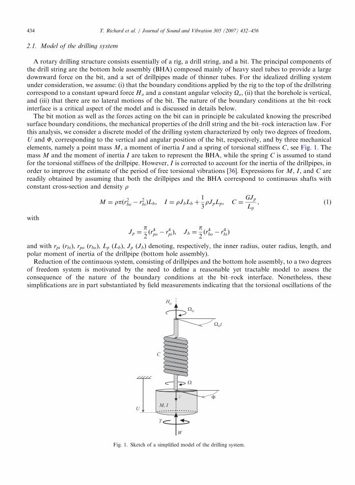
2.1. Model of the drilling system
A rotary drilling structure consists essentially of a rig, a drill string, and a bit. The principal components ofthe drill string are the bottom hole assembly (BHA) composed mainly of heavy steel tubes to provide a largedownward force on the bit, and a set of drillpipes made of thinner tubes. For the idealized drilling systemunder consideration, we assume: (i) that the boundary conditions applied by the rig to the top of the drillstringcorrespond to a constant upward force Ho and a constant angular velocity Oo, (ii) that the borehole is vertical,and (iii) that there are no lateral motions of the bit. The nature of the boundary conditions at the bit–rockinterface is a critical aspect of the model and is discussed in details below.
The bit motion as well as the forces acting on the bit can in principle be calculated knowing the prescribedsurface boundary conditions, the mechanical properties of the drill string and the bit–rock interaction law. Forthis analysis, we consider a discrete model of the drilling system characterized by only two degrees of freedom,U and F, corresponding to the vertical and angular position of the bit, respectively, and by three mechanicalelements, namely a point mass M, a moment of inertia I and a spring of torsional stiffness C, see Fig. 1. Themass M and the moment of inertia I are taken to represent the BHA, while the spring C is assumed to standfor the torsional stiffness of the drillpipe. However, I is corrected to account for the inertia of the drillpipes, inorder to improve the estimate of the period of free torsional vibrations [36]. Expressions for M, I , and C arereadily obtained by assuming that both the drillpipes and the BHA correspond to continuous shafts withconstant cross-section and density r
M ¼ rpðr2bo � r2biÞLb; I ¼ rJbLb þ1
3rJpLp; C ¼
GJp
Lp
, (1)
with
Jp ¼p2ðr4po � r4piÞ; Jb ¼
p2ðr4bo � r4biÞ
and with rpi (rbi), rpo (rbo), Lp (Lb), Jp (Jb) denoting, respectively, the inner radius, outer radius, length, andpolar moment of inertia of the drillpipe (bottom hole assembly).
Reduction of the continuous system, consisting of drillpipes and the bottom hole assembly, to a two degreesof freedom system is motivated by the need to define a reasonable yet tractable model to assess theconsequence of the nature of the boundary conditions at the bit–rock interface. Nonetheless, thesesimplifications are in part substantiated by field measurements indicating that the torsional oscillations of the
Fig. 1. Sketch of a simplified model of the drilling system.
ARTICLE IN PRESST. Richard et al. / Journal of Sound and Vibration 305 (2007) 432–456 435
drill bit are dominated by the first mode of vibrations of the drilling system. In fact, these field observationshave often justified the reduction of the drilling system to a torsional pendulum [37]. We have also chosen toneglect any damping of the system as most of the energy dissipation in drilling systems is taking place at thebit–rock interface; this dissipation is accounted for by the bit–rock interaction laws discussed below.
The asymmetry in the axial and torsional description of the reduced system stems from the different natureof the two boundary conditions at the rig: ‘‘fixed’’ in rotation (i.e., imposed angular position Oot), and ‘‘free’’in translation (i.e., imposed constant axial force Ho). These boundary conditions at the top of the drill stringimply that the axial stiffness of the pipes can be disregarded in this particular discrete model. Despiteneglecting the axial stiffness, non-trivial axial motions of the bit arise from the coupling between the twovibration modes through the bit–rock interaction.
Given the constant angular velocity Oo and constant upward tension Ho imposed to the upper end of thetorsional spring, we seek to determine the unknown bit response RðtÞ ¼ fW ðtÞ;V ðtÞ;TðtÞ;OðtÞg. This response,which is generally a function of time t, consists of two sets of conjugated dynamical and kinematicalquantities: the weight-on-bit W and the vertical bit velocity V ¼ dU=dt (also called rate of penetration) on theone hand, and the torque-on-bit T and the angular bit velocity O ¼ dF=dt on the other hand. (Refer to Fig. 1for the sign convention adopted for these quantities.)
2.2. Bit– rock interface
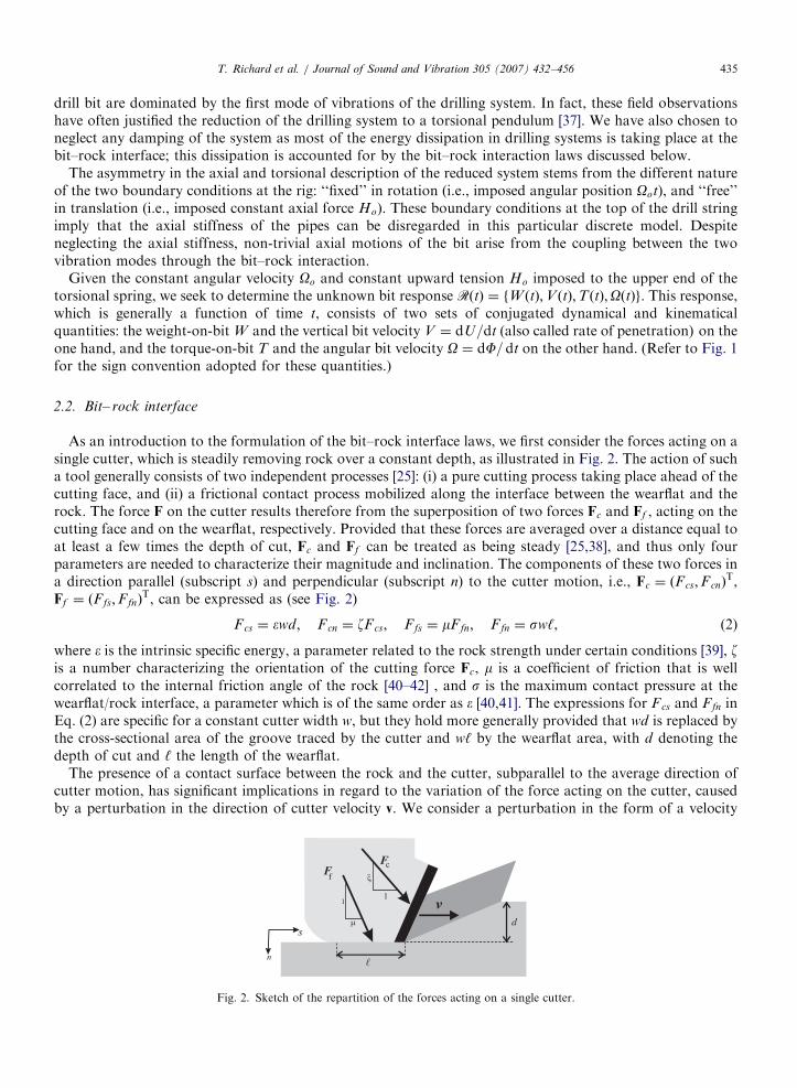
As an introduction to the formulation of the bit–rock interface laws, we first consider the forces acting on asingle cutter, which is steadily removing rock over a constant depth, as illustrated in Fig. 2. The action of sucha tool generally consists of two independent processes [25]: (i) a pure cutting process taking place ahead of thecutting face, and (ii) a frictional contact process mobilized along the interface between the wearflat and therock. The force F on the cutter results therefore from the superposition of two forces Fc and Ff , acting on thecutting face and on the wearflat, respectively. Provided that these forces are averaged over a distance equal toat least a few times the depth of cut, Fc and Ff can be treated as being steady [25,38], and thus only fourparameters are needed to characterize their magnitude and inclination. The components of these two forces ina direction parallel (subscript s) and perpendicular (subscript n) to the cutter motion, i.e., Fc ¼ ðF cs;FcnÞ
T,Ff ¼ ðFfs;FfnÞ
T, can be expressed as (see Fig. 2)
Fcs ¼ �wd; F cn ¼ zF cs; F fs ¼ mF fn; F fn ¼ sw‘, (2)
where � is the intrinsic specific energy, a parameter related to the rock strength under certain conditions [39], zis a number characterizing the orientation of the cutting force Fc, m is a coefficient of friction that is wellcorrelated to the internal friction angle of the rock [40–42] , and s is the maximum contact pressure at thewearflat/rock interface, a parameter which is of the same order as � [40,41]. The expressions for Fcs and Ffn inEq. (2) are specific for a constant cutter width w, but they hold more generally provided that wd is replaced bythe cross-sectional area of the groove traced by the cutter and w‘ by the wearflat area, with d denoting thedepth of cut and ‘ the length of the wearflat.
The presence of a contact surface between the rock and the cutter, subparallel to the average direction ofcutter motion, has significant implications in regard to the variation of the force acting on the cutter, causedby a perturbation in the direction of cutter velocity v. We consider a perturbation in the form of a velocity
Fig. 2. Sketch of the repartition of the forces acting on a single cutter.
ARTICLE IN PRESST. Richard et al. / Journal of Sound and Vibration 305 (2007) 432–456436
component vn (small compared to vs) which is superimposed on the initial velocity vs. If vno0 (leading to adecreasing depth of cut), there is a momentary loss of contact at the wearflat interface that is associated with adiscontinuous force response as F becomes suddenly equal to Fc. If vn40, the force on the cutter will increasemonotonically in view of the dependence of the magnitude of the cutting force on the depth of cut (with theforce Ff remaining virtually unchanged). We will also interpret the expression for Ffn in Eq. (2) to imply thatthe cutter is only in frictional contact with the rock (i.e. d ¼ 0) if Fnosw‘. In reality, some cutting is takingplace when Fnosw‘ but how much rock is removed depends on how the wearflat is in conforming contactwith the rock.
These concepts can be extended to model the generalized forces acting on a drill bit by integrating the effectsof all the individual cutters [25]. The torque T and weight-on-bit W can also be decomposed into acontribution associated to the forces transmitted by the cutting face of each cutter (denoted by the subscript c)and another corresponding to the forces acting on the cutter wearflats (denoted by the subscript f )
T ¼ Tc þ Tf ; W ¼W c þW f . (3)
The cutting components of the torque Tc and weight W c can be written as
Tc ¼12� a2d; W c ¼ z� a d, (4)
while the torque Tf and weight-on-bit W f are related according to
2Tf ¼ magW f . (5)
In the above equations, a denotes the bit radius and g is a bit geometry number (greater than 1) thatcharacterizes the orientation and spatial distribution of the frictional contact surfaces associated with thecutters.
The expressions in Eq. (4) for Tc and W c, which echo the expressions in Eq. (2) for the forces Fcs and Fcn ona single cutter, are assumed to be valid at any moment as the averaging of the forces fluctuations on all thecutters of the bit has the same effect as the averaging over distance implied for a single cutter.
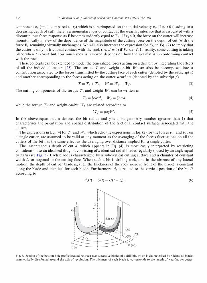
The instantaneous depth of cut d, which appears in Eq. (4), is most easily interpreted by restrictingconsideration to an idealized drag bit consisting of n identical radial blades regularly spaced by an angle equalto 2p=n (see Fig. 3). Each blade is characterized by a sub-vertical cutting surface and a chamfer of constantwidth ‘n orthogonal to the cutting face. When such a bit is drilling rock, and in the absence of any lateralmotion, the depth of cut per blade dn (i.e., the thickness of the rock ridge in front of the blade) is constantalong the blade and identical for each blade. Furthermore, dn is related to the vertical position of the bit U
according to
dnðtÞ ¼ UðtÞ �Uðt� tnÞ, (6)
Fig. 3. Section of the bottom-hole profile located between two successive blades of a drill bit, which is characterised by n identical blades
symmetrically distributed around the axis of revolution. The thickness of each blade ‘n corresponds to the length of wearflat per cutter.
ARTICLE IN PRESST. Richard et al. / Journal of Sound and Vibration 305 (2007) 432–456 437
where tn ðtÞ is the time required for the bit to rotate by an angle 2p=n to its current position at time t, asschematically illustrated in Fig. 3. The delay tnðtÞ is solution of
FðtÞ � Fðt� tnÞ ¼ 2p=n. (7)
The equivalent wearflat length for the bit is ‘ ¼ n‘n and the combined depth of cut of the bit is simply d ¼ ndn
or
d ¼ n½UðtÞ �Uðt� tnÞ�. (8)
The depth of cut d appearing in Eq. (4) also represents the depth of cut per revolution of the bit, i.e.,d ¼ 2pV=O, under steady conditions or when it is averaged over several revolutions.
The additional relationship needed to resolve the depth of cut d corresponding to a prescribed W dependson the direction of the instantaneous axial bit velocity, which impacts on W f as discussed below. Irrespectiveof the magnitude of W f and Tf , however, a constraint on the bit response can be deduced by combiningEqs. (3)–(5) to yield
2T
a2¼ ð1� bÞ�d þ mg
W
a, (9)
with
b ¼ mgz. (10)
The linear constraint given in Eq. (9) applies as long as the bit is drilling.The interaction between the bit and the rock can be classified into the following four modes:
�
Cutting (O40; d40). Consider first the ‘‘normal case’’ when V40. The cutting and frictional componentsof W and T are explicitly given by Eq. (4) andW f ¼ a‘s; Tf ¼a2
2gm‘s, (11)
where the average contact pressure s is assumed to be constant when V40 and O40 and the bit is cutting(d40). Thus drilling occurs in the normal case, only if W4W f and T4Tf . Consider next the case Vo0and O40 when the bit is moving upwards. We assume a complete loss of contact between the wearflat andthe rock, so that the frictional components W f and Tf vanish. Hence W ¼W c and T ¼ Tc, as long asd40. When V ¼ 0 , W f ¼W o �W c.
� Sticking (O ¼ 0; d40). During the stick phase the bit remains immobile. In this case, d represents the‘‘step’’ in front of the blades that dictates the minimum forces (W ; T) to be applied in order to exit the stickmode. During this phase, V ¼ 0, U ¼ UðtkÞ and F ¼ FðtkÞ with tk denoting the time at which the bit sticks.We assume complete contact between the wearflat (or chamfer) and the rock during the sticking phase.
� Sliding (O40; d ¼ 0). In sliding mode, the rate of penetration V and the cutting components of the forces(Tc;W c) vanish.
� Off-bottom (O40; do0). The bit is not in contact with the hole bottom and thus T ¼W ¼ 0. Such acomplete loss of contact between the bit and the rock takes place during bit bouncing.
2.3. Governing equations
The non-trivial bit response RðtÞ ¼ fW ðtÞ;V ðtÞ;TðtÞ;OðtÞg can, in principle, be determined from the surfaceconditions and the bit–rock interface laws, together with the following torsional and axial equations ofmotion:
Id2Fdt2þ CðF� FoÞ ¼ To � Tðt0F;
t0UÞ,
Md2U
dt2¼W o �W ðt0F;
t0UÞ, ð12Þ
ARTICLE IN PRESST. Richard et al. / Journal of Sound and Vibration 305 (2007) 432–456438
where Fo, To, and W o are the stationary quantities associated with the trivial solution, see Eqs. (15) and (18).In view of the nature of the interaction laws discussed above, both T and W are actually functions of thehistory of F (denoted by t
0F) and the history of U (denoted by t0U). Indeed the cutting components of T and
W are proportional to the depth of cut d, a state variable that is defined by comparing the current bit positionUðtÞ to a previous position Uðt� tnÞ in accordance with Eq. (8), with the delay tn solution of Eq. (7). Thesystem of equations in Eq. (12) represent a retarded dynamical system [43]. Furthermore, this system ischaracterized by a state-dependent delay [44], unlike similar systems that arise from the modeling of variousmetal machining processes for which the delay can be assumed to be constant [27,29].
An additional complexity of the model arises from the discontinuous nature of the boundary conditionsduring stick–slip. For the sake of simplicity, we assume that the frictional component of the torque is sufficientto hinder any backward rotation of the bit. Therefore, the condition for the bit to stick at time tk is
dFdt¼ 0 at t ¼ tk. (13)
During the stick phase, rotation of the drill pipes continues at the surface, the torque applied by the drill pipesupon the bottom hole assembly, T ¼ CðF� OotÞ, builds up until its magnitude is sufficient to overcome thetorque (Tc þ Tf ) necessary to cut the rock. Thus the bit slips at time tp, given by the solution of
CðOotp � FkÞ ¼a2
2ð�dk þ mg‘sÞ, (14)
where Fk ¼ FðtkÞ and dk ¼ dðtkÞ.
2.4. Steady-state solution
There is a steady-state (trivial) response of the bit, Ro ¼ fW o;V o;To; Oog, which is characterized by
W o ¼W s �Ho; O ¼ Oo; Fo ¼ Oo t� To=C, (15)
where W s is the submerged weight of the drill string. Steady-state drilling conditions represent particularinstances of the normal case (V40, O40). The delay tno is here constant and given by
tno ¼2p
nOo
(16)
and thus the depth of cut is
do ¼2pVo
Oo
. (17)
The penetration rate V o and torque-on-bit To are readily deduced from the bit–rock interaction laws given inEqs. (3) and (4), thus
V o ¼ðW o �W f ÞOo
2paz�; To ¼ Tf þ
aðW o �W f Þ
2zif W o4W f . (18)
The bit is not drilling if W opW f , i.e., V o ¼ 0 and To ¼ a g mW o=2. Hence the steady-state solution is fullydefined by the bit–rock interface and the control parameters, as it is not affected by the inertia and stiffness ofthe drilling system.
3. Scaling
We show now that the 13 physical parameters controlling the dynamical system can be reduced, by scaling,to 6 dimensionless quantities. The dimensionless formulation hinges on introducing a time scale that reflectsthe global response of the drilling structure and a length scale that embodies the interaction between the bitand the rock. The time scale is proportional to the period of the first resonant mode of torsional oscillationswhile the length scale is a characteristic depth of cut. These two scales echo the multiscale nature of this
ARTICLE IN PRESST. Richard et al. / Journal of Sound and Vibration 305 (2007) 432–456 439
problem, namely that vibrations of a structure with characteristic length of order of 103 m are triggered bycutting processes at the bit–rock interface that are characterized by depths of cut of order of 10�3 m.
3.1. Dimensionless formulation
To formulate the model in dimensionless form, we first need to introduce a time scale t� and a characteristiclength L� which are defined by
t� ¼
ffiffiffiffiI
C
r; L� ¼
2C
� a2. (19)
While 2p t� is the period of the resonant torsional vibration of the discrete drilling system, L� represents thedepth of cut when drilling with a perfectly sharp bit (‘ ¼ 0) subjected to a torque that induces a twist of1 radian in the drill string (typically, t��1 s and L��1mm). The scaled kinematical and dynamical quantities atthe bit, i.e. u, v, j, o, W, T, are then defined as
u ¼U �Uo
L�; v ¼
V t�
L�; j ¼ F� Fo; o ¼ O t�; W ¼
W
z�aL�; T ¼
T
C, (20)
where Uo ¼ Vo t is the vertical bit position according to the trivial response. Thus, u and j representperturbations of the axial and angular positions of the bit with respect to the trivial motion. We also define thedimensionless depth of cut d:
d ¼d
L�. (21)
All these quantities are function of the scaled time t:
t ¼t
t�. (22)
Note that v ¼ vo þ _u and o ¼ oo þ _j, with the dot denoting differentiation with respect to t and vo and oo
representing the trivial dimensionless rate of penetration and bit angular velocity, respectively.The scaled bit response BðtÞ ¼ fW, v, T, og depends on two classes of parameters: on the one hand the
control parameters corresponding to the prescribed weight-on-bit and rotation speed
Wo ¼W o
z �aL�; oo ¼ Oot�, (23)
and on the other hand the model parameters, i.e., the number of blades n and the lumped parameterscharacterizing the bit geometry, its wear state, and the drilling structure:
n; b ¼ mgz; l ¼s‘z�L�
; c ¼z�aI
MC. (24)
The typical range of variation of both control parameters is ½1; 10�. The bluntness number l and the bit–rockinteraction number b are of order 1. The system number c is the only large number of this problem as it is oforder 102–103; its largeness confirms that inertia of the bottom hole assembly cannot be neglected. Note thatthe dimensionless formulation has reduced the number of parameters from 13 (M ; I ;C; �; m;s; z; a; g;‘; n;W o;Oo) to 6 (n; l;b;c;Wo;oo).
3.2. Scaled mathematical model
The non-trivial response BðtÞ is governed by the conditions at the surface and at the bit–rock interface andby the momentum balance equations (Eq. (12)), which can be written in dimensionless form as
€u ¼ cðWo �WÞ; €jþ j ¼To �T. (25)
Recall that both T and W are functionals of the history of j (denoted by t0j) and u (denoted by t
0u).
ARTICLE IN PRESST. Richard et al. / Journal of Sound and Vibration 305 (2007) 432–456440
The bit–rock interaction laws are functions of the combined depth of cut d for the bit. We choose to expressd in terms of a perturbation d from the depth of cut per revolution for the trivial motion, do ¼ 2pvo=oo
d ¼ do þ d. (26)
The perturbation d is given by
d ¼ nvotn þ nðu� ~uÞ, (27)
where ~uðtÞ ¼ uðt� tnÞ is the delayed motion, and tn ¼ tn � tno with tnðtÞ the actual delay and tno ¼ 2p=noo
the constant delay for the trivial response. The algebraic equation governing the delay perturbation tnðtÞ isdeduced from Eq. (7) and the above definitions to be
ootn þ j� ~j ¼ 0, (28)
with ~jðtÞ ¼ j t� tnð Þ.The bit–rock interaction laws can be summarized as follows. If _j4� oo,
W�Wo ¼ dþWf � l, ð29Þ
T�To ¼ dþ bðWf � lÞ, ð30Þ
where
Wf ¼l if _u4� vo;
0 if _uo� vo:
((31)
If _u ¼ �vo then 0oWf ol and Wf is deduced from the balance of linear momentum.The bit stick at time tk when
_j ¼ �oo at t ¼ tk (32)
and then slips at time tp given by
tp ¼ tk þ ½jðtkÞ þTðtkÞ �To�=oo. (33)
It is interesting to note that the prescribed rotation speed oo of the drill string enters the governingequations via the delay function tn tð Þ, as a consequence of the nature of the bit–rock interface.
The system of equations that has to be solved for BðtÞ is unusual, in view of the delayed nature of thedifferential equations (with an a priori unknown delay) and their coupling through the variable d, as well asthe existence of two discontinuities (the loss of frictional contact and the stick phase). In the absence ofvibrations, the response BðtÞ is simply the trivial solution Bo ¼ fWo; vo, To, oog, with vo and To given by
vo ¼oo
2pðWo � lÞ; To ¼Wo þ lðb� 1Þ, (34)
if cutting is taking place (Wo4l).The numerical procedure used to solve the system of Eqs. (25)–(33) is discussed in Appendix C.
4. Self-excited vibrations
In this section, we demonstrate that the nonlinear dynamical system is prone to self-excited vibrations. First,we conduct a linear stability analysis that indicates that the trivial motion is unstable. This analysis is carriedout on the assumption that c is large enough to permit approximating the state-dependent delay system as aconstant delay system for which the stability conditions are known. Next we summarize the results ofnumerical simulations showing that the nonlinear system usually evolves towards a limit (or a quasi-limit)cycle. In particular, the existence of a limit cycle with stick–slip oscillations appears to be associated with bo1.
ARTICLE IN PRESST. Richard et al. / Journal of Sound and Vibration 305 (2007) 432–456 441
4.1. Linear stability analysis
As a prelude to the numerical simulations, we investigate the evolution of small perturbations to the trivialsolution in order to assess the self-excited nature of the system of equations. There are, however, hardly anypublished results regarding the stability of state-dependent delay system that could guide our analysis.Therefore, we first develop an argument based on the separation of time scales between the axial and torsionalvibrations to justify the transformation of the dynamical system into a simplified constant delay system, forwhich the stability criterion is known. Furthermore, to avoid having to deal with discontinuities in theboundary conditions, the stability analysis is conducted on the assumption that the disturbances are smallenough to ensure a permanent frictional contact between the bit and the rock (Wf ¼ l).
The linearized equations governing the evolution of the perturbations are deduced from Eqs. (25), (29) and(30) to be
€u ¼ �nc �vo
oo
j� �jð Þ þ u� �u
� �, (35)
€jþ j ¼ �n �vo
oo
j� �jð Þ þ u� �u
� �, (36)
where �u ¼ uðt� tnoÞ and �j ¼ jðt� tnoÞ, thus corresponding to a constant delay (tn ¼ 0). Analysis of thestability of the equilibrium points, where u is constant (implying u ¼ �u) and j ¼ 0, of the above two equationshinges on the recognition that there is essentially a time separation between the axial and torsional dynamics inview of the largeness of c. Indeed, the axial perturbations u evolve relative to a time scale, which is c1=2
smaller than the reference time scale for the torsional perturbations j, as can be noted by eliminating c fromEq. (35) through the introduction of a stretched time t0 ¼ c1=2t.
One consequence of this temporal disconnection is that the term ðj� �jÞ in the axial equation, Eq. (35), canbe treated as fixed. Furthermore, the torsional perturbations are virtually non-existent in the time boundarylayer (in terms of t0) where the axial perturbations might possibly grow. Hence, the stability of the equilibriumpoint u ¼ const. can be assessed from the uncoupled equation [45]
€uþ ncu� nc �u ¼ 0, (37)
where Eq. (37) has been written in terms of the original time t, and thus applies over t ¼ Oðc�1=2Þ.The stability of the equilibrium point u ¼ 0 can be assessed from general results obtained for the second-
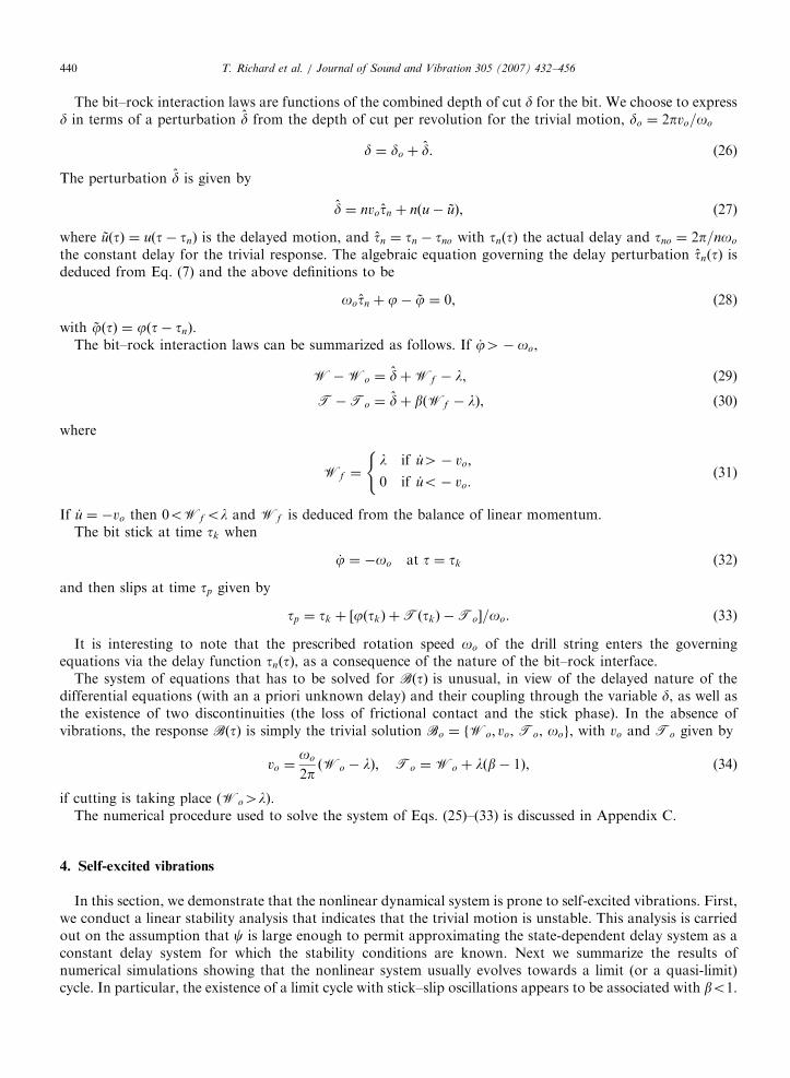
order delay differential equation [46,47]
d2
dx2xðxÞ þ qxðxÞ þ rxðx� 1Þ ¼ 0. (38)
The trivial solution x ¼ 0 of Eq. (38) is stable provided that the parameters r and q are within regions boundedby the linear segments
r ¼ 0; r ¼ ð�1Þk½q� ðk � 1Þ2p2�; k ¼ 1; 2; . . . (39)
as depicted in Fig. 4. Because q ¼ �r in the linearized delay equation governing the evolution of axialperturbations, the trivial solution u ¼ 0 is in fact never asymptotically stable. However, u ¼ 0 can still bestable in the Lyapunov sense (i.e., the solution neither diverges, nor converges) or unstable. The stability of theequilibrium point u ¼ const. (equivalent to _u ¼ 0) is investigated in Appendix B, where it is shown that theequilibrium point _u ¼ 0 is asymptotically stable when tnootnc, marginally stable when tno ¼ tnc and unstablewhen tno4 tnc, with the critical delay tnc ¼ p=
ffiffiffiffiffiffiffiffiffi2nc
p.
If the equilibrium point _u ¼ 0 is stable, the right-hand side of Eq. (35) vanishes for large t0; with theimplication that Eq. (36) simplifies at t ¼ Oð1Þ as
€jþ j ¼ 0. (40)
This indicates that the torsional motion is stable if the axial motion is stable and thus suggests that axialinstability is a precursor of the torsional instability.
ARTICLE IN PRESS
Fig. 4. Complete stability charts in the parametric space, after Refs. [47,48].
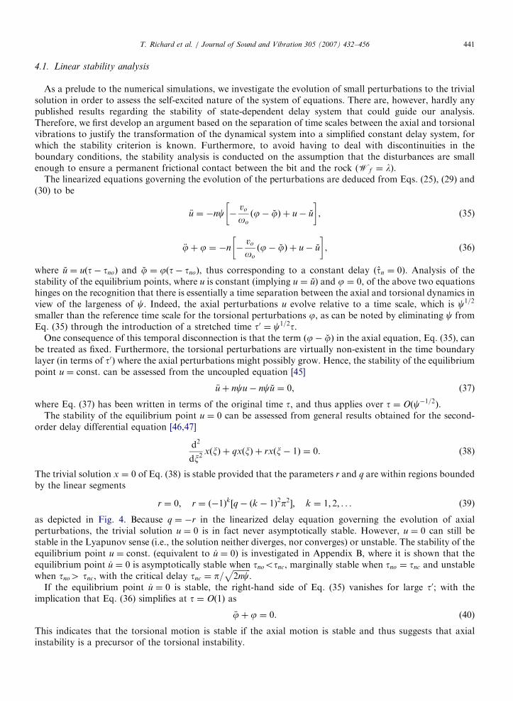
Fig. 5. Phase diagram (n ¼ 6; c ¼ 50; b ¼ 0:3; oo ¼ 5; Wo ¼ 7; l ¼ 5).
T. Richard et al. / Journal of Sound and Vibration 305 (2007) 432–456442
4.2. Limit cycles
Extensive numerical simulations confirm that the system naturally experiences self-excited vibrations, as anyperturbations to the trivial motion (even of numerical nature) cause the system to evolve towards one regimeof self-excited axial and torsional vibrations. For sets of parameters representative of field values, the solutionof the system evolves usually towards a periodic motion characterized either by a strict limit cycle (see Fig. 5)or by a quasi-limit cycle that evolves very slowly compared to the characteristic time of the system. Differentregimes of vibrations such as stick–slip oscillations or bit bouncing are observed under different conditions.
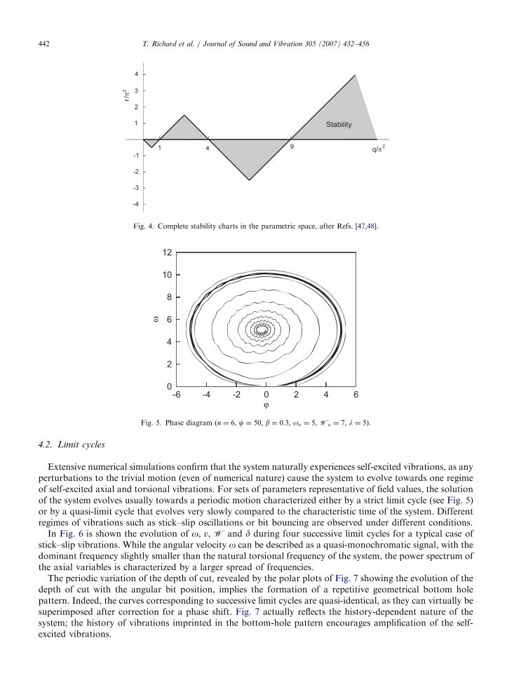
In Fig. 6 is shown the evolution of o; v, W and d during four successive limit cycles for a typical case ofstick–slip vibrations. While the angular velocity o can be described as a quasi-monochromatic signal, with thedominant frequency slightly smaller than the natural torsional frequency of the system, the power spectrum ofthe axial variables is characterized by a larger spread of frequencies.
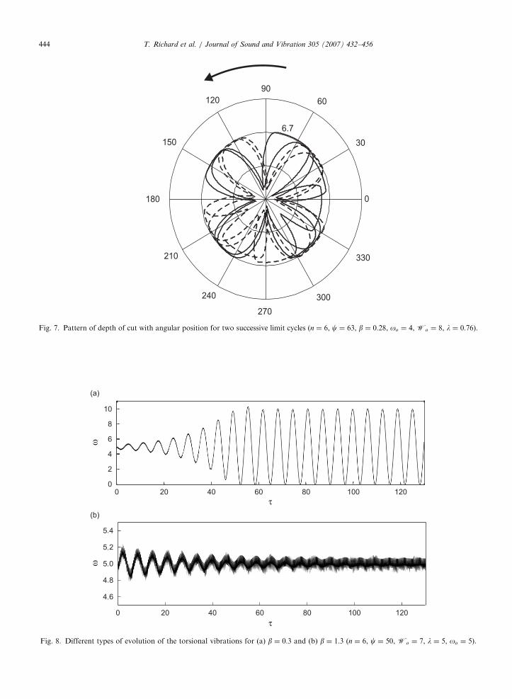
The periodic variation of the depth of cut, revealed by the polar plots of Fig. 7 showing the evolution of thedepth of cut with the angular bit position, implies the formation of a repetitive geometrical bottom holepattern. Indeed, the curves corresponding to successive limit cycles are quasi-identical, as they can virtually besuperimposed after correction for a phase shift. Fig. 7 actually reflects the history-dependent nature of thesystem; the history of vibrations imprinted in the bottom-hole pattern encourages amplification of the self-excited vibrations.
ARTICLE IN PRESS
ω
v
τ
τ
Fig. 6. Evolution with time t of (a) o and n, and (b) T and W (n ¼ 6, c ¼ 50, b ¼ 0:3, oo ¼ 5, Wo ¼ 7, l ¼ 5).
T. Richard et al. / Journal of Sound and Vibration 305 (2007) 432–456 443
4.3. Stick– slip vibrations
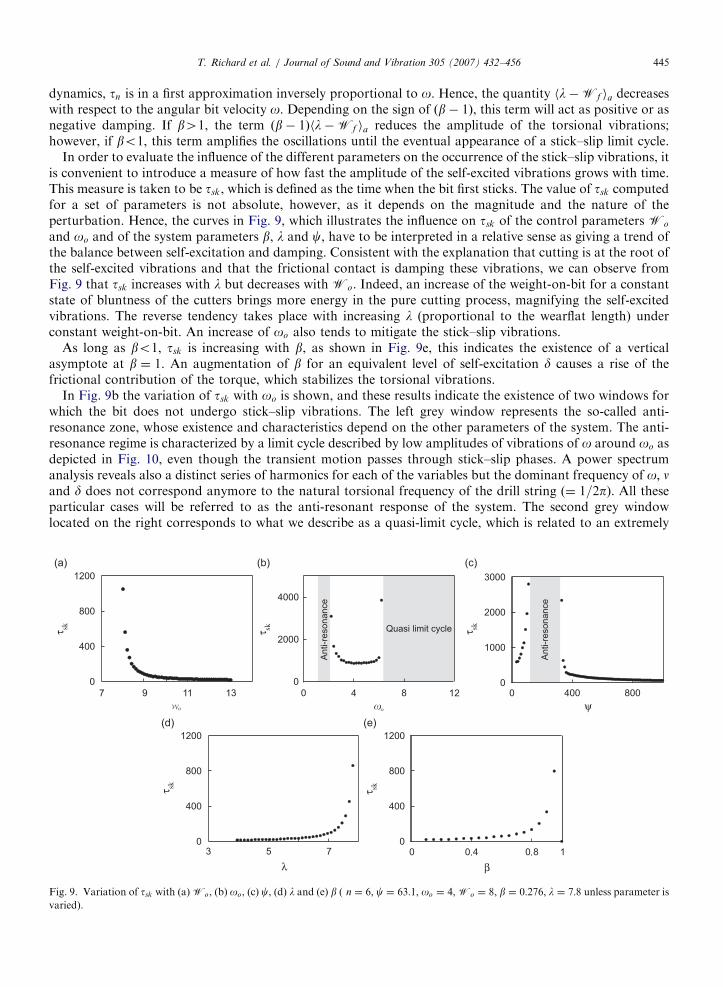
For typical values of the control and model parameters, b appears to be the only parameter of the modelthat can prohibit the occurrence of stick–slip oscillations, as all the other parameters only influence the timerequired to reach a steady regime of stick–slip vibrations, once the system departs the trivial solution. In fact,the threshold b ¼ 1 separates two regimes of vibrations: for bo1, the torsional oscillations grow until a limitcycle characterized by stick slip oscillations is eventually reached, while for b41 torsional oscillations remainbounded and the system reaches a limit cycle without stick–slip. This important result is illustrated in Fig. 8,which shows the evolution of the magnitude of the torsional vibrations for b ¼ 0:3 and 1.3, following aperturbation at t ¼ 0. The numerical simulations remain consistent, however, with the linear stability analysis,which indicates that the system experiences self-excited vibrations irrespective of the value of b.
The critical role played by b on the existence of stick–slip vibrations can be explained by considering thetime scale separation of the axial and torsional dynamics. Since the axial dynamics evolves approximately
ffiffiffiffic
p(typically Oð10Þ) faster than the torsional dynamics, only the slow variations of the fast axial variables affectsthe angular motion. Thus, provided that c is large enough, the balance of angular momentum can besimplified as
€jþ j ¼ ðb� 1Þhl�Wf ia þ1
ch €uia, (41)
with hia denoting an average over one axial limit cycle.Moreover, the ‘‘fast’’ axial dynamics can be decoupled from the torsional dynamics by treating the delay as
a fixed parameter over one (fast) axial limit cycle [48]. In fact, it can be shown that h €uia ¼ 0 for a fixed delayand that hl�Wf ia increases with tn considered as fixed during one axial periodic orbit [49]. In the slow
ARTICLE IN PRESS
Fig. 7. Pattern of depth of cut with angular position for two successive limit cycles (n ¼ 6, c ¼ 63, b ¼ 0:28, oo ¼ 4, Wo ¼ 8, l ¼ 0:76).
ω
τ
ω
τ
Fig. 8. Different types of evolution of the torsional vibrations for (a) b ¼ 0:3 and (b) b ¼ 1:3 (n ¼ 6, c ¼ 50, Wo ¼ 7, l ¼ 5, oo ¼ 5).
T. Richard et al. / Journal of Sound and Vibration 305 (2007) 432–456444
ARTICLE IN PRESST. Richard et al. / Journal of Sound and Vibration 305 (2007) 432–456 445
dynamics, tn is in a first approximation inversely proportional to o. Hence, the quantity hl�Wf ia decreaseswith respect to the angular bit velocity o. Depending on the sign of ðb� 1Þ, this term will act as positive or asnegative damping. If b41, the term ðb� 1Þhl�Wf ia reduces the amplitude of the torsional vibrations;however, if bo1, this term amplifies the oscillations until the eventual appearance of a stick–slip limit cycle.
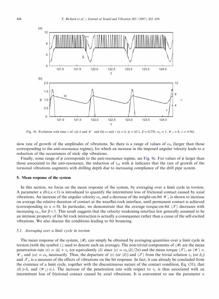
In order to evaluate the influence of the different parameters on the occurrence of the stick–slip vibrations, itis convenient to introduce a measure of how fast the amplitude of the self-excited vibrations grows with time.This measure is taken to be tsk, which is defined as the time when the bit first sticks. The value of tsk computedfor a set of parameters is not absolute, however, as it depends on the magnitude and the nature of theperturbation. Hence, the curves in Fig. 9, which illustrates the influence on tsk of the control parameters Wo
and oo and of the system parameters b, l and c, have to be interpreted in a relative sense as giving a trend ofthe balance between self-excitation and damping. Consistent with the explanation that cutting is at the root ofthe self-excited vibrations and that the frictional contact is damping these vibrations, we can observe fromFig. 9 that tsk increases with l but decreases with Wo. Indeed, an increase of the weight-on-bit for a constantstate of bluntness of the cutters brings more energy in the pure cutting process, magnifying the self-excitedvibrations. The reverse tendency takes place with increasing l (proportional to the wearflat length) underconstant weight-on-bit. An increase of oo also tends to mitigate the stick–slip vibrations.
As long as bo1, tsk is increasing with b, as shown in Fig. 9e, this indicates the existence of a verticalasymptote at b ¼ 1. An augmentation of b for an equivalent level of self-excitation d causes a rise of thefrictional contribution of the torque, which stabilizes the torsional vibrations.
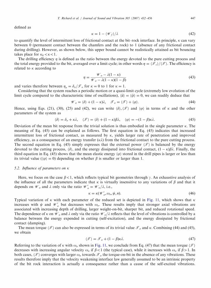
In Fig. 9b the variation of tsk with oo is shown, and these results indicate the existence of two windows forwhich the bit does not undergo stick–slip vibrations. The left grey window represents the so-called anti-resonance zone, whose existence and characteristics depend on the other parameters of the system. The anti-resonance regime is characterized by a limit cycle described by low amplitudes of vibrations of o around oo asdepicted in Fig. 10, even though the transient motion passes through stick–slip phases. A power spectrumanalysis reveals also a distinct series of harmonics for each of the variables but the dominant frequency of o; nand d does not correspond anymore to the natural torsional frequency of the drill string (¼ 1=2p). All theseparticular cases will be referred to as the anti-resonant response of the system. The second grey windowlocated on the right corresponds to what we describe as a quasi-limit cycle, which is related to an extremely
τ sk τ sk τ sk
τ skτ sk
ψ
βλ
Fig. 9. Variation of tsk with (a)Wo, (b) oo, (c) c, (d) l and (e) b ( n ¼ 6, c ¼ 63:1, oo ¼ 4,Wo ¼ 8, b ¼ 0:276, l ¼ 7:8 unless parameter is
varied).
ARTICLE IN PRESS
ω
v
ω
τ
v
δ
τ
Fig. 10. Evolution with time t of: (a) d and W and (b) o and n (n ¼ 6, c ¼ 63:1, b ¼ 0:276, oo ¼ 1, Wo ¼ 8, l ¼ 4:56).
T. Richard et al. / Journal of Sound and Vibration 305 (2007) 432–456446
slow rate of growth of the amplitudes of vibrations. So there is a range of values of oo (larger than thosecorresponding to the anti-resonance regime), for which an increase in the imposed angular velocity leads to areduction of the occurrences of stick–slip vibrations.
Finally, some range of c corresponds to the anti-resonance regime, see Fig. 9c. For values of c larger thanthose associated to the anti-resonance, the reduction of tsk with c indicates that the rate of growth of thetorsional vibrations augments with drilling depth due to increasing compliance of the drill pipe system.
5. Mean response of the system
In this section, we focus on the mean response of the system, by averaging over a limit cycle in torsion.A parameter k (0pko1) is introduced to quantify the intermittent loss of frictional contact caused by axialvibrations. An increase of the angular velocity oo and a decrease of the weight-on-bit Wo is shown to increaseon average the relative duration of contact at the wearflat/rock interface, until permanent contact is achieved(corresponding to k ¼ 0). In particular, we demonstrate that the average torque-on-bit hTi decreases withincreasing oo, for bo1. This result suggests that the velocity weakening interface law generally assumed to bean intrinsic property of the bit rock interaction is actually a consequence rather than a cause of the self-excitedvibrations. We also discuss the conditions leading to bit bouncing.
5.1. Averaging over a limit cycle in torsion
The mean response of the system, hBi, can simply be obtained by averaging quantities over a limit cycle intorsion (with the symbol h:i used to denote such an average). The non-trivial components of hBi are the meanpenetration rate hvi ¼ h _ui þ no (or equivalently hdi since hvi ¼ oohdi=2p) and the mean torque hTi, as hWi ¼Wo and hoi ¼ oo necessarily. Thus, the departure of hvi (or hdi) and hTi from the trivial solution no (or do)and To is a measure of the effects of vibrations on the bit response. In fact, it can already be concluded fromthe existence of a limit cycle, together with the discontinuous nature of the contact condition, Eq. (31), thathdiXdo and hWf ipl. The increase of the penetration rate with respect to no is thus associated with anintermittent loss of frictional contact caused by axial vibrations. It is convenient to use the parameter k
ARTICLE IN PRESST. Richard et al. / Journal of Sound and Vibration 305 (2007) 432–456 447
defined as
k ¼ 1� hWf i=l (42)
to quantify the level of intermittent loss of frictional contact at the bit–rock interface. In principle, k can varybetween 0 (permanent contact between the chamfers and the rock) to 1 (absence of any frictional contactduring drilling). However, as shown below, this upper bound cannot be realistically attained as bit bouncingtakes place for kkoko1.
The drilling efficiency Z is defined as the ratio between the energy devoted to the pure cutting process andthe total energy provided to the bit, averaged over a limit cycle; in other words Z ¼ hTci=hTi. The efficiency isrelated to k according to
Z ¼Wo � lð1� kÞ
Wo � lð1� kÞð1� bÞ(43)
and varies therefore between Zo ¼ do=To for k ¼ 0 to 1 for k ¼ 1.Considering that the system reaches a periodic motion or a quasi-limit cycle (extremely low evolution of the
limit cycle compared to the characteristic time of oscillations), h €ui ¼ h €ji ¼ 0, we can readily deduce that
Wo ¼ hdi þ ð1� kÞl; To ¼ hTi þ hji. (44)
Hence, using Eqs. (21), (30), (25) and (42), we can write hdi; hTi and hji in terms of k and the otherparameters of the system as
hdi ¼ do þ kl; hTi ¼ hdi þ ð1� kÞbl; hji ¼ �ð1� bÞkl. (45)
Deviation of the mean bit response from the trivial solution is thus embodied in the single parameter k. Themeaning of Eq. (45) can be explained as follows. The first equation in Eq. (45) indicates that increasedintermittent loss of frictional contact, as measured by k, yields larger rate of penetration and improvedefficiency, as a consequence of an energy transfer (kl) from the frictional contact to the pure cutting process.The second equation in Eq. (45) simply expresses that the external power hTi is balanced by the energydevoted to the cutting process, hdi, and the energy dissipated into frictional contact, ð1� kÞbl. Finally, thethird equation in Eq. (45) shows that the mean elastic energy hji stored in the drill pipes is larger or less thanits trivial value (hji ¼ 0) depending on whether b is smaller or larger than 1.
5.2. Influence of parameters on k
Here, we focus on the case bo1, which reflects typical bit geometries through g. An exhaustive analysis ofthe influence of all the parameters indicate that k is virtually insensitive to any variations of b and that itdepends on Wo and l only via the ratio W0
o ¼Wo=l, i.e.,
k ¼ kðW0o;oo;c; nÞ. (46)
Typical variation of k with each parameter of the reduced set is depicted in Fig. 11, which shows that kincreases with c and W0
o but decreases with oo. These results imply that stronger axial vibrations areassociated with increasing depth of drilling, larger weight-on-bit, sharper bit, and reduced rotational speed.The dependence of k onWo and l only via the ratioWo=l reflects that the level of vibrations is controlled by abalance between the energy expended in cutting (self-excitation), and the energy dissipated by frictionalcontact (damping).
The mean torque hTi can also be expressed in terms of its trivial value To and k. Combining (44) and (45),we obtain
hTi ¼To þ ð1� bÞkl. (47)
Referring to the variation of k with oo shown in Fig. 11, we conclude from Eq. (47) that the mean torque hTidecreases with increasing angular velocity oo if bo1 (the typical case), while it increases with oo if b41. Inboth cases, hTi converges with larger oo towardsTo the torque-on-bit in the absence of any vibrations. Theseresults therefore imply that the velocity weakening interface law generally assumed to be an intrinsic propertyof the bit rock interaction is actually a consequence rather than a cause of the self-excited vibrations.
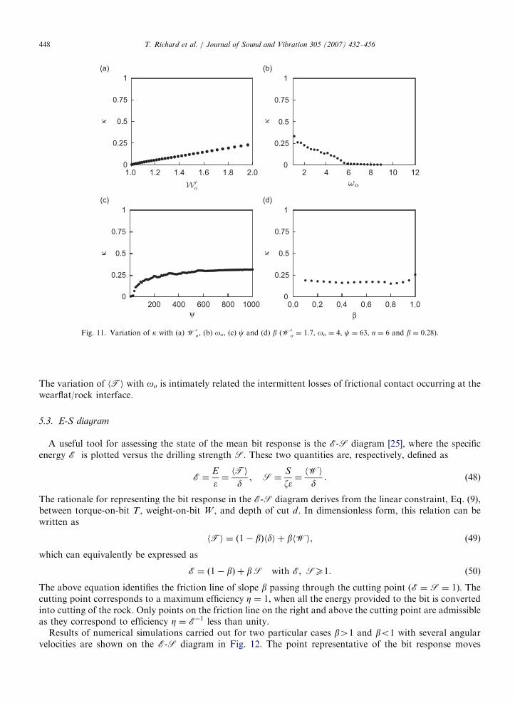
ARTICLE IN PRESS
0
0.25
0.5
0.75
1
0
0.25
0.5
0.75
1
0
0.25
0.5
0.75
1
0
0.25
0.5
0.75
1
κκ
κκ
ψ β
Fig. 11. Variation of k with (a) W0o, (b) oo, (c) c and (d) b (W0
o ¼ 1:7, oo ¼ 4, c ¼ 63, n ¼ 6 and b ¼ 0:28).
T. Richard et al. / Journal of Sound and Vibration 305 (2007) 432–456448
The variation of hTi with oo is intimately related the intermittent losses of frictional contact occurring at thewearflat/rock interface.
5.3. E-S diagram
A useful tool for assessing the state of the mean bit response is the E-S diagram [25], where the specificenergy E is plotted versus the drilling strength S. These two quantities are, respectively, defined as
E ¼E
�¼hTi
d; S ¼
S
z�¼hWi
d. (48)
The rationale for representing the bit response in the E-S diagram derives from the linear constraint, Eq. (9),between torque-on-bit T , weight-on-bit W , and depth of cut d. In dimensionless form, this relation can bewritten as
hTi ¼ ð1� bÞhdi þ bhWi, (49)
which can equivalently be expressed as
E ¼ ð1� bÞ þ bS with E; SX1. (50)
The above equation identifies the friction line of slope b passing through the cutting point (E ¼ S ¼ 1). Thecutting point corresponds to a maximum efficiency Z ¼ 1, when all the energy provided to the bit is convertedinto cutting of the rock. Only points on the friction line on the right and above the cutting point are admissibleas they correspond to efficiency Z ¼ E�1 less than unity.
Results of numerical simulations carried out for two particular cases b41 and bo1 with several angularvelocities are shown on the E-S diagram in Fig. 12. The point representative of the bit response moves
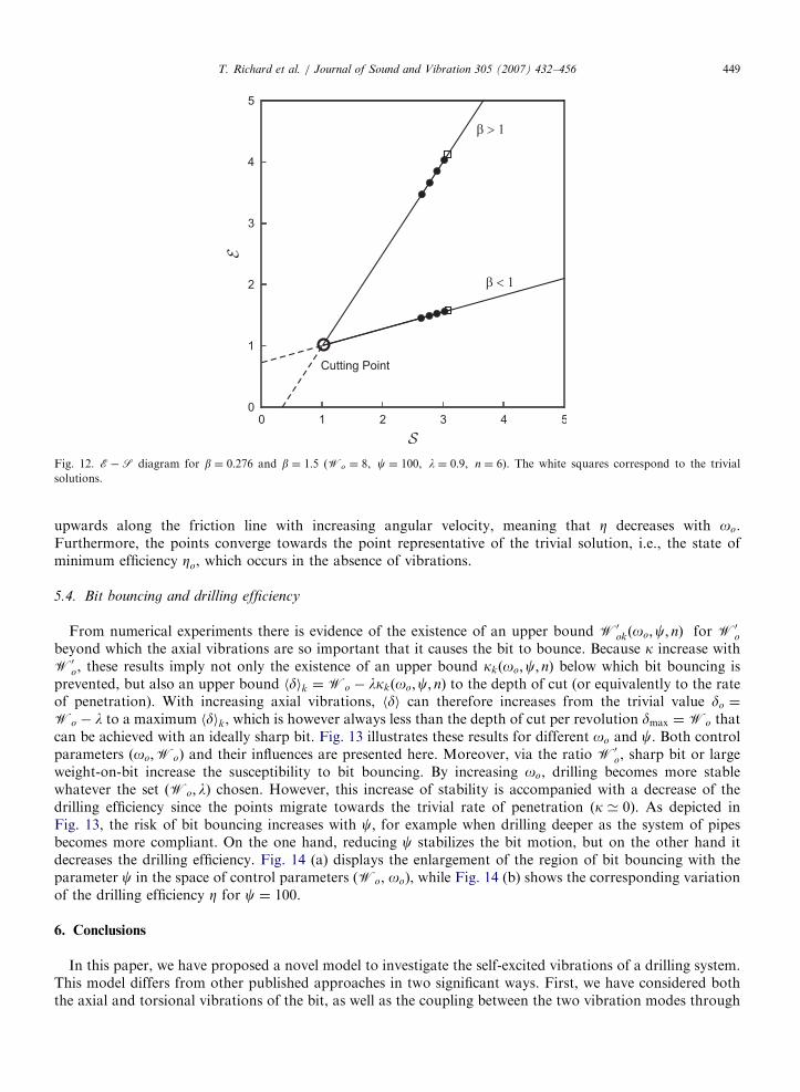
ARTICLE IN PRESS
Fig. 12. E�S diagram for b ¼ 0:276 and b ¼ 1:5 (Wo ¼ 8, c ¼ 100, l ¼ 0:9, n ¼ 6). The white squares correspond to the trivial
solutions.
T. Richard et al. / Journal of Sound and Vibration 305 (2007) 432–456 449
upwards along the friction line with increasing angular velocity, meaning that Z decreases with oo.Furthermore, the points converge towards the point representative of the trivial solution, i.e., the state ofminimum efficiency Zo, which occurs in the absence of vibrations.
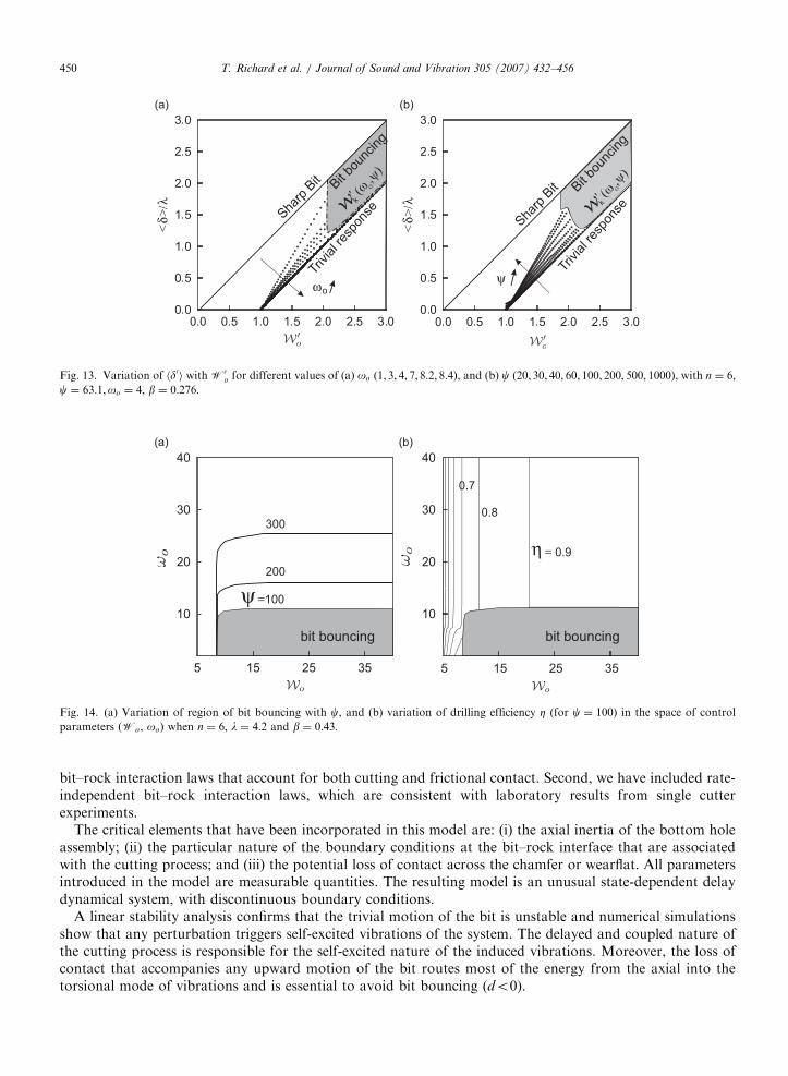
5.4. Bit bouncing and drilling efficiency
From numerical experiments there is evidence of the existence of an upper bound W0okðoo;c; nÞ for W0
o
beyond which the axial vibrations are so important that it causes the bit to bounce. Because k increase withW0
o, these results imply not only the existence of an upper bound kkðoo;c; nÞ below which bit bouncing isprevented, but also an upper bound hdik ¼Wo � lkkðoo;c; nÞ to the depth of cut (or equivalently to the rateof penetration). With increasing axial vibrations, hdi can therefore increases from the trivial value do ¼
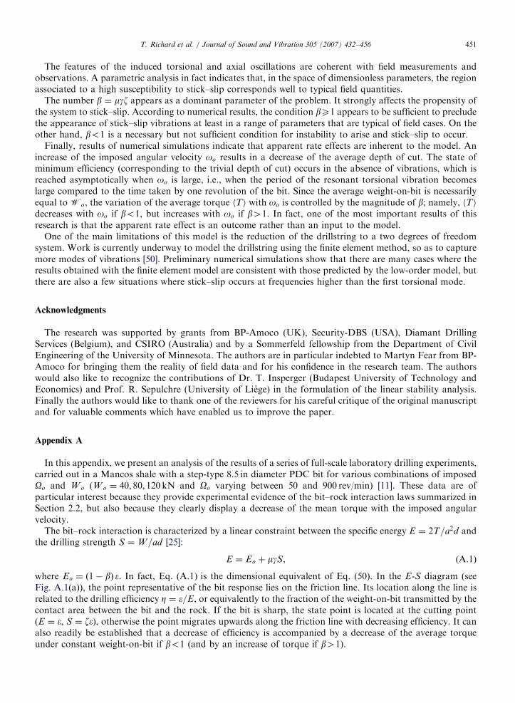
Wo � l to a maximum hdik, which is however always less than the depth of cut per revolution dmax ¼Wo thatcan be achieved with an ideally sharp bit. Fig. 13 illustrates these results for different oo and c. Both controlparameters ðoo;WoÞ and their influences are presented here. Moreover, via the ratio W0
o, sharp bit or largeweight-on-bit increase the susceptibility to bit bouncing. By increasing oo, drilling becomes more stablewhatever the set ðWo; lÞ chosen. However, this increase of stability is accompanied with a decrease of thedrilling efficiency since the points migrate towards the trivial rate of penetration (k ’ 0). As depicted inFig. 13, the risk of bit bouncing increases with c; for example when drilling deeper as the system of pipesbecomes more compliant. On the one hand, reducing c stabilizes the bit motion, but on the other hand itdecreases the drilling efficiency. Fig. 14 (a) displays the enlargement of the region of bit bouncing with theparameter c in the space of control parameters (Wo, oo), while Fig. 14 (b) shows the corresponding variationof the drilling efficiency Z for c ¼ 100.
6. Conclusions
In this paper, we have proposed a novel model to investigate the self-excited vibrations of a drilling system.This model differs from other published approaches in two significant ways. First, we have considered boththe axial and torsional vibrations of the bit, as well as the coupling between the two vibration modes through
ARTICLE IN PRESS
ψω
<δ>
/λ
<δ>
/λ
Fig. 13. Variation of hd0i with W0o for different values of (a) oo (1; 3; 4; 7; 8:2; 8:4), and (b) c (20; 30; 40; 60; 100; 200; 500; 1000), with n ¼ 6;
c ¼ 63:1;oo ¼ 4; b ¼ 0:276:
200
100
300
bit bouncing bit bouncing
0.9
0.8
0.7
ψ =
η =
Fig. 14. (a) Variation of region of bit bouncing with c, and (b) variation of drilling efficiency Z (for c ¼ 100) in the space of control
parameters (Wo, oo) when n ¼ 6; l ¼ 4:2 and b ¼ 0:43:
T. Richard et al. / Journal of Sound and Vibration 305 (2007) 432–456450
bit–rock interaction laws that account for both cutting and frictional contact. Second, we have included rate-independent bit–rock interaction laws, which are consistent with laboratory results from single cutterexperiments.
The critical elements that have been incorporated in this model are: (i) the axial inertia of the bottom holeassembly; (ii) the particular nature of the boundary conditions at the bit–rock interface that are associatedwith the cutting process; and (iii) the potential loss of contact across the chamfer or wearflat. All parametersintroduced in the model are measurable quantities. The resulting model is an unusual state-dependent delaydynamical system, with discontinuous boundary conditions.
A linear stability analysis confirms that the trivial motion of the bit is unstable and numerical simulationsshow that any perturbation triggers self-excited vibrations of the system. The delayed and coupled nature ofthe cutting process is responsible for the self-excited nature of the induced vibrations. Moreover, the loss ofcontact that accompanies any upward motion of the bit routes most of the energy from the axial into thetorsional mode of vibrations and is essential to avoid bit bouncing (do0).
ARTICLE IN PRESST. Richard et al. / Journal of Sound and Vibration 305 (2007) 432–456 451
The features of the induced torsional and axial oscillations are coherent with field measurements andobservations. A parametric analysis in fact indicates that, in the space of dimensionless parameters, the regionassociated to a high susceptibility to stick–slip corresponds well to typical field quantities.
The number b ¼ mgz appears as a dominant parameter of the problem. It strongly affects the propensity ofthe system to stick–slip. According to numerical results, the condition bX1 appears to be sufficient to precludethe appearance of stick–slip vibrations at least in a range of parameters that are typical of field cases. On theother hand, bo1 is a necessary but not sufficient condition for instability to arise and stick–slip to occur.
Finally, results of numerical simulations indicate that apparent rate effects are inherent to the model. Anincrease of the imposed angular velocity oo results in a decrease of the average depth of cut. The state ofminimum efficiency (corresponding to the trivial depth of cut) occurs in the absence of vibrations, which isreached asymptotically when oo is large, i.e., when the period of the resonant torsional vibration becomeslarge compared to the time taken by one revolution of the bit. Since the average weight-on-bit is necessarilyequal to Wo, the variation of the average torque hTi with oo is controlled by the magnitude of b; namely, hTidecreases with oo if bo1, but increases with oo if b41. In fact, one of the most important results of thisresearch is that the apparent rate effect is an outcome rather than an input to the model.
One of the main limitations of this model is the reduction of the drillstring to a two degrees of freedomsystem. Work is currently underway to model the drillstring using the finite element method, so as to capturemore modes of vibrations [50]. Preliminary numerical simulations show that there are many cases where theresults obtained with the finite element model are consistent with those predicted by the low-order model, butthere are also a few situations where stick–slip occurs at frequencies higher than the first torsional mode.
Acknowledgments
The research was supported by grants from BP-Amoco (UK), Security-DBS (USA), Diamant DrillingServices (Belgium), and CSIRO (Australia) and by a Sommerfeld fellowship from the Department of CivilEngineering of the University of Minnesota. The authors are in particular indebted to Martyn Fear from BP-Amoco for bringing them the reality of field data and for his confidence in the research team. The authorswould also like to recognize the contributions of Dr. T. Insperger (Budapest University of Technology andEconomics) and Prof. R. Sepulchre (University of Liege) in the formulation of the linear stability analysis.Finally the authors would like to thank one of the reviewers for his careful critique of the original manuscriptand for valuable comments which have enabled us to improve the paper.
Appendix A
In this appendix, we present an analysis of the results of a series of full-scale laboratory drilling experiments,carried out in a Mancos shale with a step-type 8.5 in diameter PDC bit for various combinations of imposedOo and W o (W o ¼ 40; 80; 120 kN and Oo varying between 50 and 900 rev/min) [11]. These data are ofparticular interest because they provide experimental evidence of the bit–rock interaction laws summarized inSection 2.2, but also because they clearly display a decrease of the mean torque with the imposed angularvelocity.
The bit–rock interaction is characterized by a linear constraint between the specific energy E ¼ 2T=a2d andthe drilling strength S ¼W=ad [25]:
E ¼ Eo þ mgS, (A.1)
where Eo ¼ ð1� bÞ �. In fact, Eq. (A.1) is the dimensional equivalent of Eq. (50). In the E-S diagram (seeFig. A.1(a)), the point representative of the bit response lies on the friction line. Its location along the line isrelated to the drilling efficiency Z ¼ �=E, or equivalently to the fraction of the weight-on-bit transmitted by thecontact area between the bit and the rock. If the bit is sharp, the state point is located at the cutting point(E ¼ �, S ¼ z�), otherwise the point migrates upwards along the friction line with decreasing efficiency. It canalso readily be established that a decrease of efficiency is accompanied by a decrease of the average torqueunder constant weight-on-bit if bo1 (and by an increase of torque if b41).
ARTICLE IN PRESST. Richard et al. / Journal of Sound and Vibration 305 (2007) 432–456452
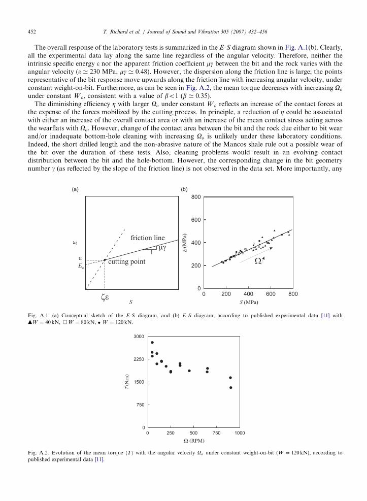
The overall response of the laboratory tests is summarized in the E-S diagram shown in Fig. A.1(b). Clearly,all the experimental data lay along the same line regardless of the angular velocity. Therefore, neither theintrinsic specific energy � nor the apparent friction coefficient mg between the bit and the rock varies with theangular velocity (� ’ 230 MPa, mg ’ 0:48). However, the dispersion along the friction line is large; the pointsrepresentative of the bit response move upwards along the friction line with increasing angular velocity, underconstant weight-on-bit. Furthermore, as can be seen in Fig. A.2, the mean torque decreases with increasing Oo
under constant W o, consistent with a value of bo1 (b ’ 0:35).The diminishing efficiency Z with larger Oo under constant W o reflects an increase of the contact forces at
the expense of the forces mobilized by the cutting process. In principle, a reduction of Z could be associatedwith either an increase of the overall contact area or with an increase of the mean contact stress acting acrossthe wearflats with Oo. However, change of the contact area between the bit and the rock due either to bit wearand/or inadequate bottom-hole cleaning with increasing Oo is unlikely under these laboratory conditions.Indeed, the short drilled length and the non-abrasive nature of the Mancos shale rule out a possible wear ofthe bit over the duration of these tests. Also, cleaning problems would result in an evolving contactdistribution between the bit and the hole-bottom. However, the corresponding change in the bit geometrynumber g (as reflected by the slope of the friction line) is not observed in the data set. More importantly, any
Fig. A.1. (a) Conceptual sketch of the E-S diagram, and (b) E-S diagram, according to published experimental data [11] with
mW ¼ 40 kN, &W ¼ 80 kN, � W ¼ 120kN.
Fig. A.2. Evolution of the mean torque hTi with the angular velocity Oo under constant weight-on-bit (W ¼ 120kN), according to
published experimental data [11].
ARTICLE IN PRESST. Richard et al. / Journal of Sound and Vibration 305 (2007) 432–456 453
variation of the torque due to inadequate removal of debris flow would happen over a time scale equivalent toseveral rotations, too large to be compatible with the time scale of the stick–slip oscillations.
The only remaining explanation is an increase of the mean contact stress s with Oo. Assuming permanentcontact between the bit flat and the rock, s would have to increase with the relative velocity between thewearflat and the rock. Although such a law cannot be ruled out a priori, no significant effect of the cuttingvelocity on the forces has been reported in the literature. However, the mean contact stress could increase withOo if axial vibrations responsible for an intermittent loss of contact between the bit and the rock progressivelydecrease in intensity with Oo. Such a result is actually predicted by the model discussed in the body of thispaper.
Interpretation of the laboratory drilling data [11] within the framework of the bit–rock interaction laws canbe summarized as follows: (i) the bit response is consistent with a bit–rock interaction model which takes intoaccount both the cutting and frictional processes mobilized at the bit–rock interface [25]; (ii) the rate effects arereal but they are not a constitutive property of the bit–rock interface, in the sense that they do not affect theparameters of the model (�, z, m, g); (iii) the rate effects are associated with an increase of the mean contactstress transmitted at the flat–rock interface with Oo.
Appendix B
In this appendix, we investigate the stability of the equilibrium point u ¼ Constant (equivalent to u ¼ �u) ofthe delay differential equation:
€uþ ncu� nc �u ¼ 0 (B.1)
governing the axial perturbation u. Consider the characteristic equation of Eq. (B.1)
PðsÞ ¼ s2 þ ncð1� e�stn Þ. (B.2)
The location of the roots of PðsÞ in the complex plane will determine the stability of _u ¼ 0. Because one root isalways located at the origin, we study instead the modified characteristic function
QðsÞ:¼PðsÞ
s¼ sþ
ncsð1� e�stnÞ. (B.3)
The equilibrium point _u ¼ 0 is asymptotically stable if and only if all the roots satisfying QðsÞ ¼ 0 arelocated on the left of the imaginary axis of the complex plane s. When tno ¼ 0, one root is located at the origin,and the solution _u ¼ 0 is thus stable in the Lyapunov sense.
When the equation becomes retarded (tno40), there exists an infinite number of roots. From Eq. (B.3) andbecause jð1� e�stn Þjo2 when Refsg40 and tno40, any roots with positive real part must lie within the half-circle centered on the origin of radius
ffiffiffiffiffiffiffiffiffi2nc
pðjsjo
ffiffiffiffiffiffiffiffiffi2nc
pÞ. Let us choose tno sufficiently small such that
1� e�stno � stno for any s satisfying jsjoffiffiffiffiffiffiffiffiffi2nc
p. The only root inside this circle is
so ¼ �nctno. (B.4)
Therefore, the root located at the origin for zero delay moves left for small tno:We can conclude that there isno root with positive real part for tno51 and that the equilibrium point _u ¼ 0 is asymptotically stable.
Next, let us study the root locus sðtnoÞ given by the implicit equation
s2 þ ncð1� e�stnoÞ ¼ 0. (B.5)
Although the solution _u ¼ 0 is asymptotically stable for small value of the delay, a bifurcation will occur if oneroot traverses the imaginary axis from left to right for larger tno. Let us compute the values of s ¼ iok; tno;k
such that
�o2k þ ncð1� e�ioktno;k Þ ¼ 0. (B.6)
The non-trivial solutions of Eq. (B.6) are given by
ok ¼ �ffiffiffiffiffiffiffiffiffi2nc
pwhen tno;k ¼
ð2k þ 1Þpffiffiffiffiffiffiffiffiffi2nc
p . (B.7)
ARTICLE IN PRESST. Richard et al. / Journal of Sound and Vibration 305 (2007) 432–456454
Moreover, the direction of travel of the roots with tno can be deduced from the derivative ds=dtno on the rootlocus PðsÞ ¼ 0, which can be deduced from
dPðsÞ
dtno
¼qP
qs
ds
dtno
þqP
qtno
¼ 0 (B.8)
and therefore,
ds
dtno
����P¼0
¼ �ncse�stn
2sþ nctne�stn. (B.9)
By looking at the real part of Eq. (B.9) at the crossing points s ¼ �iffiffiffiffiffiffiffiffiffi2nc
p, for tno ¼ ð2k þ 1Þp=
ffiffiffiffiffiffiffiffiffi2nc
p, we
obtain a strictly positive quantity
Reds
dtno
����PðsÞ¼0
( )¼
8nc
16þ ð2k þ 1Þ2p240. (B.10)
The two complex conjugate roots will pass from the left half-plane to the right half-plane at the first crossingtno;o ¼ p=
ffiffiffiffiffiffiffiffiffi2nc
pand will remain in the right half-plane. We can thus conclude that when tnoop=
ffiffiffiffiffiffiffiffiffi2nc
p, the
equilibrium point _u ¼ 0 and uðtÞ � uðt� tnoÞ ¼ 0 is asymptotically stable, marginally stable when tno ¼
p=ffiffiffiffiffiffiffiffiffi2nc
pand unstable when tno4p=
ffiffiffiffiffiffiffiffiffi2nc
p.
Appendix C
In this appendix the numerical procedure used to solve the nonlinear system described by Eqs. (25)–(33) isgiven. First, the two second-order differential equations (Eq. (25)) are reduced to four first-order differentialequations that are solved by using a simple Euler-forward finite difference technique. Although otheralgorithms have been implemented (such as second and fourth-order Runge–Kutta method), the Euleralgorithm was preferred because it is numerically more efficient at comparable level of accuracy for this classof problems.
A critical element of the procedure is the calculation of the delay perturbation tnðtÞ. In order to solve Eq.(28) for tnðtÞ, it is necessary to keep the time history of the bit angular position over the last angular section ofangle 2p=n covered by the bit prior to time t. Also the time history of the bit axial position has to be saved tocompute the depth of cut at time t: Finally, the bit axial velocity at the previous time step t� Dt (Dt being thetime increment) is needed to assess the possible loss of contact at time t.
The solution is advanced from time t to the next time step tþ Dt as follows:
1.
The new values of u, _u, j, _j at time tþ Dt are computed from_uðtþ DtÞ ¼ _uðtÞ þ c Wo �WðtÞ½ �Dt,
uðtþ DtÞ ¼ uðtÞ þ _uðtþ DtÞDt,
_jðtþ DtÞ ¼ _jðtÞ þ To �TðtÞ½ �Dt� jðtÞDt,
jðtþ DtÞ ¼ jðtÞ þ _jðtþ DtÞDt. ðC:1Þ
2.
The delay perturbation tn tð Þ is determined from Eq. (28) by interpolating between two discrete values of theangular motion history.3.
The depth of cut is then computed from Eqs. (26) and (27); ~uðtÞ ¼ uðt� tnÞ is interpolated between twodiscrete values of the axial motion history. If bit bouncing occurs (i.e. do0) the program is interrupted.4.
The forces (T; W) are updated according to Eqs. (29)–(31); in particular,Wf is set to zero if loss of contactoccurs, i.e., _uðtÞo0.5.
The stick condition given in Eq. (32) is checked. If it is fulfilled, the angular position when the bit exits thestick phase and starts to slip is computed using Eq. (33) and the time is updated by the duration of the stickphase.
ARTICLE IN PRESST. Richard et al. / Journal of Sound and Vibration 305 (2007) 432–456 455
The explicit nature of the finite difference code does not guarantee stability. Numerical simulations indicatethat the rapid variation of the depth of cut imposes a relatively small time step (Dt�10�5–10�4) to avoid the
occurrence of numerical instability.References
[1] B. Feeny, A. Guran, N. Hinrichs, K.A. Popp, Historical review on dry friction and stick–slip phenomena, Applied Mechanics Reviews
51 (5) (1998) 321–341.
[2] R.A. Ibrahim, Friction-induced vibration, chatter, squeal, and chaos. Part I: mechanics of contact and friction, Applied Mechanics
Reviews 47 (7) (1994) 209–226.
[3] J. Dieterich, Modeling of rock friction 1. Experimental results and constitutive equations, Journal of Geophysical Research 84 (15)
(1979) 2161–2168.
[4] J. Dieterich, Modeling of rock friction 2. Simulation of preseismic slip, Journal of Geophysical Research 84 (15) (1979) 2169–2175.
[5] J. Rice, A. Ruina, Stability of steady frictional sliding, Journal of Applied Mechanics 50 (2) (1983) 343–349.
[6] V. Oancea, T. Laursen, Stability analysis of state dependent dynamic frictional sliding, International Journal of Non-Linear Mechanics
32 (5) (1997) 837–853.
[7] S.W. Shaw, On the dynamic response of a system with dry friction, Journal of Sound and Vibrations 108 (2) (1986) 305–325.
[8] V. Migouline, V. Medvedev, Fondements de la Theorie des Oscillations, Mir Moscow, 1988.
[9] K. Popp, N. Hinrichs, M. Oestreich, Analysis of a self-excited friction oscillator with external excitation, Dynamics with Friction:
Modeling, Analysis and Experiment, Series on Stability Vibrations and Control of Systems Series B, Vol. 7, World Scientific
Publishing Company, Singapore, 1996, pp. 1–35.
[10] A.A. Andronov, A.A. Vitt, S.E. Khaikin, Theory of Oscillators, Dover, 1966.
[11] A.D. Black, B.H. Walker, G.A. Tibbitts, J.L. Sandstrom, PDC bit performance for rotary, mud motor, and turbine drilling
applications, SPE Drilling Engineering 1 (6) (1986) 409–416 (Paper No. 13258-PA).
[12] M.J. Fear, F. Abbassian, S.H.L. Parfitt, A. McClean, The destruction of PDC bits by severe stick–slip vibrations, presented at SPE/
1ADC Drilling Conference, Society of Petroleum Engineers Paper No. 37369-MS, Amsterdam, Netherlands, 4–6 March 1997,
pp. 1–11.
[13] J.F. Brett, The genesis of torsional drillstring vibrations, SPE Drilling Engineering 7 (Sept.) (1992) 168–174 Paper No. 21943-PA.
[14] V.A. Palmov, E. Brommundt, A.K. Belyaev, Stability analysis of drillstring rotation, Dynamics and Stability of Systems 10 (2) (1995)
99–110.
[15] N. Challamel, Rock destruction effect on the stability of a drilling structure, Journal of Sound and Vibration 233 (2) (2000) 235–254.
[16] R.W. Tucker, C. Wang, An integrated model for drill-string dynamics, Journal of Sound and Vibration 224 (1) (1999) 123–165.
[17] J.A.C. Martins, J.T. Oden, F.M.F. Simoes, A study of static and kinetic friction, International Journal of Engineering Science 28 (1)
(1990) 29–92.
[18] W.W. Twozydlo, E.B. Becker, J.T. Oden, Numerical modeling of friction-induced vibrations and dynamic instabilities, Applied
Mechanics Reviews 47 (7) (1994) 255–274.
[19] T. Richard, E. Detournay, Stick-slip motion in a friction oscillator with normal and tangential mode coupling, Compte Rendus de
l’Academie des Sciences 328 Series II b (2000) 1–8 (Transactions of the [French] Academy of Sciences).
[20] D.M. Tolstoi, Significance of the normal degree of freedom and natural normal vibrations in contact friction, Wear 10 (1967)
199–713.
[21] G. Adams, Self-excited oscillations of two elastic half-spaces sliding with a constant coefficient of friction, Journal of Applied
Mechanics 62 (2) (1995) 867–972.
[22] G. Adams, Steady sliding of two elastic half-spaces with friction reduction due to interface stick–slip, Journal of Applied Mechanics 65
(2) (1998) 470–475.
[23] F. Simoes, J.A.C. Martins, Instability of ill-posedness in some friction problems, International Journal of Engineering Science 36
(1998) 1265–1293.
[24] F. Moirot, Q. Nguyen, An example of stick–slip waves, Compte Rendus de l’Academie des Sciences (Transactions of the [French]
Academy of Sciences) 328 (Serie IIb) (2000) 663–669.
[25] E. Detournay, P. Defourny, A phenomenological model of the drilling action of drag bits, International Journal of Rock Mechanics
and Mining Sciences 29 (1) (1992) 13–23.
[26] J. Tlusty, M. Polacek, The stability of machine tool against self-excited-vibrations in machining, Proceedings of the American Society
of Mechanical Engineering Production Engineering Research Conference, 1963.
[27] G. Stepan, Delay-differential equation models for machine tool chatter, in: F.C. Moon (Ed.), Dynamics and Chaos in Manufacturing
Processes, Wiley, New York, 1998, pp. 165–191.
[28] R.P.H. Faassen, N.V. de Wouw, J.A.J. Oosterling, H. Nijmeijer, Prediction of regenerative chatter by modeling and analysis of high-
speed milling, International Journal of Machine Tool and Manufacture 43 (2003) 1437–1445.
[29] T. Insperger, G. Stepan, J. Turi, State-dependent delay model for regenerative cutting processes, Proceedings of ENOC 2005,
Eindhoven, 2005, pp. 1124–1129.
[30] D.W. Dareing, J.L. Tlusty, C.A. Zamudio, Self-excited vibrations induced by drag bits, Journal of Energy Resources Technology 112
(1990) 54–61.
ARTICLE IN PRESST. Richard et al. / Journal of Sound and Vibration 305 (2007) 432–456456
[31] C.J. Langeveld, PDC bit dynamics, presented at the SPE/1ADC Drilling Conference, Society of Petroleum Engineers Paper No.
23867-MS, New Orleans, Louisiana, 18–21 February 1992, p. 227.
[32] M.A. Elsayed, R.L. Wells, D.W. Dareing, K. Nagirimadugu, Effect of process damping on longitudinal vibrations in drillstrings,
Journal of Energy Resources Technology 116 (1994) 129–135.
[33] M.A. Elsayed, D.W. Dareing, C.A. Dupuy, Effect of downhole assembly and polycrystalline diamond compact (PDC) bit geometry
on stability of drillstrings, Journal of Energy Resources Technology 119 (3) (1997) 159–163.
[34] M.A. Elsayed, D.W. Dareing, M.A. Vonderheide, Effect of torsion on stability, dynamic forces, and vibration characteristics in
drillstrings, Journal of Energy Resources Technology 119 (3) (1997) 11–19.
[35] A. Baumgart, Stick-slip and bit-bounce of deep-hole drillstrings, Journal of Energy Resources Technology 122 (2000) 78–82.
[36] J. Den Hartog, Mechanical Vibrations, McGraw-Hill, New York, 1956.
[37] F. Abbassian, V.A. Dunayevsky, Application of stability approach to bit dynamics, Society of Petroleum Engineers Drilling &
Completion 13 (2) (1998) 99–107 (Paper No. 30478-PA).
[38] T. Richard, E. Detournay, A. Drescher, P. Nicodeme, D. Fourmaintraux, The scratch test as a means to measure strength of
sedimentary rocks, presented at SPE/ISRM Rock Mechanics in Petroleum Engineering, Society of Petroleum Engineers Paper No.
47196-MS, Trondheim, Norway, 8–10 July 1998.
[39] E. Detournay, C. Atkinson, Influence of pore pressure on the drilling response in low-permeability shear-dilatant rocks, International
Journal of Rock Mechanics and Mining Sciences 37 (7) (2000) 1091–1101.
[40] R. Almenara, E. Detournay, Cutting experiments in sandstones with blunt PDC cutters, Proceedings of EuRock ’92, Thomas Telford,
London, 1992, pp. 215–220.
[41] J.I. Adachi, E. Detournay, A. Drescher, Determination of rock strength parameters from cutting tests, Proceedings 2nd North
American Rock Mechanics Symposium (NARMS 1996), Balkema, Rotterdam, 1996, pp. 1517–1523.
[42] T. Lhomme, Frictional contact at a Rock–tool Interface: An Experimental Study Masters Thesis, University of Minnesota, 1999.
[43] G. Stepan, Retarded Dynamical System, Longman, London, 1989.
[44] F. Hartung, Linearized stability in periodic functional differential equations with state-dependent delays, Journal of Computational
and Applied Mathematics 174 (2) (2005) 201–211.
[45] H.K. Khalil, Nonlinear Systems, second ed., Prentice-Hall, Englewood Cliffs, NJ, 1996.
[46] S.J. Bhatt, C.S. Hsu, Stability criteria for second-order dynamical systems with time lag, Journal of Applied Mechanics 33 (1) (1966)
113–118.
[47] C.S. Hsu, S.J. Bhatt, Stability charts for second-order dynamical systems with time lag, Journal of Applied Mechanics 33 (1) (1966)
119–124.
[48] C. Germay, N.V. de Wouw, R. Sepulchre, H. Nijmeijer, Axial stick–slip limit cycling in drill-string dynamics with delay, Proceedings
of ENOC-2005, Eindhoven, Netherlands, August 2005.
[49] C. Germay, Stability Analysis of PDC Bits, PhD Thesis, University of Liege, Belgium, 2007.
[50] C. Germay, V. Denoel, E. Detournay, Self-excited vibrations of a drilling system with drag bits, Compte Rendus de l’Academie des
Sciences (Transactions of the [French] Academy of Sciences), to be submitted.
Related Documents