1959/60, No. 12 357 A SIMPLE METHOD OF DETERMINING THE THERMAL CONDUCTIVITY OF SOLIDS by J. SCHRÖDER *). The remarkable feature of the method described is that it involves no temperaiure or quanti- tatioe heat measuremcnts. The procedure, using a small cylindrical sample, consists merely in taking a stop-watch reading_(of afew minutes) andfinding a value on a calibration chart. Unlike many other material properties, the ther- mal conductivity has been mea~ured on only rela- tively few solid materials. Moreover, the values reported for one and the same mat~rial often show considerable discrepancies, sometimes 50% or more. These discrepancies are partly explained by differ- ences in the composition, degree of purity, pre- treatment, etc., of the samples measured. They stem largely, however, from the difficulties involved in measuring this property reliably and reproducibly. These difficulties may also explain why relatively so few solids have been subjected. to thermal con- ductivity measurements, in spite of the growing importance of this property for scientific as well as t'echnical reasons. It is of interest scientifically because no comprehensive theory has yet been put forward to explain the mechanism of (non-metallic) thermal conduction in. solids. It is of technical importance in connection with all solid-state appli- cations involving the conversion of thermal energy. In some applications, such as Peltier cooling and thermo-electric energy prod.uction, heat conduction in fact governs the efficiency that can be achieved. The methods of determining thermal conduc- tivity, A, described in the literature, are too numer- ous to summarize here 1). Common to all of themis the measurement of the temperature difference LIT across a sample oflength l- conveniently done with thermocouples - and of the quantity of heat Q flowing through the sample in a given time t. The thermal resistance R is then given by 1 A Q -=-A=- R 1 ,tLlT' where A is the cross-section of the sample. The value of Q is usually' derived from the electric power used for the heat supply, but it can also he measured calorimetrically, The most accurate values of A are obtained by measurements in the steady state, *) Zentrallaboratorium Allgemeine Deutsche Philips Industrie GmbH, Aachen Laboratory. 1) See e.g. M. Jakob, Heat transfer, Wiley, New York 1949, Part 1, Chapter 9, Also Archiv für technisches Messen V 92131 to 4. " . ' 536.21.08 (1) to which (1) applies. This involves a lengthy meas- urement, however, since it is necessary to wait until this state is reached, and particularly since, to, minimize heat losses, the sample and the heat source must be shielded and the shielding must also be brought to the requisite steady temperature. :Moreover,these precautions entail the use ofrather cumbersome equipment. In many methods, too, a good deal of time is spent on preparing the sample, so that all in all no more than one sample a day can be investigated, In the following a new method is described, which uses simple equipment and makes it possible to measure the thermal conductivity of solids at room temperature quickly and accurately. An incidental advantage of the method is that the samples re- quired are not only easy to make but can also be fairly small- a most important requirement where many solids are concerned and one which is cer- tainly not met by certain older methods. The same method, with some supplementary equipment, can also he used for determining A values at tempera- tures well above and below ambient, viz. between -200 and +400 °C. The basis of the new method is the maintenance of a fixed temperature difference between the ends of the sample, the temperature of each end being held constant by contact with two boiling liquids, What is measured is the time in which, in the steady state, a certain quantity of heat passes through the sample; this quantity is established quite simple by the quantity of liquid made to evaporate at the "cold" end of the sample. The principle of the method is illustrated in jig. 1 2). In the lower vessel A a pure liquid a is brought to the boil. The vapour flows over the silver plate SI' is condensed in the cooler Kl' and th~ condensate returns through the overflow pipe L into the vessel.Tn this way, plate SI is very effec- tively kept at a constant temperature, the boiling I 2) The apparatus will shortly he put on the market by Colora Messtechnik GmbH, Lorch/Würtemberg, Germany.

Welcome message from author
This document is posted to help you gain knowledge. Please leave a comment to let me know what you think about it! Share it to your friends and learn new things together.
Transcript
1959/60, No. 12 357
A SIMPLE METHOD OF DETERMINING THETHERMAL CONDUCTIVITY OF SOLIDS
by J. SCHRÖDER *).
The remarkable feature of the method described is that it involves no temperaiure or quanti-tatioe heat measuremcnts. The procedure, using a small cylindrical sample, consists merelyin taking a stop-watch reading_(of afew minutes) andfinding a value on a calibration chart.
Unlike many other material properties, the ther-mal conductivity has been mea~ured on only rela-tively few solid materials. Moreover, the valuesreported for one and the same mat~rial often showconsiderable discrepancies, sometimes 50% or more.These discrepancies are partly explained by differ-ences in the composition, degree of purity, pre-treatment, etc., of the samples measured. They stemlargely, however, from the difficulties involved inmeasuring this property reliably and reproducibly.These difficulties may also explain why relatively sofew solids have been subjected. to thermal con-ductivity measurements, in spite of the growingimportance of this property for scientific as wellas t'echnical reasons. It is of interest scientificallybecause no comprehensive theory has yet been putforward to explain the mechanism of (non-metallic)thermal conduction in. solids. It is of technicalimportance in connection with all solid-state appli-cations involving the conversion of thermal energy.In some applications, such as Peltier cooling andthermo-electric energy prod.uction, heat conductionin fact governs the efficiency that can be achieved.
The methods of determining thermal conduc-tivity, A, described in the literature, are too numer-ous to summarize here 1). Common to all of themisthe measurement of the temperature difference LITacross a sample oflength l- conveniently done withthermocouples - and of the quantity of heat Qflowing through the sample in a given time t.The thermal resistance R is then given by
1 A Q-=-A=-R 1 ,tLlT'
where A is the cross-section of the sample. The valueof Q is usually' derived from the electric power usedfor the heat supply, but it can also he measuredcalorimetrically, The most accurate values of Aare obtained by measurements in the steady state,
*) Zentrallaboratorium Allgemeine Deutsche Philips IndustrieGmbH, Aachen Laboratory.
1) See e.g. M. Jakob, Heat transfer, Wiley, New York 1949,Part 1, Chapter 9, Also Archiv für technisches MessenV 92131 to 4.
". '
536.21.08
(1)
to which (1) applies. This involves a lengthy meas-urement, however, since it is necessary to wait untilthis state is reached, and particularly since, to,minimize heat losses, the sample and the heatsource must be shielded and the shielding must alsobe brought to the requisite steady temperature.:Moreover, these precautions entail the use ofrathercumbersome equipment. In many methods, too,a good deal of time is spent on preparing the sample,so that all in all no more than one sample a day canbe investigated,
In the following a new method is described, whichuses simple equipment and makes it possible tomeasure the thermal conductivity of solids at roomtemperature quickly and accurately. An incidentaladvantage of the method is that the samples re-quired are not only easy to make but can also befairly small- a most important requirement wheremany solids are concerned and one which is cer-tainly not met by certain older methods. The samemethod, with some supplementary equipment, canalso he used for determining A values at tempera-tures well above and below ambient, viz. between-200 and +400 °C.
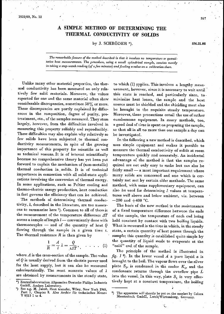
The basis of the new method is the maintenanceof a fixed temperature difference between the endsof the sample, the temperature of each end beingheld constant by contact with two boiling liquids,What is measured is the time in which, in the steadystate, a certain quantity of heat passes through thesample; this quantity is established quite simple bythe quantity of liquid made to evaporate at the"cold" end of the sample.The principle of the method is illustrated in
jig. 1 2). In the lower vessel A a pure liquid a isbrought to the boil. The vapour flows over the silverplate SI' is condensed in the cooler Kl' and th~condensate returns through the overflow pipe Linto the vessel.Tn this way, plate SI is very effec-tively kept at a constant temperature, the boiling
I
2) The apparatus will shortly he put on the market by ColoraMesstechnik GmbH, Lorch/Würtemberg, Germany.
.,- .
358 , PHILIPS TECHNICAL REVIEW VOLUME 21
~-------------' -- G
8
Fig. 1. Principle of the new method of determining the ther-mal conductivity of solids. P sample of material under in-vestigation. A and G vessels containing two different liquids(a and g). W heating element that keeps a on the boil. S2 andSl silver plates, ensuring good thermal contact of P with theliquid g and the vapour of a, respectively. Kl condenser and Loverflowpipe for returning the condensate of a. The liquid g,whose boiling point is roughly 10°C lower than that of a,is brought to the boil by the heat transmitted through thesample P. K2 condenser and B tube, graduated in millilitres,for collecting and indicating the vaporated quantity ofliquid g.
point Ta of the liquid, for if 81drops only slightlybelow that temperature, vapour condenses on the, plate and transfers to it its heat of condensation,causing the remperature of the plate to rise again toTa. The upper vessel G contains another pure liquid,g, whose boiling point is; say, 10°C lower than thatof liquid a. At the bottom of this vessel there isanother silver plate, S2' Fitted 'between the twoplates, SI and 82, is 'a cylindrical sample P of thematerial under investigation. The heat that flowsthrough this sample from SI to 82 brings the liquidg to the boil, thereby keeping the temperature of82constant at the boiling point Tg of g. Between
the two silver plates there is therefore a constanttemperature difference Ta-Tg. The vapour from
liquid g' is condensed in the cool~r [(2 and thecondensate is collected in a tube B,marked with amillilitre scale. .
As soon as the steady state of heat flow is reached- which is 'reached when about 0.1 ml of conden-sate has collected in B'- the time t taken for a cer-tain liquid volume V, say 1 ml, to flow into. B isdetermined with a stop watch. Let S he the heat ofvaporization of the liquid g per 'unit volume, theneq. (1) gives:
A=_!_~=_: VSA R A t(Ta-Tg)
(2)
Given the data on the liquids and the dimensions1 and A of the sample we can calculate A from themeasured values of V and t.
The method shows a remarkably high degree ofaccuracy, owing to the fact that the effect of heatlosses between 81and the liquid g is kept relativelyvery low. This is done primarily by choosing thedimensions of the sample so as to ensure a reason-ably large heat flow through the sample. For in-stance, if the substance is a poor conductor of heat,the sample taken will be in the form of a thin disc.For a better conductor, assuming the same tem-perature difference, a thicker sample will be taken,for an unduly large heat flowwould cause the liquidg to boil too turbulently, with the risk of liquidsplashing over into tube B. Furthermore, if theappropriate quantity of liquid distils too quicklyinto B, the time measurement is less accurate. Thetime t should preferably be between 100 and 1000seconds, and this can be arranged not only by asuitable choice of the thermal resistance of thesample but also by using suitable liquids (fixing thevalues of 8 and Ta and Tg).
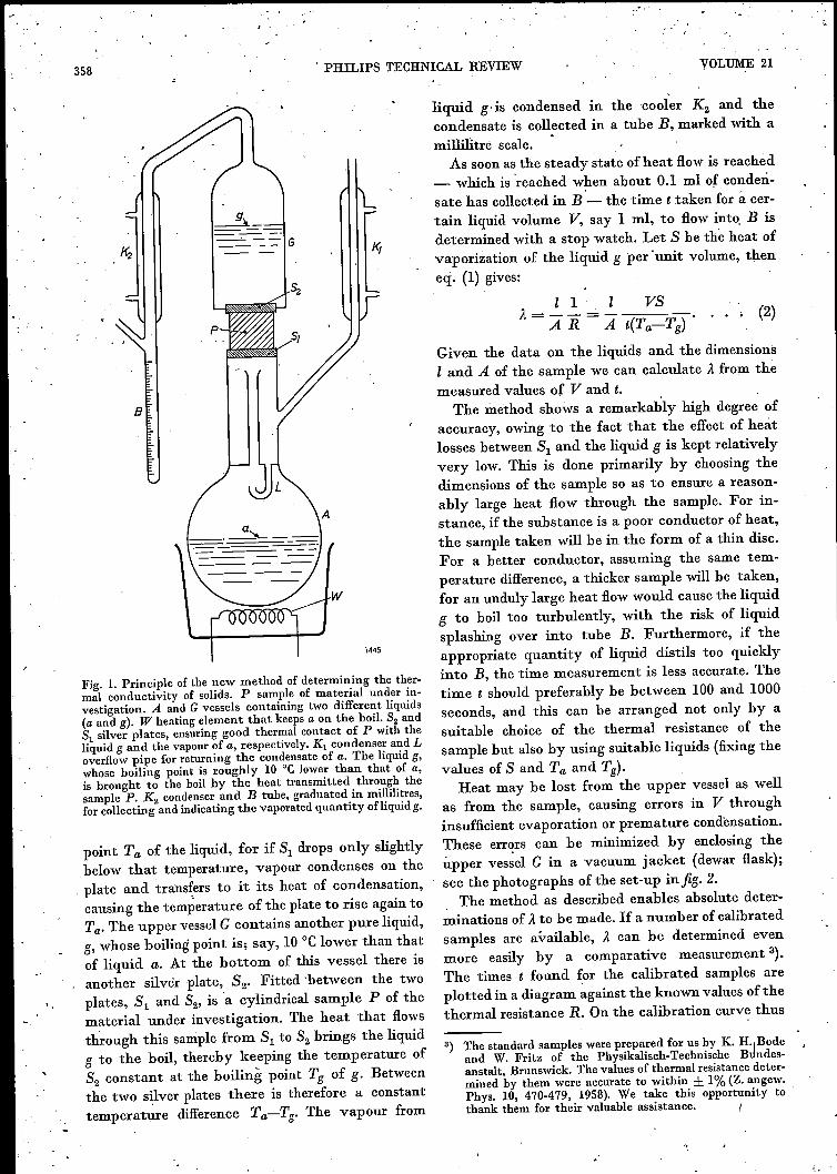
Heat may be lost from the upper vessel as wellas from the sample, causing errors in V throughinsufficient evaporation or premature eondensation,These err~rs can be minimized by enclosing theupper vessel G in a vacuum jacket (dewar flask);see the photographs of the set-up infig. 2.
The method as described enables absolute deter-minations of A to be made. If a number of calibratedsamples are available, A can be determined evenmore easily by a comparative measurement 3).The times t found for the calibrated samples areplotted in a diagram against the known values of thethermal resistance R. On the calibration curve thus
3) The standard samples were prepared for us by K. H·1Bodeand W. Fritz of the Physikalisch-Technische Bundes-anstalt, Brunswick. The values of thermal resistance deter-mined by them were accurate to within ± 1% (Z. angew.Phys. 10, 470-479, 1958). We take this opportunity tothank them for their valuable assistance. I

1959/60, No. 12 DETERMINATION OF THE THERMAL CONDUCTIVITY 359
aD•1612Fig. 2. The apparatus, a) ready for use, b) partially dismantled(for this photograph the sample P was suspended by a threadbetween the two silver plates 51 and 52)'
The upper vessel G is in the form of a dewar flask, with thesealed-off pinch at the top and the condenser K2 and graduatedtube B at the side. It is placed over the sample and presseddown by the long helical spring C. K2 and B are balanced byan arm with the weight H. One of the rings D is placed aroundthe sample to give thermal insulation. A refinement not shownin the arrangement in fig. lis a double-walled glass vessel Esurrounding the sample; between the walls the vapour can becirculated of a liquid whose boiling point is between those ofa and g. The vessel containing this liquid can be seen insidevessel A, and associated with it is a condenser K3 with returnpipe.
obtained we can then, after having measured thetime t, read off directly the value of R for a givensample, and from this value, together with the di-mensions of the sample, we can calculate the valueof À.
It should be noted that for these relative meas-urements it is not necessary to know thc exact valuesof V, Ta and Tg. This at once eliminates the errorsthat can creep into a calculated À value if a) theboiling points Ta and Tg should differ slightly fromthe assumed values owing to impurity of the liquids,and if b) the ends of the sample should not attainthe exact temperatures Ta and Tg owing to contactresistances to the heat transfer between the silverplates and the sample. It should of course be en-sured that these resistances are equal for all meas-urements, in order to obtain reproducible results.
b
The same applies to the magnitude of the smallresidual heat loss, to which we shall return presently.
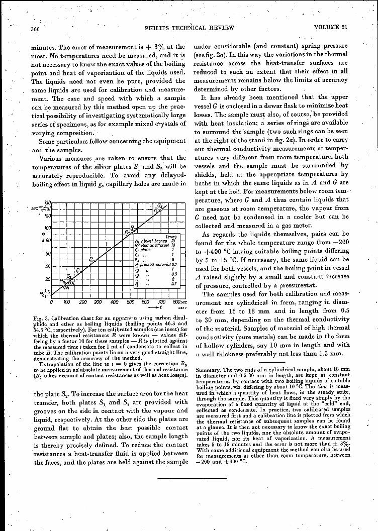
The calibration curve, as can be seen in jig. 3,is very closely a straight line. The negligible spreadof the points is evidence of the high degree of repro-ducibility of which the method is capable. Accordingto eq. (1) the curve should be a straight line throughthe origin. In the diagram this is not so, the linecutting off a section Ro on the ordinate axis. Thiscorresponds to the thermal resistance of the variousheat-transfer surfaces. For each pair ofliquids usedthe calibration line must be plotted afresh, but sinceit is a straight line it is sufficient to measure twostandard samples, possibly with a third for verifi-cation.By this comparative method, a measurement,
including the preparation, lasts no more than 5 to 15
"
360,
PHILIPS TECHNICAL REVIEW VOLUME 21
minutes. The error of measurement is ± 3% at themost. No temperatures need be measured, ana it isnot necessary to know the exact values of the boilingpoint and. heat of vaporization of the liquids used.The liquids need not even be pure, provided thesame liquids are used for calibration and measure-ment. The ease and speed with which a samplecan he measured by this method open up the prac-tical possibility of investigating systematically largeseries of specimens, as for example mixed crystals ofvarying composition.
Some particulars follow concerning the equipmentand the samples.Various measures, are taken to ensure that the
temperatures of the silver plates SI and S2 will heaccurately reproducible. To avoid any delayed-boiling effect in liquid g, capillary holes are made in
Fig. 3. Calibration chart for an apparatus using carbon disul-phide and ether as boiling liquids (boiling points 46,3 and34.5°C,respectively). For ten calibrated samples (see inset) forwhich the thermal resistances R were known - values dif-fering by a factor 10 for these samples - R is plotted againstthe measured time t taken for 1 mI of condensate to collect intube B. The calibration points lie on a very good straight line,demonstrating the accuracy of the method.Extrapolation of the line to t = 0 gives the correction Ru
to be applied in an'absolute measurement of thermal resistance(Ru takes account of contact resistances as weIl as heat losses).
.the plate S2' To increase the surface area for the heattransfer, both plates SI and S2 are provided withgr<?oveson the side in contact with the vapour andliquid, respectively. At the other side the plates areground flat to obtain the best possible contactbetween sample and plates; also, the sample lengthis thereby precisely defined. To reduce the contactresistances a heat-transfer fluid is applied betweenthe faces, and the plates are held against the sample
under considerable (and constant) spring pressure(seefig. 2a). In this way thevariationsin thethermalresistance across the heat-transfer surfaces arereduced to such' an extent that their effect in allmeasurements remains below the limits of accuracydetermined by other factors.
It has already been mentioned that the uppervessel G is enclosed in a dewar flask to minimize heatlosses. The sample must also, of course; be providedwith heat insulation; a series of rings are availableto 'surround the sample (two such rings can be seenat the right ofthe stand in fig. 2a). In order to carryout thermal conductivity measurements at temper-atures very different from room temperature, bothvessels and the sample must be surrounded byshields, held at the appropriate temperatures bybaths in which the same liquids as in A and Garekept at the boil. For measurements below room tem- 'pèrature, where G and A thus contain liquids thatare gaseous at room temperature, the vapour fromG need not be condensed in a cooler but can becollected and measured in a gas meter.As regards the liquids themselves, pairs can be
found for the whole temperature range from -200to +4,00 oe having suitable boiling points differingby 5 to 15 oe. If necessary, the same liquid can beused for both vessels, and the boiling point in vesselA raised slightly by a small and constant increaseof pressure, controlled by a pressurestat.
The samples used for both calibration and meas-urement are cylindrical in form, ranging in diam-eter from 16 to 18 mm and in length from 0.5to 30 mm, depending on the thermal conductivityof the material. Samples of materialof high thermalconductivity (pure metals) can be made in the formof hollow cylinders, say 10 mm in length and witha wall thickness preferably not less than 1.5 mm.
Summary. The two ends of a cylindrical sample, about 18mmin diameter and 0.5-30 mm in length, are kept at constanttemperatures, by contact with two boiling liquids of suitableboiling points, viz. differingby about 10°C. The time is meas-ured in which a quantity of heat flows, in the steady state,through the sample. This quantity is fixed very simply by theevaporation of a fixed quantity of liquid at the "cold" end,collected as condensate. In practice, two calibrated samplesare measured first and a calibration line is plotted from whichthe thermal resistance of subsequent samples can be foundat a glance. It is then not necessary to know the exact boilingpoints of the two liquids, nor the absolute amount of evapo-rated liquid, nor its heat of vaporization. A measurementtakes 5 to 15 minutes and the error is not more than ± 3%.With some additional equipment the method can also be usedfor measurements at other than room temperature, between-200 and +.400 °C.

1959/60, No. 12
CHEMICAL FORMULATION OF RADIO-ISOTOPES
The photograph shows a part of the IsotopeLaboratory of N.V. Philips Duphar in Amsterdam,where radio-isotopes produced in the Amsterdamcyclotron or in reactors at Kjeller (Norway), Mol(Belgium) or Saclay (France) are chemically pro-cessed. Among the isotopes handled are nIl, I98Au,206Bi,etc. Workers in the laboratory are protectedfrom radiation hazards by performing all operationsbehind a thick lead wall, in fume cupboards withan underpressure of several cm water. The lattermeasure is to prevent contamination of the labora-tory atmosphere by radioactive dust. A furthersafety measure is that all workers in the laboratorywear special clothing.Manipulations of the radioactive substances are
carried out with the aid of the usual remotely-controlled tongs. The man in the foreground isoperating such a device. Windows of lead glass20 cm thick make it possible to direct the tongs andfollow the process. On the panel above the lead wallare cocks admitting water, steam, air, vacuum andcertain standard reagents to the reaction vessel. Ofthe projecting rods on the panel, some serve for theopening and closing of the passage connecting onefume cupboard with the next, while others are for
the operation of a balance for weighing the radio-active materials. The balance scale is visible on aground-glass plate contained in the box seen justabove the fume cupboard.The fume cupboard at which the operator is busy
is a pipetting cupboard, for transferring measuredquantities of radioactive solutions. On the left of theoperator are two rubber squeezers for sucking thesolutions into the pipettes. In the cupboard on theleft preparations for medical use can bc sterilized.The two knobs between the two lead-glass windowsopen and close the autoclaves.The fume cupboards are accessible only from
underneath through special doors. The operator inthe background is moving a transportable vesselcontaining the radioactive raw material to a positionunder the door of a fume cupboard. The guides inthe floor ensure that the vessel is placed preciselyunder the door. The vessel is then raised until it justtouches the door; the latter is opened from outside,whereupon the vessel is raised further into the cup-board. The contents may now be manipulated in thefume cupboard. The same procedure in the reverseorder accomplishes removal of the vessel and closingof the door.
361
Related Documents