A simple graphic way to reduce stress concentrations by growth C. Mattheck, I. Tesari, A. Sauer, K. Bethge & O. Kraft Forschungszentrum Karlsruhe GmbH, Institute for Materials Research II, Hermann-von-Helmholtz-Platz 1, D-76344 Eggenstein-Leopoldshafen, Germany Abstract During millions of years biological load bearing structures are highly adapted to their natural loading. Due to the evolution not only the material and shape itself but also the designing mechanism is optimized. Trees for example try to avoid stress peaks and to homogenize the stress distribution on their surface. This advantageous stress state is realized by load-adaptive growth. It enlarges the load capacity and lifetime as well as reduces the waste of material, which are important demands also in engineering. The shape optimization of engineering components by computer simulation of adaptive growth was started in the late eighties in the Karlsruhe Research Centre. It was based on the use of the Finite-Element-Method (FEM) and has been called Computer Aided Optimization (CAO). Now, about 15 years after the CAO-method a drastic simplification is developed. So notch shape optimization in many cases can be done without the use of FEM, only with an easy graphic method, called ‘‘Method of Tensile Triangles’’. Like buttress roots in trees the method bridges a corner-like notch with tensile loaded triangles. The notch shape found with it may be scaled up and down according to the individual design space limitations. Fitted as a formula it can be implemented into a CAD-System, that means: shape optimization by mouse-click. The method is adjustable for multi-axial loading situations and can also be used for saving weight by removing unloaded areas in engineering structures. Keywords: shape optimization, stress concentration, design rules, fatigue. www.witpress.com, ISSN 1743-3541 (on-line) © 2008 WIT Press WIT Transactions on Ecology and the Environment, Vol 114, Design and Nature IV 79 doi:10.2495/DN080091

Welcome message from author
This document is posted to help you gain knowledge. Please leave a comment to let me know what you think about it! Share it to your friends and learn new things together.
Transcript
A simple graphic way to reduce stress concentrations by growth
C. Mattheck, I. Tesari, A. Sauer, K. Bethge & O. Kraft Forschungszentrum Karlsruhe GmbH, Institute for Materials Research II, Hermann-von-Helmholtz-Platz 1, D-76344 Eggenstein-Leopoldshafen, Germany
Abstract
During millions of years biological load bearing structures are highly adapted to their natural loading. Due to the evolution not only the material and shape itself but also the designing mechanism is optimized. Trees for example try to avoid stress peaks and to homogenize the stress distribution on their surface. This advantageous stress state is realized by load-adaptive growth. It enlarges the load capacity and lifetime as well as reduces the waste of material, which are important demands also in engineering. The shape optimization of engineering components by computer simulation of adaptive growth was started in the late eighties in the Karlsruhe Research Centre. It was based on the use of the Finite-Element-Method (FEM) and has been called Computer Aided Optimization (CAO). Now, about 15 years after the CAO-method a drastic simplification is developed. So notch shape optimization in many cases can be done without the use of FEM, only with an easy graphic method, called ‘‘Method of Tensile Triangles’’. Like buttress roots in trees the method bridges a corner-like notch with tensile loaded triangles. The notch shape found with it may be scaled up and down according to the individual design space limitations. Fitted as a formula it can be implemented into a CAD-System, that means: shape optimization by mouse-click. The method is adjustable for multi-axial loading situations and can also be used for saving weight by removing unloaded areas in engineering structures. Keywords: shape optimization, stress concentration, design rules, fatigue.
www.witpress.com, ISSN 1743-3541 (on-line)
© 2008 WIT PressWIT Transactions on Ecology and the Environment, Vol 114,
Design and Nature IV 79
doi:10.2495/DN080091
1 Introduction
Good mechanical constructions are reliable during their estimated lifetime, light-weighted and have a high load-capability. A main reason for failure are local stress concentrations on the surface of a component which cause material fatigue during its lifetime. Therefore, a prevention of such stress-raising effects is of great importance in nature as well as in engineering design. Trees make any effort to grow into a homogeneous state of stress on their surface. The outermost annual ring always tries to adapt to external loading by locally increased or reduced growth according to high or low stresses [1]. Computer Aided Optimization CAO [2] simulates this effect by a Finite Element calculation with a fictitious thermal expansion dependent on previously calculated stresses, whereas high stresses lead to a great thermal expansion and vice versa. The component starts to grow in the highly loaded zones and, in analogy to trees, forms the locally thickest “annual rings”. By this, the stress peaks will be reduced. The procedure is done iteratively until a constant stress state on the surface is achieved. Even if the computer stays rather affordable, become increasingly powerful and computer based methods for structural optimization like CAO are used by a lot of bigger companies, most companies are not able to afford the expenditure for expensive FEM-software and the highly qualified staff which is needed for the use of this elaborate tool. Therefore an efficient and easy to use optimization method is needed to implement optimization as standard in designing process. Now, about 15 years after the CAO-method the ‘Method of Tensile Triangles’ has been developed. It is an easy graphic optimization method following the design rules of nature.
2 Method of Tensile Triangles
2.1 Growth at highly loaded areas
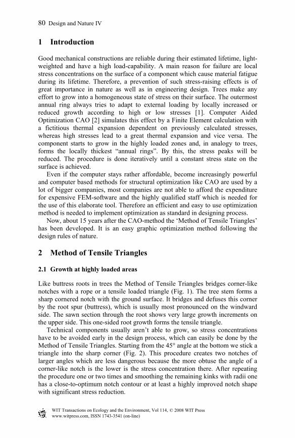
Like buttress roots in trees the Method of Tensile Triangles bridges corner-like notches with a rope or a tensile loaded triangle (Fig. 1). The tree stem forms a sharp cornered notch with the ground surface. It bridges and defuses this corner by the root spur (buttress), which is usually most pronounced on the windward side. The sawn section through the root shows very large growth increments on the upper side. This one-sided root growth forms the tensile triangle. Technical components usually aren’t able to grow, so stress concentrations have to be avoided early in the design process, which can easily be done by the Method of Tensile Triangles. Starting from the 45° angle at the bottom we stick a triangle into the sharp corner (Fig. 2). This procedure creates two notches of larger angles which are less dangerous because the more obtuse the angle of a corner-like notch is the lower is the stress concentration there. After repeating the procedure one or two times and smoothing the remaining kinks with radii one has a close-to-optimum notch contour or at least a highly improved notch shape with significant stress reduction.
www.witpress.com, ISSN 1743-3541 (on-line)
© 2008 WIT PressWIT Transactions on Ecology and the Environment, Vol 114,
80 Design and Nature IV
Figure 1: Biological inspiration for the method of Tensile Triangles: The buttress root bridges the kink at the base of a tree, like a rope [3].
Figure 2: Procedure of the Method of Tensile Triangles for a corner transition [3]. First the corner is bridged with some triangles. Finally, the remaining kinks have to be rounded by circles.
www.witpress.com, ISSN 1743-3541 (on-line)
© 2008 WIT PressWIT Transactions on Ecology and the Environment, Vol 114,
Design and Nature IV 81
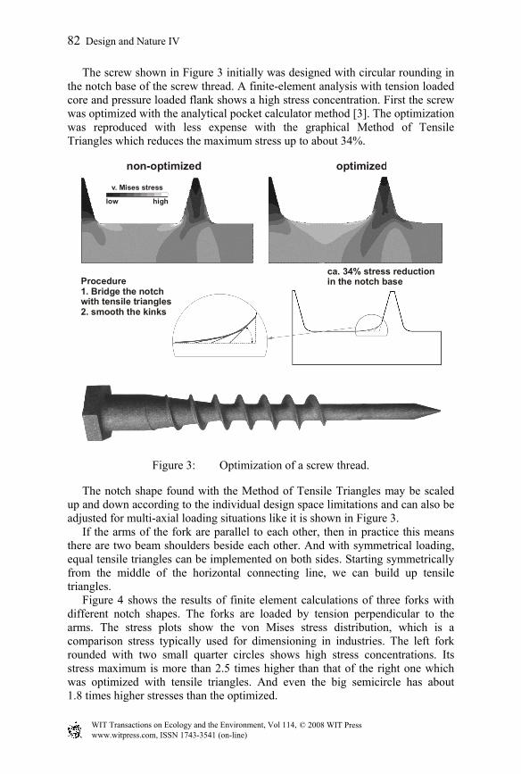
The screw shown in Figure 3 initially was designed with circular rounding in the notch base of the screw thread. A finite-element analysis with tension loaded core and pressure loaded flank shows a high stress concentration. First the screw was optimized with the analytical pocket calculator method [3]. The optimization was reproduced with less expense with the graphical Method of Tensile Triangles which reduces the maximum stress up to about 34%.
non-optimized optimized
Procedure1. Bridge the notch with tensile triangles2. smooth the kinks
ca. 34% stress reductionin the notch base
v. Mises stress
low high
Figure 3: Optimization of a screw thread.
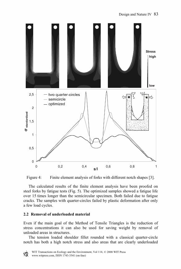
The notch shape found with the Method of Tensile Triangles may be scaled up and down according to the individual design space limitations and can also be adjusted for multi-axial loading situations like it is shown in Figure 3. If the arms of the fork are parallel to each other, then in practice this means there are two beam shoulders beside each other. And with symmetrical loading, equal tensile triangles can be implemented on both sides. Starting symmetrically from the middle of the horizontal connecting line, we can build up tensile triangles. Figure 4 shows the results of finite element calculations of three forks with different notch shapes. The forks are loaded by tension perpendicular to the arms. The stress plots show the von Mises stress distribution, which is a comparison stress typically used for dimensioning in industries. The left fork rounded with two small quarter circles shows high stress concentrations. Its stress maximum is more than 2.5 times higher than that of the right one which was optimized with tensile triangles. And even the big semicircle has about 1.8 times higher stresses than the optimized.
www.witpress.com, ISSN 1743-3541 (on-line)
© 2008 WIT PressWIT Transactions on Ecology and the Environment, Vol 114,
82 Design and Nature IV
Stresshigh
low
Figure 4: Finite element analysis of forks with different notch shapes [3].
The calculated results of the finite element analysis have been proofed on steel forks by fatigue tests (Fig. 5). The optimized samples showed a fatigue life over 15 times longer than the semicircular specimen. Both failed due to fatigue cracks. The samples with quarter-circles failed by plastic deformation after only a few load cycles.
2.2 Removal of underloaded material
Even if the main goal of the Method of Tensile Triangles is the reduction of stress concentrations it can also be used for saving weight by removal of unloaded areas in structures. The tension loaded shoulder fillet rounded with a classical quarter-circle notch has both a high notch stress and also areas that are clearly underloaded
www.witpress.com, ISSN 1743-3541 (on-line)
© 2008 WIT PressWIT Transactions on Ecology and the Environment, Vol 114,
Design and Nature IV 83
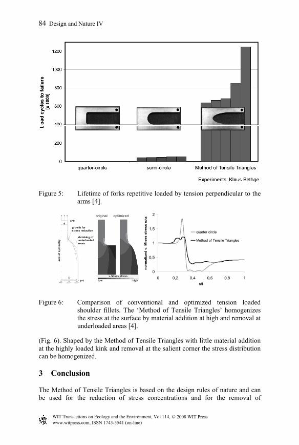
Figure 5: Lifetime of forks repetitive loaded by tension perpendicular to the
arms [4].
shrinking ofunderloadedareas
growth for stress reduction
s=1
axis
of s
ymm
etry
d
D
s=0
0
0,5
1
1,5
2
0 0,2 0,4 0,6 0,8 1s/l
norm
aliz
edv.
Mis
esst
ress
σ/σ 0
quarter circle
Method of Tensile Triangles
original optimized
v. Mises stresslow high
Figure 6: Comparison of conventional and optimized tension loaded shoulder fillets. The ‘Method of Tensile Triangles’ homogenizes the stress at the surface by material addition at high and removal at underloaded areas [4].
(Fig. 6). Shaped by the Method of Tensile Triangles with little material addition at the highly loaded kink and removal at the salient corner the stress distribution can be homogenized.
3 Conclusion
The Method of Tensile Triangles is based on the design rules of nature and can be used for the reduction of stress concentrations and for the removal of
www.witpress.com, ISSN 1743-3541 (on-line)
© 2008 WIT PressWIT Transactions on Ecology and the Environment, Vol 114,
84 Design and Nature IV

underloaded parts in technical components. A major advantage is that neither finite element analysis nor complex mathematics is necessary for this graphic method of shape optimization. More Information about the method can be found at www.mattheck.de.
References
[1] Mattheck, C., Why they grow, how they grow - the mechanics of trees, Arboricultural J., Vol. 14, pp 1–17, 1990.
[2] Mattheck, C. & Burkhardt, S., A new method of structural shape optimization based on biological growth, International Journal of Fatigue, Vol. 12, pp. 185–190, 1990.
[3] Mattheck C., The face of failure – in nature and engineering, Verlag Forschungszentrum Karlsruhe GmbH (2004).
[4] Mattheck, C., Secret design rules of nature - Optimum shapes without computers. Verlag Forschungszentrum Karlsruhe GmbH (2007).
[5] Sauer, A., Untersuchungen zur Vereinfachung biomechanisch inspirierter Strukturoptimierung. Verlag Forschungszentrum Karlsruhe GmbH (2008).
www.witpress.com, ISSN 1743-3541 (on-line)
© 2008 WIT PressWIT Transactions on Ecology and the Environment, Vol 114,
Design and Nature IV 85
Related Documents