A simple and efficient Road Detection Algorithm for Real Time Autonomous Navigation based on Monocular Vision A. Miranda, Neto, and L. Rittner Abstract- Navigation of a Mobile Robot is based on its interaction with the environment, through information acquired by sensors. By incorporating several kinds of sensors in autonomous vehicles, it is possible to improve their autonomy and "intelligence", specially regarding Mobile Robot Navigation in unknown environment. The type and number of sensors determines the data volume necessary for the processing and composition of the image from the environment. Nevertheless, the excess of information imposes a great computational cost in data processing. Currently many applications for control of autonomous vehicles are being developed, for example, the Grand Challenge, world-wide championship organized by DARPA (Defense Advanced Research Projects Agency). Machine Vision is, together with a set of sensors, one of the tools used in the championship. In our work, we propose a Mobile Robot Navigation Software based in monocular vision. Our system is organized in hierarchic and independent layers, with distributed processing. After reading an image, the system processes, segments and identifies the navigation area (road detection), that will be used as input by a motion generator system. The considered system is based on images acquired by a single camera and uses simple filtering and thresholding techniques, which make it fast and efficient for real time navigation. Index Terms- Mobile Robots, Autonomous Vehicles, Navigation, Machine Vision, Image Segmentation. I. INTRODUCTION Lately, several applications for control of autonomous vehicles are being developed, and in most cases, the machine vision is an important part of the set of sensors used for the navigation. Perhaps this happens because we want to reproduce human vision in machines. According to Gonzalez and Woods in [1], the acquisition of values sampled by a camera (vision) can be compared with image processing performed by human vision (role played by the eye jointly with the brain). In a few words, the human vision allows the light of an object outside the eye to become image in the retina (more internal membrane of the eye). The perception of this image happens due to the excitement of Manuscript received August 7, 2006. This work was supported in part by CNPq. Arthur de Miranda Neto is with UNICAMP, Campinas - SP, 13083- 852 Brazil, phone: 55-19-3521-3823; (e-mail: arthur ofem.unicamp.br). Leticia Rittner is with UNICAMP, Campinas - SP, 13083-852 Brazil (e- mail: lrittner adca.fee.unicamp.br). light receivers, that transform the radiating energy into electric pulses that later are decoded by the brain. In the other hand, it is known that the human vision without assistance from the brain is not capable to allow people displacement (navigation) in an efficient way. This is also truth for computer systems, which in order to navigate based on images, should contain software intelligent enough to manage mechanical structure through navigation. Although extremely complex and highly demanding, thanks to the great deal of information it can deliver (it has been estimated that humans perceive visually about 90°0 of the environment information required for driving), machine vision is a powerful means for sensing the environment and has been widely employed to deal with a large number of tasks in the automotive field [2]. With the purpose to study machine vision techniques applied to the navigation of autonomous vehicles, the world- wide championship organized by the DARPA (Defense Advanced Research Projects Agency) [3], [4], known as Grand Challenge, was one of our motivations for the accomplishment of this work. In general, the participant vehicles of this competition are equipped with all kinds of sensors to allow the interface between the navigation system and the environment to be explored. The vision system usually used in these vehicles is composed by two or more cameras, as we see in [5] and [6]. In our work, a single sensor (monocular vision) will be considered, or either, a camera will acquire images (samples) of the environment and these will feed the computer system. What is trivial for the human system, that is, to construct three-dimensional scenes from two-dimensional images captured by the vision system and to use it on the decision process for navigation, is not necessary trivial for the computer systems. Different from the human system, complex computational vision systems can lead to some damages due to the processing time. Thinking about the existing relation between a real time decision system and an image reading system that operates in a specific acquiring/reading rate, that is, amount of images read per second, one can question: how many images acquired must be discarded by the image processing system to guarantee an acceptable real time navigation of an autonomous vehicle? Therefore, the decision for a more complex machine vision system possibly leads to an excessively slow system for an independent real time application. Additionally, the automatic 92 1-4244-0537-8/06/$20.00 ©2006 IEEE

Welcome message from author
This document is posted to help you gain knowledge. Please leave a comment to let me know what you think about it! Share it to your friends and learn new things together.
Transcript

A simple and efficient Road DetectionAlgorithm for Real Time Autonomous
Navigation based on Monocular Vision
A. Miranda, Neto, and L. Rittner
Abstract- Navigation of a Mobile Robot is based on itsinteraction with the environment, through information acquiredby sensors. By incorporating several kinds of sensors inautonomous vehicles, it is possible to improve their autonomyand "intelligence", specially regarding Mobile Robot Navigationin unknown environment. The type and number of sensorsdetermines the data volume necessary for the processing andcomposition of the image from the environment. Nevertheless, theexcess of information imposes a great computational cost in dataprocessing. Currently many applications for control ofautonomous vehicles are being developed, for example, theGrand Challenge, world-wide championship organized byDARPA (Defense Advanced Research Projects Agency). MachineVision is, together with a set of sensors, one of the tools used inthe championship. In our work, we propose a Mobile RobotNavigation Software based in monocular vision. Our system isorganized in hierarchic and independent layers, with distributedprocessing. After reading an image, the system processes,segments and identifies the navigation area (road detection), thatwill be used as input by a motion generator system. Theconsidered system is based on images acquired by a singlecamera and uses simple filtering and thresholding techniques,which make it fast and efficient for real time navigation.
Index Terms- Mobile Robots, Autonomous Vehicles,Navigation, Machine Vision, Image Segmentation.
I. INTRODUCTION
Lately, several applications for control of autonomousvehicles are being developed, and in most cases, the machinevision is an important part of the set of sensors used for thenavigation. Perhaps this happens because we want toreproduce human vision in machines.
According to Gonzalez and Woods in [1], the acquisition ofvalues sampled by a camera (vision) can be compared withimage processing performed by human vision (role played bythe eye jointly with the brain). In a few words, the humanvision allows the light of an object outside the eye to becomeimage in the retina (more internal membrane of the eye). Theperception of this image happens due to the excitement of
Manuscript received August 7, 2006. This work was supported in part byCNPq. Arthur de Miranda Neto is with UNICAMP, Campinas - SP, 13083-852 Brazil, phone: 55-19-3521-3823; (e-mail: arthur ofem.unicamp.br).
Leticia Rittner is with UNICAMP, Campinas - SP, 13083-852 Brazil (e-mail: lrittner adca.fee.unicamp.br).
light receivers, that transform the radiating energy into electricpulses that later are decoded by the brain.
In the other hand, it is known that the human visionwithout assistance from the brain is not capable to allowpeople displacement (navigation) in an efficient way. This isalso truth for computer systems, which in order to navigatebased on images, should contain software intelligent enough tomanage mechanical structure through navigation.
Although extremely complex and highly demanding, thanksto the great deal of information it can deliver (it has beenestimated that humans perceive visually about 90°0 of theenvironment information required for driving), machine visionis a powerful means for sensing the environment and has beenwidely employed to deal with a large number of tasks in theautomotive field [2].
With the purpose to study machine vision techniquesapplied to the navigation of autonomous vehicles, the world-wide championship organized by the DARPA (DefenseAdvanced Research Projects Agency) [3], [4], known asGrand Challenge, was one of our motivations for theaccomplishment of this work.
In general, the participant vehicles of this competition areequipped with all kinds of sensors to allow the interfacebetween the navigation system and the environment to beexplored. The vision system usually used in these vehicles iscomposed by two or more cameras, as we see in [5] and [6]. Inour work, a single sensor (monocular vision) will beconsidered, or either, a camera will acquire images (samples)of the environment and these will feed the computer system.What is trivial for the human system, that is, to construct
three-dimensional scenes from two-dimensional imagescaptured by the vision system and to use it on the decisionprocess for navigation, is not necessary trivial for thecomputer systems.
Different from the human system, complex computationalvision systems can lead to some damages due to theprocessing time. Thinking about the existing relation betweena real time decision system and an image reading system thatoperates in a specific acquiring/reading rate, that is, amount ofimages read per second, one can question: how many imagesacquired must be discarded by the image processing system toguarantee an acceptable real time navigation of anautonomous vehicle?
Therefore, the decision for a more complex machine visionsystem possibly leads to an excessively slow system for anindependent real time application. Additionally, the automatic
921-4244-0537-8/06/$20.00 ©2006 IEEE
discarding choice of information (images) by the system, for itto become fast enough, can result in loss of importantinformation.
Although the system could maintain a database of acquiredimages and submits it, for example, to a neural network fordecision, the great number of information not necessarilywould lead to better decisions and also could harm theperformance of the system, overloading it.Due to the general applicability of it, the problem of
navigation of mobile robots is dealt with using more complextechniques [2]. The most common ones are based on theprocessing of two or more images, such as the analysis of theoptical flow field and the processing of non-monocularimages.
In the first case more than one image are acquired by thesame sensor in different time instants, while in the second onemultiple cameras acquire images simultaneously, but fromdifferent points of view. Besides their intrinsic highercomputational complexity caused by a significant increment inthe amount of data to be processed, these techniques must alsobe robust enough to tolerate noise caused by vehiclemovements and drifts in the calibration of the multiplecameras' setup.
The optical flow-based technique requires the analysis of asequence of two or more images: a two-dimensional vector iscomputed in the image domain, encoding the horizontal andvertical components of the velocity of each pixel. The resultcan be used to compute ego-motion, which in some systemsare directly extracted from odometry; obstacles can bedetected by analyzing the difference between the expected andreal velocity fields.Aware that in the majority of the autonomous navigation
systems the machine vision system is working together withother sensors, this work has for purpose to present a method toprocess and analyze images acquired by a single camera(monocular vision). The main purpose is the identification ofthe navigation area in the images. Because it uses simpletechniques and fast algorithms, the system is capable topresent a good performance in real time, where thecommitment between processing time and images acquisitionis fundamental
In section 2 we present an overview of the GrandChallenge, as context for the studied problem. Section 3presents the structure of a Navigation System. In section 4 thestages of image processing acquired for identification of thenavigation area are described. The obtained results arepresented in section 5 and the conclusions and possibleextensions can be found in section 6.
II. GRAND CHALLENGE
A. OverviewThe DARPA (Defense Advanced Research Projects
Agency) is an agency that aims to improve the defense ofU.S.A. in medium and long term. With the intention tostimulate the development of autonomous off-road vehiclesthey decide to organized the first DARPA Grand Challenge in2004. One of the reasons for the creation of the Grand
have one third of its fleet composed by autonomous vehiclesup to 2015. This competition is opened to high schools ofU.S.A. and Universities/Companies inside and outside theU.S.A.. Vehicles of all kinds are allowed.
In 2004 there were 106 competitors inscribed. It took placeon a desert course stretching from Barstow, California toPrimm, Nevada, but did not produce a finisher. CarnegieMellon's Red Team traveled the farthest distance, completing7.4 miles ofthe course.
In 2005, the route to be followed by the robots was suppliedto the teams two hours before the start. Once the race hadstarted, the robots were not allowed to contact humans in anyway. By the end, 18 robots had been disabled and five robotsfinished the course. The winner of the 2005 DARPA GrandChallenge was Stanley, with a course time of 6 hours 53minutes and 8 seconds (6:53:08) with average speed of 19.1MPH (30.7 km/h).
B. Basic Rules
* Vehicle must be entirely autonomous, using onlyGPS and the information it detects with its sensors.
* Vehicles will complete the route by driving betweenspecified checkpoints.
* Vehicles must operate in rain and fog, with GPSblocked.
* Vehicles must avoid collision with vehicles and otherobjects such as carts, bicycles, traffic barrels, andobjects in the environment such as utility poles.
C. Future ofthe ChampionshipThe 2007 Grand Challenge, which is also known as the
DARPA Urban Challenge, will take place on November 3,2007. The course will involve a 60 mile mock urban areacourse, to be completed in fewer than 6 hours. Rules willinclude the obeying of traffic laws while negotiating othertraffic and obstacles and merging into traffic.
III. NAVIGATION SYSTEM
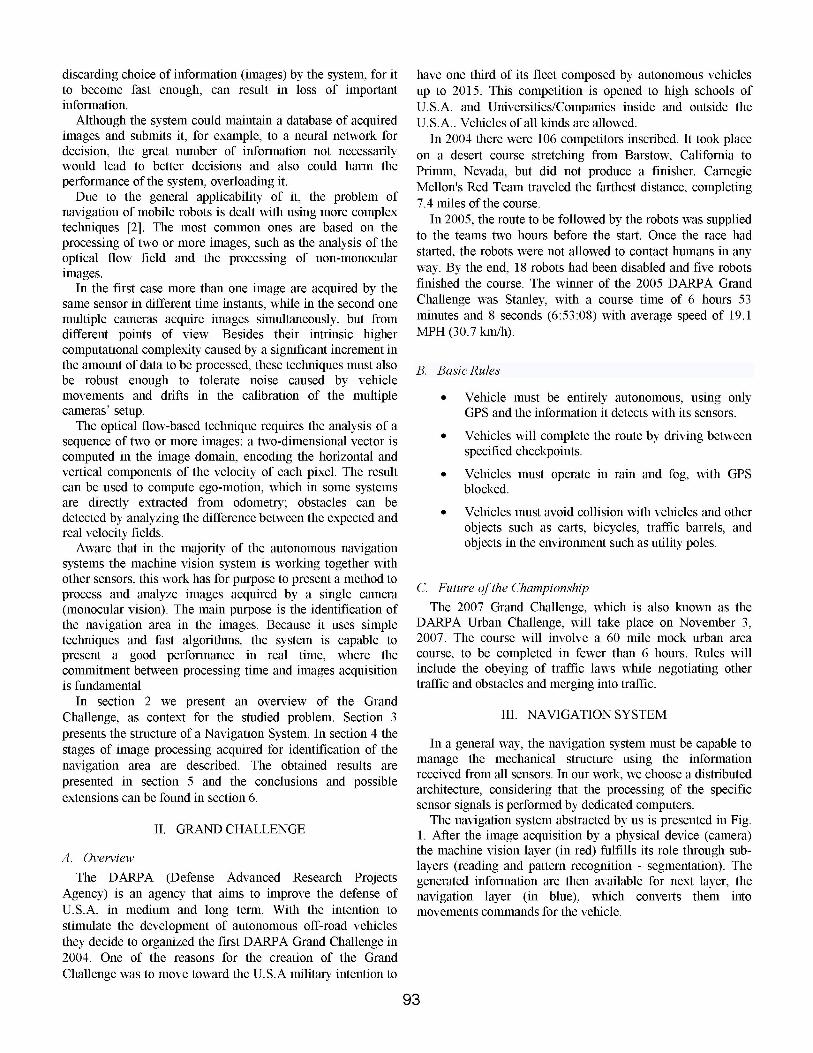
In a general way, the navigation system must be capable tomanage the mechanical structure using the informationreceived from all sensors. In our work, we choose a distributedarchitecture, considering that the processing of the specificsensor signals is performed by dedicated computers.The navigation system abstracted by us is presented in Fig.
1. After the image acquisition by a physical device (camera)the machine vision layer (in red) fulfills its role through sub-layers (reading and pattern recognition - segmentation). Thegenerated information are then available for next layer, thenavigation layer (in blue), which converts them intomovements commands for the vehicle.
Challenge was to move toward the U.S.A military intention to
93
Jr
It is important to point out that our application (software)was developed based on the object oriented paradigm andorganized in layers (multithreading), where each layer istreated as a service (thread). When a layer is composed bysub-layers, they will also be structured as services (threads).According to [7] and [8], the use of object oriented paradigmfacilitates the migration of the software project to thecodification, and the layers structure contributes withapplications running in multiprocessor computers.
This work is focused on our machine vision layerimplementation.
IV. MACHINE VISIONIn general, processes conducted by this layer (machine
vision) have as goal, in addition to the visual information, toprocess image data for machine perception. Its algorithmscarry through operations on images, with the purpose toreduce noise and to segment them.
Several methods can perform pattern recognition in images.These methods, when applied to image processing, generallyare known as segmentation methods. This segmentation,according to Gonzalez and Woods in [1], can be considered as
the partition of digital images in sets of pixels, consideringapplication and previously defined criteria.The purpose of segmentation is to distinguish objects in an
image [9], what can be extremely sophisticated and complex.Results can be very satisfactory with the use of wellelaborated filters. However, these results (high qualitysegmentation) can generate a higher price, that is, normallyrobust segmentation algorithms present great complexity.One way to perform segmentation of an image is to use
thresholds. This type of segmentation technique, calledthresholding, is very simple and fast computationally, howeverthe identification of the ideal threshold can be sufficientlycomplicated. The best thing to do in this case is to use
techniques and algorithms that search the thresholdsautomatically.
Thresholding methods are divided in two groups: global andlocal. The global ones divide the image using only onethreshold and the local ones are those that divide the image insub-images and for each one ofthem a threshold is defined. InSahoo et al. [10] the local thresholds are defined as multilevelthresholds. Summarizing, from the definition of globalthresholds and/or multilevel, the use of a global threshold in atwo-dimensional image I (x, y) with levels of N=[0,255]intensity consists of determining an only threshold T thatseparates pixels in two distinct classes: object and background.Threshold T normally is applied to the histogram of an imageh (N), which can be seen as a description of the distribution ofpixels intensities for the image.
Multilevel thresholds are generally more laborious than theglobal threshold, because it is more complicate to findmultiples thresholds that determine the interest regionseffectively, especially when there are some groups of objectsin the image.On the other hand, according to Gonzalez and Woods [1],
the global thresholding only reaches good results when theillumination of the image is relatively uniform and the interestregions, represented by objects, possess a significantdifference of intensity from the background (contrast), whatprobably it is not the case of the great majority ofenvironments defined for DARPA Grand Challenge.What we propose in this work is a global thresholding
method, which seeks not the ideal threshold for the wholeimage, but an ideal threshold associate to the portion of theimage that interests us for the identification of the navigationarea. Details of this search are described below.
A. Image pre-processingMost research groups face this problem using highly
sophisticated image filtering algorithms. For the most part,gray-level images are used, but in some cases color images areused: this is the case of the MOSFET (Michigan Off-roadSensor Fusing Experimental Testbed) autonomous vehicle,which uses a color segmentation algorithm that maximizes thecontrast between lane markings and road [2].
In this work we use gray-level images and smooth themusing a very simple low-pass filter.
B. Image SegmentationIn this work, the purpose of segmentation is the
identification of the navigation area in the images, that is, theimage classification in two types of objects: Navigation Areaand Obstacles. Right after the images pre-processing, webegin the search for an ideal threshold using a segmentationtechnique proposed by Otsu in [11].
The main characteristic of this method is the maximizationof the variance between classes of the image, that is, themaximization of the separation between object andbackground. The thresholding process is seen as thepartitioning of pixels of an image in two classes: Cl (object)and C2 (background). This method is recursive and searchesthe maximization for the cases: C1 0.1,..., T} and C2 {T+ 1, T + 2,..., N -1}, where T is the chosen threshold and Nthe number of intensity levels of the image.
94
One of the great advantages of this method is that it doesnot restrict itself to the type of histogram of the image, that is,it can be applied to unimodal, bimodal or multimodalhistograms, but it presents better performance in images withbigger intensity variance. Its main disadvantage is itssensitivity to noise in the image, what can be reduced with theapplication of a smoothing filter. On the other hand, Sahoo et.al. in [10] and Lee et. al. in [12] consider this method as one ofthe best choices for real time applications in machine vision.
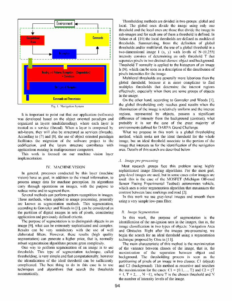
Although the Otsu method is an excellent method to choosean ideal threshold, for all cases it considers the information ofthe image as a whole (global information). Fig. 2 illustratesthat probably, for images that possess in its composition thehorizon, the algorithm does not work well (referred in thiswork as "problem of the horizon").
Fig. 2 - Original Image, Otsu Segmentation and Histogram of pre-processedImage
To cope with this problem, some systems have beendesigned to investigate only a small portion of the road aheadof the vehicle where the absence of other vehicles can beassumed. As an example, the LAKE and SAVE autonomousvehicles rely on the processing of the image portioncorresponding to the nearest 12m of road ahead of the vehicle,and it has been demonstrated that this approach is able tosafely maneuver the vehicle on highways and even on beltways or ramps with a bending radius down to 50m [2].The RALPH (Rapidly Adapting Lateral Position Handler)
system, instead, reduces the portion of the image to beprocessed according to the result of a radar-based obstacledetection module [2].In other systems the area in which lane markings are to be
looked for is determined first. The research group of theLaboratoire Regional des Ponts-et-Chaussees de Strasbourgexploits the assumption that there should always be achromatic contrast between road and off-road (or obstacles), atleast in one color component; to separate the components, theconcept of chromatic saturation is used [2].
In the proposed method, called from now on "TH Finder"(Threshold and Horizon Finder) and based on Otsu method,we decide to divide image in two parts. The division is notnecessarily in equal parts, but in two complementary sub-
images. The explanation for the division is related to the factthat for immediate displacements, human uses the informationthat are close and for future decisions, the information that arein their horizon. In addition to that, smaller parts of an imagecan produce better segmentation results.
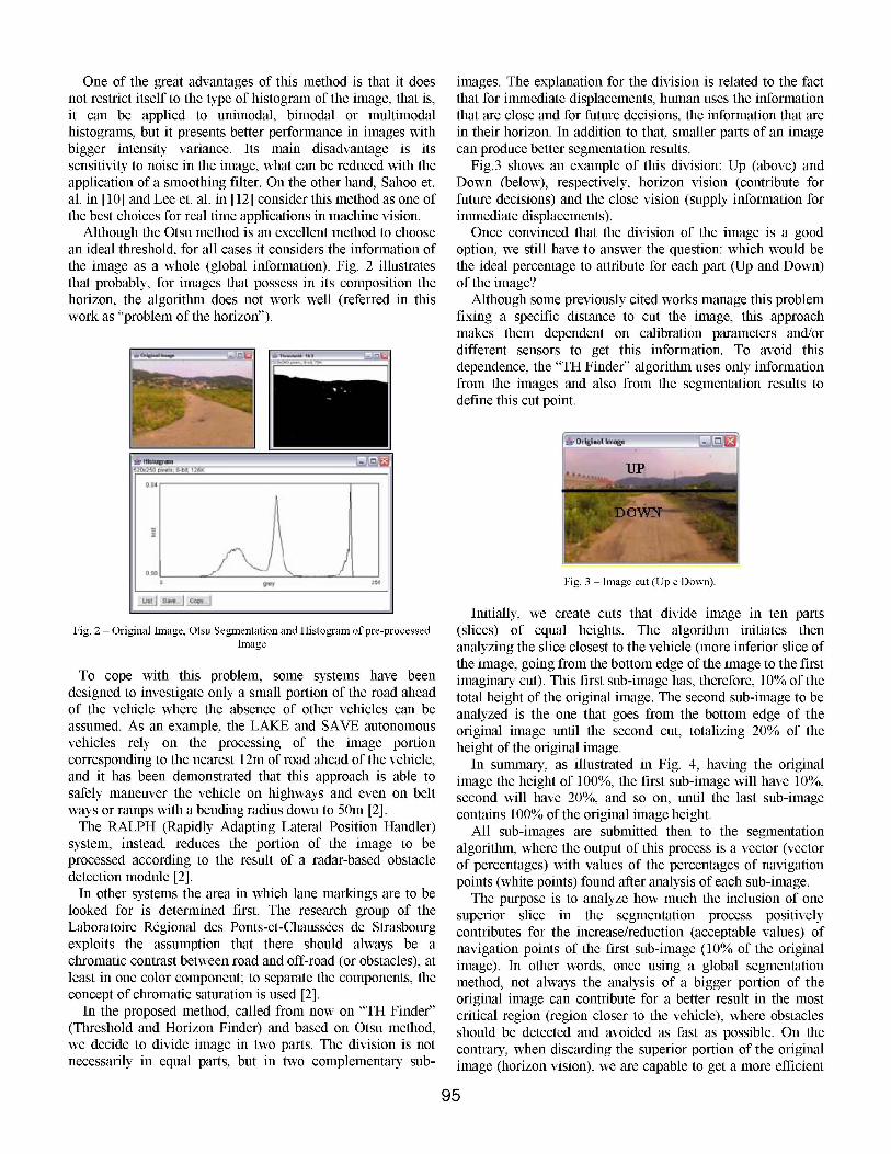
Fig.3 shows an example of this division: Up (above) andDown (below), respectively, horizon vision (contribute forfuture decisions) and the close vision (supply information forimmediate displacements).Once convinced that the division of the image is a good
option, we still have to answer the question: which would bethe ideal percentage to attribute for each part (Up and Down)of the image?
Although some previously cited works manage this problemfixing a specific distance to cut the image, this approachmakes them dependent on calibration parameters and/ordifferent sensors to get this information. To avoid thisdependence, the "TH Finder" algorithm uses only informationfrom the images and also from the segmentation results todefine this cut point.
Fig. 3 - Image cut (Up e Down).
Initially, we create cuts that divide image in ten parts(slices) of equal heights. The algorithm initiates thenanalyzing the slice closest to the vehicle (more inferior slice ofthe image, going from the bottom edge of the image to the firstimaginary cut). This first sub-image has, therefore, 10% ofthetotal height of the original image. The second sub-image to beanalyzed is the one that goes from the bottom edge of theoriginal image until the second cut, totalizing 20% of theheight of the original image.
In summary, as illustrated in Fig. 4, having the originalimage the height of 100%, the first sub-image will have 10%,second will have 20%, and so on, until the last sub-imagecontains 100% of the original image height.
All sub-images are submitted then to the segmentationalgorithm, where the output of this process is a vector (vectorof percentages) with values of the percentages of navigationpoints (white points) found after analysis of each sub-image.
The purpose is to analyze how much the inclusion of onesuperior slice in the segmentation process positivelycontributes for the increase/reduction (acceptable values) ofnavigation points of the first sub-image (10% of the originalimage). In other words, once using a global segmentationmethod, not always the analysis of a bigger portion of theoriginal image can contribute for a better result in the mostcritical region (region closer to the vehicle), where obstaclesshould be detected and avoided as fast as possible. On thecontrary, when discarding the superior portion of the originalimage (horizon vision), we are capable to get a more efficient
95
segmentation and to distinguish with bigger precision theobstacles from the navigation area.
.............................
_ Imoge D - ' 4 4 _
g Image: 8 - . 53| kImoe7e .9*ks-a
- image: 5- 77 kImage. 4 84
l-, Image-3 - - 91 _
:I~g2 95~
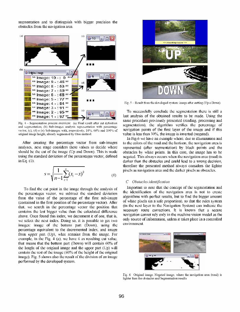
Fig. 4 - Segmentation process overview: (a) Final result after cut definitionand segmentation; (b) Sub-images analysis representation with percentagevector; (c), (d) e (e) Sub-images with, respectively, 10%, 60% and 100% oforiginal image height, already segmented by Otsu method.
After creating the percentage vector from sub-imagesanalyses, next stage considers these values to decide whereshould be the cut of the image (Up and Down). This is madeusing the standard deviation of the percentages vector, definedinEq. (1):
in
n- i,1 (1)
To find the cut point in the image through the analysis ofthe percentages vector, we subtract the standard deviationfrom the value of the percentage of the first sub-image(contained in the first position of the percentage vector). Afterthat, we search in the percentage vector the position thatcontains the last bigger value than the calculated differenceabove. Once found this index, we decrement it of one, that is,we select the next index. Doing so, it is possible to get twoimages: image of the bottom part (Down), using thepercentage equivalent to the decremented index, and imagefrom upper part (Up), what remains from the image. Forexample, in the Fig. 4 (a), we have 6 as resulting cut value,that means that the bottom part (Down) will contain 60% ofthe height of the original image and the upper part (Up) willcontain the rest of the image (400o of the height of the originalimage). Fig. 5 shows also the result of the division of an imageperformed by the developed system.
Fig. 5 - Result from the developed system: image after cutting (Up e Down)
To successfully conclude the segmentation there is still alast analysis of the obtained results to be made. Using thesame procedure previously presented (reading, processing andsegmentation), the algorithm verifies the percentage ofnavigation points of the first layer of the image and if thisvalue is less than 300O, the image is inverted (negated).
In Fig.6 we have an example where, due to illumination andto the colors of the road and the horizon, the navigation area isrepresented (after segmentation) by black points and theobstacles by white points. In this case, the image has to benegated. This always occurs when the navigation area (road) isdarker than the obstacles and could lead to a wrong decision,therefore the presented method always considers the lighterpixels as navigation area and the darker pixels as obstacles.
C. Obstacles identificationImportant to note that the concept of the segmentation and
the identification of the navigation area is not to createalgorithms with perfect results, but to find the bigger amountof white pixels (in a safe proportion), so that the rules system(in the next layer to the Navigation System) can indicate thenecessary route corrections. It is known that a securenavigation cannot rely only in the machine vision model as theonly source of information, unless it takes place in a controlledenvironment.
Fig. 6 -Original image, Negated image, where the navigation area (road) islighter than the obstacles and Segmentation results
96
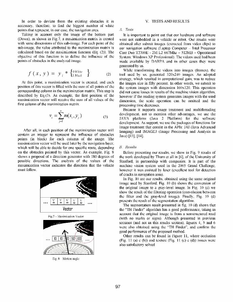
In order to deviate from the existing obstacles it isnecessary, therefore, to find the biggest number of whitepoints that represent, in our case, the navigation area.
Taking in account only the image of the bottom part(Down), as shown in Fig.7, a maximization matrix is createdwith same dimensions of this sub-image. For each point of thesub-image, the value attributed to the maximization matrix iscalculated based on the maximization function (Eq. (2)). Theobjective of this function is to define the influence of thepoints of obstacles in the analyzed image.
f (X ,y) = *{i Blackit } (2)
At this point, a maximization vector is created, and eachposition of this vector is filled with the sum of all points of thecorresponding column in the maximization matrix. This step isdescribed by Eq.(3). As example, the first position of themaximization vector will receive the sum of all values of thefirst column of the maximization matrix.
n
vi= m(Xi Ya) (3)j=l
After all, in each position of the maximization vector willcontain an integer to represent the influence of obstaclespoints (in black) for each column of the image. Themaximization vector will be used later by the navigation layer,which will be able to decide for one specific route, dependingon the obstacles pointed by this vector. As example, Fig. 8shows a proposal of a direction generator with 180 degrees ofpossible directions. The analysis of the values of themaximization vector indicates the direction that the vehiclemust follow.
VectorVector
V. TESTS AND RESULTS
A. TestsIt is important to point out that our hardware and software
were not embedded in a vehicle or robot. Our results wereobtained after submit images (extracted from video clips) toour navigation software (Laptop Computer - Intel ProcessorCore Duo T2300E - 2M L2 667Mhz - 512MB - OperationalSystem: Windows XP Professional). The videos used had beenmade available by DARPA and in other cases they weregenerated by us.
While transforming the videos into images (frames), thetool used by us, generated 320x240 images. An adoptedstrategy, which resulted in computational gain, was to reducethe images size in fifty percent. In other words, we submit tothe system images with dimension 160x120. This operationdid not cause losses in results of the machine vision algorithm,however if the reading system generates images with the useddimension, the scale operation can be omitted and theprocessing time decreases.
Because it supports image treatment and multithreadingdevelopment, not to mention other advantages, we use theJAVA platform (Java 2 Platform) for the softwaredevelopment. As support, we use the packages of functions forimage treatment that consist in the APIs: JAI (Java AdvancedImaging) and IMAGEJ (Image Processing and Analysis inJava) [13], [14].
B. ResultsBefore presenting our results, we show in Fig. 9 results of
the work developed by Thurn et all in [6], of the University ofStanford, in partnership with companies. It is part of themachine vision system used in the 2005 Grand Challenge,however it was assisted by laser (excellent tool for detectionof cracks in navigation area).
In Fig. 10 are our results, obtained using the same originalimage used by Stanford. Fig. 10 (b) shows the conversion ofthe original image to a gray-level image. In Fig. 10 (c) weshow the result ofthe filtering operation (convolution betweenthe filter and the gray-level image). Finally, Fig. 10 (d)presents the result of the segmentation algorithm.
The segmentation result presented in fig. 10 (d) shows thatthe "TH Finder" algorithm has a good performance, taking inaccount that the original image is from a nonstructured road(with no marks or signs). Although presented in previoussections (and not in this results section), figures 4, 5 and 6were also obtained using the "TH Finder", and confirm thegood performance of the proposed method.
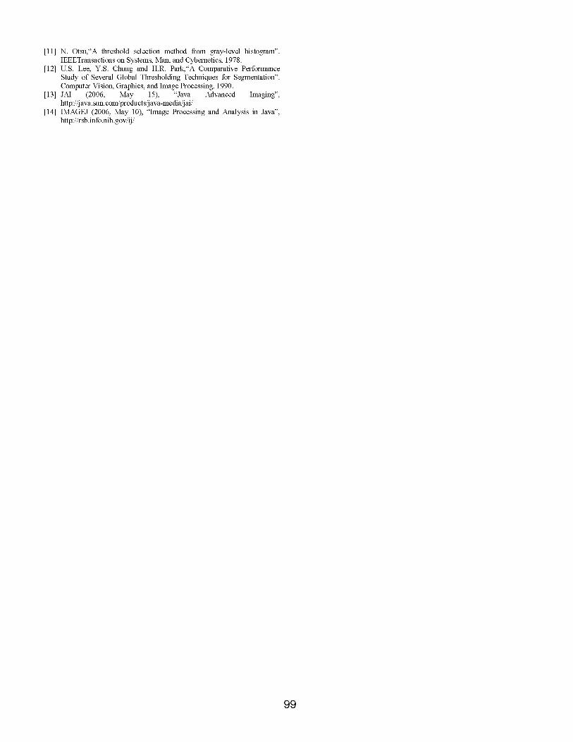
Other results can be found in Figure 11, where occlusion(Fig. 11 (a) e (b)) and texture (Fig. 11 (c) e (d)) issues werealso satisfactory solved.
Fig. 8 - Motion angle
97
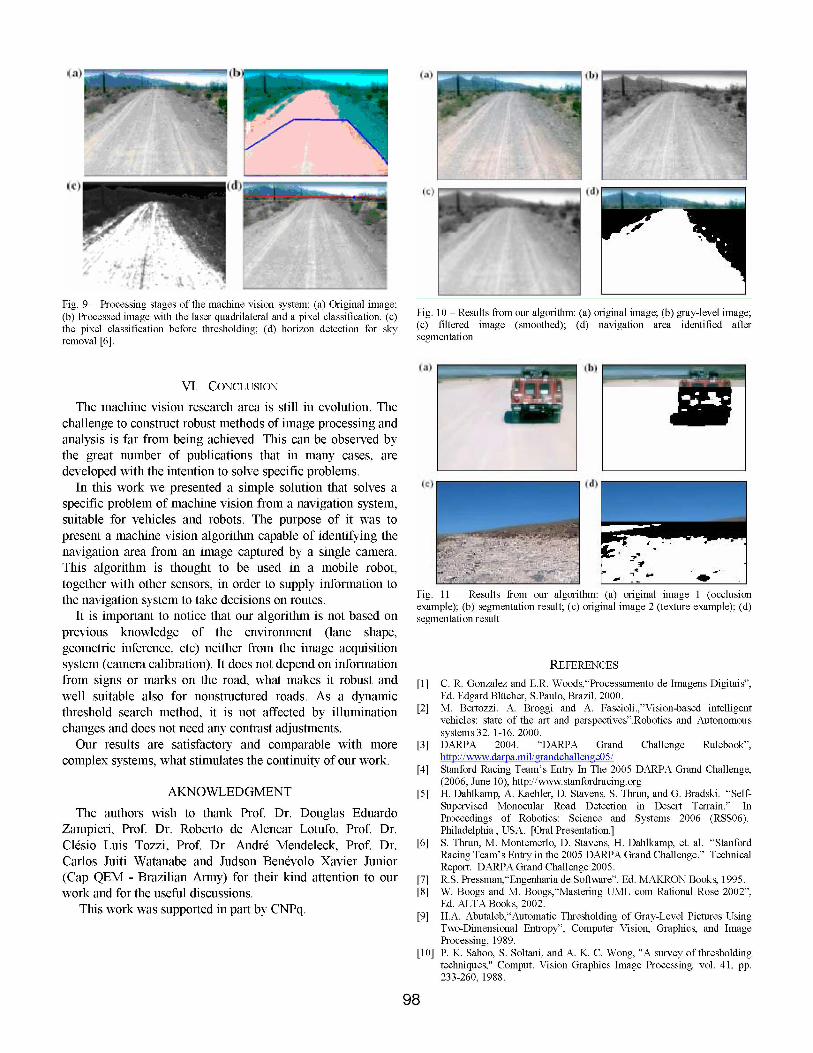
Fig. 9 - Processing stages of the machine vision system: (a) Original image;(b) Processed image with the laser quadrilateral and a pixel classification. (c)the pixel classification before thresholding; (d) horizon detection for skyremoval [6].
VI. CONCLUSIONThe machine vision research area is still in evolution. The
challenge to construct robust methods of image processing andanalysis is far from being achieved. This can be observed bythe great number of publications that in many cases, aredeveloped with the intention to solve specific problems.
In this work we presented a simple solution that solves aspecific problem of machine vision from a navigation system,suitable for vehicles and robots. The purpose of it was topresent a machine vision algorithm capable of identifying thenavigation area from an image captured by a single camera.This algorithm is thought to be used in a mobile robot,together with other sensors, in order to supply information tothe navigation system to take decisions on routes.
It is important to notice that our algorithm is not based onprevious knowledge of the environment (lane shape,geometric inference, etc) neither from the image acquisitionsystem (camera calibration). It does not depend on informationfrom signs or marks on the road, what makes it robust andwell suitable also for nonstructured roads. As a dynamicthreshold search method, it is not affected by illuminationchanges and does not need any contrast adjustments.Our results are satisfactory and comparable with more
complex systems, what stimulates the continuity of our work.
AKNOWLEDGMENTThe authors wish to thank Prof. Dr. Douglas Eduardo
Zampieri, Prof. Dr. Roberto de Alencar Lotufo, Prof. Dr.Clesio Luis Tozzi, Prof. Dr. Andre Mendeleck, Prof. Dr.Carlos Juiti Watanabe and Judson Benevolo Xavier Junior(Cap QEM - Brazilian Army) for their kind attention to ourwork and for the useful discussions.
This work was supported in part by CNPq.
Fig. 10 - Results from our algorithm: (a) original image; (b) gray-level image;(c) filtered image (smoothed); (d) navigation area identified aftersegmentation
Fig. 11 - Results from our algorithm: (a) original image 1 (occlusionexample); (b) segmentation result; (c) original image 2 (texture example); (d)segmentation result
REFERENCES[1] C. R. Gonzalez and E.R. Woods,"Processamento de Imagens Digitais",
Ed. Edgard Bltcher, S.Paulo, Brazil, 2000.[2] M. Bertozzi. A. Broggi and A. Fascioli.,"Vision-based intelligent
vehicles: state of the art and perspectives".Robotics and Autonomoussystems 32, 1-16, 2000.
[3] DARPA 2004. "DARPA Grand Challenge Rulebook",
[4] Stanford Racing Team's Entry In The 2005 DARPA Grand Challenge,(2006, June 10), http://www.stanfordracing.org
[5] H. Dahlkamp, A. Kaehler, D. Stavens, S. Thrun, and G. Bradski. "Self-Supervised Monocular Road Detection in Desert Terrain." InProceedings of Robotics: Science and Systems 2006 (RSS06).Philadelphia, USA. [Oral Presentation.]
[6] S. Thrun, M. Montemerlo, D. Stavens, H. Dahlkamp, et. al. "StanfordRacing Team's Entry in the 2005 DARPA Grand Challenge." TechnicalReport. DARPA Grand Challenge 2005.
[7] R.S. Pressman,"Engenharia de Software". Ed. MAKRON Books, 1995.[8] W. Boogs and M. Boogs,"Mastering UML com Rational Rose 2002",
Ed. ALTA Books, 2002.[9] H.A. Abutaleb,"Automatic Thresholding of Gray-Level Pictures Using
Two-Dimensional Entropy", Computer Vision, Graphics, and ImageProcessing, 1989.
[10] P. K. Sahoo, S. Soltani, and A. K. C. Wong, "A survey of thresholdingtechniques," Comput. Vision Graphics Image Processing, vol. 41, pp.233-260, 1988.
98
I a.l
[11] N. Otsu,"A threshold selection method from gray-level histogram".IEEETransactions on Systems, Man, and Cybernetics, 1978.
[12] U.S. Lee, Y.S. Chung and H.R. Park,"A Comparative PerformanceStudy of Several Global Thresholding Techniques for Segmentation".Computer Vision, Graphics, and Image Processing, 1990.
[13] JAI (2006, May 15), "Java Advanced Imaging",http:/java. sun. com/products/java-media/jai/
[14] IMAGEJ (2006, May 10), "Image Processing and Analysis in Java",http://rsb.info.nih.gov/ij/
99
Related Documents


