Master thesis in Computing science, 20 credits A Sequence Diagram Editor for BlueJ Matilda ¨ Ostling, <[email protected]> Department of Computing Science, Ume˚ a University 10th May 2004

Welcome message from author
This document is posted to help you gain knowledge. Please leave a comment to let me know what you think about it! Share it to your friends and learn new things together.
Transcript

Master thesis in Computing science, 20 credits
A Sequence DiagramEditor for BlueJ
Matilda Ostling, <[email protected]>
Department of Computing Science, Umea University
10th May 2004


Abstract
Today most programming courses for beginners use an object-oriented language.This has led to many new learning tools, theories and methods for teaching object-orientation. One such new tool is BlueJ which is developed to teach Java andobject-orientation for beginners. BlueJ does not have any support for drawing se-quence diagrams and this thesis describes the development of an editor for se-quence diagrams. The editor is developed as a plugin for BlueJ and designed tobe used by beginners. This paper describes the design and implementation of theeditor and it contains a user manual for the editor.
In this thesis it is also talked about UML diagrams in general and more specificabout sequence diagrams. The use of sequence diagrams in education of object-oriented thinking is described and advantages are pointed out. Object-orientededucation is discussed and different teaching methods are addressed.


Contents
1 Introduction 11.1 Background . . . . . . . . . . . . . . . . . . . . . . . . . . . . . 11.2 The Purpose of this Master’s Thesis . . . . . . . . . . . . . . . .21.3 Thesis Outline . . . . . . . . . . . . . . . . . . . . . . . . . . . . 2
2 UML 32.1 Diagrams in UML . . . . . . . . . . . . . . . . . . . . . . . . . . 4
2.1.1 Use Case Diagrams . . . . . . . . . . . . . . . . . . . . .42.1.2 Class Diagrams . . . . . . . . . . . . . . . . . . . . . . . 52.1.3 Object Diagrams . . . . . . . . . . . . . . . . . . . . . . 52.1.4 Interaction Diagrams . . . . . . . . . . . . . . . . . . . . 52.1.5 Behaviour Diagrams . . . . . . . . . . . . . . . . . . . . 72.1.6 Implementation Diagrams . . . . . . . . . . . . . . . . . 7
2.2 UML Diagrams in Education . . . . . . . . . . . . . . . . . . . . 72.2.1 Educational Benefits for Using a Subset of UML . . . . .8
2.3 Use Cases and their Scenarios . . . . . . . . . . . . . . . . . . .92.4 Sequence Diagrams . . . . . . . . . . . . . . . . . . . . . . . . .10
3 Teaching and Learning Software Development 153.1 Programming and Problem Solving . . . . . . . . . . . . . . . . .163.2 Coding and Design/Analysis . . . . . . . . . . . . . . . . . . . .173.3 Syntax and Semantics . . . . . . . . . . . . . . . . . . . . . . . .17
4 Teaching and Learning Object-Oriented Programming 194.1 Object-Oriented Programming vs. Procedural Programming . . .194.2 Different Teaching Approaches Using Java . . . . . . . . . . . . .204.3 Active Learning . . . . . . . . . . . . . . . . . . . . . . . . . . . 21
5 Sequence Diagrams in Education 25
6 A Sequence Diagram Editor for BlueJ 276.1 Requirements . . . . . . . . . . . . . . . . . . . . . . . . . . . .276.2 Design . . . . . . . . . . . . . . . . . . . . . . . . . . . . . . . .28
v

vi CONTENTS
6.2.1 The Graphical User Interface . . . . . . . . . . . . . . . .286.2.2 Return Messages . . . . . . . . . . . . . . . . . . . . . .306.2.3 Sequences . . . . . . . . . . . . . . . . . . . . . . . . . .316.2.4 Different Modes of the Editor . . . . . . . . . . . . . . .316.2.5 Creating a Plugin for BlueJ . . . . . . . . . . . . . . . . .316.2.6 File Management . . . . . . . . . . . . . . . . . . . . . .326.2.7 Automatic Consistency Check against BlueJ . . . . . . .346.2.8 Creation Messages . . . . . . . . . . . . . . . . . . . . .34
6.3 System Description . . . . . . . . . . . . . . . . . . . . . . . . .356.4 Future Work . . . . . . . . . . . . . . . . . . . . . . . . . . . . .38
7 Related Work 39
8 Summary and Conclusions 41
Acknowledgements 43
References 45
A User Manual 49A.1 Introduction . . . . . . . . . . . . . . . . . . . . . . . . . . . . . 50A.2 Installation of the Plugin . . . . . . . . . . . . . . . . . . . . . .50A.3 Starting the Plugin . . . . . . . . . . . . . . . . . . . . . . . . .50A.4 A Tutorial, Creation of a Sequence Diagram . . . . . . . . . . . .51A.5 Adding Components to a Sequence Diagram . . . . . . . . . . . .55
A.5.1 Adding an Actor . . . . . . . . . . . . . . . . . . . . . . 55A.5.2 Adding an Object . . . . . . . . . . . . . . . . . . . . . . 55A.5.3 Adding a Message . . . . . . . . . . . . . . . . . . . . .55A.5.4 Adding a Destroy Symbol . . . . . . . . . . . . . . . . .56A.5.5 Notes about the Sequence Diagram . . . . . . . . . . . .56A.5.6 Return Messages . . . . . . . . . . . . . . . . . . . . . .57A.5.7 Creation of a sequence . . . . . . . . . . . . . . . . . . .57
A.6 Save and Open a Sequence Diagram . . . . . . . . . . . . . . . .57A.7 Moving, Deleting and Editing . . . . . . . . . . . . . . . . . . . 58
A.7.1 Objects . . . . . . . . . . . . . . . . . . . . . . . . . . . 58A.7.2 Actors . . . . . . . . . . . . . . . . . . . . . . . . . . . . 58A.7.3 Messages . . . . . . . . . . . . . . . . . . . . . . . . . .59A.7.4 Destroy Symbol . . . . . . . . . . . . . . . . . . . . . . 59A.7.5 Lifeline . . . . . . . . . . . . . . . . . . . . . . . . . . . 59
A.8 Known Bugs . . . . . . . . . . . . . . . . . . . . . . . . . . . . 60

List of Figures
2.1 A use case diagram. . . . . . . . . . . . . . . . . . . . . . . . . .42.2 A class diagram. . . . . . . . . . . . . . . . . . . . . . . . . . . . 52.3 A sequence diagram. . . . . . . . . . . . . . . . . . . . . . . . .62.4 A collaboration diagram. . . . . . . . . . . . . . . . . . . . . . . 62.5 Notations for a sequence diagram. . . . . . . . . . . . . . . . . .112.6 More notations of a sequence diagram. . . . . . . . . . . . . . . .122.7 Object constraint language in a sequence diagram. . . . . . . . . .13
6.1 The window of the editor. . . . . . . . . . . . . . . . . . . . . . .286.2 The window of BlueJ. . . . . . . . . . . . . . . . . . . . . . . . .296.3 Description of the XML-file. . . . . . . . . . . . . . . . . . . . . 326.4 An example of a simple sequence diagram. . . . . . . . . . . . .336.5 A class diagram describing the system. . . . . . . . . . . . . . . .356.6 The state machine of a destroy symbol. . . . . . . . . . . . . . . .37
A.1 A view of the editor. . . . . . . . . . . . . . . . . . . . . . . . . 49A.2 Step one in the tutorial. . . . . . . . . . . . . . . . . . . . . . . .51A.3 Step two in the tutorial. . . . . . . . . . . . . . . . . . . . . . . .52A.4 Step three in the tutorial. . . . . . . . . . . . . . . . . . . . . . .53A.5 Step four in the tutorial. . . . . . . . . . . . . . . . . . . . . . . .54A.6 Class chooser. . . . . . . . . . . . . . . . . . . . . . . . . . . . .55A.7 Method chooser. . . . . . . . . . . . . . . . . . . . . . . . . . . .56A.8 Window for writing notes . . . . . . . . . . . . . . . . . . . . . . 56A.9 Filename chooser. . . . . . . . . . . . . . . . . . . . . . . . . . .57
vii


1Introduction
1.1 Background
Today object-orientation is widely used both in education and software devel-opment. Even though object-orientation has been taught for quite a long timenow, there exist many theories how to best teach object-oriented programmingand thinking to students. The widely usage of object-orientation in educationhave raised a lot of questions. Is it more natural for a student to think in anobject-oriented way then in a procedural way [Neubauer and Strong, 2002]? Is itharder to teach an object-oriented programming language then a procedural pro-gramming language? What is the correct way to teach object-orientation andwhich method should be used? There exist many opinions in this matter andsome “guidelines”, when teaching object-orientation with Java, have been devel-oped [Kolling and Rosenberg, 2001]. One often used technique is “active learning”which can shortly be described as having the students more active in the learningprocess [Smialek, 2000]. Some commonly used techniques are so called CRC ses-sions, Role play sessions and Use case sessions. They let the students act like dif-ferent objects in the system by playing scenarios where the system should achievedifferent tasks. Documenting these plays will help the students in designing theirsystems.
When teaching object-oriented programming languages to beginners, such asfor example Java, new tools are used. One example is BlueJ that is an IDE (In-tegrated Development Environment) for Java designed to be used by beginners,seewww.bluej.org . It is designed to help students understand the foundationsof object-oriented programming and is not meant to be used by experienced pro-grammers. When teaching object-orientation today sequence diagrams are oftenused. They have shown to be very beneficial for beginners to object-orientationand are good since they can for example be helpful in the design phase, clarify theprogram flow of the system and be used in the test phase [Fowler and Scott, 1997,Kutar et al., 2002].
1
2 Chapter 1. Introduction
1.2 The Purpose of this Master’s Thesis
BlueJ does not have any support for drawing sequence diagrams and this paper willdescribe the development of an editor for sequence diagrams designed as a pluginfor BlueJ. The editor will be connected to projects1 in BlueJ and help the studentsdraw sequence diagrams describing their implemented classes and methods. Theeditor is designed just as BlueJ to be used by beginners and it does not provide allpossible notations for a sequence diagram but only the most basic parts. The editorhas been developed with the same philosophy as BlueJ, to “keep it simple” andmake it easy to use and understand.
1.3 Thesis Outline
In the first chapter the UML and its different diagrams are shortly described. Laterin this chapter use cases, scenarios and sequence diagrams are described in moredetail and the advantages of using sequence diagrams in education are distin-guished.
In chapter three teaching and learning software development is discussed ingeneral and in the next chapter, chapter four, teaching and learning object-orientedprogramming is discussed. Different methods are illustrated and active learning isdescribed in more detail. In chapter five the use of sequence diagrams in educationis talked about and advantages and disadvantages are pointed out.
Next chapter, chapter six, describes the design and development of the editorfor sequence diagrams. The editor is described and the design choices are ex-plained. The system of the editor is also shortly explained and shown. After this achapter follows containing a short summary and conclusions of this work.
At the end of this thesis an appendix is attached containing an user manual forthe editor. The user manual helps the user to install and use the editor.
1In BlueJ implemented classes belonging to the same system are saved together as projects.

2UML
The development of the Unified Modeling Language (UML) began in October of1994 and is an evolution from Booch method by Grady Booch, OMT (Object Mod-eling Technique) by James Rumbaugh, OOSE (Object-Oriented Software Engi-neering) by Ivar Jacobson and other object-oriented methods [Mrozek et al., 2002].In October of 1995 UML 0.8 (then called the Unified Method) came. UML 1.1 wasreleased in September of 1997 and the development is still in progress. UML 2.0was released in 2003 and newer versions are expected soon [Bjorkander, 2003].
UML is a visual modeling language consisting of nine diagrams. A model of asoftware system can be explained as an abstract representation of the system. Thesenine diagrams in UML are used to visualize, specify, construct, and document thedifferent components of a software system before the implementation. UML isused to make “blueprints” of a software system, this is necessary within big projectsto get an overview of the system. UML has a tight mapping to object-oriented lan-guages and is best suited for designing systems of this kind but UML can also beused advantageous with other programming languages [Rumbaugh et al., 2001].Though UML is intentionally process independent the authors of UML advocatethat UML is used in use-case-driven, architecture centric, iterative and incremen-tal development processes [Rumbaugh et al., 1997b]. Two examples of such pro-cesses that are used for development in software engineering are the Unified Pro-cess and RUP (Rational Unified Process) [Phillips, 1998].
Static view Dynamic view
Class diagrams State-chart diagramsObject diagrams Activity diagramsUse case diagrams Sequence diagramsComponent diagrams Collaboration diagramsDeployment diagrams
Table 2.1. The nine diagrams in UML version 1.5 belonging to the static view and thedynamic view, respectively.
3

4 Chapter 2. UML
2.1 Diagrams in UML
The UML is composed of nine different diagrams. Which diagram to use de-pends upon each special situation and the types of problems being solved. Usuallythe different diagrams are divided into two groups, static and dynamic models,see table 2.1. The static models, also called the structural models, underline thestructures of different objects in a system, including their classes, interfaces, at-tributes and relations between them. The diagrams belonging to the static view areclass diagrams, object diagrams, use-case diagrams, and implementation diagrams(component and deployment diagrams). The dynamic models, also called the be-havioural models, emphasize the behaviour of different objects in a system, includ-ing their methods, interactions, collaborations, and different states. The diagramsincluded in this view are behaviour diagrams (state-chart and activity diagrams)and interaction diagrams (sequence and collaboration diagrams).
The following sections will briefly describe the different diagrams in UML andin what situations to use each diagram.
2.1.1 Use Case Diagrams
Use case diagrams describewhata system does and are closely connected to sce-narios. Scenarios will be described in section 2.3. They can be thought of as asummary of scenarios for a single task or goal. Use case diagrams are best whendevelopers are communicating with clients since they are relatively easy to under-stand and relate to. Use case diagrams are also useful when designing the system,when the requirements are made, and for generating different test cases for use inthe testing phase [Booch et al., 1999].
Patient
Schedular
Cancel Appointment
Make Appointment
Doctor
Request Medication
Figure 2.1. An example of an use case diagram.

2.1. Diagrams in UML 5
2.1.2 Class Diagrams
To get an overview of a system, its classes and the relationships between them, aclass diagram is used. The relationship among the classes can be several differ-ent kinds. The three most used relationships are association, generalization, andaggregation. An association between two classes is a labelled relationship. A gen-eralization is a hierarchical relationship between two classes, meaning that oneclass is the parent of the other class, as in an inheritance hierarchy. An aggrega-tion between two classes (also called a dependency) is a relationship meaning thatone class depends on another in some way that if changing one class may lead tohave to change the other class too. Class diagrams are static in the way that theydescribe what parts interact and not what happens when they interact with eachother [Booch et al., 1999, LeBlanc and Stiller, 2000].
Figure 2.2. An example of a class diagram.
2.1.3 Object Diagrams
The object diagram is very similar to the class diagram except that they show in-stances (objects) instead of classes. The object diagram models a set of objectsand their relationship during a system snapshot. An object diagram is very usefulwhen, for example, explaining complicated relationships within a smaller part of asystem [LeBlanc and Stiller, 2000].
2.1.4 Interaction Diagrams
Interaction diagrams describe dynamic aspects of a system and there are two kindof interaction diagrams, sequence diagrams and collaboration diagrams.

6 Chapter 2. UML
A sequence diagram explains how operations are performed, describing differ-ent scenarios. They show how different objects work together and what messages(method calls) are sent between them. A sequence diagram shows time-orderingbetween messages and the messages are organized chronological. A sequence dia-gram is shown in figure 2.3.
MessageA
MessageB
MessageC
blueObject:ClassBlueredObject:ClassRed
Figure 2.3. An example of a sequence diagram.
Collaboration diagrams contain the same information as sequence diagramsbut they concentrate on the role of the objects, the relationship between the ob-jects, and the communication between them. Instead of having an axis showing theordering in time between the messages each message has a sequence number. Acollaboration diagram is shown in figure 2.4.
1.1: MessageA1.3: MessageC
1.2: MessageB
redObject:ClassRed blueObject:ClassBlue
Figure 2.4. Example of a collaboration diagram.
Both collaboration and sequence diagrams are best to use when different sce-narios are being described. The collaboration diagram emphasizes “who-is-talking-to-whom” and the time-ordering of the messages gets a little clouded. The se-quence diagram on the contrary accentuates the time-ordering of the messagesthough here the-who-is-talking-to-whom situation gets obscured [Software, 2001].Sequence diagrams and scenarios will be described in section 2.3 and in sec-tion 2.4.

2.2. UML Diagrams in Education 7
2.1.5 Behaviour Diagrams
Objects can have different behaviour and states depending on their current actionsor conditions. There are two diagrams to describe the behaviour and states of anobject, statechart diagrams and activity diagrams.
A statechart diagram displays the possible states for an object and the transi-tions that will change the state of the object. The activity diagram instead focuseson the activities in a special process and the flow of activities. It shows how thedifferent activities depend on each other. Even though the two different types ofbehavioural diagrams are closely related an activity diagram can be described asa “flowchart”, showing the flow of activities in a process, the statechart diagramconcentrates on the object and its different states in a process and what causes thechange in state for the object.
2.1.6 Implementation Diagrams
There are two kinds of implementation diagrams in UML, the component diagramand the deployment diagram. These diagrams display the view of implementationand the run-time implementation structure [Booch et al., 1999]. The componentdiagram describes the organization of physical software components, includingsource code, run-time code, and executables. The deployment diagram depicts thephysical resources in a system, including nodes, components, and connections.
2.2 UML Diagrams in Education
The UML with its nine different diagrams is extremely large and offers many no-tational possibilities. When students new to object-orientation and programmingare trying to learn and use UML they can easily be confused and find it difficult touse UML. It easily happens that they miss the big picture which is very importantfor understanding the goals and processes of software engineering. Though UMLis very complex with a lot of rules for syntax and semantics the most importantcore of the language is quite easy to learn and understand which is pointed out byLeBlanc and Stiller [LeBlanc and Stiller, 2000].
When students start to use UML they only need to use a subset of the ninediagrams in UML or otherwise the students would be overwhelmed with all thepossible notations. The subset has to offer the student enough of notational possi-bilities so he or she can model a software system without getting confused. Whichsubset of UML to use in education is under discussion and there are many pro-posals of suitable subsets of the UML. The class diagram, the sequence diagramand/or the collaboration diagram appear to be the most used diagrams in education.

8 Chapter 2. UML
These diagrams would be enough for beginners in programming and make it possi-ble for the students to document the software systems without finding it confusingand too hard. Others wish to include more diagrams in the subset of UML forbeginners. For example LeBlanc and Stiller [LeBlanc and Stiller, 2000] suggesta subset containing the use-case diagram, the class diagram, the object diagram,the collaboration diagram and the sequence diagram. The activity diagram and thestatechart diagram have not been mentioned but they are also used when tutoringbeginners. Since object diagrams are quite similar to class diagrams a commonopinion is that they are not very important for beginners to UML. Sequence dia-grams and collaboration diagrams contain and display almost the same informationso it may be a good idea to use only one of these diagrams. According to differentempirical studies sequence diagrams are often shown to be easier to learn and readthan collaboration diagrams. Kutar, Britton and Barker [Kutar et al., 2002] haveperformed a study that showes that sequence diagrams are better than collabora-tion diagrams. The study performed both an empirical and a cognitive study of thetwo diagrams. The result of the cognitive study was that sequence diagrams areeasier to read and understand then collaboration diagrams. The empirical study didnot support this theory as much as expected, but it did not reject it neither. The con-clusion of the study was that sequence diagrams are often better than collaborationdiagrams though this must be better established with further studies. Even thoughthis study shows that sequence diagrams are to prefer there are certainly a numberof occasions when a collaboration diagram is better then a sequence diagram.
2.2.1 Educational Benefits for Using a Subset of UML
A class diagram is useful in the way that it models the composition of classes in asystem. Showing the different relationships between the classes and the elementsbeing part of each class. A class diagram gives a static view of the system, thougha system can have many class diagrams showing different structural aspects of thesystem. For students having difficulties understanding inheritance (which is a basicconcept in object-orientation) between classes a class diagram can help. It alsoshows how the classes depend upon each other and how the system is composed.
An object diagram reminds very much of a class diagram and has the sameadvantages. The big difference is that instead of showing how different classesdepend upon each other an object diagram shows instances of classes, objects.An object diagram contains values of different attributes making it possible forstudents to understand and see the relationships between objects at a given time.
Use case diagrams are used to show how the system interacts with a user andare commonly used in the design phase of a system. A use case diagram is usefulfor students when designing the new system/program and modeling the behaviour
2.3. Use Cases and their Scenarios 9
of the system towards a user. This kind of diagram is good since it hides much ofthe functionality of the system and only describes what the system should do. Thestudents can then concentrate of the behaviour of the system instead of thinkingabout how the system should achieve certain tasks.
The interaction diagrams, collaboration diagrams and sequence diagrams arequite similar and display almost the same information. They show the interactionbetween objects in a system and describe the communication between them. Thesediagrams have shown to be very useful for students and quite easy and intuitive tolearn and understand. Both collaboration and sequence diagrams can really help astudent to see the program flow of the system and help them understand how theobjects work together. Often it can be very hard in an object-oriented system to findthe flow of program, especially for beginners in the area, since there is seldom anobvious program flow in an object-oriented system as it is for example in a systemwritten in a procedural language [Fowler and Scott, 1997].
Sequence diagrams also have a very prominent role in teaching object-orienta-tion today together with active learning, see section 4.3. Active learning can shortlybe described as including the students more in the teaching/learning process andmaking them more active in their search for knowledge. Many investigations alsoshow that sequence diagrams are found to be very useful both when designing anew system and also when trying to understand an already existing system. Se-quence diagrams have shown to be appreciated both by experienced programmersand by novices. Though collaboration and sequence diagrams almost contain thesame information, sequence diagrams more clearly show the program flow andhelps the student understand the system. A sequence diagram is also often quitestructured and it is easy to read and follow the program flow. A collaboration dia-gram can easily become a little indistinct if it gets too big and complex includingmany objects and messages. This makes the messages cross each other and makesit hard to arrange the objects in a structured way, leading to a diagram being diffi-cult to interpret. Sequence diagrams and their use in education together with activelearning will be further described in chapter 5.
2.3 Use Cases and their Scenarios
Use cases are used to describe sequence of events and to show how the system issupposed to interact with an actor (a user of the system). A use case is often just aplain text documentation that can be obtained from, for example, the requirementsdocument. A use case is created for every major functionality of the system. Usecases are very useful in the design-phase since they describewhat a system doeswithout having to sayhow the system should achieve a certain task and how to

10 Chapter 2. UML
implement it [LeBlanc and Stiller, 2000].
Scenarios can be used in many situations, for example in the analysis of therequirements, in the software design, or in the implementation. The first two men-tioned are probably the most important and mostly used areas. A scenario is usedto describe a system’s behaviour in a specific situation and can also be describedas an instance of a use case. It is created from a use case by looking at every pos-sible outcome and creating a scenario for each possibility. It is important to notonly create scenarios for the normal system but also to show what will happen ifan error occurs or if the system breaks down. Scenarios can be documented just inplain text or sometimes using different states or logic. From the different scenariosresulting from the use cases, sequence diagrams can be drawn. These sequence di-agrams are often very useful in e.g. the design-phase of the software developmentand the documentation of it.
2.4 Sequence Diagrams
A sequence diagram shows the interaction between objects in time. The diagramdisplays the communication, i.e. the objects participating in the interaction and theactual messages sent between them. The sequence diagram focuses on the time-ordering between the messages, compared to the collaboration diagram that focuseson communication between the objects and the relationship between them. The re-lationship between objects is not shown at all in a sequence diagram. Sequence dia-grams are used throughout the design phase in the development process to show thedifferent scenarios in the system. They are suitable in real-time specifications andfor complex scenarios. Sequence diagrams are used to model use case scenarios,protocols in a framework, subsystems, classes, and method logic [Miller, 2001b].
Or as Fowler [Fowler and Scott, 1997] explain the role of sequence diagrams:
“One of the hardest things to understand in an object-oriented pro-gram is the overall flow of control. A good design has lots of smallmethods in different classes, and at times it can be tricky to figure outthe overall sequence of behaviour. You can end up looking at the codetrying to find the program. This is particular true for those new toobjects. Sequence diagrams help you to see that sequence.”
The sequence diagram is very attractive since it permits a lot of useful infor-mation to be shown at the same time. One thing is that the objects interactingwith each other (in the described scenarios) can be ordered in such a way thatthe interaction is easier to understand and follow. Another good thing with se-quence diagrams is that the lifeline of the object can point out the activity of the

2.4. Sequence Diagrams 11
object in isolation. Last and maybe most important is the way that sequence dia-grams show the sequence of execution and the distribution of execution betweenobjects [Fowler and Scott, 1997].
Object A
Actor B
Figure 2.5. The different notations in a sequence diagram. First the notation for an objectis shown, then an actor. In the middle is a lifeline for an object and then an activation forit. Last is the notation for a message sent between the objects.
A sequence diagram has two dimensions, time which is represented by thevertical dimension and different objects and actors that are represented by the hor-izontal dimension. In most cases time proceeds down the page though if desiredthe dimension may be reversed. The ordering among objects in the horizontal di-mension is of no significance and arbitrary. But often the objects are ordered insuch a way that the call arrows (messages) are arranged to point in the same direc-tion (to the right) but in some cases this is not possible. Each object has a verticaldashed line which is called the lifeline of the object. The existence of the object isrepresented by the lifeline at a particular time [Rumbaugh et al., 1997a]. The life-line can show whether the object is being created or destroyed during the shownscenario and when and for how long the object is active. The activity of the objectis shown as a tall thin rectangle which starts at the initiation of the activation andends when the object is not active anymore. If the object is being destroyed this ismarked with a big “X” and the message destroying the object points at the “X” andthe lifeline is ended at this point. If the object is created this is shown by letting themessage creating the object point to the object symbol. This is shown in figure 2.6.An object that exists throughout the whole scenario has its lifeline from the top tothe bottom of the diagram.
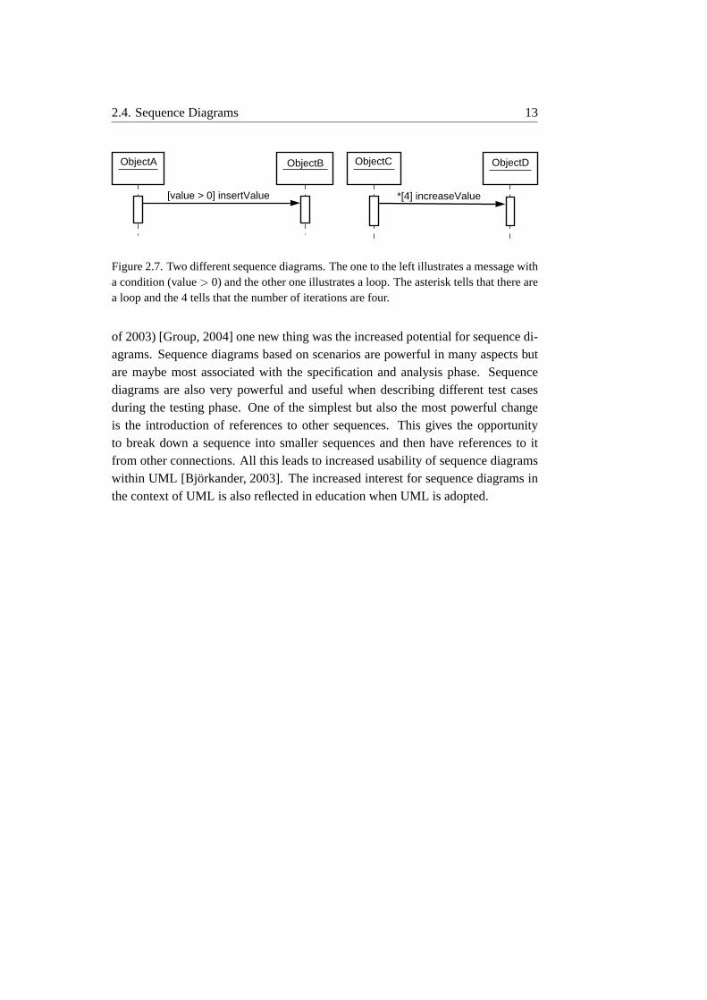
A sequence diagram can also display conditions, branches and loops, see fig-ure 2.7. A condition is shown by putting the condition (e.g. an if-statement) en-closed in square brackets to the left of the message name. To symbolize a loop anasterisk (*) is used before the name of the message. If the number of iterations areknown this number can be put in square brackets after the asterisk, though this isvery seldom the case [Miller, 2001a]. To present a branch several arrows can startat a single point each with a guard condition. If the object sends a message to itselfthe call arrow just points back to this object, making an U-turn, see figure 2.6.
To express conditions, branches and loops in a sequence diagram (or another

12 Chapter 2. UML
updateID
idNumber
destroy
new secondObject() secondObject:Second
firstObject:First
Figure 2.6. The notation for creation of an object and the notation for destroying an object.The secondObject is first created be the firstObject and then after sending a message backto the firstObject the secondObject is destroyed by the firstObject.
UML diagram) the Object Constraint Language (OCL) is used. OCL is part of theUML and it is a formal language used to express constraints. It is not a program-ming language but a specification language that uses simple logic for expressingdifferent constraints [Rumbaugh et al., 2001].OCL can be used for different intentions [Rumbaugh et al., 2001]:
• To specify invariants on classes and types in the class model.
• To specify type invariant for Stereotypes.
• To describe pre- and post conditions on operations and methods.
• As a navigation language.
• To describe guards.
• To specify constraints on operations.
OCL is often used to show constraints for a message in a sequence diagram.The given constraint says that it should only be executed if a special condition isfulfilled and OCL is used to express this condition. OCL is a typed language soeach expression must have a type. A String can not be compared to an Integer inOCL and there is a set of predefined types in OCL that can be used when writingexpressions using OCL. There are also predefined operators, keywords and the likein OCL [Rumbaugh et al., 2001].
In later versions of UML sequence diagrams have come to have a more promi-nent meaning. In the specification for UML 2.0 that was recently released (summer
2.4. Sequence Diagrams 13
ObjectA ObjectDObjectCObjectB
[value > 0] insertValue *[4] increaseValue
Figure 2.7. Two different sequence diagrams. The one to the left illustrates a message witha condition (value> 0) and the other one illustrates a loop. The asterisk tells that there area loop and the 4 tells that the number of iterations are four.
of 2003) [Group, 2004] one new thing was the increased potential for sequence di-agrams. Sequence diagrams based on scenarios are powerful in many aspects butare maybe most associated with the specification and analysis phase. Sequencediagrams are also very powerful and useful when describing different test casesduring the testing phase. One of the simplest but also the most powerful changeis the introduction of references to other sequences. This gives the opportunityto break down a sequence into smaller sequences and then have references to itfrom other connections. All this leads to increased usability of sequence diagramswithin UML [Bj orkander, 2003]. The increased interest for sequence diagrams inthe context of UML is also reflected in education when UML is adopted.


3Teaching and Learning SoftwareDevelopment
When teaching software development there are some concepts that are essential andit is important for the teacher to explain and clarify these concepts for the student.Most people think that software development is just about sitting in front of thecomputer and writing code. They do not understand the concepts design, analysis,problem solving etc. It is very important that a student new to programming learnsand understands these concepts and realizes the meaning of them. Many studentsfind it less interesting with design and does not fully understand the importance ofdesign. They just want to take the problem and write the code for it without makingany design or thinking about the best way to solve the problem. In the beginningthis can work but when the problems get more complicated and the systems toimplement get more complex this method will fail. So it is very important thatthe teacher lets the students realize the importance of design and have them seethe positive side of it. Many authors have agreed that the most important thingwhen teaching/learning programming are the issues of problem solving, designand expressing a solution or design as a program [Robins et al., 2003].
Learning to program is not easy and it involves getting complex new knowl-edge and practical skills. Du Boulay [du Boulay, 1989] describes five sources ofdifficulty that must be overcome. These five domains are overlapping and some-times all these new things can come as a “shock” for the student.These domains are:
General orientation - What programs are for and what can be done with them.Understanding that programs are usually written for a purpose, with respectto some task, problem or specification.
The notional machine - A model of the computer as it relates to executing pro-grams. Getting an overview of the computer, how it works and “how” theprograms implemented are executed.
15

16 Chapter 3. Teaching and Learning Software Development
Notation - The syntax and semantics of a particular programming language. Learn-ing to understand and use the new programming language. Learn how towrite different statements and how to combine them into a program solvinga given task.
Structures - How we learn new things according to special schemas and/or plans.Learning about these things can simplify the learning and understanding ofe.g. a new programming language.
Pragmatics - Meaning to develop and exercise the skills of planning, developing,testing, debugging and so on.
3.1 Programming and Problem Solving
One common misunderstanding with programming and software developing is theimportance of good problem solving. A good programmer is not just an expertat writing code but is also (often) a good problem solver which results in wellwritten and effective implementations for different problems. A given problemcan of course be solved and implemented in a number of ways and here the prob-lem solving phase is crucial. Solving different problems and finding solutions aresomething that can be exercised. The hard part is often to see the whole pictureof the problem, understand it and find a good solution to the problem. One goodstart is to split the problem into smaller parts. So instead of having onebig prob-lem there are manysmallerproblems. Then these small problems can be solvedand by combining their solutions the big problem can be solved. This division ofa problem into smaller parts is something that must be practiced. By doing thisrepeatedly a person can learn good ways to divide a problem and be able to seecommon patterns and often old solutions can be reused. Today many courses inprogramming for beginners use problem solving based teaching, also called prob-lem based learning. Though there are many people positive to this approach thereare also people meaning that the biggest difficulty for a novice programmer is to ex-press solved problems using a programming language [Robins et al., 2003]. Thesepeople mean that problem solving is of course important, but the student also hasto learn the programming language, how to use it, and how to write programs forthe solved problems.
3.2. Coding and Design/Analysis 17
3.2 Coding and Design/Analysis
When the problem has been analysed and solved the design phase of the pro-gram/system can start. Before starting with the implementation the system hasto be designed. When students new to programming learn and hear about designthey often find it unnecessary and do not realize the importance of design. Becausethe programs they write in the beginning are so small it can be hard for them tosee how significant the design is. But it is really important that it is pointed out forthem why design is so crucial. Trying to explain how difficult (impossible) it wouldbe to create a bigger system without any design is very important and also to showthem examples of bigger systems. Since most programming courses for beginnerstoday use an object-oriented language the significance of design grows since designis quite fundamental in object-orientation. To express the design UML-diagramsare often used. Since the UML is composed of nine different diagrams it is rec-ommended that only a subset of the diagrams is used so the student does not findit too overwhelming. Design is just as problem solving something that must bepracticed and exercised. There are many different methods to teach design andmany are connected to object-oriented design. This will be further discussed laterin section 4.3.
3.3 Syntax and Semantics
When learning a new (programming) language the student first has to learn whateverything means and how it is written. This is when syntax and semantics are thecrucial concepts. Shortly the syntax of a language can be described as how the dif-ferent expressions, statements and program units are written. The semantics of thelanguage can be described as the meaning of those expressions, statements and pro-gram units. Syntax and semantics are closely related and it is often found easier tounderstand/explain syntax then semantics. As Robert W. Sebesta [Sebesta, 1999]says this is partly because a concise and universally accepted notation is availablefor syntax description but yet there is none developed for semantics.
To clarify the difference between semantics and syntax lets take an if-statementwritten in the syntax of the programming language C.
if (< expr >) < statement >
How we write this statement form is controlled by the syntax and this is the correctsyntax for an if-statement written in C. The semantics of this statement form is thatif the expression (the current value of it) is true then the statement will be executed.
Many different studies have shown that novice programmers who know the

18 Chapter 3. Teaching and Learning Software Development
syntax and semantics of individual statements in a programming language oftenfind it very hard to combine these statements into a program. They have solvedthe problem (by hand) but they can not write an equivalent computer program forthe solution [Robins et al., 2003]. So learning the syntax and sematics of a pro-gramming language does not mean that the student will be able to write programsusing the given language. First he or she has to learn how to “translate” the solvedproblem into code by combining different statements.

4Teaching and LearningObject-Oriented Programming
4.1 Object-Oriented Programming vs.Procedural Programming
Today most programming courses for beginners use an object-oriented languageinstead of a procedural language. One of the main reason for the change in pro-gramming language is that the proponents of object-orientation are claiming thatobject-oriented thinking is more natural than procedural thinking. Neubauer andStrong [Neubauer and Strong, 2002] write about the theory that object-orientationis more natural and base this theory on the idea that the world we live in andexperience is filled with things, or objects, which have both attributes and be-haviours. Though this theory would lead to beginners preferring object-orientedthinking some people point out that beginners prefer the procedural way. Neubauerand Strong write that the explanation for this could be that students from the firstday in school learn mathematics in a procedural way looking at procedural pro-cesses applied to data. Object-orientation has a drawback as many students seeit, it includes a lot of design and abstraction. Most students are not really in-terested in design and think of programming as equal to writing code. Anotherdisadvantage with object-orientation is that many find it more difficult to debugand correct an object-oriented system than a system written in a procedural lan-guage [Neubauer and Strong, 2002].
Though there are many pros and cons about object-orientation almost all uni-versities today use an object-oriented language in the first programming courseand the ones not doing so are planning to. This change in programming languagehas led to discussions about how to best teach object-oriented programming andwhich pedagogy is the best. Some mean that since object-orientation is quite newin education there are (yet) no good software tools and teaching support materials.This has led to teachers finding it more difficult to teach object-oriented thinking
19

20 Chapter 4. Teaching and Learning Object-Oriented Programming
than the procedural approach [Kolling and Rosenberg, 2001, Lewis, 2000]. Con-sidering the opinion that it is harder for students to think in an object-oriented way,rather than in a procedural way, the strategies for teaching object-orientation reallyhas to help the students to think in an object-oriented way. The students have tolearn to think and program with objects [Neubauer and Strong, 2002]. Since allthis is rather new there are several different theories and strategies about how tobest teach object-oriented thinking and it is hard to say which strategy is the best.
Today most programming courses for beginners use Java as the programminglanguage. Next section 4.2 describes different teaching approaches for object-orientation with Java as the programming language.
4.2 Different Teaching Approaches Using Java
There are some guidelines that are often mentioned in many articles about teach-ing object-oriented programming and thinking to beginners with Java as the pro-gramming language. The most common approaches are“Objects first” and“Ob-jects early” which point out the importance of that students first of all get the un-derstanding of objects when learning object-oriented programming and thinking.Though there is no scientific evidence, or very little, to support this theory mostteachers and textbooks today are following this approach and start with objectsearly [Kolling and Rosenberg, 2001]. Ralph Westfall [Westfall, 2001] on the otherhand says that this is not the case and one of his explanations is that many teachershave a background from programming with procedural languages. Another argu-ment in the discussion is the use of “Hello world”-programs for beginners. Manyclaim that this is a very bad example to start with and that it is not object-oriented atall [Kolling and Rosenberg, 2001] when others mean that if it is correctly used andexplained it is a good example [Lewis, 2000]. Ralph Westfall [Westfall, 2001] saysthat the “Hello World”-program must be rewritten to be object-oriented and givesan example of this. He says that in most books for teaching Java the following codeis presented:
class HelloWorld {
public static void main(String[] args) {
System.out.println(’’hello, world’’);
}
}
He means that this code will only confuse the students and not teach them anythingabout object-orientation. Ralph Westfall says that the code has to be rewritten toinclude a user-created object. The result would then be:

4.3. Active Learning 21
class HelloWorld {
public static void printHello() {
System.out.println(’’hello, world’’);
}
}
class UseHello {
public static void main(String[] args) {
HelloWorld myHello = new HelloWorld();
myHello.printHello();
}
}
The main method in Java is also considered to be a problem by many teach-ers since its only purpose is to connect the application to the operating system.The code does not naturally relate with any classes or objects and it does not im-plement an operation on an object [Kolling and Rosenberg, 2001]. Another thingwith Java is its support to deal with input and output which is huge and complexand can lead to difficulties for beginners. A proposal to solve this is that the teach-ers provide students with classes for I/O that encapsulate the complexities in Java.Another approach is that the standard I/O is just avoided until the students are ableto understand and use it [Lewis, 2000]. There are more guidelines for teachingobject-orientation that often come up. One is that the students in the first stagedo not start with a blank screen but instead make changes to already existing codeand see what the result of the changes are. It is also recommended that studentsread code to get a sense of well written programs and learn about good style andidioms [Kolling and Rosenberg, 2001]. It is really not easy for a student to writegood code if he or she never got the opportunity to read well written and structuredcode.
4.3 Active Learning
To fulfil all, or at least some, of the guidelines mentioned in section 4.2 whenteaching object-oriented thinking some newer approaches have been adopted. Onewidely used approach isactive learning. Active learning means that the studentinstead of just receiving new knowledge from the teacher instead gets a problemand solve it, often with some guidance from the teacher. This type of educationforces the learner to find and to use new knowledge to solve the given problem.This type of education is also called learner-centered education since it involvesthe students more in the learning process and make them more active. It seems that

22 Chapter 4. Teaching and Learning Object-Oriented Programming
people learn best when absorbed in the subject and actively participating in the pro-cess towards their own learning and understanding [Harley et al., 1998]. Thoughthis technique with active learning seems to give the learners good understandingquickly it cannot be backed with any statistical data [Smialek, 2000]. It has alsobeen shown that if students work in pairs or in groups better results are achieved.This depends on two things. The first thing is that students working in a group cansolve more complex and interesting problems than a student working alone leadingto more active and engaged students. The second thing is that students in a grouphave to discuss for example different designs and argue with each other and this isthe kind of reflection that leads to learning [Harley et al., 1998].
One often used technique is pair-programming. This technique is used bothfor beginners to programming and for experienced programmers. The proponentsof pair-programming mean that by always being two persons common and “un-necessary” errors can easily be avoided, the solutions often get better and the twoprogrammers can switch places to avoid having a person doing the same thing fora long time [Jensen, 2003]. When beginners use pair-programming more com-plex and interesting problems can be solved and the student not typing can checkfor errors in the code which are often easier to discover when “sitting on theside” [Williams and Kessler, 2003]. It has also shown that when students work-ing together the process of learning a new programming language is significantlyfaster then for a student working alone [Williams and Kessler, 2003].
According to these new approaches for education of object-oriented thinkingthere are some basic elements that are widely used. Two of them areuse casesandCRC cards. Using these methods together with the philosophy of active learningthe best result is achieved when teaching object-oriented thinking [Smialek, 2000].
Use case session- In a use case session the different use cases of the system aremodelled and for each use case when it is possible a number of scenariosare developed. The participants of the session, which the students are, writedown the scenarios using a very elementary grammar. Sometimes these usecase sessions can be formed like interviews where somebody plays the roleof the user, somebody the role of the analysts and the rest of the group reviewthe session by documenting the scenario. This documentation is for exampledone with a sequence diagram or a simplification of one [Smialek, 2000].
CRC sessions- CRC cards characterise objects by Class name, Responsibilities,and Collaborators and are widely used for teaching novice programmers theconcept of object-oriented thinking and design [Beck, 1989]. Often the pro-cess starts with identifying the classes in the future system and making aCRC-card for each class. Then the responsibilities and collaborators of theobject are added on the cards. Now the students can use the CRC-cards to
4.3. Active Learning 23
illustrate different scenarios in the future system and document these scenar-ios. This is often done using some kind of role play where the students playdifferent classes in the system. The responsibilities and collaborators of thedifferent objects are surely to change during the session and can easily beadjusted during the session. CRC-cards are suitable for groups of studentsand the groups must not be too big since it will then be hard to engage allstudents actively in the session. Four to six students have shown to be a goodsize of the groups [Nordstrom and Borstler, 2002]. Since the role-play ses-sions will create different scenarios describing the behaviour of the systemit is a good idea to have one or more students documenting the role-plays.Sequence diagrams are often used when documenting the different scenariosresulting from the CRC sessions.
The main purpose with active learning is to include the student more in thelearning process and making him or her more active in the seeking for new knowl-edge and understanding. Taking away the “old picture” of teaching and learningwhen the teacher talked and the students listened and hopefully learned what theywhere supposed to learn.
Both techniques described above often use sequence diagrams, or a simplifiedversion of them, for the documentation. In chapter 5 the use of sequence diagramsin education will be further discussed and described.


5Sequence Diagrams in Education
Since object-oriented languages have become the leading programming languagesin the beginner’s programming courses, instead of procedural programming lan-guages, UML has begun to play a bigger part in the education.
Relating to previous sections about teaching object-orientation and the guide-lines mentioned together with the “new” approach with active learning, sequencediagrams become very important and useful. Since object-orientation is muchabout design and the understanding about objects and classes and the connectionbetween them, UML is widely used. When beginners start with object-orientationone complicated thing is how to understand and see the communication betweendifferent objects, to understand how objects cooperate to accomplish a given taskand how messages are sent between the objects. As Fowler and Scott point out[Fowler and Scott, 1997] it can be very difficult to understand the program flow inan object-oriented system, especially for beginners new to object-orientation. Heresequence diagrams can be very helpful for the students trying to understand andlearn about object-orientation, objects, and the communication between objects inthe system. The three different teaching approaches, described in section 4.3, allinclude the use of sequence diagrams in some way.
Since the major part of sequence diagrams describes the communication be-tween objects and the time-ordering among messages, they can help a student bothto understand an already designed system, or help the student to design and anal-yse his or her own new system. If the students are to design a new system and forexample use the model with role-plays, sequence diagrams will play a meaning-ful part. Since the role-play produces different scenarios when the students playdifferent classes cooperating to achieve certain goals the scenarios have to be doc-umented in some way. Since the purpose of sequence diagrams are to describedifferent scenarios the natural thing would be for the students in the role-play touse a sequence diagram to document the scenario the role-play resulted in. If a se-quence diagram is used for the documentation this diagram will help the studentslater in the design and the implementation of their system. One other guidelinewhen teaching object-orientation is that students get a bigger system and try to un-
25

26 Chapter 5. Sequence Diagrams in Education
derstand it and later make changes to the system. When the student “gets a system”and the documentation belonging to the system, it will surely make it easier for thestudent to understand the overall program flow if a sequence diagram is used. Thenthe student can see how the different objects cooperate and how messages are sentbetween them. This will certainly facilitate the understanding of the system for thestudent and help him or her see the overall program flow. If there were no sequencediagram to help explain and show the program flow of the system the student hadto read and try to understand the code to get the whole picture. If the student werea beginner in programming and maybe also in object-orientation this would forcertain not be an easy task.
When students in a group together are supposed to design a system with itsclasses and methods the process is simplified if sequence diagrams are used. Whenseveral people (students) sit together discussing for example the design of a systemit is very easy to misunderstand or misinterpret each other if only words are used. Ifthe group wants to be sure that no misinterpretations are made and that everybodyis talking the “same” language it is very good to draw a “picture” [Hussman, 2002].When designing an object-oriented system this “picture” very natural becomes asequence diagram since the discussions in the design phase certainly are concen-trated around classes and the communication between them. If it is the students’first programming course it is even more expected that there will be misunder-standings in the discussion since everything is new for the members of the group.Drawing pictures (e.g. sequence diagrams) will then increase the understandingwithin the group and probably result in a better design of the system since every-one in the group can participate in the design.
6A Sequence Diagram Editor forBlueJ
The main task with this work was to design and implement an editor for sequencediagrams. The editor should work as a plugin for BlueJ. BlueJ is an IDE (Inte-grated Development Environment) for Java and is created to be used by begin-ners. More information about BlueJ and available downloads can be found atwww.bluej.org .
6.1 Requirements
There were no specific written requirements for this sequence diagram editor. Theeditor should be implemented in Java and designed as a plugin for BlueJ.
In BlueJ different classes are saved together as projects. It seemed quite natu-ral that a sequence diagram should be connected to a project meaning that the se-quence diagram describes the classes and methods belonging to the given project.Each project in BlueJ should also be able to contain an arbitrary number of se-quence diagrams. When drawing a sequence diagram the user should be able tochoose from the implemented classes and their methods. In this way the user cannot invent own classes and methods that do not exist and are forced to only useexisting, implemented classes and methods. Since BlueJ is mostly used by begin-ners this is a positive thing because the sequence diagrams are only going to reflectimplemented classes and methods. This functionality also has its drawbacks whichwill be further discussed in section 6.4.
A sequence diagram can be very complex and contain a huge amount of infor-mation if all of the notational possibilities are used. Since BlueJ and the sequencediagram editor will be used by beginners the sequence diagrams drawn in the ed-itor will be of the basic kind. The editor does not offer all notational possibilitiesbut only provide the most basic concepts. Belonging to the basics of a sequencediagram are objects and actors, destroy symbols, messages, return messages, and
27

28 Chapter 6. A Sequence Diagram Editor for BlueJ
lifelines. Of course this is a big limitation, but when beginners draw sequence di-agrams these notations are mostly (only) used. Since the editor must not be toocomplex and difficult to use this subset of all notational possibilities will probablybe enough.
The sequence diagrams that are drawn should also be able to be saved andopened later on. There were no special requirements how the sequence diagramsshould be saved and in what form. Though it seemed natural that sequence dia-grams belonging to a certain project should be saved in the same directory as theproject it belongs to.
6.2 Design
6.2.1 The Graphical User Interface
The first thing that I started with was the Graphical User Interface (GUI). The mainthing was that it should be easy and intuitive to use and not differ from the GUI ofBlueJ too much, see figures 6.1 and 6.2. Since they are beginners who will use theeditor it should not include too much functionality and the program should not takea long time to understand and learn. The window of the editor contains a drawingarea, where the sequence diagram is drawn, some menus in the top of the windowand some icons that are used to draw the sequence diagram. The icons representan actor, an object, a message and notes for the diagram. The GUI is implementedusing Java’s swing-library, seehttp://java.sun.com .
Figure 6.1. The window of the sequence diagram editor.

6.2. Design 29
Figure 6.2. The window of BlueJ.
The menu The menu contains three different items,file, option and help. Themenu itemhelphas been placed to the right in the window. The reason forthis is because BlueJ has the menu itemhelp placed here. Then the userwill quickly find the help if he or she is used to BlueJ. To the left in thewindow file andoption are placed. In the menu itemoption the user canchoose BlueJ-mode on or off and whether to show return messages or not.Under the menu itemfile is open, save, save as, closeandquit. These menuitems are also connected to the keyboard if the user for example wants to useCtrl-S instead of choosing save from the menu. The same functionality isalso included in BlueJ.
The icons At the left side in the window four icons are placed. These icons repre-sents from top down an actor, an object, a message and notes for the sequencediagram. The three first mentioned icons are the most common parts of a se-quence diagram and because of this it seemed natural to give them each anicon. In this way the user easily can create for example an object withouthaving to use the menu. The icon for notes is placed in the left bottom alittle bit away from the other icons because it has a different functionality.In BlueJ each project has a note belonging to it where the user can writeinformation about the project. To be consistent to BlueJ the editor also hasa note where the user can save information belonging to a certain sequencediagram.
The drawing area The drawing area where the sequence diagram is drawn isplaced to the right in the window. The background is white and the dif-

30 Chapter 6. A Sequence Diagram Editor for BlueJ
ferent parts of the sequence diagram are drawn in black. Simple and easy toread. The drawing area has a default size from the start, but if the user drawsa sequence diagram that is bigger than the drawing area scrollbars are addedautomatically. Then the user can scroll the drawing area if the diagram is toobig.
When an actor or an object is added to the drawing area by the user it alwaysgets a lifeline with a default length. If the user wants to make any changes to analready added actor or object he or she can click with the right mouse button onthe object. Then a menu appears and the user can choose between changing thename, deleting it, and adding a destroy symbol. In BlueJ the name for an objectcan be changed if the user double clicks on the object. Because the editor shouldbe similar to BlueJ this function also exists in the program. The name of an object,an actor, or a message can be changed by double clicking on it.
When a message is added to the sequence diagram the user first marks thestarting object with the mouse by clicking on its lifeline. Then the message getsvisible and “follows” the mouse (like a rubber band-effect) until the user has chosenthe end object of the message. This is also done by clicking on the end object´slifeline.
Most parts in the drawn sequence diagram can be moved after they have beenadded. When a part is marked (clicked on) it is drawn in red and there appears“handles” that the user can grab and move the selected part of the diagram. Theuser moves the selected part by pressing the left mouse button and draw the partwith the mouse. I have chosen this method because many drawing programs usethis method (“press and drag”) when the user should move, for example, an object.So many users will find this method natural and easy to use.
6.2.2 Return Messages
When a user adds a message to a sequence diagram the message will automaticallyget a return message. An exception to this is if the message goes to and from thesame object. Then the message will not get a return message. If the type of thereturn message is known it will be added to the return message, for example if thetype of the return value is int, the return message will get the label “:int”. Thereturn message is placed under the message it belongs to with a distance aroundone cm. If the user wants to hide the return messages he or she can do this inthe menu under option. Return messages can be switched on and off during thedevelopment of a sequence diagram.

6.2. Design 31
6.2.3 Sequences
Beginners to programming often write sequential programs and because of this onefunctionality that should be implemented was the opportunity to have messages ina sequence in a sequence diagram. If messages are added to a sequence they areautomatically arranged and the distance between them and their return messagesis updated. This leads to a sequence diagram that is symmetric and easy to read.If the user on the other hand wants to draw a sequence diagram not having themessages in a sequence this is also possible.
To illustrate how this functionality has been implemented an example is used.If message A is to be added to an already existing sequence after message B, mes-sage A’s start point is placed between message B and message B’s return message.Then message A will be added to the sequence after message B and all positionsfor messages and return messages belonging to the sequence will be automaticallyarranged.
6.2.4 Different Modes of the Editor
Since one requirement was that the editor should be a plugin for BlueJ and that asequence diagram should be connected to a certain project the editor is developedso it can be run in two different modes, BlueJ-mode on or BlueJ-mode off. If theeditor is in BlueJ-mode the sequence diagram that is being drawn will be connectedto the current open project in BlueJ. Then the user must choose classes and methodsbelonging to the project. If the editor is not in BlueJ-mode the user can draw asequence diagram that contains objects, messages etc that are not yet implemented.If the program is started from BlueJ, as a plugin, the default is that the editor is inBlueJ-mode. The user can change the mode under option in the menu. The editorcan also be started as an independent program and then it is used to draw arbitrarysequence diagrams.
6.2.5 Creating a Plugin for BlueJ
When creating a plugin for BlueJ I got a lot of help from the webpage for BlueJ,seewww.bluej.org . They had a number of tutorials and examples. When theeditor is in BlueJ-mode it has to get information of the current open project. Forexample what classes exist and what methods each class contains so the user canchoose what class or method to add to the sequence diagram. For this BlueJ providean interface that makes it quite easy to integrate the editor with the BlueJ program.
I started with adding the editor to the menu in BlueJ and when the editor startsit receives an object of the BlueJ program. Through this object the editor getsaccess to the current open project and its classes, methods etc.

32 Chapter 6. A Sequence Diagram Editor for BlueJ
6.2.6 File Management
There is a number of ways and methods to use when implementing the saving of asequence diagram, for example as a plain text file, using XML etc. It seemed verycomplicated to save them as plain text or some kind of combination of numberssince there is quite a lot of information that must be saved and it is easy that some-thing goes wrong. If you want to change something later on, like remove or add anattribute, that can be quite complicated. Since I have never used XML it seemedlike a good idea to use and learn about XML. One positive thing about XML is thatit is very easy to add or remove things during the development. Changes are easyto make which would have been very hard if the diagrams for example had beensaved as plain text.
sequenceDiagramnotes
object / actor object / actor
message lifeline destroysymbol
message
message
message
message
message
message
message
lifeline destroysymbol
Each message
has a return
message.
Each object/actor
can have any number
of messages connected
to them.
Each sequenceDiagram
can have any number of
actor and objects.
1 .. n
Figure 6.3. How the XML-file is arranged. All parts of a saved sequence diagram arearranged in a tree structure with the sequenceDiagram node as the root.
The XML-file is arranged with a tree structure, see figure 6.3. The node “se-quenceDiagram” acts like the root. All actors and objects in a sequence diagramare saved as child nodes to the root. Each actor/object has child nodes containinginformation about the lifeline, destroy symbol and all messages belonging to theactor or object. Each message also has a child node containing the informationabout its return message. The sequence diagram contains a “text” representing thenotes about this sequence diagram. This note is saved as a child node to the root.The number of actors and objects in a sequence diagram are arbitrary and also thenumber of messages belonging to an actor or an object.

6.2. Design 33
Figure 6.4. An example of a simple sequence diagram.
In figure 6.4 a simple sequence diagram is displayed. The XML textual syntaxfor this sequence diagram will be:
<?xml version="1.0" encoding="UTF-8"?>
<sequenceDiagram bluej="shapes">
<notes>Notes about this Sequence Diagram
This diagram is only an example...</notes>
<actor startPoint="85,20" endPoint="95,60" name="Actor" BClass="null"
hasDestroySymbol="false" hasCreationMessage="false">
<message mess="setVisible" startPoint="90,105" endPoint="290,115"
isCreateMessage="false" isReturnMessage="false" startEntity="Actor"
endEntity="null" sequenceIndex="null" returnMessage="notNull">
<message mess="" startPoint="290,135" endPoint="90,145" isCreateMessage="false"
isReturnMessage="true" startEntity="null" endEntity="Actor"/>
</message>
<lifeline startPoint="86,65" endPoint="94,420"/>
</actor>
<object startPoint="240,20" endPoint="340,60" name="canvas" length="101"
BClass="BClass: Canvas" hasDestroySymbol="true" hasCreationMessage="false">
<destroysymbol startPoint="281,341" endPoint="301,361"/>
<message mess="setVisible" startPoint="90,105" endPoint="290,115"
isCreateMessage="false" isReturnMessage="false" startEntity="null"
endEntity="canvas" sequenceIndex="null" returnMessage="notNull">
<message mess="" startPoint="290,135" endPoint="90,145" isCreateMessage="false"
isReturnMessage="true" startEntity="canvas" endEntity="null"/>
</message>
<lifeline startPoint="286,65" endPoint="294,351"/>
</object>
</sequenceDiagram>

34 Chapter 6. A Sequence Diagram Editor for BlueJ
Since the program can be in two different modes, see section 6.2.4, BlueJ-modeon or off, the saving procedure also differs a little. When the program is in BlueJ-mode the sequence diagram is always saved in the same directory as the currentproject. The user then only gets to choose the name of the file. If the programis not in BlueJ-mode the user gets to choose both the name of the file and whichdirectory the file should be saved in. All sequence diagrams are saved with theextension.sd. If the user does not add this to the filename the extension is addedby the program. When the user chooses to open a file the program only shows fileswith the extension.sd. If the editor is in BlueJ-mode the.sd-files belonging to thecurrent project is shown and otherwise the.sd-files is shown in the current workingdirectory.
Like most programs the editor always asks the user if he or she wants to savethe current open sequence diagram if the sequence diagram is being closed forsome reason. If the user switches BlueJ-mode with an open sequence diagramthe editor closes the open sequence diagram before changing mode. Doing sothe editor makes sure that a sequence diagram belonging to a given project is notchanged without confirming the correctness with the project.
6.2.7 Automatic Consistency Check against BlueJ
When the editor is in BlueJ-mode a sequence diagram can only include classesand methods already implemented in the current open project. If the user draws asequence diagram belonging to a certain project this sequence diagram has to bechecked against this project when it is later opened again. If the editor discoversthat a class included in the sequence diagram does not exist in the project anymorethis object (of the missing class) is drawn in red in the diagram and the user gets awarning-message from the editor.
6.2.8 Creation Messages
Sometimes an object is created by another object during a displayed scenario in asequence diagram and this functionality is provided by the editor. To create a newobject, or make a creation message, the user first chooses to add a new message. Heor she selects the start object, meaning the object going to create the new object.But instead of selecting the end object for the message the user clicks with theright mouse button and then gets to choose which object to create. The editor thencreates the new object and places it at the end of the creation message.

6.3. System Description 35
6.3 System Description
If all classes and interfaces were to be described it would take up too much spaceso only the most important and interesting classes will be described. All documen-tation for the program can be found at:http://www.cs.umu.se/˜c99mog/javadocs/ .
A class diagram including the most important classes can be seen in figure 6.5.
Figure 6.5. A class diagram describing the most important parts of the system.
EditorExtension This is the main class. If the program is started from BlueJthe editor is not started using main but another method called “startup”. Tostart the extension, BlueJ calls this method sending an object of itself as anparameter. This class later starts the editor by creating an object of the classSeqDiagramEditor.
SeqDiagramEditor This class starts the editor and creates menus, icons, the draw-ing area etc. It also handles all events that comes from the menus or if theuser clicks on one of the icons.
DrawingArea This class contains most of the code and could be said to be the“brain” of the editor. DrawingArea.java implements the interfaces Action-Listener, EventListener, MouseListener, and MouseMotionListener. DrawingArea

36 Chapter 6. A Sequence Diagram Editor for BlueJ
keeps track of a lot of information, e.g. what file is currently open, what partsto draw in a sequence diagram, and it also saves and opens a sequence dia-gram to and from a file.
CurrentState This class is used by the Drawingarea to keep track of what to donext. If a user selects e.g. a lifeline the current state is updated for theDrawingarea so it knows how to handle next event created by the user.For example if a new message is to be created and the start point of thenew message has been selected the class Message sets the CurrentState forDrawingArea toRUBBERBAND. Then the DrawingArea knows how to be-have and what action to take when the user makes his or her next choice.Every class has a kind of state machine that tells the DrawingArea what thenext step will be, see figure 6.6. The class CurrentState defines a number ofdifferent states e.g.NORMAL, INSERT, FIND ENDPOINT, andCHANGE.These states are used by the different classes to set the state correct for theDrawingArea.
Entity This class is an abstract class that all parts belonging to a sequence diagraminherit from.
MessageThis class inherits from Entity and represents a message in a sequencediagram. A message can go between two objects or actors but can also havethe same object or actor as start and end point. This class has an attributesaying whether it is a regular message or a return message. Depending on thevalue of this attribute the message is drawn in different styles on the drawingarea.
LifeLine This class inherits from the class Entity and represents a lifeline in asequence diagram. A lifeline is always associated with either an actor or anobject.
DestroySymbol This class represents a destroy symbol for an object and it alsoinherits from the class Entity. A destroy symbol is always connected to anactor or an object.
ClassEntity This is an abstract class that represents either an object or an actor ina sequence diagram. It inherits from Entity and implements a few methodscommon for an actor and an object.
Actor This class inherits from ClassEntity and represents an actor in a sequencediagram.
SequenceObjectAs the class Actor this class also inherits from ClassEntity andan object in a sequence diagram is represented by this class.

6.3. System Description 37
SDFilter This class is used when saving and opening files in the editor. The filteronly make files with the extension.dsvisible for the user.
NORMAL
DRAGGING_STARTINSERT
Figure 6.6. The state machine for an object of the class DestroySymbol. When the objecthas been created and inserted to the sequence diagram it can toggle between the two statesNORMALandDRAGGINGSTART. The stateINSERT only appears when the destroy sym-bol is added to a sequence diagram. When the destroy symbol is added the state is updatedto NORMAL. If the user marks the destroy symbol by clicking on it the state is updatedto DRAGGINGSTARTand the destroy symbol can be moved by the user. If the destroysymbol is “unmarked” by the user the state is updated back toNORMAL.

38 Chapter 6. A Sequence Diagram Editor for BlueJ
6.4 Future Work
There are a number of features that had not (yet) been implemented. The mainthing missing is an undo-button. The current solution for the user is to use thedelete function if something goes wrong or gets into the wrong position. Probablythis can be quite frustrating for the user and an undo function must be seen to havehigh priority.
Another function that would be useful to have implemented is the possibility toprint a sequence diagram. Of course the user can take a screen shot and print that,but it would be practical with a print functionality in the program.
There is also the possibility of code generation, meaning that if the user drawsa sequence diagram the program should create code based on the drawn sequencediagram. For example, when the user is in BlueJ-mode and suddenly realizes thathe or she would need a new class or a new method in a class. Instead of having togo back to BlueJ and create the class or method the user could just add the class ormethod to the sequence diagram and the editor would then generate the code forthe method or class.
Since the editor is mainly supposed to be used by beginners there are a lotof notational possibilities of the UML that have not been implemented. If theeditor is to be used by more experienced programmers the editor has to offer morenotational possibilities. Activation boxes are not implemented in the editor sincethe conclusion was that this functionality was not very important for beginners. Ifthe editor is to be further developed activation boxes should be implemented andalso the possibility for each actor or object to have a number of activation boxes.
If the drawn sequence diagram gets too big scrollbars are added to the drawingarea. A function that could be beneficial to have would be some kind of zoom sothe user can zoom in and out. Then the user can zoom out if he or she would liketo look at the whole diagram at once or zoom in to look at a smaller part of thediagram in more detail.

7Related Work
There exist a number of editors for UML, e.g. Rational Rose, seewww.ratio-
nal.com , Together, seewww.borland.com/together/ etc. The big draw-back with these editors is that they are too complicated for beginners to use sincethey are designed to be used by experienced programmers. If a beginner new toprogramming and UML should use any of these programs he or she would only getconfused and intimidated probably leading to less interest in the area.
Today there are less complicated editors for UML too, for example MS Vi-sio (developed by Microsoft) and Violet, seewww.horstmann.com/violet/ .MS Visio has a library for drawing UML diagrams but the program does not un-derstand the diagrams. This leads to that the components can be arranged in anyway and there is no check for correctness of the diagrams. Violet is an editor de-signed to be used by students and it is quite easy to learn and understand. Violethas the same drawback as MS Visio, it does not interpret the diagrams and thecomponents can be combined in any way. If a student draws a sequence diagramit would be helpful if the editor could make a consistency check against a classdiagram of the system. Another drawback, with the editors mentioned, is that theyare not platform independent. MS Visio for example does only work together withWindows.
Today many courses in programming for beginners use Java as the object-oriented programming language and BlueJ as an editor for writing programs in.Currently BlueJ does not have any support for drawing sequence diagrams andthere exists no editor that works integrated with BlueJ. If the student using BlueJwould like to draw a sequence diagram he or she has to use some editor not con-nected to BlueJ at all. Doing so there will be no consistency check against theimplemented classes and methods in BlueJ and the correctness of the diagram willnot be controlled. The editor developed in this thesis is (hopefully) easy to un-derstand and use. It is very uncomplicated to install and since it is implementedin Java it is just as BlueJ platform independent. The editor is connected to BlueJand the students using it can draw sequence diagrams describing their implementedclasses and methods. The editor always checks against existing classes and meth-ods resulting in a correct and consistent sequence diagram.
39


8Summary and Conclusions
In this paper the development of an editor for sequence diagrams has been de-scribed. The editor is designed to be used by beginners to programming and im-plemented as a plugin for BlueJ. Since the editor is mainly to be used by beginnersthe design has focused on making the editor easy to use and learn instead of havingit contain a lot of functionality which would make it more complicated to use, es-pecially for beginners. The plugin is easy to install into BlueJ, just copy the jar-fileinto the correct directory of BlueJ, see section A.2 in the appendix. Then the editoris started from the menu of the BlueJ program.
The editor only provides notations for the most basic parts of a sequence dia-gram. What the basic parts of a sequence diagram are is only based on my ownopinion and can of course be discussed. The editor has support for drawing ac-tors and objects with lifelines. It provides two different types of messages, regularsynchronous messages and return messages. The reason for only supporting syn-chronous messages is because the editor is designed for beginners and they oftenonly use this kind of messages. If the editor would support all possible messagesof the UML the user would probably find it complicated to know what messageto use if there were too many possibilities. Since beginners new to object-orientedprogramming often write sequential programs the editor also provides the possibil-ity to have the messages creating a sequence. Through this sequence of messagesthe program flow is easy to follow and understand. Return messages are also sup-ported and the user can choose whether he or she would like to show or hide thereturn messages. Other notations that the editor has support for is destroy symbolsand create messages. The possibilities of having activation boxes are missing inthe editor and this could be seen as a drawback. The explanation for this is that itshowed to be quite difficult to get them right and it did not seem too important tooffer this functionality for beginners since they do not bring anything very impor-tant to a sequence diagram. Of course it could be implemented in later versions ofthe editor.
41

42 Chapter 8. Summary and Conclusions
Since the purpose of the editor is to be used as a plugin to BlueJ it is designedto be run in two different modes, BlueJ-mode on or off. When it is run in BlueJ-mode the editor is connected to a project in BlueJ. Then the user can only drawsequence diagrams describing a given project, including its classes and methods.When drawing the sequence diagram the user gets to choose from existing classesand their methods. This will hopefully help the student draw correct sequencediagrams describing their systems. If the editor is run with BlueJ-mode off theuser can draw sequence diagrams containing any classes and methods.
One thing missing in the editor is the possibility of code generation. If theuser draws a diagram and suddenly realizes that he or she is missing a class ora method he or she has to go back to BlueJ and implement the class or method.It would be very convenient for the user if he or she just could add the class ormethod in the editor and then the code would automatically be generated. Codegeneration could also be helpful if the user draws a sequence diagram and codewas generated based from the diagram. All classes used in the diagram were au-tomatically created and code-stubs for the methods where generated. This wouldsave lots of time for the user letting him or her focus on more important parts of theimplementation then writing new classes and methods. On the other hand, writingnew classes and methods is not as intuitive and easy for beginners to programmingas it seems to experienced programmers who often find this process quite boringand time-consuming. But if the editor later should be extended and include morefunctionality for more experienced programmers, code generation would be a goodfunctionality to add.
When implementing this kind of program it feels like it is never completed.There is always some new functionality that could be added, changed or removed.The editor today hopefully provides enough functionality for a beginner in pro-gramming to draw sequence diagrams in and is not too complicated or hard to un-derstand and use. Since the editor has not been tested with any appropriate users,meaning beginners in programming, this theory is only theoretical and should ofcourse be further investigated. Studies should be made with beginners to see howthey find the editor and what improvements should be made to the editor.

Acknowledgements
I would like to thank Jurgen Borstler at the Department of Computing Science atUmea University for all his help and ideas during the development of this thesisand for the help with the oral presentation. I would also like to thank Claes Gahlinfor his help and support during the development of this paper. Finally I would liketo thank my mother MonicaOstling for reading this thesis and correcting many ofthe grammar mistakes.
43


References
[Beck, 1989] Beck, K. (1989). A laboratory for teaching object-oriented think-ing. In Object-Oriented Programming, Systems, Languages, and Applications.http://c2.com/doc/oopsla89/paper.html.
[Bj orkander, 2003]Bjorkander, M. (2003). Det varas for uml 2.0. Elektronik iNorden, 10.
[Booch et al., 1999]Booch, G., Rumbaugh, J., and Jacobsson, I. (1999).The Uni-fied Modeling Language User Guide. Addison Wesley Longman, Inc.
[du Boulay, 1989]du Boulay, B. (1989). Some difficulties of learning to program.In E. Soloway & J.C. Spohrer(Eds), pages 283–299.
[Fowler and Scott, 1997]Fowler, M. and Scott, K. (1997).UML Distilled: Apply-ing the Standard Object Modeling Language. Addison-Wesley.
[Group, 2004]Group, O. M. (2004). Interim ftf report of the uml 2.0 super-structure finalization task force. Technical report, Object Management Group.http://www.omg.org.
[Harley et al., 1998]Harley, H. D., Seals, C. D., and Rosson, M. B. (1998). Aformative evaluation of scenariobased tools for learning object-oriented design.Webpage. www.acm.org/crossroads/xrds5-1/eval.html , last checked 040302.
[Hussman, 2002]Hussman, D. (2002). Test first design with uml / “a picture isworth a thousand programmers”. InWorkshop on Teaching in XP (WTiXP2002).http://www.cwi.nl/wtixp2002/cfp.
[Jensen, 2003]Jensen, R. W. (2003). A pair programming experi-ence. Crosstalk, The Journal of Defense Software Engineering.http://www.stsc.hill.af.mil/crosstalk/2003/03/jensen.html.
[Kolling and Rosenberg, 2001]Kolling, M. and Rosenberg, J. (2001). Guidelinesfor teaching object orientation with java. InInnovation and Technology in Com-puter Science Education.
45

46 REFERENCES
[Kutar et al., 2002]Kutar, M., Britton, C., and Barker, T. (2002). A comparisonof empirical study and cognitive dimensions analysis in the evaluation of umldiagrams. InPPIG, Psychology of Programming Interest Group.
[LeBlanc and Stiller, 2000]LeBlanc, C. and Stiller, E. (2000). Uml for undergrad-uate software engineering. InConsortium for Computing Sciences in Colleges.
[Lewis, 2000] Lewis, J. (2000). Myths about object-orientation and its pedagogy. In SIGCSE 2000.http://duke.csc.villanova.edu/lewis/presentations/mythsPaper.html.
[Miller, 2001a] Miller, G. (2001a). Conditional logic in sequence diagrams.http://www.-106.ibm.com/developerworks/library/j-jmod0605/index.html , lastchecked 040302.
[Miller, 2001b] Miller, G. (2001b). Introduction to sequence diagram.http://www.-106.ibm.com/developerworks/library/j-jmod0508/index.html , lastchecked 040302.
[Mrozek et al., 2002]Mrozek, Z., Mrozek, B., and Adjei, O. (2002). Teachingobject oriented software engineering with uml. In13th EAEEIE Annual Con-ference on Innovation in Education for Electrical and Information Engineer-ing(EIE).
[Neubauer and Strong, 2002]Neubauer, B. and Strong, D. (2002). The object-oriented paradigm: More natural or less familiar. InConsortium for ComputingSciences in Colleges.
[Nordstrom and Borstler, 2002]Nordstrom, M. and Borstler, J. (2002). Objektori-enterad analys och design med crc-kort, version 3.0. Technical Report UMINF02.19, Umea University, Department of Computing Science.
[Phillips, 1998] Phillips (1998).Rational Unified Process. Addison Wesley Pub-lishing Company.
[Robins et al., 2003]Robins, A., Rountree, J., and Rountree, N. (2003). Learn-ing and teaching programming: A review and discussion.Computer ScienceEducation, 13:137–172.
[Rumbaugh et al., 1997a]Rumbaugh, J., Booch, G., and Jacobson, I. (1997a).UML Notation Guide, version 1.1. Object Modeling Group.
[Rumbaugh et al., 1997b]Rumbaugh, J., Booch, G., and Jacobson, I. (1997b).UML Summary, version 1.1. Object Modeling Group.

REFERENCES 47
[Rumbaugh et al., 2001]Rumbaugh, J., Booch, G., and Jacobson, I. (2001).OMGUnified Modeling Language Specification. Object Modeling Group.
[Sebesta, 1999]Sebesta, R. W. (1999).Concepts of programming languages. Ad-dison Wesley Longman, Inc.
[Smialek, 2000]Smialek, M. (2000). Teaching ooad with active lectures andbrainstorms. InObject-Oriented Programming, Systems, Languages, and Ap-plications 2000 workshop.
[Software, 2001]Software, C. (2001). Object modeling with uml. Webpage,PDF-file. http://www.omg.org/news/meeting/workshops/ presentations/eai-2001/tuturialmonday/tockeytuturial/1-Intro.pdf, last checked 040302.
[Westfall, 2001] Westfall, R. (2001). Hello, world considered harmful.Commu-nications of the ACM, 44, No. 10:129–130.
[Williams and Kessler, 2003]Williams, L. A. and Kessler, R. R. (2003). Exper-imenting with industry’s ”pair-programming” model in the computer scienceclassroom. Technical report, North Carolina State University and University ofUtah. http://www.pairprogramming.com/csed.pdf.


AUser Manual
In this user manual it is described how the editor works and how to use it. Themanual contains both a tutorial and sections about each functionality. After a shortintroduction the tutorial follows. After this each functionality of the editor is de-scribed and explained in more detail.
Figure A.1. A view of the editor with descriptions for the most important functions.
49
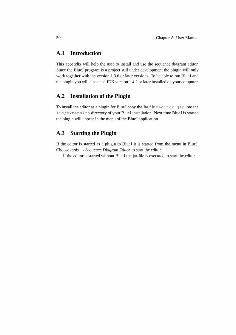
50 Chapter A. User Manual
A.1 Introduction
This appendix will help the user to install and use the sequence diagram editor.Since the BlueJ program is a project still under development the plugin will onlywork together with the version 1.3.0 or later versions. To be able to run BlueJ andthe plugin you will also need JDK version 1.4.2 or later installed on your computer.
A.2 Installation of the Plugin
To install the editor as a plugin for BlueJ copy the Jar fileMeditor.jar into thelib/extension directory of your BlueJ installation. Next time BlueJ is startedthe plugin will appear in the menu of the BlueJ application.
A.3 Starting the Plugin
If the editor is started as a plugin to BlueJ it is started from the menu in BlueJ.Choosetools→ Sequence Diagram Editorto start the editor.
If the editor is started without BlueJ the jar-file is executed to start the editor.

A.4. A Tutorial, Creation of a Sequence Diagram 51
A.4 A Tutorial, Creation of a Sequence Diagram
When the editor has been installed and started a sequence diagram can be created.This tutorial will illustrate when the editor is in BlueJ-mode using a project called“people2” which comes as an example with the BlueJ program. The scenario de-scribed in the sequence diagram will display a secretary registrating a new studentadding him or her to the database.
First an actor is added to the sequence diagram. This is done by clicking onthe icon for an actor, see figure A.1. The name of the actor is then changed to“Secretary” by double clicking on the actor or by choosing from the menu. Themenu of the actor is shown by clicking on the actor with the right mouse button.
Next step in the sequence diagram is the creation of a new student. The “Secre-tary” will create a new student to add to the database. This is done by first choosingto add a new message to the diagram, see A.1. Mark the start for the message onthe lifeline of the actor (“Secretary”). Then click with the right mouse button andthe editor will ask if“Do you want to create a new object with this message?”.Answering yes will create a new object. First choose which class the object shouldbe created from and then write the name of the object, see figure A.6. The sequencediagram will now look as in figure A.2.
Figure A.2. The actor and the new student have been added to the sequence diagram.

52 Chapter A. User Manual
Next step will be that the Secretary sets the address of the new student. This isdone by making a call to the method “setAddress” which the student has inheritedfrom its super class Person. The message call is made by first choosing to add anew message. First click on the lifeline of the actor, who will make the methodcall, then click on the lifeline of the student to which the call is made. Then choosewhich method to use in the drop down list and click “OK”. The diagram will nowlook as in figure A.3.
When a message is added to a sequence diagram the default in the editor is thatthe message gets a return message. If the type of the return value is known it willbe added to the return message. Return messages can be switched on and off in themenu underoption→ show return messages. This could be done any time duringthe development of the diagram.
If a message has been added to a sequence diagram and the position of it is notsatisfactory the message can be moved. This is done by selecting the message, byclicking on it, and then click on the handle1 of the message and hold the left mousebutton down and drag the message to the right position.
Figure A.3. The actor and the new student have been added to the sequence diagram. Theactor calls the method “setAddress” to let the student set its address.
1A little square that will appear when the message has been selected.

A.4. A Tutorial, Creation of a Sequence Diagram 53
When the method “setAddress” is called on the student it creates a new objectof the class Address and sets its own address. This has to be displayed in thesequence diagram by letting the student create a new object of the class Addressbefore returning the method call to setAddress, done by the actor. This is doneby choosing to add a new message. Mark the start point of the method call onthe lifeline of the student, since it is the student creating the new Address. Toclarify that the new Address is created before the method call to “setAddress”returns the start point of the message should be placed between the endpoint of the“setAddress”-message and the return message belonging to it. Then create a newobject from the class Address as described before. The look of the diagram willnow be as in figure A.4.
If a message, an actor, or an object has been added to the diagram but shouldbe deleted this is done by clicking on the component with the right mouse buttonand a menu will appear. Just choose “delete” from the menu and the componentwill be deleted from the sequence diagram.
Figure A.4. The student creates a new object of the class Address to be able to set its ownaddress.

54 Chapter A. User Manual
Next and last step in the sequence diagram will be the Secretary adding the newstudent to the database. First we have to add an object of the class Database to thesequence diagram. This is done by choosing to add a new object to the diagram byclicking on the icon for an object, see figure A.1. Then choose which class to createthe object from and write the name of the new object, see figure A.6. Now theSecretary adds the new student to the Database by calling the method “addPerson”in the database. To add this method call into the diagram first choose to add anew message, click on the lifeline of the actor and then click on the lifeline of thedatabase. Then choose which method in the list (“addPerson”) and click “OK”.The diagram will now look as in figure A.5.
Figure A.5. The finished sequence diagram.
Now the sequence diagram is complete and all objects and messages havebeen added. If the diagram has not been saved yet this is done by either press-ing Ctrl-S or choosingsave / save as from the file menu. The name ofthe sequence diagram is typed and then click “OK”, see figure A.9. The file of thediagram will be saved in the same directory as the project it belongs to, that is, thecurrently open project in BlueJ.

A.5. Adding Components to a Sequence Diagram 55
A.5 Adding Components to a Sequence Diagram
If the editor is started the user can choose to create a new sequence diagram oropen a saved one. To create a new sequence diagram the diagram is drawn in thedrawing area and later saved under the menufile → save as. Otherwise a savedsequence diagram is opened using the menufile→ open.
A.5.1 Adding an Actor
To add an actor to the sequence diagram just click on the icon for an actor, seefigure A.1, and an actor will be added to the drawing area.
A.5.2 Adding an Object
Figure A.6. If the editor is in BlueJ-mode the user first has to choose the class of the newobject (the window to the left) and then the name of the object (the window to the right).
To add an object to the sequence diagram click on the icon for an object, seefigure A.1. If the editor is in BlueJ-mode the class of the object first has to bechosen, see figure A.6. This is done by selecting one of the classes in the list andthen click on the “OK”-button. After this the user has to fill in the name of thenew object. If a new name is not given the object will be given a default name like“object1”.
A.5.3 Adding a Message
To add a message to the sequence diagram click on the icon for a message, seefigure A.1. To select the start object of the message, meaning the object makingthe method callto the end object, click on the lifeline on this object (or actor).To select the end object of the message click on the lifeline of this object. If theeditor is in BlueJ-mode the user has to choose a method. This is done by selectingone method in the list and click on the “OK”-button, see figure A.7. If the option“Show return messages” is selected in the menu underoptioneach added message

56 Chapter A. User Manual
Figure A.7. If the editor is in BlueJ-mode and a message is added the user has to choosewhich method to add by selecting one from the list.
will get a return message belonging to it. If the return message has a type this willbe added as a label to the return message.
A.5.4 Adding a Destroy Symbol
A destroy symbol can be added to an object or to an actor. This is done by clickingon the object or actor with the right mouse button and a popup menu will appear.The destroy symbol is added by selectingcreate destroysymbolin the menu andthen click on the lifeline of the object or actor where the destroy symbol should beplaced.
A.5.5 Notes about the Sequence Diagram
Figure A.8. The window where the user can write notes belonging to a sequence diagram.
Each sequence diagram has a note (a text field) belonging to it. The note cancontain information about the diagram for example if the user wants to point outsomething special about the diagram, a general description of the scenario etc, heor she can write it here. To write notes for a sequence diagram just click on the

A.6. Save and Open a Sequence Diagram 57
icon for notes, see figure A.1. Then a window will appear, see figure A.8, wherethe notes can be written. Before closing the window click on thesavebutton andthe notes will be saved together with the sequence diagram.
A.5.6 Return Messages
Every message that is added to a sequence diagram will automatically get a returnmessage. If the editor is in BlueJ-mode the type of the return message will beadded as the label of the return message. The user can choose whether to displaythe return messages or not. This is done underoption→ Show return messages.Return messages can be switched on and off during the development of a sequencediagram.
A message having the same object as its start and end object will not get areturn message.
A.5.7 Creation of a sequence
Messages added to a sequence diagram can be arranged in a sequence. All mes-sages, including return messages, in a sequence will automatically be arrangedwith the same distance between them. If a message in a sequence is removed themessages after the removed message will be removed from the sequence.
To add message-M2 to a sequence after message-M1 message-M2’s start pointhas to be placed between message-M1’s endpoint and its return message. If thisis done message-M2 will be added to the sequence and all messages and returnmessages in the sequence will automatically be arranged.
A.6 Save and Open a Sequence Diagram
Figure A.9. If the editor is in BlueJ-mode and the sequence diagram should be saved theuser just has to fill in the name of the file
To save a sequence diagram chosefile → save as / save. If the editor is inBlueJ-mode only the filename has to be filled in, see figure A.9. The file of thesequence diagram will be saved in the same directory as the project it belongs to.

58 Chapter A. User Manual
If the editor is not in BlueJ-mode the user chooses the name of the file and thedirectory where the file should be saved. To save a sequence diagram the user canalso pressCtrl-S .
To open a saved sequence diagram choosefile → open. Then choose whichfile to open and click OK. If the editor is in BlueJ-mode only the files belongingto the currently open project are shown. To open a sequence diagram the keyboardcan be used by pressingCtrl-O .
A.7 Moving, Deleting and Editing
A.7.1 Objects
Delete To delete an object click on the object with the right mouse button andchoosedeletefrom the popup menu. When deleting an object all attributesbelonging to it will also be deleted, such as messages, destroy symbol, life-line etc.
Rename An object can be renamed in two different ways. The name can bechanged via the menu that appears when the object is clicked on with theright mouse button. The name can also be changed by double clicking onthe object.
Move To move an object first select the object by clicking on it. The object willthen be drawn in red and a handle (a small square) will appear. To move theobject click on the handle and “drag” the object (with the left mouse buttonpressed down) to the new position. When the mouse is released all objectsand actors in the sequence diagram will be rearranged automatically and thedistance between them will be the same.
A.7.2 Actors
Delete To delete an actor click on the actor with the right mouse button and choosedeletefrom the popup menu. If an actor is deleted, all attributes belongingto it, like messages, destroy symbol, lifeline etc. will also be deleted.
Rename An actor can be renamed in two different ways. The name can be changedvia the menu that appears when the actor is clicked on with the right mousebutton. The name can also be changed by double clicking on the actor.
Move To move an actor, first mark it by clicking on the actor. The actor will thenbe drawn in red and a handle (a small square) will appear. To move the actor

A.7. Moving, Deleting and Editing 59
click on the handle and “drag” the actor (with the left mouse button presseddown) to the new position.
A.7.3 Messages
Delete To delete a message click on the message with the right mouse button andchoosedeletefrom the popup menu. The message will then be deleted. Ifthe message has a return message this return message will also be deleted.
Rename There are two ways to rename a message. The message can be renamedby clicking on the message with the right mouse button and choosechangemessagefrom the popup menu. The message can also be changed by doubleclicking on it. Return messages can also be renamed in the same way.
Move If a message is selected by clicking on it a handle appears. By clicking onthis handle and dragging it, the message (or return message) can be movedvertically.
Creation messageIf a message is to create a new object this is done by first se-lecting the start object for the message, the object that is going to create thenew object. Then click with the right mouse button and the editor will let theuser choose which new object to create. The new object will then be addedto the sequence diagram.
A.7.4 Destroy Symbol
Delete To delete a destroy symbol click on it with the right mouse button andchoosedeletefrom the popup menu.
Move To move a destroy symbol select it by clicking on it. The destroy symbolwill then be drawn in red and a handle will appear in the middle. To movethe destroy symbol click on the handle and “drag” the destroy symbol (withthe left mouse button down) to the new position. The destroy symbol canonly be moved up or down along the lifeline it belongs to.
A.7.5 Lifeline
The length of a lifeline can be changed. To change the lifeline first mark it byclicking on it. The lifeline will then be drawn in red and a handle will appear atthe end of the lifeline. To change the length of the lifeline click on the handle and“drag” the handle to the new position for the end of the lifeline. The handle canonly be moved vertical along the lifeline.

60 Chapter A. User Manual
A.8 Known Bugs
There are a number of known bugs in the editor and surely a number of unknowntoo. Since the program still needs some adjustments and more functionality thereare some features left to implement. One of the biggest bug is that the program isnot all “waterproofed”, it is not that hard to have it crash. If the editor is correctlyused it works OK, but if the user starts to “test” the program there will probablyhappen strange things.
The known bugs in the editor are:
SequencesIf a sequence contains two messages which are messages back to thesame object in a row this will cause problems. New messages can only beadded at the end of the sequence and not in the middle of an already existingsequence.
Consistency checkWhen a sequence diagram is opened it is checked against aBlueJ project. But only classes are checked and not methods.
Moving components Sometimes when different objects or actors are rearrangedin the drawing area all attributes belonging to them do not get the correctnew position.
Creation messagesA creation message can not be in a sequence of messages.
Return messagesWhen a regular message is added to the sequence diagram itgets a return message placed in the right positon. But later on the user canmove this return message to any position without any controll from the edi-tor.
Inheritance If a classA inherits from classB, all classB’s public methods are alsoshown for classA. But if classB inherits from classC, classC’s public meth-ods should be shown for classA which is not the case. The inheritance is justshown in one step in the editor.
Related Documents