QEX – January/February 2015 31 Reprinted With Permission © ARRL Sivan Toledo, 4X6IZ School of Computer Science, Tel-Aviv University, Tel-Aviv 69978, Israel: [email protected] A Selective Robust Weak- Signal UHF Front End The author presents a 431 to 435 MHz external front end for a USRP N200 Ettus Research transceiver. 1 Notes appear on page 36. Quite a few modern wideband receivers do not have a selective front-end that can receive weak signals while rejecting strong out-of-band signals. This article explains the issues involved in the design of external front ends for such receivers and describes a concrete front-end unit and its performance. The unit we describe was designed for a Universal Software Radio Peripheral (USRP) N200 radio with a WBX RF daughter card and for 431 to 435 MHz signals, but the design can be easily adapted to other bands and radios. The WBX is a direct-conversion IQ transceiver that feeds the IQ analog-to- digital (ADC) and digital-to-analog (DAC) converters on the USRP motherboard. The ADCs and DACs are controlled by a field programmable gate array (FPGA) that performs some digital signal processing (up/down sampling and the required anti- aliasing filtering) and sends/receives samples from a computer. Demodulation and other processing tasks are typically done by the computer. Figure 1 shows a simplified block diagram of the receive chain of the WBX, which covers 50 to 2200 MHz. The receiver response is essentially flat across this frequency range; any signal in this range that is present at the antenna connector of the WBX reaches the mixer. In theory, the mixer translates signals near the frequency of the local oscillator (LO) to frequencies near DC, which the post-mixer anti-aliasing filters pass to the ADCs. Signals far away from the LO are translated to high frequencies that the anti-aliasing filters block. But in practice, strong out-of-band signals generate intermodulation products in the mixer or in the amplifiers that precede it. Some of these spurious signals are often within the passband of the anti-aliasing filters, so they generate interference at the ADC, possibly even causing saturation. This implies that the WBX and similar radios require a selective external front end if they are used to receive weak signals in the presence of strong signals. 1 In many areas, simply connecting the radio to an external antenna guarantees reception of strong signals (cellular base stations, broadcast radio and television, and so on). A selective front-end can also help the WBX cope with out-of-band signals whose frequency is close enough to that of signals of interest to pass the analog post-mixer anti-aliasing filter (say 15 MHz away). Such signals can saturate in the ADCs even if they are not strong enough to cause intermodulation. A saturated ADC produces no useful data. AGC action can reduce the gain of the WBX to prevent saturation, but this gain reduction also reduces the dynamic range available for weak signals of interest (effectively, the ADC represents them using fewer bits per sample). QX1501-Toledo01 Local Oscillator MGA62563 MGA82563 –1.5 dB to –33 dB –3 dB ADA4937 20 MHz Mixer ADL5387 50 MHz ADC Anti-aliasing Filter Anti-aliasing Filter Figure 1 — A highly simplified block diagram of the receive chain of the Ettus WBX RF daughter board (and the ADC, which completes the analog chain and is part of the USRP motherboard). The diagram omits the antenna selection and transmit/receive switches. The signal chain that follows the mixer is complex (separate I and Q channels). The MGA82563 and the mixer are protected from high input power, but this is not shown on the published schematics of the WBX; see text for details.

Welcome message from author
This document is posted to help you gain knowledge. Please leave a comment to let me know what you think about it! Share it to your friends and learn new things together.
Transcript

QEX – January/February 2015 31 Reprinted With Permission © ARRL
Sivan Toledo, 4X6IZ
School of Computer Science, Tel-Aviv University, Tel-Aviv 69978, Israel: [email protected]
A Selective Robust Weak-Signal UHF Front End
The author presents a 431 to 435 MHz external front end for a USRP N200 Ettus Research transceiver.
1Notes appear on page 36.
Quite a few modern wideband receivers do not have a selective front-end that can receive weak signals while rejecting strong out-of-band signals. This article explains the issues involved in the design of external front ends for such receivers and describes a concrete front-end unit and its performance. The unit we describe was designed for a Universal Software Radio Peripheral (USRP) N200 radio with a WBX RF daughter card and for 431 to 435 MHz signals, but the design can be easily adapted to other bands and radios.
The WBX is a direct-conversion IQ transceiver that feeds the IQ analog-to-digital (ADC) and digital-to-analog (DAC) converters on the USRP motherboard. The ADCs and DACs are controlled by a field programmable gate array (FPGA) that performs some digital signal processing (up/down sampling and the required anti-aliasing filtering) and sends/receives samples from a computer. Demodulation and other
processing tasks are typically done by the computer.
Figure 1 shows a simplified block diagram of the receive chain of the WBX, which covers 50 to 2200 MHz. The receiver response is essentially flat across this frequency range; any signal in this range that is present at the antenna connector of the WBX reaches the mixer. In theory, the mixer translates signals near the frequency of the local oscillator (LO) to frequencies near DC, which the post-mixer anti-aliasing filters pass to the ADCs. Signals far away from the LO are translated to high frequencies that the anti-aliasing filters block. But in practice, strong out-of-band signals generate intermodulation products in the mixer or in the amplifiers that precede it. Some of these spurious signals are often within the passband of the anti-aliasing filters, so they generate interference at the ADC, possibly even causing saturation. This implies that the WBX and similar radios require a selective
external front end if they are used to receive weak signals in the presence of strong signals.1 In many areas, simply connecting the radio to an external antenna guarantees reception of strong signals (cellular base stations, broadcast radio and television, and so on).
A selective front-end can also help the WBX cope with out-of-band signals whose frequency is close enough to that of signals of interest to pass the analog post-mixer anti-aliasing filter (say 15 MHz away). Such signals can saturate in the ADCs even if they are not strong enough to cause intermodulation. A saturated ADC produces no useful data. AGC action can reduce the gain of the WBX to prevent saturation, but this gain reduction also reduces the dynamic range available for weak signals of interest (effectively, the ADC represents them using fewer bits per sample).
QX1501-Toledo01Local
Oscillator
MGA62563 MGA82563
–1.5 dB to–33 dB
–3 dB
ADA493720 MHz
MixerADL5387 50 MHz ADC
Anti-aliasingFilter
Anti-aliasingFilter
Figure 1 — A highly simplified block diagram of the receive chain of the Ettus WBX RF daughter board (and the ADC, which completes the analog chain and is part of the USRP motherboard). The diagram omits the antenna selection and transmit/receive switches. The signal chain that follows the mixer is complex (separate I and Q channels). The MGA82563 and the mixer are protected from high input power, but this is
not shown on the published schematics of the WBX; see text for details.
32 QEX January/February 2015 Reprinted With Permission © ARRL
Selectivity is not the only property that a weak-signal front end for the WBX should have. The WBX has a lot of gain and a fairly good noise figure (5 dB), but for signals near or below the thermal noise floor, more gain and a lower noise figure are helpful. This brings us to the second requirement for our front-end unit: low-noise amplification. As in any front end design, the low-noise amplifier (LNA) can also eliminate the noise-figure degradation that might be caused by the antenna-to-receiver cable and by selective filters.
The requirements so far, selectivity and low-noise amplification, are not new and many existing front-end designs satisfy them to some extent. Currently available and well-documented examples include Sam Jewell’s VLNA series, which offers low noise, high gain, but little filtering , LNAs from Down East Microwave (single stage with less gain than the VLNA but somewhat more filtering), the EXTRA series by Gyula Nagy (single stage with a output helical filter, providing more selectivity than the previous two).2. 3. 4 All of these LNAs have a noise figure of less than 1 dB.
Unfortunately, none of the available units offers narrow filering. I tried to use a chain
of two Down East Microwave LNAs with a connctorized ready-made bandpass filter from Cross Country Wireless between them, but the radio still suffered from periods of strong out-of-band interference.5 Increasing the attenuation in the variable attentuator between the MGA62563 and the MGA82563 using an AGC algorithm prevented saturation, but it also resulted in loss of weak-signal reception. This filter is fairly expensive (over $90) and I was not able to find alternative connectorized filters with more selectivity at a similar or lower cost.
All the available LNAs that I could find had another problem: they can usually destroy the WBX and similar radios if a strong signal is present at their input. Some similar radios are prone to self-destruction even without an LNA (the WBX is apparently not prone to such self destruction; see below). The next section analyzes this issue.
Safe Power Limits in Receive Chains
Receiver front-ends are optimized for weak signals coming from the antenna, but in certain situations they can be subject to relatively powerful signals. Strong signals
can appear at the front-end, either due to a powerful nearby transmitter (including out-of-band broadcast transmitters) or due to leakage from our own transmitter. High-enough power will destroy the front-end of any receiver, but some receivers can withstand more input power than others, making them more robust. For example, the Icom IC-R9500 receiver is specified to withstand 5 W of RF input, which is very robust, whereas the Agilent N9000A spectrum analyzer can only withstand –10 dBm in some configurations when the preamplifier is on, and with no input attenuation.6 Unfortunately, the safe input level of most receivers, including the WBX, is not specified by the manufacturers.
To understand the potential for physical damage by strong signals, let us consider the first few stages of the signal chain of the WBX, including an external LNA mounted near the antenna, such as the DEM 432LNA. Table 1 shows the maximum input power each stage is rated for, the output power at 1 dB compression, which is a lower bound on the maximum power the stage can generate, and the gain for each of the four stages. A device specified with a P1 dB output (output
Table 1Safe Input Levels
DEM 432LNA MGA62563 MGA82563 ADL5387Pin maximum 22.4 dBm 21 dBm 13 dBm 15 dBmPout at 1dB compression 19 dBm 18 dBm 17.4 dBm 12.7 dBmGain 17 dB 22 dB 14.7 dB 4.4 dBm
Note: Possible high output levels (P1 dB), and gain of an external LNA and the first three active stages in the WBX. The data for the MGA62563, MGA82563, and the ADL5387 are from the manufacturers’ data sheets.
QX1501-Toledo02
AmplifierAttenuatorJ1
C11 nF
BPF1 C21 nF
C31 nF
Limiter C41 nF
BPF2 C51 nF J2
RFC220 nH
D1C6
100 μFC7
0.1 μFRegulator
C80.1 μF
C91 nF
C101 μF D2
R1
Vin
5 V
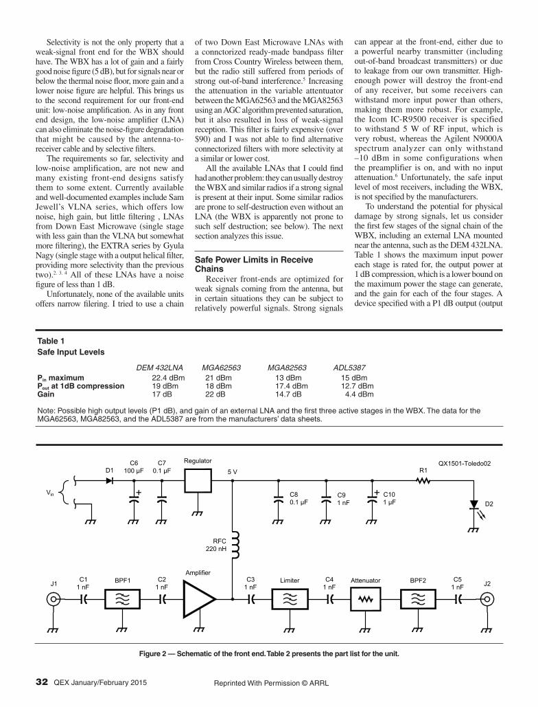
Figure 2 — Schematic of the front end. Table 2 presents the part list for the unit.
QEX – January/February 2015 33 Reprinted With Permission © ARRL
power at 1 dB compression) of 18 dBm, for example, can certainly generate 18 dBm of RF power at its output. At this output level the device is already somewhat non-linear, but it is usually not yet saturated. The non-linearity increases at higher power, so typical devices can generate a bit more power than their P1 dB specification, but not much more; 2 to 3 dB is a reasonable estimate. The receive chain also contains switches (omitted from Figure 1), attenuators, and other passive components, but these can tolerate higher power levels than active components so we ignore them here (they do need to be included in a formal anlysis).
The data for the DEM 432LNA are from the DEM data sheet for the LNA, except for the maximum input power, which is taken from the data sheet of the active device in the amplifier, the FPD750SOT89.The data in the table shows that each one of these stages is probably capable of destroying the next. For example, if the MGA62563 is presented with –3 dBm at its input, it will amplify it by 21 dB to 18 dBm (22 minus the 1 dB compression). If the variable attenuator is set to –1.5 dB, the MGA82563 sees 16.5 dBm at its input, which exceeds its limit by 3.5 dB.
A somewhat optimistic estimate of the maximum safe input power level of the WBX (for the components up to the mixer) is 15 dBm + 3 – 14.7 + 1.5 – 22 = –17.2 dBm. If we include a 19 dB LNA, the safe input level drops to around –36.2 dBm. The estimate is optimistic in the sense that we assume that amplifiers do not generate more power than their P1 dB specification, so a conservative estimate might be 3 dB or so lower, to cover the possibility that the last amplifier in the chain is saturated. The safe power level varies with frequency, because of filtering (here only in the external LNA if one is used) and because the gain of the amplifiers varies a bit with frequency (the gains cited above for 432 MHz or so).
If we can ensure that there are no signals stronger than about –40 dBm at the input of the external LNA, we are all set; we won’t destroy the LNA or the WBX. But if we want to ensure that the receiver won’t be damaged by higher power levels, we need to improve the design of the front end.
There are two complementary ways to make the front-end more robust. One is to add limiters that limit the power at certain points in the receive chain, and the other is to add filters. A limiter is an RF circuit that behaves like a very mild attenuator at low power levels but reflects most of the input power back at high power levels (the device becomes an RF short when input power is high), thereby protecting sensitive devices that follow it in the receive chain. Limiters are typically implemented using PIN diodes
and they usually limit at 0 to 14 dBm output or so.7
Matt Ettus of Ettus Research told me that the WBX includes protection for the MGA82563 and the mixer, so we only need to ensure that we do not destroy the MGA62563.8
Filters help protect receivers by preventing strong out-of-band signals from reaching the receiver, potentially damaging it. When used in front of a limiter, as in the design described here, they reduce the likelihood that a strong out-of-band signal will trigger any limiting action that would distort weak in-band signals.
DesignFigure 2 shows the schematic of the
UHF front-end that I designed to improve
the performance of the WBX. The front end is intended to follow a mast-top DEM 432LNA, but it can also be fed directly from the antenna. The signal chain starts with a helical filter, followed by an internally matched PGA-103+ amplifier with a gain of about 22 dB, a noise figure of about 0.5 dB, and P1 dB of about 21.5 dB (all specified at 400 MHz). The amplifier is followed by an RLM-33+ limiter, which limits power at about 12 dBm (at 400 to 500 MHz; it can output slightly more power at higher frequencies; its input 1 dB compression point is 5 dBm), a 3 dB attenuator, and a SAW filter. All the components are internally matched to 50 W.
The limiter-attenuator combination ensures that the 10 dBm input-power limit of the SAW filter is never exceeded. A 5 dB attenuator would provide wider margins and
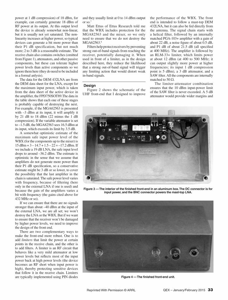
Figure 3 — The interior of the finished front-end in an aluminum box. The DC connector is for input power, and the BNC connector powers the mast-top LNA.
Figure 4 — The finished front-end unit.
34 QEX January/February 2015 Reprinted With Permission © ARRL
is probably preferable. The insertion loss of the SAW filter is about 2 dB, so the WBX should see no more than 7 dBm at its input, which is safe. The limiter itself is rated at 33 dBm (2 W), which is more than the PGA-103+ can generate, so it cannot be destroyed in this circuit either. The PGA-103+ can withstand a 21 dBm input, and because the insertion loss of the helical filter is 3 dB, the overall front-end unit can tolerate up to 24 dBm at its input (The helical filter can withstand a 1 W input, so it does not limit the safe input level). This implies that it can be used safely when connected to a mast-top 432LNA, which is unlikely to produce more than 24 dBm. The run of coax between the mast-top LNA and the front-end unit provides an additional margin of protection.
The SAW filter is very sharp and provides excellent selectivity. The helical filter does not provide much additional selectivity, but as explained above, it reduces the likelihood that out-of-band signals will trigger limiting action that distorts in-band signals. I included the helical filter in the design for another reason. I was worried that the narrow SAW filter will have wide variations in group delay (the time a signal is delayed in the filter) within its passband. This is harmless for narrow-band applications, but troublesome in applications that need to accurately estimate the arrival time of signals. The inclusion of the helical filter, whose group delay is much flatter, allows the unit to achieve reasonable selectivity even if the SAW filter is not used. As you will see in the measurements section below, within the center of the passband of the SAW filter its group delay is fairly constant, so this turned out not to be an important issue. On the other
hand, the helical filter is the most expensive component in the front-end unit, so dropping it from the design is not unreasonable. Of the other components, the most expensive are the limiter and the SMA connectors.
T h e p ow e r s u p p l y s e c t i o n i s straightforward. It can use either a standard linear regulator (78M05, the one that is also used in the 432LNA), or a low-dropout (LDO) replacement, TL720M05. The LDO requires a higher-value output capacitor for stability, but otherwise the two regulators are similar, except that the LDO can function down to 5.5 V, whereas the 78M05 requires a 7.5 V input.
The PGA-103+ is rated from 50 to 4000 MHz (with somewhat degraded performance at the high end) and the limiter is rated for 30 to 3000 MHz, so the unit can be easily adapted to other bands. Helical filters with the same circuit board layout are available for other bands (center frequencies of 146 MHz and 1270 MHz); finding a suitable SAW filter for other bands may be more of a challenge. The values of blocking capacitors and of the choke may need to be adapted to other bands.
ConstructionI built the first unit on a piece of double-
sided copper-clad board in which I cut out some of the copper by hand, in order to quickly test the design. For the next version I designed a circuit board and had a few made by a low-cost US-based manufacturer (OSH Park, which charged about $20 for 3 identical boards). The schematic and circuit board design files are available for download from the ARRL QEX files website.9
Making the first board by hand was not trivial, so in hindsight, I should have started off with a manufactured circuit board. Readers interested in the hand-made technique, which does produce good UHF circuits even with tiny components (the SAW filter is 3 mm × 3 mm with 0.38 mm separation between pads), can read about it in my blog.10
The circuit board uses mostly surface-mount devices. Capacitors and the choke are in 0603 packages. There’s generous space around components, making the board easy to assemble. I probably could have shrunk the layout quite a bit without hurting ease-of-assembly much.
PerformanceI measured the performance of the front-
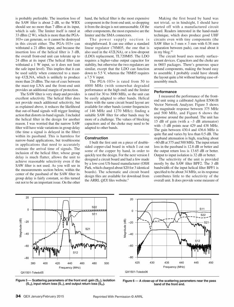
end unit using a calibrated Agilent E5061B Vector Network Analyzer. Figure 5 shows the magnitude response between 375 MHz and 500 MHz, and Figure 6 shows the response around the passband. The unit has 15 dB of gain (with a –3 dB attenuator) with –3 dB points near 429 and 438 MHz. The gain between 430.4 and 436.6 MHz is quite flat and varies by less than 0.5 dB. The stopband attenuation is high, reaching about –60 dB at 375 and 500 MHz. The input return loss in the passband is 12.8 dB or better and the output return loss is 13.65 dB or better. Output to input isolation is 32 dB or better.
The selectivity of the unit is provided mostly by the SAW filter BPF2. The 3 dB bandwidth of the input helical filter BPF1 is specified to be about 34 MHz, so its response contributes little to the selectivity of the overall unit. It does provide some measure of
QX1501-Toledo05
Mag
nitu
de (d
B)
Frequency (MHz)380
‒80
500
20
S21
S12
S22
S11
400 420 440 460 480
‒60
‒40
‒20
0
QX1501-Toledo06
Mag
nitu
de (d
B)
Frequency (MHz)425
‒80
450
20
430 435 440 445
‒60
‒40
‒20
0
S21
S12
S22
S11
Figure 5 — Scattering parameters of the front end: gain (S21), isolation (S12), input return loss (S11), and output return loss (S22).
Figure 6 — A close-up of the scattering parameters near the pass band of the front end.

QEX – January/February 2015 35 Reprinted With Permission © ARRL
Figure 9 — Gain measurements used for estimating intercept and compression
points.
Table 2 Parts List for the Front-End Unit
Designator Manufacturer Part Number PriceBPF1 Temwell TT67295B-435M $18BPF2 RF Monolithics SF2136E $0.75Amplifier Mini-Circuits PGA-103+ $2Limiter Mini-Circuits RLM-33+ $10Attenuator Mini-Circuits LAT-5+ or LAT-3+ $2Regulator Texas Instruments TL720M05 or 78M05 $1.23RFC — 220 nH 0606 TE Connectivity 9-1624112-0 $0.47C1, 2, 3, 4, 5, 9 Kemet or others 1 nF 0603 $0.02C7, 8 Kemet or others 0.1 mF 0603 $0.02C6 Panasonic or others 100 mF 35 V electrolytic $0.78C10 Nichicon or others 1 mF 10 V for 78M05 or 47 mF 10 V for TL720M05 tantalum $1D1 Diodes Inc or others Schottky 40 V 1 A $0.45D2 Kingbright or others 3 mm green LED $0.13R1 Any 180 W 0805 or adjust for LED $0.02J1, 2 Molex or others SMA card-edge jack with nut $6.70
Prices are approximate and reflect the pricing for the small quantities required for one unit. Temwell and Mini-Circuits have minimum-order requirements; all the other parts are available from Digi-Key and other distributors in small quantities.
QX1501-Toledo08
S21
Gro
up D
elay
(ns)
Frequency (MHz)
0
440
300
425 430 435
100
200
Figure 7 — The magnitude response of the SAW filter, taken from the manufacturer’s
data sheet dated 2/10/2011.
Figure 8 — Input-to-output delay in the front end.
QX1501-Toledo07
dB
MHz
–80
0
430410390 450 470 490
433.
92–60
–40
–20
Magnitude response (S21)of the SF2136E SAW filter
QX1501-Toledo09
Out
put P
ower
(dB
m)
Input Power (dBm)–40
–120
10
40
–30 –20 –10 0
–80
–40
0Fundamental
3rd Order Products
protection to the amplifier from strong way-out-of-band signals.
Figure 7 shows the magnitude response of the SAW filter alone. We can see that it is the main determinant of the response of the entire unit. The two responses are similar not only in terms of the bandwidth, but also in terms of details like the smooth rolloff toward lower frequencies and the two “shoulders” in the rolloff toward higher frequencies.
Figure 8 shows the group delay of the unit. The input-to-output delay in the front end is high, up to 283 ns (at 437.7 MHz). Within the center of the passband, between 431 and 435 MHz, the delay is smaller, around 150 ns. The VNA output indicates that the group delay is noisy (variation of about 50 ns between 431 and 435 MHz), but at least some of this is probably due to noise in the measurement of the phase response of the unit and in the numerical
differentiation that computes the delay from phase measurements. The high delay is a result of the relatively narrow and sharp filter, so it is not unexpected.
I also measured the 1 dB compression point and the 3rd order intercept point of the unit. The measurements were done using an Agilent N9010A signal analyzer (used as a spectrum analyzer), an Agilent N5171B signal generator, and a Mini-Circuits ZFSC-2-4-S+ splitter-combiner. For two-tone measurements, the second signal generator consisted of a VWNA 3E network analyzer used as a signal generator together with a DEM 432MHz LNA. The results of the measurements (shown in Figure 9) show that the gain of the unit under test was 14.6 dB, that the input-referenced 1 dB compression point is –11 dBm (output referenced 2.6 dBm), and that the output-referenced 3rd order intercept point is 19.25 dBm
(input referenced 4.66 dBm). The intercept and compression points of the units are determined primarily by the limiter, not by the PGA-103+ amplifier. The PGA-103+ output 1 dB compression point is 21.5 dB, whereas the limiter input 1 dB compression point is much lower, at 5 dBm.
ConclusionsHighly-integrated receivers and
transceivers with wide frequency coverage are available for VHF, UHF and above. They are available in a wide range of prices and performance levels, ranging from sub-$20 USB-dongle receivers to transceivers costing hundreds or thousands of dollars (obviously at much higher levels of performance).11
In spite of the high level of integration, most of these receivers and transceivers lack a high-performance front-end. Designing a

36 QEX January/February 2015 Reprinted With Permission © ARRL
low-noise amplifier is not hard (especially given the availability of low-cost, low-noise internally-matched integrated amplifiers). Ready-made filters are somewhat harder to find, because they are frequency and bandwidth specific, but for some frequency-bandwidth combinations, commercially-available SAW filters can give excellent results at low cost. Ensuring that the external front-end does not damage the receiver is more challenging, however, and this topic has not received much attention. Hopefully this article will result in safer high-performance front ends.
It is also worth noting that the unit is designed for weak signals and that it does not cope well with strong in-band signals, especially when it is coupled with a mast-mounted LNA. Strong in-band signals amplified by the amplifier or amplifiers that precede the limiter and the receiver can cause severe intermodulation. Far out-of-band signals are less of an issue because they are attenuated by the two filters in this unit (and by band-pass filters in the mast-mounted LNA).
The research reported in this article was supported by the Minerva Center for Movement Ecology. Sivan Toledo, 4X6IZ, is Professor of Computer Science at Tel-Aviv University. He holds BS and MS degrees from Tel-Aviv University and a PHD from the Massachusetts Institute of Technology, where he was also Visiting Associate Professor in 2007 – 2009. He was first licensed in 1982.
Notes1The vendor of the USRP and WBX, Ettus
Research, also produces similar RF daugh-ter boards for higher frequencies (SBX and CBX). More generally, many modern receiv-ers and transceivers with a similarly-wide frequency coverage usually have little or no front-end selectivity because of the difficulty of producing tunable band-pass filters.
2Sam Jewell, “VLNA: A Very Low Noise (Pre)-Amplifier for the UHF 70 cm to 9 cm Bands,” Version E1, 2013. PDF documentation at http://www.g4ddk.com/.
3A variety of low noise amplifiers, including the one used in this design, are avail-able from Down East Microwave; www.downeastmicrowave.com/PDF/l-lna.PDF.
4More information about the Extra series of preamplifiers by Gyula Nagy, HA8ET, is
available on his website: www.ha8et.hu/.5For more information about the Cross
Country Wireless band-pass filters, go to: www.crosscountrywireless.net/filter.htm.
6It would be much better if the manufacturers would do the testing to determine the maxi-mum safe input level than to have users discover that level accidentally.
7For a technical background on PIN-diode limiters, see Skyworks Application Note “PIN Limiter Diodes in Receiver Protectors,” at: www.skyworksinc.com/uploads/documents/200480C.pdf, 2004. Originally published as “PIN-LImiter Diodes Effectively Protect Receivers,” EDN, Dec 17, 2004, pp 50 – 64.
8The limiter is not shown in the schematics of the WBX; In personal correspondence with Mat Ettus, the designer of the WBX, he told me that it is there.
9The schematic and circuit board design files for this project are available for download from the ARRL QEX files website. Go to www.arrl.org/qexfiles and look for the file 1x15_Toledo.zip.
10Read the author’s technical Blog at: http://sivantoledotech.wordpress.com/.
11Current examples include USRP receivers and transceivers from Ettus Research start-ing at $775, BladeRF from Nuand starting at $420, the FUNcube-dongle receivers at about $200, and sub-$20 DVB-T dongles that can be used as general-purpose sam-pling receivers.
Related Documents