Journal of VLSI Signal Processing 23, 93–107 (1999) c 1999 Kluwer Academic Publishers. Manufactured in The Netherlands. A Scalable Architecture for MPEG-4 Wavelet Quantization BART VANHOOF, MERCEDES PE ´ ON, GAUTHIER LAFRUIT, JAN BORMANS, LODE NACHTERGAELE AND IVO BOLSENS IMEC, Kapeldreef, 75, B-3001 Heverlee, Belgium Abstract. Wavelet-based image compression has been adopted in MPEG-4 for visual texture coding. All wavelet quantization schemes in MPEG-4—Single Quantization (SQ), Multiple Quantization (MQ) and Bi-level Quantization—use Embedded Zero Tree (EZT) coding followed by an adaptive arithmetic coder for the compression and quantization of a wavelet image. This paper presents the OZONE chip, a dedicated hardware coprocessor for EZT and arithmetic coding. Realized in a 0.5 μm CMOS technology and operating at 32 MHz, the EZT coder is capable of processing up to 25.6 Mega pixel-bitplanes per second. This is equivalent to the lossless compression of 31.6 8-bit grayscale CIF images (352 × 288) per second. The adaptive arithmetic coder processes up to 10 Mbit per second. The combination of the performance of the EZT coder and the arithmetic coder allows the OZONE to perform visual-lossless compression of more than 30 CIF images per second. Due to its novel and scalable architecture, parallel operation of multiple OZONEs is supported. The OZONE functionality is demonstrated on a PC-based compression system. 1. Introduction MPEG-4 [1] aims at providing a solution that scales the communication of multimedia content over hetero- geneous access networks and decoding facilities. The ultimate goal is to reach a “create once, decode every- where” situation. The key capability that is missing for achieving this goal in current visual coding systems is compression for scalable image quality and image size. When rendering a 3D scene, objects that are near to the horizon only need very coarse textures of perhaps just a few pixels. As objects become closer to the posi- tion of the viewer, more detailed textures are required to obtain natural looking scenes. Current 3D applications use de-facto 3D graphics API’s such as OpenGL and Direct3D. Hereby the uncompressed textures are read into memory first. Only then, downsampling and filter- ing generate the required successive lower resolution versions. This technique works well in a PC environ- ment where applications are mostly distributed on CD- ROM. However, the data volumes typically found on CD-ROM are way too large for streaming 3D content over the Internet. Hence, compression of the 3D scenes and associated textures is required. This is the purpose of MPEG-4 wavelet based visual texture coding. During wavelet transformation, the input image is decomposed by successive 2D filtering and subsam- pling into an Average Image and Detail Images, as shown in Fig. 1. When separable filters are used, the 2D filtering is performed by a horizontal and a verti- cal 1D convolution. The wavelet transformation is re- cursively executed on the lowpass filtered image from each level. Due to its recursive nature, the wavelet transform provides automatically a set of scaled im- ages: each lowpass filtered image can be considered as a scaled version of the original image. Typically the last Average image (i.e. A3 in Fig. 1) and the Detail Images are compressed separately. The Average Image is losslessly compressed using a lossless JPEG based compression technique. The Detail Images are com- pressed using a zero-tree based compression approach. The Single Quantization (SQ) uses a single-pass ap- proximation scheme. The Multiple Quantization (MQ) uses a multi-pass approximation scheme. The Bi-level Quantization (BQ) is a refinement of the MQ scheme, where successive approximation values are halved. A typical MPEG-4 wavelet compression chain is shown in Fig. 2. Minimal power dissipation and high throughput are crucial for both the mobile and the high-end application

Welcome message from author
This document is posted to help you gain knowledge. Please leave a comment to let me know what you think about it! Share it to your friends and learn new things together.
Transcript
Journal of VLSI Signal Processing 23, 93–107 (1999)c© 1999 Kluwer Academic Publishers. Manufactured in The Netherlands.
A Scalable Architecture for MPEG-4 Wavelet Quantization
BART VANHOOF, MERCEDES PEON, GAUTHIER LAFRUIT, JAN BORMANS,LODE NACHTERGAELE AND IVO BOLSENSIMEC, Kapeldreef, 75, B-3001 Heverlee, Belgium
Abstract. Wavelet-based image compression has been adopted in MPEG-4 for visual texture coding. Allwavelet quantization schemes in MPEG-4—Single Quantization (SQ), Multiple Quantization (MQ) and Bi-levelQuantization—use Embedded Zero Tree (EZT) coding followed by an adaptive arithmetic coder for the compressionand quantization of a wavelet image. This paper presents the OZONE chip, a dedicated hardware coprocessor forEZT and arithmetic coding. Realized in a 0.5µm CMOS technology and operating at 32 MHz, the EZT coder iscapable of processing up to 25.6 Mega pixel-bitplanes per second. This is equivalent to the lossless compressionof 31.6 8-bit grayscale CIF images (352× 288) per second. The adaptive arithmetic coder processes up to 10 Mbitper second. The combination of the performance of the EZT coder and the arithmetic coder allows the OZONEto perform visual-lossless compression of more than 30 CIF images per second. Due to its novel and scalablearchitecture, parallel operation of multiple OZONEs is supported. The OZONE functionality is demonstrated on aPC-based compression system.
1. Introduction
MPEG-4 [1] aims at providing a solution that scalesthe communication of multimedia content over hetero-geneous access networks and decoding facilities. Theultimate goal is to reach a “create once, decode every-where” situation. The key capability that is missing forachieving this goal in current visual coding systems iscompression for scalable image quality and image size.
When rendering a 3D scene, objects that are near tothe horizon only need very coarse textures of perhapsjust a few pixels. As objects become closer to the posi-tion of the viewer, more detailed textures are required toobtain natural looking scenes. Current 3D applicationsuse de-facto 3D graphics API’s such as OpenGL andDirect3D. Hereby the uncompressed textures are readinto memory first. Only then, downsampling and filter-ing generate the required successive lower resolutionversions. This technique works well in a PC environ-ment where applications are mostly distributed on CD-ROM. However, the data volumes typically found onCD-ROM are way too large for streaming 3D contentover the Internet. Hence, compression of the 3D scenesand associated textures is required. This is the purposeof MPEG-4 wavelet based visual texture coding.
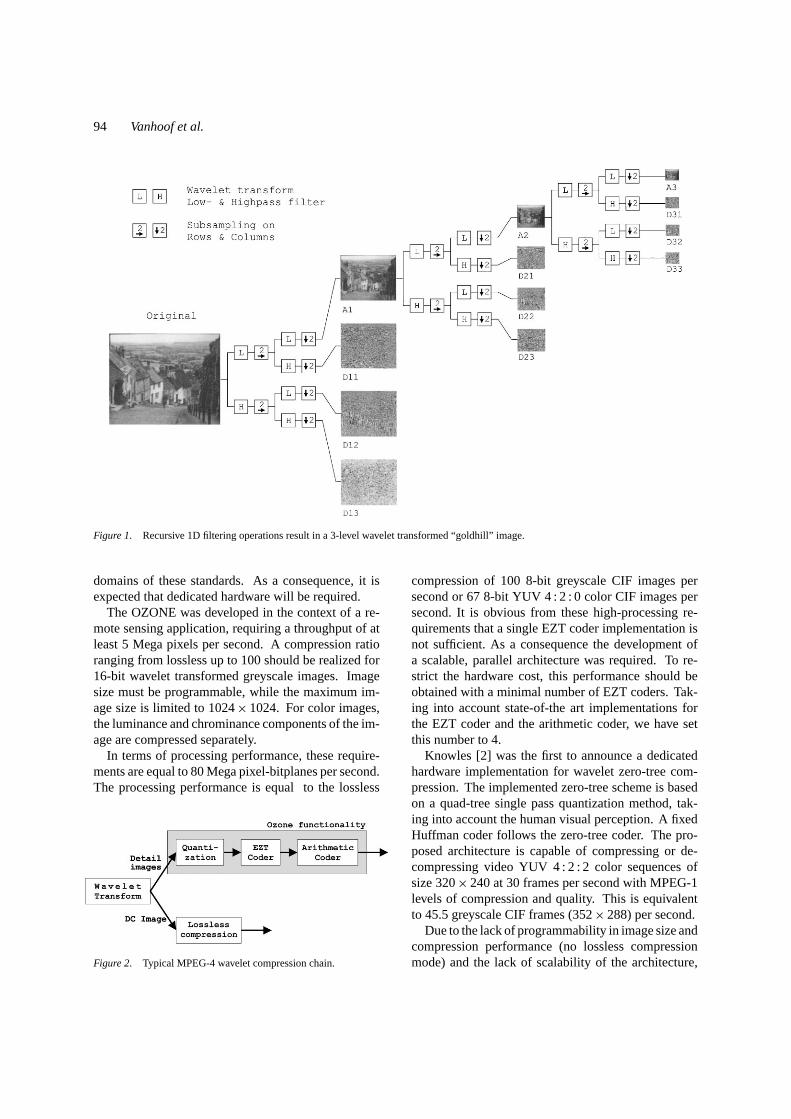
During wavelet transformation, the input image isdecomposed by successive 2D filtering and subsam-pling into an Average Image and Detail Images, asshown in Fig. 1. When separable filters are used, the2D filtering is performed by a horizontal and a verti-cal 1D convolution. The wavelet transformation is re-cursively executed on the lowpass filtered image fromeach level. Due to its recursive nature, the wavelettransform provides automatically a set of scaled im-ages: each lowpass filtered image can be considered asa scaled version of the original image. Typically thelast Average image (i.e. A3 in Fig. 1) and the DetailImages are compressed separately. The Average Imageis losslessly compressed using a lossless JPEG basedcompression technique. The Detail Images are com-pressed using a zero-tree based compression approach.The Single Quantization (SQ) uses a single-pass ap-proximation scheme. The Multiple Quantization (MQ)uses a multi-pass approximation scheme. The Bi-levelQuantization (BQ) is a refinement of the MQ scheme,where successive approximation values are halved. Atypical MPEG-4 wavelet compression chain is shownin Fig. 2.
Minimal power dissipation and high throughput arecrucial for both the mobile and the high-end application
94 Vanhoof et al.
Figure 1. Recursive 1D filtering operations result in a 3-level wavelet transformed “goldhill” image.
domains of these standards. As a consequence, it isexpected that dedicated hardware will be required.
The OZONE was developed in the context of a re-mote sensing application, requiring a throughput of atleast 5 Mega pixels per second. A compression ratioranging from lossless up to 100 should be realized for16-bit wavelet transformed greyscale images. Imagesize must be programmable, while the maximum im-age size is limited to 1024× 1024. For color images,the luminance and chrominance components of the im-age are compressed separately.
In terms of processing performance, these require-ments are equal to 80 Mega pixel-bitplanes per second.The processing performance is equal to the lossless
Figure 2. Typical MPEG-4 wavelet compression chain.
compression of 100 8-bit greyscale CIF images persecond or 67 8-bit YUV4 : 2 : 0color CIF images persecond. It is obvious from these high-processing re-quirements that a single EZT coder implementation isnot sufficient. As a consequence the development ofa scalable, parallel architecture was required. To re-strict the hardware cost, this performance should beobtained with a minimal number of EZT coders. Tak-ing into account state-of-the art implementations forthe EZT coder and the arithmetic coder, we have setthis number to 4.
Knowles [2] was the first to announce a dedicatedhardware implementation for wavelet zero-tree com-pression. The implemented zero-tree scheme is basedon a quad-tree single pass quantization method, tak-ing into account the human visual perception. A fixedHuffman coder follows the zero-tree coder. The pro-posed architecture is capable of compressing or de-compressing video YUV4 : 2 : 2 color sequences ofsize 320× 240 at 30 frames per second with MPEG-1levels of compression and quality. This is equivalentto 45.5 greyscale CIF frames (352× 288) per second.
Due to the lack of programmability in image size andcompression performance (no lossless compressionmode) and the lack of scalability of the architecture,
Scalable Architecture for MPEG-4 Wavelet Quantization 95
this solution does not fit our requirements. The codingscheme we present in the OZONE [3] uses a similarsuccessive approximation method as the BQ schemeproposed by Shapiro [4, 5], followed by an adaptivearithmetic coder.
The implementation of an EZT coder and the pre-ceding wavelet transform can not be considered inde-pendently from a global optimization point of view. Itis indeed not sufficient to minimize the hardware forthe wavelet transformation as proposed in the Recur-sive Pyramid Algorithm by Vishwanath [6, 7]. Thereis no guarantee for a good behavioral match betweenthe wavelet transform and the EZT coder, causing animpediment on the overall system memory sizes andaccesses. The Local Wavelet Transform [8, 9] cir-cumvents this problem by producing clusters of thewavelet transformed image directly consumed by theEZT coder. The proposed OZONE architecture takesthis constraint into account, leading to adaptations tothe original Shapiro EZT implementation.
Furthermore, the adaptive arithmetic coder is sim-plified by the use of a binary alphabet [10]. Most ofthe literature focuses in fast implementation of the en-coder stage, based on removing multiplications and di-visions [11, 12] or by approximating the probabilities[10, 13].
The Arithmetic Coder design, presented in [14],presents a VLSI design of an adaptive binary arithmeticcoder using a high-order Markov estimation model.Encoding and decoding operations are performed half-duplex in the same chip. The encoder stage is division-free and a simplified multiplier is used. A 10th-ordercontext Markov model is implemented for the predic-tion of the probabilities. In order to avoid storing allthe contexts, an algorithm that calculates part of theprobabilities on line is used. This reduces the hard-ware cost at expense of an increase in the processinglatency: 8.5 cycles are needed for encoding a symbol.
The performance of the design is 3 Mbit/s on av-erage at 25 MHz. Assuming a lossless compressionratio of 2, the arithmetic coder must be capable ofprocessing 10 Mbits/s (= number of pixels× numberof bitplanes/(compression ratio× number of parallelOZONEs)). Operating at 32 MHz, the arithmetic coderin the OZONE processes 10 Mbit/s.
In Section 2 the OZONE algorithm and the systemlevel optimizations applied to obtain an efficient andscalable architecture are described. The OZONE ar-chitecture is presented in Section 3. In Section 4 ourimplementation is compared to the MPEG-4 standard.
Section 5 discusses the applied design methodology.The performance results are summarized in Section 6.
2. OZONE Algorithm
The compression functionality for the detail images,indicated in the shaded box in Fig. 2, is implementedin the OZONE. This functionality includes power of2 quantization, EZT encoding and arithmetic coding.The OZONE takes the wavelet coefficients of a trans-formed image and produces a byte oriented compressedoutput stream. Programmability of the quantizationlevels for each wavelet subimage individually and thenumber of wavelet transformation levels allow a flexi-ble compression of different images.
2.1. The EZT Coder
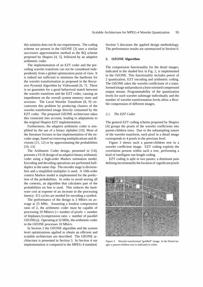
The general EZT coding scheme proposed by Shapiro[4] groups the pixels of the wavelet coefficients intoparent-children trees. Due to the subsampling natureof the wavelet transform, each pixel in a detail imagecorresponds to 4 pixels in the previous level.
Figure 3 shows such a parent-children tree in awavelet coefficient image. EZT coding exploits thecorrelation present within such a tree, performing akind of intelligent run-length coding.
EZT coding is split in two passes: a dominant passdefining incrementally the location of significant pixels
Figure 3. Wavelet transformed “goldhill” image. In the Detail im-ages a parent-children tree is indicated in white.
96 Vanhoof et al.
and a subordinate pass refining the pixel values for thealready significant pixels. All pixels are compared toa threshold value: if the absolute value exceeds thethreshold, the pixel is considered significant. The in-cremental definition of significant pixels is achieved bysuccessively dividing the threshold by two. During thedominant pass, 4 symbols are used: Zero Tree (ZT),Isolated Zero (IZ), Positive (POS) and Negative (NEG).The ZT symbol indicates a non-significant parent-children tree, i.e. all pixels in the parent-children treeare non-significant pixels. The IZ symbol indicates anon-significant pixel with at least one significant pixelpresent in its parent-children tree. The POS and NEGsymbols indicate a significant positive, respectivelynegative pixel. The subordinate pass uses 2 symbols:ZERO and ONE to indicate a significant zero and onebit respectively.
The general scheme [4] uses any integer value forthe threshold. A specific implementation proposed byShapiro [5], successively refines the wavelet coeffi-cients using a power of two threshold. This corres-ponds to a bitplane by bitplane approximation of thewavelet coefficients.
Since the classical Shapiro algorithm [4] recursivelyscans a complete image and requires a large amountof temporary memory, it is not suited for an efficienthardware implementation. The optimized Shapiro cod-ing scheme [5] reduces the number of accesses to thememories. The major bottleneck for a hardware im-plementation, i.e. the required amount of memory, ishowever not removed. As memory typically takes animportant part of the power budget in data-intensiveapplications [15], the memory size and the number ofmemory accesses should both be minimized for a low-power implementation.
Therefore we applied 5 different transformations toreduce both the memory size requirements, as well asthe number of memory accesses.
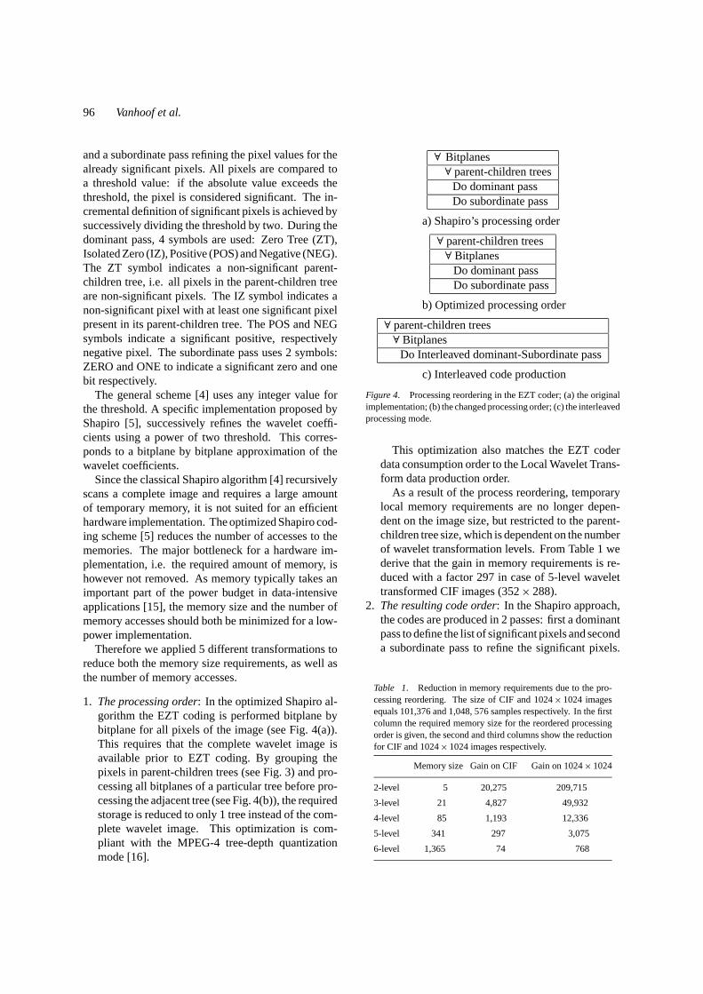
1. The processing order: In the optimized Shapiro al-gorithm the EZT coding is performed bitplane bybitplane for all pixels of the image (see Fig. 4(a)).This requires that the complete wavelet image isavailable prior to EZT coding. By grouping thepixels in parent-children trees (see Fig. 3) and pro-cessing all bitplanes of a particular tree before pro-cessing the adjacent tree (see Fig. 4(b)), the requiredstorage is reduced to only 1 tree instead of the com-plete wavelet image. This optimization is com-pliant with the MPEG-4 tree-depth quantizationmode [16].
∀ Bitplanes∀ parent-children trees
Do dominant passDo subordinate pass
a) Shapiro’s processing order
∀ parent-children trees∀ Bitplanes
Do dominant passDo subordinate pass
b) Optimized processing order
∀ parent-children trees∀ Bitplanes
Do Interleaved dominant-Subordinate pass
c) Interleaved code production
Figure 4. Processing reordering in the EZT coder; (a) the originalimplementation; (b) the changed processing order; (c) the interleavedprocessing mode.
This optimization also matches the EZT coderdata consumption order to the Local Wavelet Trans-form data production order.
As a result of the process reordering, temporarylocal memory requirements are no longer depen-dent on the image size, but restricted to the parent-children tree size, which is dependent on the numberof wavelet transformation levels. From Table 1 wederive that the gain in memory requirements is re-duced with a factor 297 in case of 5-level wavelettransformed CIF images (352× 288).
2. The resulting code order: In the Shapiro approach,the codes are produced in 2 passes: first a dominantpass to define the list of significant pixels and seconda subordinate pass to refine the significant pixels.
Table 1. Reduction in memory requirements due to the pro-cessing reordering. The size of CIF and 1024× 1024 imagesequals 101,376 and 1,048, 576 samples respectively. In the firstcolumn the required memory size for the reordered processingorder is given, the second and third columns show the reductionfor CIF and 1024× 1024 images respectively.
Memory size Gain on CIF Gain on 1024× 1024
2-level 5 20,275 209,715
3-level 21 4,827 49,932
4-level 85 1,193 12,336
5-level 341 297 3,075
6-level 1,365 74 768
Scalable Architecture for MPEG-4 Wavelet Quantization 97
Table 2. Number of read memory accesses for the dominantand the subordinate pass based on goldhill (352× 288) in case of5-level lossless compression. Accesses in the main loop of theEZT algorithm are not counted, as they only include initializationof the input image and the temporary arrays (Temp1 and Temp2).
Variable Separate Interleaved
InputImage 2,010,731 1,099,238
Temp1 2,328,475 1,416,982
Temp2 1,774,486 1,774,486
Total 6,113,692 4,290,706
These two passes can be combined into one singlepass producing both codes (see Fig. 4(c)).
As a result, the read accesses in both passes canbe shared. Table 2 summarizes the access countsfor the separate and the Interleaved Dominant-Subordinate pass. From this table we derive thatthe number of read accesses is reduced with30%.
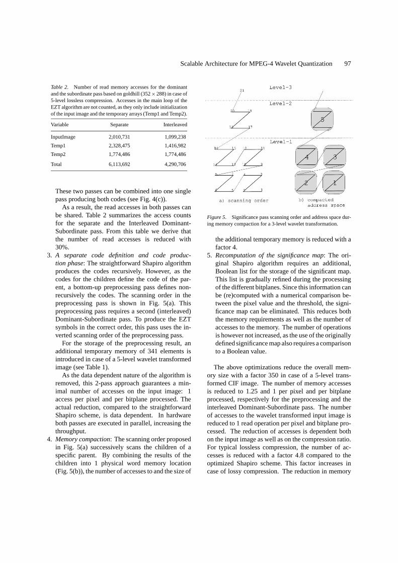
3. A separate code definition and code produc-tion phase: The straightforward Shapiro algorithmproduces the codes recursively. However, as thecodes for the children define the code of the par-ent, a bottom-up preprocessing pass defines non-recursively the codes. The scanning order in thepreprocessing pass is shown in Fig. 5(a). Thispreprocessing pass requires a second (interleaved)Dominant-Subordinate pass. To produce the EZTsymbols in the correct order, this pass uses the in-verted scanning order of the preprocessing pass.
For the storage of the preprocessing result, anadditional temporary memory of 341 elements isintroduced in case of a 5-level wavelet transformedimage (see Table 1).
As the data dependent nature of the algorithm isremoved, this 2-pass approach guarantees a min-imal number of accesses on the input image: 1access per pixel and per bitplane processed. Theactual reduction, compared to the straightforwardShapiro scheme, is data dependent. In hardwareboth passes are executed in parallel, increasing thethroughput.
4. Memory compaction: The scanning order proposedin Fig. 5(a) successively scans the children of aspecific parent. By combining the results of thechildren into 1 physical word memory location(Fig. 5(b)), the number of accesses to and the size of
Figure 5. Significance pass scanning order and address space dur-ing memory compaction for a 3-level wavelet transformation.
the additional temporary memory is reduced with afactor 4.
5. Recomputation of the significance map: The ori-ginal Shapiro algorithm requires an additional,Boolean list for the storage of the significant map.This list is gradually refined during the processingof the different bitplanes. Since this information canbe (re)computed with a numerical comparison be-tween the pixel value and the threshold, the signi-ficance map can be eliminated. This reduces boththe memory requirements as well as the number ofaccesses to the memory. The number of operationsis however not increased, as the use of the originallydefined significance map also requires a comparisonto a Boolean value.
The above optimizations reduce the overall mem-ory size with a factor 350 in case of a 5-level trans-formed CIF image. The number of memory accessesis reduced to 1.25 and 1 per pixel and per bitplaneprocessed, respectively for the preprocessing and theinterleaved Dominant-Subordinate pass. The numberof accesses to the wavelet transformed input image isreduced to 1 read operation per pixel and bitplane pro-cessed. The reduction of accesses is dependent bothon the input image as well as on the compression ratio.For typical lossless compression, the number of ac-cesses is reduced with a factor 4.8 compared to theoptimized Shapiro scheme. This factor increases incase of lossy compression. The reduction in memory
98 Vanhoof et al.
Table 3. The reduction in memory size and number of accesses obtained after eachof the transformation measured on “goldhill” (352× 288) in case of 5-level, losslesscompression. The reduction of the number of memory accesses is image dependent. (1st)and (2nd) refer to the first and the second phase respectively.
Memory size (in words) Number of memory accesses
Original implementation 3× 101,376= 304,128 7,329,115
After transform 1 3× 351= 1,053 7,329,115
After transform 2 3× 351= 1,053 5,506,129
After transform 3 3× 351= 1,053 4,341,578 (1st), 1,009,800 (2nd)
After transform 4 2× 351+ 85= 787 2,823,908 (1st), 252,450 (2nd)
After transform 5 351+ 85= 436 1,615,977 (1st), 252,450 (2nd)
size and the number of accesses is summarized inTable 3.
Due to the recomputation, the significance map iscorrectly defined for each bitplane, independent fromthe bitplane the EZT coding was started. This featureallows a scalable architecture by distributing clustersof the total range of bitplanes over multiple OZONEs.Due to different symbol statistics, a difference in com-pression performance is expected between a singleOZONE solution and a multiple OZONE configura-tion. In the case 4 OZONEs are operated in parallel aslight improvement in compression performance wasmeasured (see Table 4).
The two major advantages of the multiple OZONEconfiguration are the increased processing throughputand the generation of an SNR-scalable compressed bit-stream.
1. In case of an equal distribution of the processed bit-planes over the 4 parallel OZONEs, the throughputis increased with a factor 4.
Table 4. Compression results on the “goldhill” image (352× 288)in case of 5-level compression. The results are expressed as thenumber of bits present in the bitstream: the larger this number, thesmaller the compression ratio. Coding was started on bitplane 7 andstopped at the “Last bitplane processed”. “Last bitplane processed”= 0 represents lossless compression. This corresponds to 9 bit val-ues (sign+8 magnitude bits). The number of bitplanes processedby each of the 4 OZONEs is also indicated.
Last bitplane processed 1 OZONE 4 OZONEs Distribution
0 77,569 76,650 2-2-2-2
1 62,051 61,447 2-2-2-1
2 44,468 44,0474 2-2-1-1
3 26,669 26,329 2-1-1-1
4 11,745 11,691 1-1-1-1
2. The SNR scalable bitstream enables key MPEG-4functionality such as progressive transmission andgraceful degradation. The granularity of the dis-tributed clusters defines the granularity of the com-bined compressed bitstream.
2.2. The Arithmetic Coder
The resulting EZT symbols are passed to the arithmeticcoder for further entropy coding.
The EZT coder produces two different types of sym-bols: a dominant type creating four symbols (ZT, IZ,POS and NEG) and a subordinate pass with two sym-bols (ZERO and ONE). The fact of having two alpha-bets implies the use of two different arithmetic coders,one for each alphabet. Therefore, a first optimizationaims at decomposing the four-symbol alphabet into abinary one. This way, both alphabets are binary andonly one arithmetic coder is required. The conversionof the alphabet is done using Huffman coding. How-ever, the reduction into a binary alphabet produces ahigher number of binary symbols for encoding andconsequently the compression performance decreases,typically with 5–12% (see Table 5).
In order to compensate this loss of compression, dif-ferent options have been investigated [17].
One of the main important features from the arith-metic coder is the clear separation between the model,which estimates the probability for each input sym-bol and the encoding of the information with respectto this model (translates input symbols into a codedstream). Taking into account this fact, new statisticsmodels have been studied for improving the compres-sion performance.
1. The first possibility that has been analyzed is to ap-ply a first order Markov model that uses the previousencoded symbol to calculate the probability of the
Scalable Architecture for MPEG-4 Wavelet Quantization 99
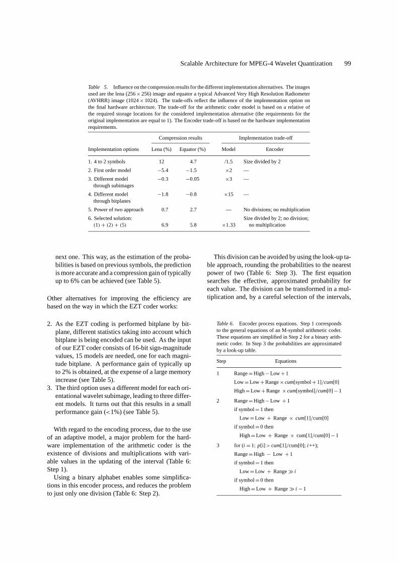
Table 5. Influence on the compression results for the different implementation alternatives. The imagesused are the lena (256× 256) image and equator a typical Advanced Very High Resolution Radiometer(AVHRR) image (1024× 1024). The trade-offs reflect the influence of the implementation option onthe final hardware architecture. The trade-off for the arithmetic coder model is based on a relative ofthe required storage locations for the considered implementation alternative (the requirements for theoriginal implementation are equal to 1). The Encoder trade-off is based on the hardware implementationrequirements.
Compression results Implementation trade-off
Implementation options Lena (%) Equator (%) Model Encoder
1. 4 to 2 symbols 12 4.7 /1.5 Size divided by 2
2. First order model −5.4 −1.5 ×2 —
3. Different model −0.3 −0.05 ×3 —through subimages
4. Different model −1.8 −0.8 ×15 —through bitplanes
5. Power of two approach 0.7 2.7 — No divisions; no multiplication
6. Selected solution: Size divided by 2; no division;(1)+ (2)+ (5) 6.9 5.8 ×1.33 no multiplication
next one. This way, as the estimation of the proba-bilities is based on previous symbols, the predictionis more accurate and a compression gain of typicallyup to 6% can be achieved (see Table 5).
Other alternatives for improving the efficiency arebased on the way in which the EZT coder works:
2. As the EZT coding is performed bitplane by bit-plane, different statistics taking into account whichbitplane is being encoded can be used. As the inputof our EZT coder consists of 16-bit sign-magnitudevalues, 15 models are needed, one for each magni-tude bitplane. A performance gain of typically upto 2% is obtained, at the expense of a large memoryincrease (see Table 5).
3. The third option uses a different model for each ori-entational wavelet subimage, leading to three differ-ent models. It turns out that this results in a smallperformance gain (<1%) (see Table 5).
With regard to the encoding process, due to the useof an adaptive model, a major problem for the hard-ware implementation of the arithmetic coder is theexistence of divisions and multiplications with vari-able values in the updating of the interval (Table 6:Step 1).
Using a binary alphabet enables some simplifica-tions in this encoder process, and reduces the problemto just only one division (Table 6: Step 2).
This division can be avoided by using the look-up ta-ble approach, rounding the probabilities to the nearestpower of two (Table 6: Step 3). The first equationsearches the effective, approximated probability foreach value. The division can be transformed in a mul-tiplication and, by a careful selection of the intervals,
Table 6. Encoder process equations. Step 1 correspondsto the general equations of an M-symbol arithmetic coder.These equations are simplified in Step 2 for a binary arith-metic coder. In Step 3 the probabilities are approximatedby a look-up table.
Step Equations
1 Range=High− Low+ 1
Low= Low+Range× cum[symbol+ 1]/cum[0]
High= Low+Range× cum[symbol]/cum[0]− 1
2 Range=High− Low + 1
if symbol= 1 then
Low= Low + Range× cum[1]/cum[0]
if symbol= 0 then
High= Low + Range× cum[1]/cum[0]− 1
3 for (i = 1; p[i] > cum[1]/cum[0]; i ++);
Range=High − Low + 1
if symbol= 1 then
Low= Low + RangeÀ i
if symbol= 0 then
High= Low + RangeÀ i − 1
100 Vanhoof et al.
the probability p[i ] can be expressed as:p[i ] =const× 215−i , as a result only one constant multipli-cation remains. This multiplication can be performedby right-shift operations [17]. This simplification inhardware complexity means a decrease of compressionperformance, typically up to 3% (see Table 5).
Taking into account the hardware requirements andthe compression results, (see Table 5) a programmableHuffman coder followed by an adaptive, first order, bi-nary arithmetic coder without multiplications or divi-sions has been selected. The loss in compression per-formance that is associated to this implementationaloptimization amounts up to approximately 7%.
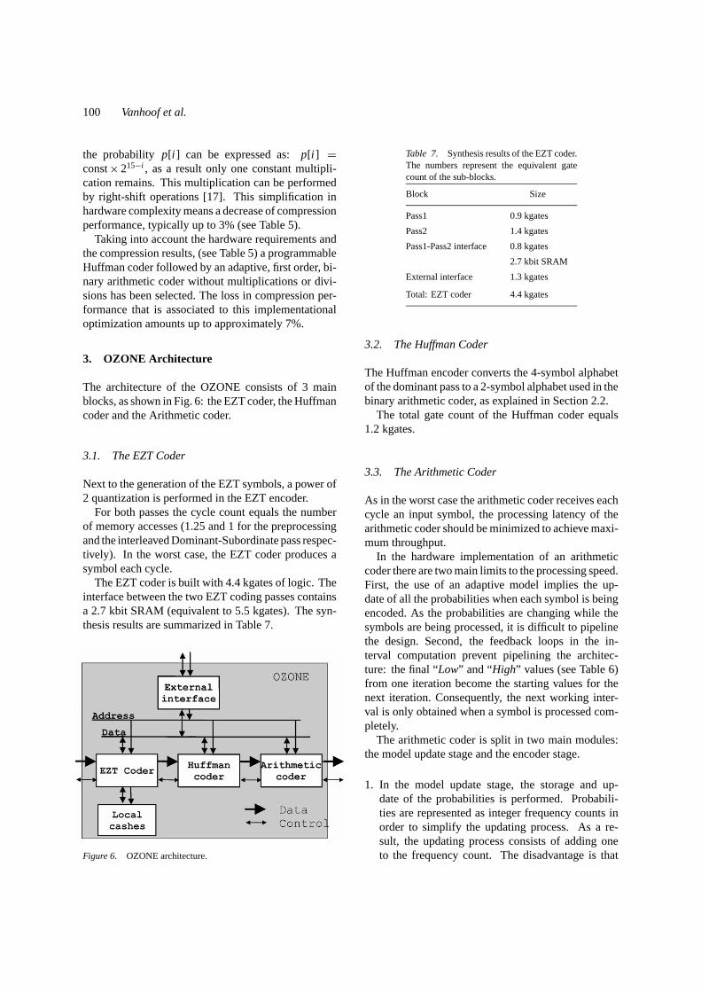
3. OZONE Architecture
The architecture of the OZONE consists of 3 mainblocks, as shown in Fig. 6: the EZT coder, the Huffmancoder and the Arithmetic coder.
3.1. The EZT Coder
Next to the generation of the EZT symbols, a power of2 quantization is performed in the EZT encoder.
For both passes the cycle count equals the numberof memory accesses (1.25 and 1 for the preprocessingand the interleaved Dominant-Subordinate pass respec-tively). In the worst case, the EZT coder produces asymbol each cycle.
The EZT coder is built with 4.4 kgates of logic. Theinterface between the two EZT coding passes containsa 2.7 kbit SRAM (equivalent to 5.5 kgates). The syn-thesis results are summarized in Table 7.
Figure 6. OZONE architecture.
Table 7. Synthesis results of the EZT coder.The numbers represent the equivalent gatecount of the sub-blocks.
Block Size
Pass1 0.9 kgates
Pass2 1.4 kgates
Pass1-Pass2 interface 0.8 kgates
2.7 kbit SRAM
External interface 1.3 kgates
Total: EZT coder 4.4 kgates
3.2. The Huffman Coder
The Huffman encoder converts the 4-symbol alphabetof the dominant pass to a 2-symbol alphabet used in thebinary arithmetic coder, as explained in Section 2.2.
The total gate count of the Huffman coder equals1.2 kgates.
3.3. The Arithmetic Coder
As in the worst case the arithmetic coder receives eachcycle an input symbol, the processing latency of thearithmetic coder should be minimized to achieve maxi-mum throughput.
In the hardware implementation of an arithmeticcoder there are two main limits to the processing speed.First, the use of an adaptive model implies the up-date of all the probabilities when each symbol is beingencoded. As the probabilities are changing while thesymbols are being processed, it is difficult to pipelinethe design. Second, the feedback loops in the in-terval computation prevent pipelining the architec-ture: the final “Low” and “High” values (see Table 6)from one iteration become the starting values for thenext iteration. Consequently, the next working inter-val is only obtained when a symbol is processed com-pletely.
The arithmetic coder is split in two main modules:the model update stage and the encoder stage.
1. In the model update stage, the storage and up-date of the probabilities is performed. Probabili-ties are represented as integer frequency counts inorder to simplify the updating process. As a re-sult, the updating process consists of adding oneto the frequency count. The disadvantage is that
Scalable Architecture for MPEG-4 Wavelet Quantization 101
the cumulative frequency counts are also needed forcomputing the probabilities, increasing the memorycost. In this design unsigned 14 bit numbers rep-resents the frequency counts. The frequencies andcumulative frequencies for both models require 224bits in total and can be stored directly into hardwareregisters. This block requires on average 1 cycleper input symbol.
2. In the encoder stage, the output bits are generatedand the interval is updated. These two tasks havefeedback loops and data dependent iterations thatprevent speeding up the design.This block is the bottleneck in terms of processinglatency. A detailed study about the number of iter-ations executed in each loop shows which transfor-mation techniques to apply to speed up the design.Unrolling and merging techniques combined withlook ahead transformations [18] reduce the averagenumber of cycles for the encoder stage to 2.
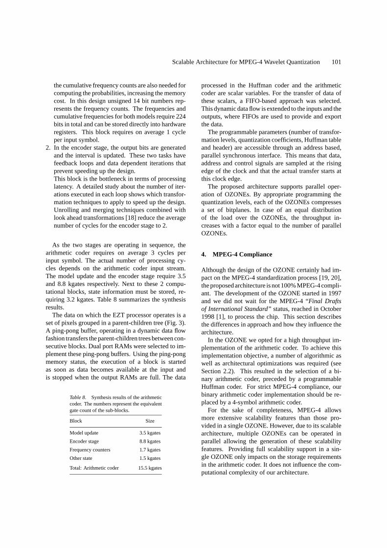
As the two stages are operating in sequence, thearithmetic coder requires on average 3 cycles perinput symbol. The actual number of processing cy-cles depends on the arithmetic coder input stream.The model update and the encoder stage require 3.5and 8.8 kgates respectively. Next to these 2 compu-tational blocks, state information must be stored, re-quiring 3.2 kgates. Table 8 summarizes the synthesisresults.
The data on which the EZT processor operates is aset of pixels grouped in a parent-children tree (Fig. 3).A ping-pong buffer, operating in a dynamic data flowfashion transfers the parent-children trees between con-secutive blocks. Dual port RAMs were selected to im-plement these ping-pong buffers. Using the ping-pongmemory status, the execution of a block is startedas soon as data becomes available at the input andis stopped when the output RAMs are full. The data
Table 8. Synthesis results of the arithmeticcoder. The numbers represent the equivalentgate count of the sub-blocks.
Block Size
Model update 3.5 kgates
Encoder stage 8.8 kgates
Frequency counters 1.7 kgates
Other state 1.5 kgates
Total: Arithmetic coder 15.5 kgates
processed in the Huffman coder and the arithmeticcoder are scalar variables. For the transfer of data ofthese scalars, a FIFO-based approach was selected.This dynamic data flow is extended to the inputs and theoutputs, where FIFOs are used to provide and exportthe data.
The programmable parameters (number of transfor-mation levels, quantization coefficients, Huffman tableand header) are accessible through an address based,parallel synchronous interface. This means that data,address and control signals are sampled at the risingedge of the clock and that the actual transfer starts atthis clock edge.
The proposed architecture supports parallel oper-ation of OZONEs. By appropriate programming thequantization levels, each of the OZONEs compressesa set of bitplanes. In case of an equal distributionof the load over the OZONEs, the throughput in-creases with a factor equal to the number of parallelOZONEs.
4. MPEG-4 Compliance
Although the design of the OZONE certainly had im-pact on the MPEG-4 standardization process [19, 20],the proposed architecture is not 100% MPEG-4 compli-ant. The development of the OZONE started in 1997and we did not wait for the MPEG-4 “Final Draftsof International Standard” status, reached in October1998 [1], to process the chip. This section describesthe differences in approach and how they influence thearchitecture.
In the OZONE we opted for a high throughput im-plementation of the arithmetic coder. To achieve thisimplementation objective, a number of algorithmic aswell as architectural optimizations was required (seeSection 2.2). This resulted in the selection of a bi-nary arithmetic coder, preceded by a programmableHuffman coder. For strict MPEG-4 compliance, ourbinary arithmetic coder implementation should be re-placed by a 4-symbol arithmetic coder.
For the sake of completeness, MPEG-4 allowsmore extensive scalability features than those pro-vided in a single OZONE. However, due to its scalablearchitecture, multiple OZONEs can be operated inparallel allowing the generation of these scalabilityfeatures. Providing full scalability support in a sin-gle OZONE only impacts on the storage requirementsin the arithmetic coder. It does not influence the com-putational complexity of our architecture.
102 Vanhoof et al.
5. Design Methodology
In order to achieve a significant decrease of the actualpower dissipation and a high processing throughputfor a given application, both the number of accesses aswell as the memory size must be minimized. Indeed,the number of memory accesses limits the processingthroughput: in a single port memory each access cor-responds to a cycle. As a consequence the number ofaccesses to a memory is the lower limit for the numberof cycles the algorithm is executing on an (application-specific) processor. Moreover, the storage and thetransfers to memory heavily dominate the power dis-sipation in real-time image processing applications[21, 22]. The power dissipation is proportional to theaccess frequency and capacitive load of the mem-ory [15].
The minimization of the number of transfers andthe dissipated power is achieved using a memory andtransfer organization with the following characteristics:
1. Reduce the redundancy in data transfers.2. Introduce more locality in the accesses so that more
data can be retained in registers local to the data-paths.
3. Use a hierarchical memory organization where thesmaller memories (with reduced capacitive load) areaccessed the most and the larger ones are accessedthe least.
4. Avoid the use of N-port memories if 1-port alter-natives with a reasonable cost can be used instead,because more area but also more interconnect (andhence energy-delay) is required for the multi-portcomponents.
These characteristics are applied in the ATOMIUMdesign methodology [15].
The EZT encoder was optimized using this designmethodology. First the critical memory bottleneckswere located using the ATOMIUM memory accesscounting classes. Second, the original algorithm wastransformed using the transformation methodology ofATOMIUM (as explained in Section 2.1).
The OZONE, based on the optimized EZT encoderand including the arithmetic coder, was designed us-ing a C++ based design strategy called OCAPI [23].The OCAPI design environment allows for fast highlevel modeling and simulation of the hardware im-plementation. This enables an extended design spaceexploration. Once the optimal solution is identified,
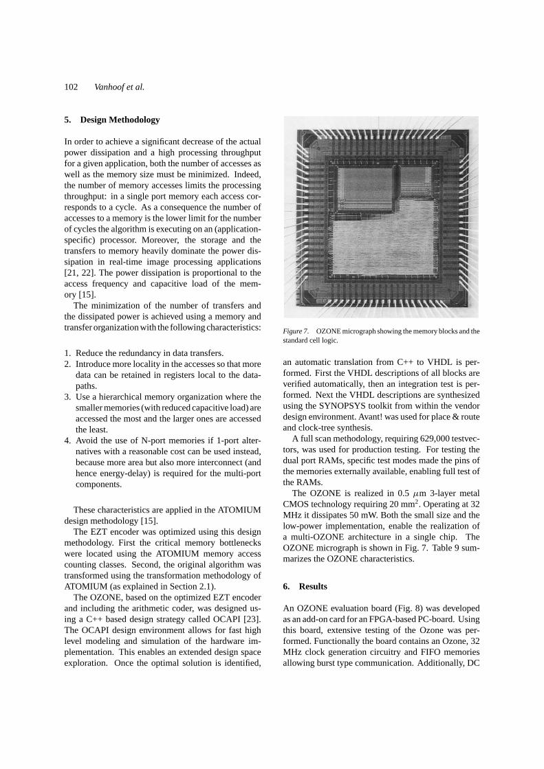
Figure 7. OZONE micrograph showing the memory blocks and thestandard cell logic.
an automatic translation from C++ to VHDL is per-formed. First the VHDL descriptions of all blocks areverified automatically, then an integration test is per-formed. Next the VHDL descriptions are synthesizedusing the SYNOPSYS toolkit from within the vendordesign environment. Avant! was used for place & routeand clock-tree synthesis.
A full scan methodology, requiring 629,000 testvec-tors, was used for production testing. For testing thedual port RAMs, specific test modes made the pins ofthe memories externally available, enabling full test ofthe RAMs.
The OZONE is realized in 0.5µm 3-layer metalCMOS technology requiring 20 mm2. Operating at 32MHz it dissipates 50 mW. Both the small size and thelow-power implementation, enable the realization ofa multi-OZONE architecture in a single chip. TheOZONE micrograph is shown in Fig. 7. Table 9 sum-marizes the OZONE characteristics.
6. Results
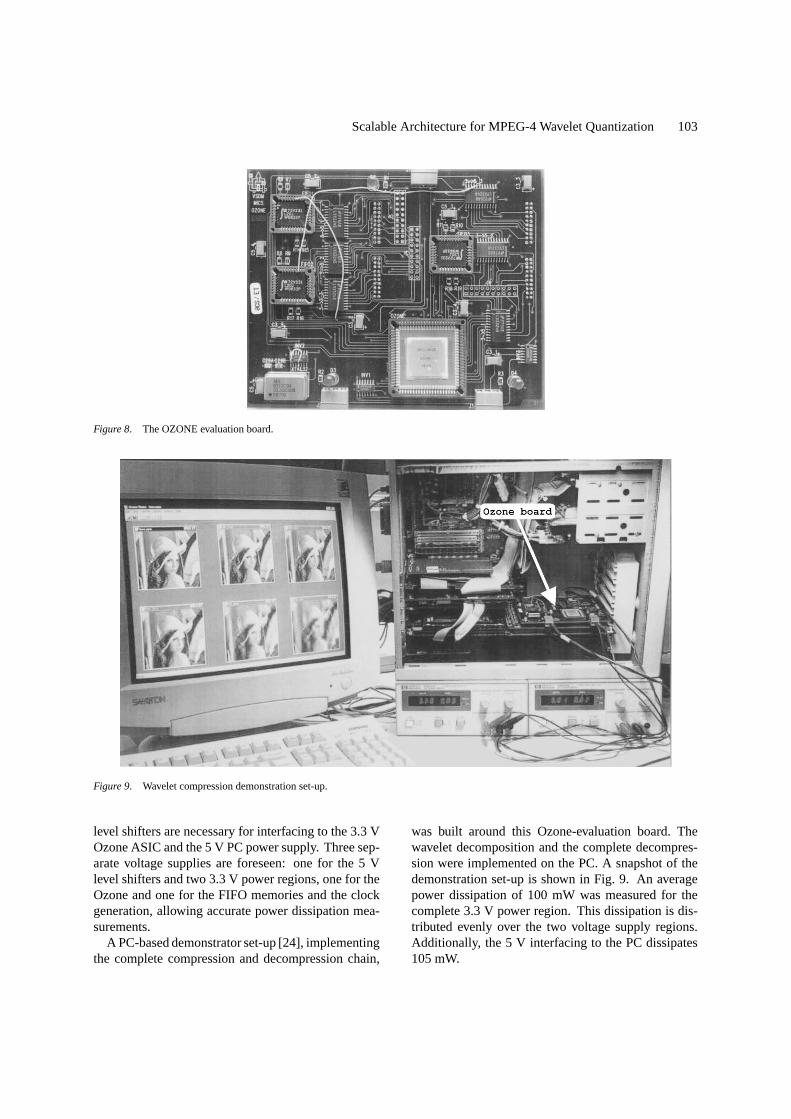
An OZONE evaluation board (Fig. 8) was developedas an add-on card for an FPGA-based PC-board. Usingthis board, extensive testing of the Ozone was per-formed. Functionally the board contains an Ozone, 32MHz clock generation circuitry and FIFO memoriesallowing burst type communication. Additionally, DC
Scalable Architecture for MPEG-4 Wavelet Quantization 103
Figure 8. The OZONE evaluation board.
Figure 9. Wavelet compression demonstration set-up.
level shifters are necessary for interfacing to the 3.3 VOzone ASIC and the 5 V PC powersupply. Three sep-arate voltage supplies are foreseen: one for the 5 Vlevel shifters and two 3.3 V power regions, one for theOzone and one for the FIFO memories and the clockgeneration, allowing accurate power dissipation mea-surements.
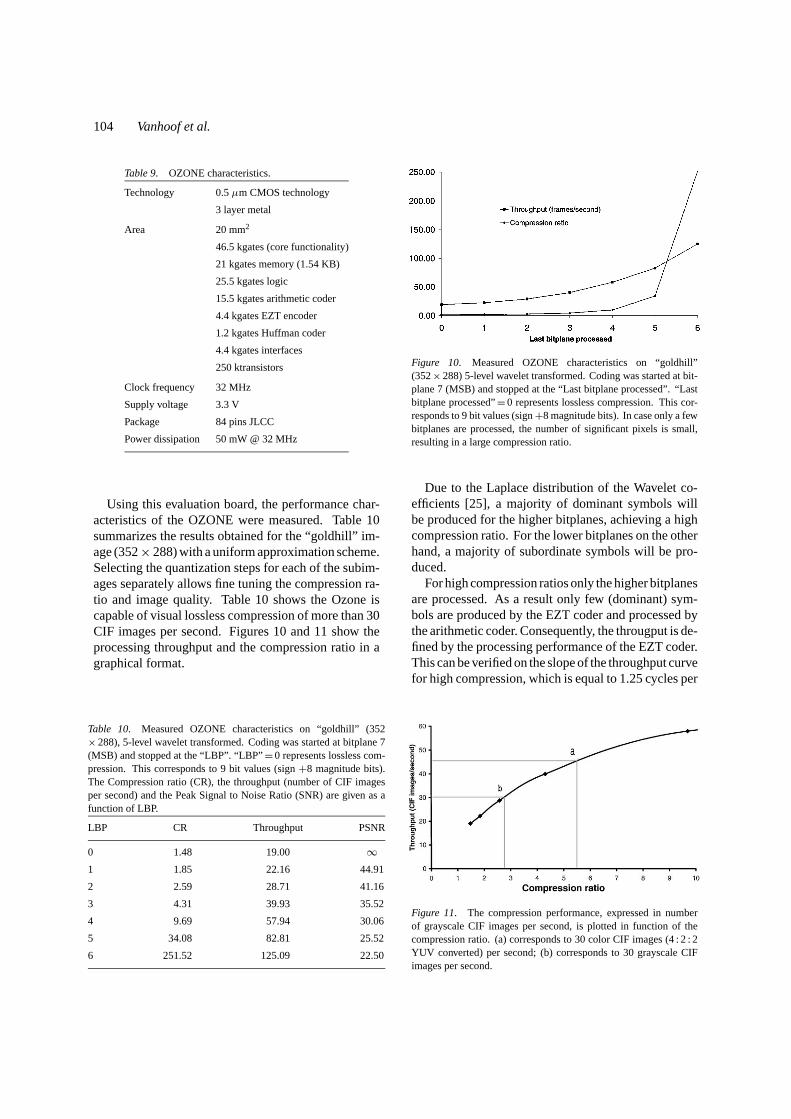
A PC-based demonstrator set-up [24], implementingthe complete compression and decompression chain,
was built around this Ozone-evaluation board. Thewavelet decomposition and the complete decompres-sion were implemented on the PC. A snapshot of thedemonstration set-up is shown in Fig. 9. An averagepower dissipation of 100 mW was measured for thecomplete 3.3 V power region. This dissipation is dis-tributed evenly over the two voltage supply regions.Additionally, the 5 V interfacing to the PC dissipates105 mW.
104 Vanhoof et al.
Table 9. OZONE characteristics.
Technology 0.5µm CMOS technology
3 layer metal
Area 20 mm2
46.5 kgates (core functionality)
21 kgates memory (1.54 KB)
25.5 kgates logic
15.5 kgates arithmetic coder
4.4 kgates EZT encoder
1.2 kgates Huffman coder
4.4 kgates interfaces
250 ktransistors
Clock frequency 32 MHz
Supply voltage 3.3 V
Package 84 pins JLCC
Power dissipation 50 mW @ 32 MHz
Using this evaluation board, the performance char-acteristics of the OZONE were measured. Table 10summarizes the results obtained for the “goldhill” im-age (352× 288) with a uniform approximation scheme.Selecting the quantization steps for each of the subim-ages separately allows fine tuning the compression ra-tio and image quality. Table 10 shows the Ozone iscapable of visual lossless compression of more than 30CIF images per second. Figures 10 and 11 show theprocessing throughput and the compression ratio in agraphical format.
Table 10. Measured OZONE characteristics on “goldhill” (352× 288), 5-level wavelet transformed. Coding was started at bitplane 7(MSB) and stopped at the “LBP”. “LBP”= 0 represents lossless com-pression. This corresponds to 9 bit values (sign+8 magnitude bits).The Compression ratio (CR), the throughput (number of CIF imagesper second) and the Peak Signal to Noise Ratio (SNR) are given as afunction of LBP.
LBP CR Throughput PSNR
0 1.48 19.00 ∞1 1.85 22.16 44.91
2 2.59 28.71 41.16
3 4.31 39.93 35.52
4 9.69 57.94 30.06
5 34.08 82.81 25.52
6 251.52 125.09 22.50
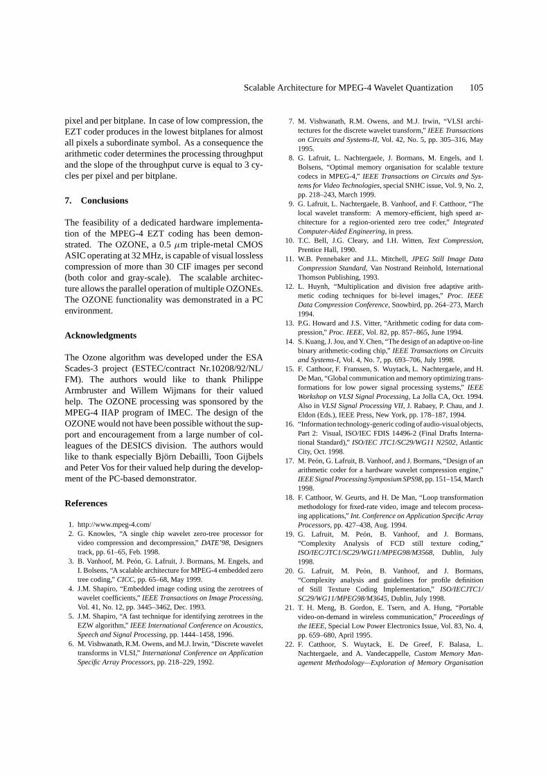
Figure 10. Measured OZONE characteristics on “goldhill”(352× 288) 5-level wavelet transformed. Coding was started at bit-plane 7 (MSB) and stopped at the “Last bitplane processed”. “Lastbitplane processed”= 0 represents lossless compression. This cor-responds to 9 bit values (sign+8 magnitude bits). In case only a fewbitplanes are processed, the number of significant pixels is small,resulting in a large compression ratio.
Due to the Laplace distribution of the Wavelet co-efficients [25], a majority of dominant symbols willbe produced for the higher bitplanes, achieving a highcompression ratio. For the lower bitplanes on the otherhand, a majority of subordinate symbols will be pro-duced.
For high compression ratios only the higher bitplanesare processed. As a result only few (dominant) sym-bols are produced by the EZT coder and processed bythe arithmetic coder. Consequently, the througput is de-fined by the processing performance of the EZT coder.This can be verified on the slope of the throughput curvefor high compression, which is equal to 1.25 cycles per
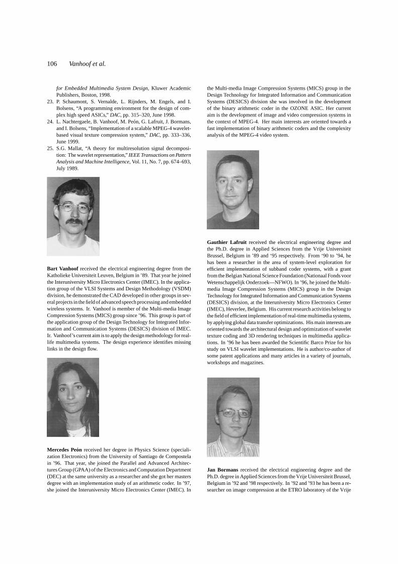
Figure 11. The compression performance, expressed in numberof grayscale CIF images per second, is plotted in function of thecompression ratio. (a) corresponds to 30 color CIF images (4 : 2 : 2YUV converted) per second; (b) corresponds to 30 grayscale CIFimages per second.
Scalable Architecture for MPEG-4 Wavelet Quantization 105
pixel and per bitplane. In case of low compression, theEZT coder produces in the lowest bitplanes for almostall pixels a subordinate symbol. As a consequence thearithmetic coder determines the processing throughputand the slope of the throughput curve is equal to 3 cy-cles per pixel and per bitplane.
7. Conclusions
The feasibility of a dedicated hardware implementa-tion of the MPEG-4 EZT coding has been demon-strated. The OZONE, a 0.5µm triple-metal CMOSASIC operating at 32 MHz, is capable of visual losslesscompression of more than 30 CIF images per second(both color and gray-scale). The scalable architec-ture allows the parallel operation of multiple OZONEs.The OZONE functionality was demonstrated in a PCenvironment.
Acknowledgments
The Ozone algorithm was developed under the ESAScades-3 project (ESTEC/contract Nr.10208/92/NL/FM). The authors would like to thank PhilippeArmbruster and Willem Wijmans for their valuedhelp. The OZONE processing was sponsored by theMPEG-4 IIAP program of IMEC. The design of theOZONE would not have been possible without the sup-port and encouragement from a large number of col-leagues of the DESICS division. The authors wouldlike to thank especially Bj¨orn Debailli, Toon Gijbelsand Peter Vos for their valued help during the develop-ment of the PC-based demonstrator.
References
1. http://www.mpeg-4.com/2. G. Knowles, “A single chip wavelet zero-tree processor for
video compression and decompression,”DATE’98, Designerstrack, pp. 61–65, Feb. 1998.
3. B. Vanhoof, M. Pe´on, G. Lafruit, J. Bormans, M. Engels, andI. Bolsens, “A scalable architecture for MPEG-4 embedded zerotree coding,”CICC, pp. 65–68, May 1999.
4. J.M. Shapiro, “Embedded image coding using the zerotrees ofwavelet coefficients,”IEEE Transactions on Image Processing,Vol. 41, No. 12, pp. 3445–3462, Dec. 1993.
5. J.M. Shapiro, “A fast technique for identifying zerotrees in theEZW algorithm,”IEEE International Conference on Acoustics,Speech and Signal Processing, pp. 1444–1458, 1996.
6. M. Vishwanath, R.M. Owens, and M.J. Irwin, “Discrete wavelettransforms in VLSI,”International Conference on ApplicationSpecific Array Processors, pp. 218–229, 1992.
7. M. Vishwanath, R.M. Owens, and M.J. Irwin, “VLSI archi-tectures for the discrete wavelet transform,”IEEE Transactionson Circuits and Systems-II, Vol. 42, No. 5, pp. 305–316, May1995.
8. G. Lafruit, L. Nachtergaele, J. Bormans, M. Engels, and I.Bolsens, “Optimal memory organisation for scalable texturecodecs in MPEG-4,”IEEE Transactions on Circuits and Sys-tems for Video Technologies, special SNHC issue, Vol. 9, No. 2,pp. 218–243, March 1999.
9. G. Lafruit, L. Nachtergaele, B. Vanhoof, and F. Catthoor, “Thelocal wavelet transform: A memory-efficient, high speed ar-chitecture for a region-oriented zero tree coder,”IntegratedComputer-Aided Engineering, in press.
10. T.C. Bell, J.G. Cleary, and I.H. Witten,Text Compression,Prentice Hall, 1990.
11. W.B. Pennebaker and J.L. Mitchell,JPEG Still Image DataCompression Standard, Van Nostrand Reinhold, InternationalThomson Publishing, 1993.
12. L. Huynh, “Multiplication and division free adaptive arith-metic coding techniques for bi-level images,”Proc. IEEEData Compression Conference, Snowbird, pp. 264–273, March1994.
13. P.G. Howard and J.S. Vitter, “Arithmetic coding for data com-pression,”Proc. IEEE, Vol. 82, pp. 857–865, June 1994.
14. S. Kuang, J. Jou, and Y. Chen, “The design of an adaptive on-linebinary arithmetic-coding chip,”IEEE Transactions on Circuitsand Systems-I, Vol. 4, No. 7, pp. 693–706, July 1998.
15. F. Catthoor, F. Franssen, S. Wuytack, L. Nachtergaele, and H.De Man, “Global communication and memory optimizing trans-formations for low power signal processing systems,”IEEEWorkshop on VLSI Signal Processing, La Jolla CA, Oct. 1994.Also in VLSI Signal Processing VII, J. Rabaey, P. Chau, and J.Eldon (Eds.), IEEE Press, New York, pp. 178–187, 1994.
16. “Information technology-generic coding of audio-visual objects,Part 2: Visual, ISO/IEC FDIS 14496-2 (Final Drafts Interna-tional Standard),”ISO/IEC JTC1/SC29/WG11 N2502, AtlanticCity, Oct. 1998.
17. M. Peon, G. Lafruit, B. Vanhoof, and J. Bormans, “Design of anarithmetic coder for a hardware wavelet compression engine,”IEEE Signal Processing Symposium SPS98, pp. 151–154, March1998.
18. F. Catthoor, W. Geurts, and H. De Man, “Loop transformationmethodology for fixed-rate video, image and telecom process-ing applications,”Int. Conference on Application Specific ArrayProcessors, pp. 427–438, Aug. 1994.
19. G. Lafruit, M. Pe´on, B. Vanhoof, and J. Bormans,“Complexity Analysis of FCD still texture coding,”ISO/IEC/JTC1/SC29/WG11/MPEG98/M3568, Dublin, July1998.
20. G. Lafruit, M. Pe´on, B. Vanhoof, and J. Bormans,“Complexity analysis and guidelines for profile definitionof Still Texture Coding Implementation,”ISO/IECJTC1/SC29/WG11/MPEG98/M3645, Dublin, July 1998.
21. T. H. Meng, B. Gordon, E. Tsern, and A. Hung, “Portablevideo-on-demand in wireless communication,”Proceedings ofthe IEEE, Special Low Power Electronics Issue, Vol. 83, No. 4,pp. 659–680, April 1995.
22. F. Catthoor, S. Wuytack, E. De Greef, F. Balasa, L.Nachtergaele, and A. Vandecappelle,Custom Memory Man-agement Methodology—Exploration of Memory Organisation
106 Vanhoof et al.
for Embedded Multimedia System Design, Kluwer AcademicPublishers, Boston, 1998.
23. P. Schaumont, S. Vernalde, L. Rijnders, M. Engels, and I.Bolsens, “A programming environment for the design of com-plex high speed ASICs,”DAC, pp. 315–320, June 1998.
24. L. Nachtergaele, B. Vanhoof, M. Pe´on, G. Lafruit, J. Bormans,and I. Bolsens, “Implementation of a scalable MPEG-4 wavelet-based visual texture compression system,”DAC, pp. 333–336,June 1999.
25. S.G. Mallat, “A theory for multiresolution signal decomposi-tion: The wavelet representation,”IEEE Transactions on PatternAnalysis and Machine Intelligence, Vol. 11, No. 7, pp. 674–693,July 1989.
Bart Vanhoof received the electrical engineering degree from theKatholieke Universiteit Leuven, Belgium in ’89. That year he joinedthe Interuniversity Micro Electronics Center (IMEC). In the applica-tion group of the VLSI Systems and Design Methodology (VSDM)division, he demonstrated the CAD developed in other groups in sev-eral projects in the field of advanced speech processing and embeddedwireless systems. Ir. Vanhoof is member of the Multi-media ImageCompression Systems (MICS) group since ’96. This group is part ofthe application group of the Design Technology for Integrated Infor-mation and Communication Systems (DESICS) division of IMEC.Ir. Vanhoof’s current aim is to apply the design methodology for real-life multimedia systems. The design experience identifies missinglinks in the design flow.
Mercedes Pe´on received her degree in Physics Science (speciali-zation Electronics) from the University of Santiago de Compostelain ’96. That year, she joined the Parallel and Advanced Architec-tures Group (GPAA) of the Electronics and Computation Department(DEC) at the same university as a researcher and she got her mastersdegree with an implementation study of an arithmetic coder. In ’97,she joined the Interuniversity Micro Electronics Center (IMEC). In
the Multi-media Image Compression Systems (MICS) group in theDesign Technology for Integrated Information and CommunicationSystems (DESICS) division she was involved in the developmentof the binary arithmetic coder in the OZONE ASIC. Her currentaim is the development of image and video compression systems inthe context of MPEG-4. Her main interests are oriented towards afast implementation of binary arithmetic coders and the complexityanalysis of the MPEG-4 video system.
Gauthier Lafruit received the electrical engineering degree andthe Ph.D. degree in Applied Sciences from the Vrije UniversiteitBrussel, Belgium in ’89 and ‘95 respectively. From ‘90 to ’94, hehas been a researcher in the area of system-level exploration forefficient implementation of subband coder systems, with a grantfrom the Belgian National Science Foundation (Nationaal Fonds voorWetenschappelijk Onderzoek—NFWO). In ’96, he joined the Multi-media Image Compression Systems (MICS) group in the DesignTechnology for Integrated Information and Communication Systems(DESICS) division, at the Interuniversity Micro Electronics Center(IMEC), Heverlee, Belgium. His current research activities belong tothe field of efficient implementation of real-time multimedia systems,by applying global data transfer optimizations. His main interests areoriented towards the architectural design and optimization of wavelettexture coding and 3D rendering techniques in multimedia applica-tions. In ’96 he has been awarded the Scientific Barco Prize for hisstudy on VLSI wavelet implementations. He is author/co-author ofsome patent applications and many articles in a variety of journals,workshops and magazines.
Jan Bormans received the electrical engineering degree and thePh.D. degree in Applied Sciences from the Vrije Universiteit Brussel,Belgium in ’92 and ’98 respectively. In ’92 and ’93 he has been a re-searcher on image compression at the ETRO laboratory of the Vrije
Scalable Architecture for MPEG-4 Wavelet Quantization 107
Universiteit Brussel (VUB), Belgium. In ’94, he joined the VLSISystems and Design Methodologies (VSDM) division of the In-teruniversity Micro Electronics Center (IMEC) in Leuven, Belgium.Since ’96, he is heading the Multimedia Image Compression Systemsgroup in DESICS (Design Technology for Integrated Informationand Communication Systems), focusing on the efficient design andimplementation of systems-on-a-chip for advanced multimedia ap-plications. He is also the Belgian head of delegation for the ISO/IECMPEG standardization committee.
Lode Nachtergaelereceived his degree of Industrial Engineer in ’89from the Katholieke Hogeschool Oostende, Belgium. In the sameyear he joined The Interuniversity Micro Electronics Center (IMEC)starting his career in the group working on the Cathedral-II siliconcompiler. He was involved in the development of the Silage simu-lator S2C. In ’92 he joined the System Exploration for Memory andPower (SEMP) group. Together with his colleagues, he worked onthe ATOMIUM methodology, partially supported by prototype tools.In ’96 Ing. Nachtergaele joined the Multi-media Image CompressionSystems (MICS) of the Design Technology for Integrated Informa-tion and Communication Systems (DESICS) division of IMEC. In’99 he became the technical coordinator of the MICS group. He isalso the Belgian head of delegation for the ISO/IEC JPEG standardi-zation committee.
Ivo Bolsensreceived the Electrical Engineering and Ph.D. Degreefrom the Katholieke Universiteit Leuven, Belgium in ’81 and ’89respectively. Since ’81 he was a member of the CAD group at theESAT laboratory of the Katholieke Universiteit Leuven, where hewas working on the development of an electrical verification pro-gram for VLSI circuits and on mixed mode simulation. In ’84 hejoined the IMEC Laboratory, where he started doing research onthe development of knowledge based verification for VLSI circuits,exploiting methods in the domain of Artificial Intelligence. In thiscontext he introduced functional programming, using Lisp, and ob-ject oriented programming, using Smalltalk. In ’89 he became re-sponsible for the application and development of the Cathedral-2,and later the Cathedral-3, architectural synthesis environment. Hewas also heading the application projects that produced the first sili-con, generated by these software environments. In ’93 he becamehead of the Applications and Design Technology group, focussing onthe development and application of new design technology for mobilecommunication terminals. In this context he was responsible for theimplementation of a programmable spread spectrum transceiver forsatellite communications. Since ’94 he is heading a European Net-work on “VLSI design technology for high speed and mobile com-munication systems”. In ’95 he became director of IMEC’s DesignTechnology for Integrated Information and Communication Systems(DESICS) division.
Related Documents