DOI:10.21884/IJMTER.2016.3046.AAMQB 68 A REVIEW PAPER ON CONTINUOUSLY VARIABLE TRANSMISSION SYSTEM IN 2-WHEELERS Aakash Patel 1 1 Mechanical Engineering Dept, Institute Of Technology & Management Universe, Vadodara Abstract— The aim of the project is to improve fuel economy of two wheeler by providing Continuously Variable Transmission (CVT) system. A continuously variable transmission, or (CVT), is a type of automatic transmission that provides better fuel economy and a smoother driving experience than a traditional manual transmission. It includes parameter changes of CVT such as power transmission capabilities and variable transmission ratio at different speed & improves linearity between vehicle speed and engine speed more than manual transmission system. Keywords—pulley; rubber belt; variable diameter; transmission system; fuel economy. I. INTRODUCTION 1.1 BACKGROUND Automobiles have become a necessity in recent times. So for increasing use of automobile, the transmission of power from the engine to the wheels of an automobile efficiently is one of the greatest challenges. In manual transmission of automobiles the gear box is used for power transmission. Gear box is using one or more sets of gear pairs. Recently automatic planetary gear system is also used for automatic transmission. This both types of gearboxes provide fixed gear ratio changes. This results in the engine not running at optimum performance at all times leading to insufficient performance and high emission from the engine. The disadvantages of fixed speed ratio change gear boxes can be eliminated by Continuously Variable Transmission (abbreviated by CVT) . Though the concept of CVT has been around more than century, difficulties with manufacturing processes, robust control techniques have limited the use of CVT. Increase in fuel economy with other advantages like better drive ability, smoothness of operation, power full acceleration and the most important an infinite range of speed ratios has made CVT a better option for automobile industry. 1.2 INTODUCTION OF CVT A continuously variable transmission, or (CVT), is a type of automatic transmission that provides better fuel economy and a smoother driving experience than a traditional manual transmission. It also gives more useable power. An extended version of CVT is known as the Infinitely Variable Transmission (IVT), allows the transmission which drives a vehicle in both condition backwards as well as forwards. A CVT is a one type of an automatic transmission, which can change continuously an infinite number of gear ratios between maximum and minimum values. It will allow engine to work at or near to its best bsfc rate (Brake specific fuel consumption= r/P), which means the engine fuel economy and its performance will increase. The concept of continuously variable transmission (CVT) was developed by Leonardo Da Vinci in 1460. Due to the limitation of technologies in the earlier time, CVT was unsuitable for a car which transmits power more than 100 HP. An automobile company named proton, has stated that they are using CVT in their model. The new saga flax run with CVT technology adapted the new technology in automotive technology history which is started by Nissan. Engine transmission can be classified into two categories, “stepwise” and “Continuously Variable Transmission (CVT)” or the word as manual and automatic transmission. The manual and

Welcome message from author
This document is posted to help you gain knowledge. Please leave a comment to let me know what you think about it! Share it to your friends and learn new things together.
Transcript
DOI:10.21884/IJMTER.2016.3046.AAMQB 68
A REVIEW PAPER ON CONTINUOUSLY VARIABLE TRANSMISSION
SYSTEM IN 2-WHEELERS
Aakash Patel1
1Mechanical Engineering Dept, Institute Of Technology & Management Universe, Vadodara
Abstract— The aim of the project is to improve fuel economy of two wheeler by providing
Continuously Variable Transmission (CVT) system. A continuously variable transmission, or (CVT),
is a type of automatic transmission that provides better fuel economy and a smoother driving
experience than a traditional manual transmission. It includes parameter changes of CVT such as
power transmission capabilities and variable transmission ratio at different speed & improves
linearity between vehicle speed and engine speed more than manual transmission system.
Keywords—pulley; rubber belt; variable diameter; transmission system; fuel economy.
I. INTRODUCTION
1.1 BACKGROUND
Automobiles have become a necessity in recent times. So for increasing use of automobile,
the transmission of power from the engine to the wheels of an automobile efficiently is one of the
greatest challenges. In manual transmission of automobiles the gear box is used for power
transmission. Gear box is using one or more sets of gear pairs. Recently automatic planetary gear
system is also used for automatic transmission. This both types of gearboxes provide fixed gear ratio
changes. This results in the engine not running at optimum performance at all times leading to
insufficient performance and high emission from the engine.
The disadvantages of fixed speed ratio change gear boxes can be eliminated by Continuously
Variable Transmission (abbreviated by CVT) . Though the concept of CVT has been around more
than century, difficulties with manufacturing processes, robust control techniques have limited the
use of CVT. Increase in fuel economy with other advantages like better drive ability, smoothness of
operation, power full acceleration and the most important an infinite range of speed ratios has made
CVT a better option for automobile industry.
1.2 INTODUCTION OF CVT
A continuously variable transmission, or (CVT), is a type of automatic transmission that
provides better fuel economy and a smoother driving experience than a traditional manual
transmission. It also gives more useable power.
An extended version of CVT is known as the Infinitely Variable Transmission (IVT), allows
the transmission which drives a vehicle in both condition backwards as well as forwards.
A CVT is a one type of an automatic transmission, which can change continuously an infinite
number of gear ratios between maximum and minimum values.
It will allow engine to work at or near to its best bsfc rate (Brake specific fuel consumption=
r/P), which means the engine fuel economy and its performance will increase. The concept of
continuously variable transmission (CVT) was developed by Leonardo Da Vinci in 1460. Due to the
limitation of technologies in the earlier time, CVT was unsuitable for a car which transmits power
more than 100 HP.
An automobile company named proton, has stated that they are using CVT in their model.
The new saga flax run with CVT technology adapted the new technology in automotive technology
history which is started by Nissan.
Engine transmission can be classified into two categories, “stepwise” and “Continuously
Variable Transmission (CVT)” or the word as manual and automatic transmission. The manual and
International Journal of Modern Trends in Engineering and Research (IJMTER) Volume 03, Issue 09, [September– 2016] ISSN (Online):2349–9745; ISSN (Print):2393-8161
@IJMTER-2016, All rights Reserved 69
automatic are classified in “steeply” transmission use gears as their mean to steeply vary the gear
ratios. Manual gearboxes basically consist of six sets of gear trains, which are first, second, third,
fourth, fifth and reverse gears while in automatic it have the same gear train but with less of number
of gears.
CVT can further be classified as the hybrid of automatic and manual transmission. The detail
about of CVT will be explained in the background.
Nowadays, car manufacturer start involve the new type of gearboxes such as Nissan, Audi,
Honda and also our national car manufacturer PROTON have use this technologies in their new
model.
1.3 HISTORY OF CVT
Leonardo Da Vinci (1490) developed a concept of staples continuously variable transmission.
The first patent was applied in Europe of a friction-based belt CVT by Daimler and Benz (1886), and
a US Patent for a Toroidal CVT was granted (1935).
Zenith Motorcycles made a Gradua-Geared V2 engine motorcycle, that was a CVT. Hill
climbing event was achieved by Gradua (1910).
The Multi was a much improved version of Zenith‟s Gradua-Gear made by Rudge Multigear
(1912). Browne made a variable-stroke ratchet drive motorcycle with using a face ratchet (1922)
Van Doorne's manufactured the first DAF car of CVT (1958).Van Doorne's patents were transferred
to a company named VDT (Van Doorne Transmission B.V.) and was bought by Volvo (1975); its
CVT was used in the Volvo 340, Robert Bosch GmbH accepted concept of CVT & developed a new
model with VDP (1995).
A motorcycle with a rubber belt was modified by Rokon CVT (1974). Some ATVs are
developed with CVTs. The first ATV car was developed as CVT system was Polaris's Trail Boss
(1985).
Ford Fiesta and Fiat Uno was major mainstreams of European cars to be accuired with steel-
belt CVT as rubber-belt DAF design was less robust (1987). By using that CVT, Ford developed
Ford CTX (1976).
Nissan- a well-known car manufacturer designed its own CVT named Xtronic CVT for
higher torque application (1990). It also included a torque converter. Xtronic CVT was applied as
primary transmission system in a number of Japanese models. Nissan is also the only car
manufacturer who developed and introduced a roller-based CVT to the market.
They had also developed a Toroidal CVT (Extroid) was used in the Japanese market Y34
Nissan Gloria and V35 Skyline GT-8.. The Nissan Murano (2003) and the Nissan Rogue (2007) also
introduced with CVT in their automatic transmission models.
Nissan announced a huge shift to CVT with XTronic CVT (12 July 2006) technology for all
automatic vehicle of the Cube, Maxima, Sentra, Altima and Versa vehicles in North America. One
major motivation for Nissan to make a switch to CVT as a part of their 'Green Program 2010' as
CVT is reducing emissions (2010).
Honda also developed its own version on the 1995 Honda Civic VTI. Multi Matic CVT is of
higher torque than traditional pulley CVTs. The CVT is also recently used in the Honda City ZX in
India and Honda City Vario in Pakistan.
BMW also used a CVT which is driven by belt as an option for the low range and middle-
range made by ZF Friedrichshafen. Ford introduced a chain-driven CVT also named the CFT30
(2005), Ford Five Hundred and Mercury Montego.
The Mitsubishi Lancer model is launched with CVT transmission as the automatic
transmission (2008). A standard CVT with NRDL gears applied in DE and ES models.
SEAT Exeo is launched an option for the petrol engine CVT automatic transmission (multitronic),
with 'six-speeds' (2009). Subaru had also again come back with CVT for its new 2010 Legacy and
2010 outback. It will be made to a 2.5l 4 cylinder boxer engine.
International Journal of Modern Trends in Engineering and Research (IJMTER) Volume 03, Issue 09, [September– 2016] ISSN (Online):2349–9745; ISSN (Print):2393-8161
@IJMTER-2016, All rights Reserved 70
1.4 ABOUT CVT
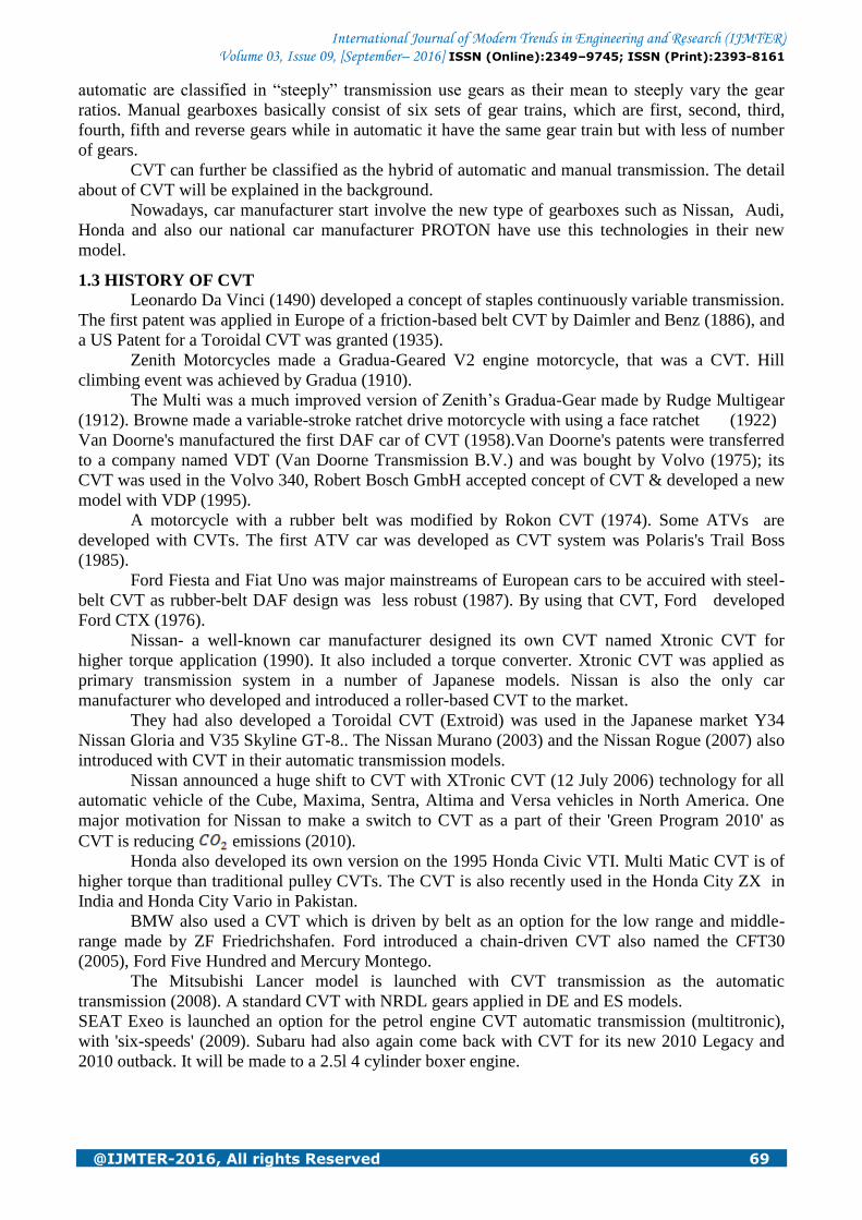
1.4.1 Variable-diameter pulley (VDP) or Reeves drive In the most of CVT system, there are two V-belt pulleys that are splined with driving and
driven shafts and moves perpendicular to their axes of rotation with V-belt running between them.
The speed ratio is varied by splitting the two sheaves which of one pulley near to each other and the
two sheaves of the other pulley apart from each other. The belt is moving at higher or lower position
of pulleys due to the v shape of the belt. The changes in the effective diameters of the pulleys change
the overall speed ratio. The centre distance between the driver and driven pulleys does not change,
and neither the length of the belt. Thus continuous variation in the speed ratio done by means of both
pulleys‟ adjustment in diameter (one larger in diameter, the other smaller in diameter)
simultaneously maintains the proper amount of tension on the belt.
Fig.1.1 Variable-Diameter Pulley CVT
[1]
The efficiency of a CVT depends on stiffness of V-belt in the pulley's direction of axis
perpendicular to it in order to make only less radial changes while sliding in and out of the pulleys.
Each element of the chain has conical, which is accurately fits and slides to the pulley if running of
the belt is on the outer radius of the pulley. As the belt runs into the pulleys the contact area would be
small. The contact area depends upon the contact of the number of elements of chain, thus the chain
is made of lots of very small elements. The radial thickness of the pulley of the belt is changing
between maximum gear ratio and minimum gear ratio according to torque. That is why the axis
between the pulleys is kept as thin as possible. A lubricant film is applied to the sheaves of the
pulleys. It should be required thick in proportion so that so that the pulley and the belt don‟t touch
and must be thin in order not to lose power. Additionally, the chain elements stabilize by 12 steel
bands. And from this each band must be thin enough so that it bends easily. In the stack of bands
each band responds to a slightly different speed ratio, and so they always slide over each other so
lubrication oil is required between them. The centre bands are used as the chain linkages and the
outer bands slide to stabilize chain.
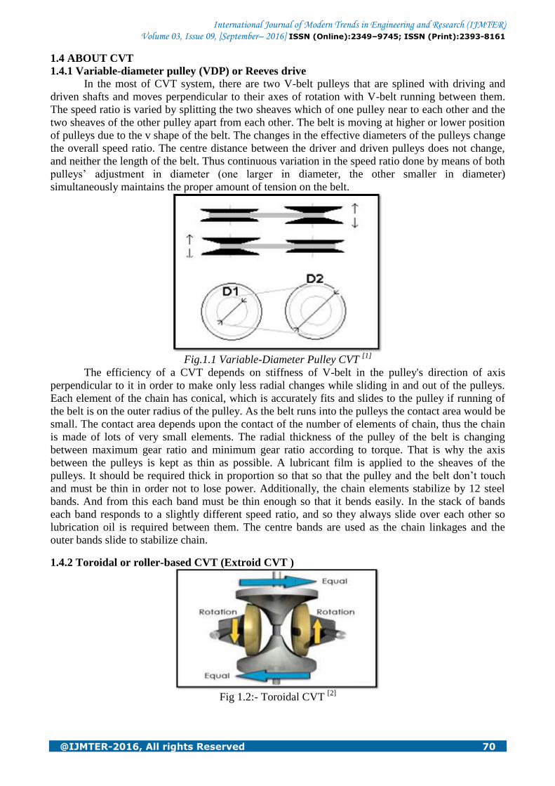
1.4.2 Toroidal or roller-based CVT (Extroid CVT )
Fig 1.2:- Toroidal CVT
[2]
International Journal of Modern Trends in Engineering and Research (IJMTER) Volume 03, Issue 09, [September– 2016] ISSN (Online):2349–9745; ISSN (Print):2393-8161
@IJMTER-2016, All rights Reserved 71
Toroidal CVTs are made of the torous which is combination of discs and rollers that transmit
power between the discs. The discs are same as two conical parts, with the sides dished so that the
two parts would fill up the centre of a torus. One disc would be input, and the other would be the
output. There are rollers that may vary the ratio and and transmit power from one torous to the other
torous. When the axis of the conical parts and the roller axis are perpendicular to each other, it makes
contact with the near-conical parts at exactly same diameter and gives a 1:1 i.e. direct gear ratio. The
roller can be rolled towards axis of the conical parts, by angle change as needed to maintain contact.
This makes the roller to contact the near-conical parts and gives a gear speed ratio of other than 1:1.
Systems may be partially or fully toroidal. Fully toroidal systems are efficient while partial toroidal
may require a torque converter, and hence less efficiency.
Some of toroidal CVTs are also continuously variable. And in toroidal CVT the direction of
the thrust force can be reversed.
1.4.3 Magnetic CVT or MCVT
The magnetic continuous variable transmission system was invented at the University of
Sheffield in 2006. MCVT takes an electrically controlled gear ratio (Variable magnetic
transmission). It is used as a power split device and matches an input speed from a prime-mover by
changing load and through a variation in path by means of electrical power. The MCVT is a more
efficient power-split device for hybrid vehicles, but also it has applications in an industrial drive
sectors as well as marine propulsion. The magnetic CVT can‟t transmit more torque than electric
motor of the same size, so it is not a better option for automobile transmission.
1.4.4 Ratcheting CVT
The ratcheting CVT is a one type of continuous variable transmission that is totally based on
static friction as the static friction is the major reason for transmission of power and is based on a set
of elements that engages successively and then disengages in between the driving and the driven
system, using oscillating motion with one-way clutches or ratchets that rectifies and sums only
"forward" movement. Varying linkage assembly within the oscillating elements adjust the
transmission gear ratio, so that the maximum linkage speed is changed, even when the mean linkage
speed would be constant. Power is transmitted from input to output only when the ratchet is engaged,
and hence when it is kept locked to a static friction mode where the driving & driven rotating
surfaces rotate together without slippage.
These CVTs can transfer the variable torque, because of their static friction actually increases
relatively as increase in torque, so slippage can be eliminated by designing the system properly.
Efficiency of this system is generally higher, because of the dynamic friction is come into chapter by
very slight transitional clutch speed changes. A major disadvantage of ratcheting CVTs is that causes
vibration by the transition in speed needed to accelerate the element.
Ratcheting CVTs are differed from VDPs and roller-based CVTs as they all are static
friction-based systems, and opposed to that was dynamic friction-based devices that lose significant
energy by slippage at twisting surfaces. The ratcheting CVT was used in one prototype of a bicycle
with the CVT transmission which is under U.S. Patent 5,516,132 in which strong pedalling torque
makes the mechanism to react against the spring, and changing the position of the ring gear/chain
wheel assembly to a concentric, lower gear position. When the pedalling relaxes to lower level, and
the transmission system adjusts to higher gears automatically, by increasing in transmission
vibration.
1.4.5 Hydrostatic CVT
Hydrostatic transmission system uses a variable displacement pump and also a hydraulic
motor. The power is transmitted by means of transmission of hydraulic fluid. The torque
transmission efficiency of this type is more, but it can be sensitive to contamination. Some designs
are more costlier. However, the advantage that they have, the hydraulic motor can be placed directly
on the wheel hub, and that allows suspension system more flexible and eliminates the losses the
friction in between differential components and the drive shaft. Hydrostatic transmission of CVT is
International Journal of Modern Trends in Engineering and Research (IJMTER) Volume 03, Issue 09, [September– 2016] ISSN (Online):2349–9745; ISSN (Print):2393-8161
@IJMTER-2016, All rights Reserved 72
easier to the application area because all forward as well as reverse speeds can be achieved using a
single lever.
Some heavy equipment also be used by a hydrostatic transmission; i.e. agricultural machinery
including foragers and some tractors. Heavy earth-moving equipment manufactured by Caterpillar.
Hydrostatic CVTs are generally not used for the applications where high torque is required because
heat t is produced by the feeding oil.
The Honda had launched the first on road vehicle DN-01 motorcycle is with hydrostatic drive
that causes a variable displacement of the axial piston pump by varying an angle of swash plate.
1.4.6 Cone CVT The cone known as evens friction cone, in the cone CVT, changes the effective gear or speed
ratio by means of one or more conical rollers. In the simplest cone CVT, the single-cone that uses a
wheel which moves through the slope of the cone, and vary the diameter between lower and wider
position of diameter.
The twin cone mesh system is also a more-sophisticated type of cone CVT.
In a cone CVT, the torque is transmitted via oscillating cones by friction from a variable
number of cones to a central and barrel-shaped hub. The convex surface of the hub with a radius of
curvature which is smaller than the radius of the cones. Each cone and hub makes contact at only one
point.
The Warko was introduced which is made of cone CVT in Berlin during the 6th International
CTI Symposium of Innovative Automotive Transmissions (2007).
A major advantage of the Warko is that is not using a clutch: the engine is giving power to
the wheels, and the rear drive is carried by using an epicyclic system in output.
1.4.7 Radial Roller CVT The working principle of Radial roller CVT is same as an oil compression engines, common
steel rollers are compressed in place of compressing oil.
The traction fluid transmits the motion between rollers and rotors, so that the proper friction
between the surfaces and slows down wearing is ensured. The tangential speed variation is not
showed by radial rollers. So mechanical efficiency and reliability increases.
1.4.8 Planetary CVT
In a planetary CVT, The adjustment of gear ratio depends upon tilting the axes of spheres in a
continuous manner, to provide different contact radius, which turns drive input and output discs. The
system has multiple "planets" to transfer torque through multiple fluid patches. One commercial
implementation of this type is the NuVinci Continuously Variable Transmission.
1.5 WORKING OF CVT
In the traditional transmission system the gears are used that provides a given number of
speed ratios (or speeds). The transmission changes gears to have the most appropriate ratio for a
given speed i.e. Lowest gears for starting, middle gears for acceleration, and higher gears for fuel-
efficient cruising.
Although there are different types of CVT, uses a pair of variable-diameter pulley sheaves,
each is shaped like a pair of opposing sheaves, with a metal belt, rubber belt or chain running
between them. One pulley is connected to the engine (input shaft), the other to the drive wheels
(output shaft).
The sheaves split on the axis perpendicular to the rotation of the pulleys and changes the
diameter of the pulleys. The variation in pulleys diameter is due to centrifugal force. Different
infinitely gear ratios can be achieved by changing the diameter of the both pulleys (driving and
driven) simultaneously.
In the starting of the vehicle the low speed gear ratios can be achieved. Then to accelerate the
vehicle, infinitely speed ratio can be achieved. And for higher speed the condition of overdrive also
be achieved.

International Journal of Modern Trends in Engineering and Research (IJMTER) Volume 03, Issue 09, [September– 2016] ISSN (Online):2349–9745; ISSN (Print):2393-8161
@IJMTER-2016, All rights Reserved 73
1.6 INFORMATION ABOUT VEHICLE
SUZUKI MAX 100
Suzuki max 100 was widely used in India. It gave more competition to the other bikes of the
same feature like Hero-Honda CD 100, Kawasaki, Bajaj CT 100 etc.
Body
Light weight, easy to handle.
Kick start
Telescopic oil damped suspension.(front)
Swinging Arm Hydraulic Shock Absorber with coaxial spring (rear)
Minimum ground clearance – 156 mm
Overall length – 1895 mm.
Control
Kick start.
98.2 cc engine deliver maximum output of 5.74 KW @ 5500 rpm.
12-volt 2.5 Ah/10 hr Battery.
4 speed constant mesh transmission.
Rear suspension with swinging arm hydraulic shock absorbers.
Front & rear drum brakes.
12.0 L fuel tank.
Small size vehicle.
Low price of vehicle.
Mileage and Economy
Average of above 60 km/l.
Fuel tank capacity - 12.0 Litters.
Almost 100 cc engine.
Fig 1.3 Vehicle selected for Study (Suzuki Max 100)
II. LITERATURE REVIEW
Bunches of literature is present on power train analysis and on various types of Continuously
Variable Transmissions (CVT) use in small size vehicles.. The work reviewed in this chapter would
deal with power train analysis for small size vehicle, performance of continuous variable
transmission system in vehicle, result data analysis of CVT used in vehicles & ways of operating
CVT system in vehicle.
2.1 DESIGN AND FABRICATION OF CONTINUOUS VARIABLE TRANSMISSION IN
FOUR WHEELER [5]
M. Anand Partheeban
SUMMARY:-The transmission is being very easy. A CVT system changes the driven pulley
diameter (i.e. Distance between two conical pulleys) with respect to speed and hence it changes
infinite gear ratio. Here in this paper, the driving pulley is kept constant. Only the driven pulley
changes the dimension accordingly speed. The simulation of the vehicle acceleration performance is
International Journal of Modern Trends in Engineering and Research (IJMTER) Volume 03, Issue 09, [September– 2016] ISSN (Online):2349–9745; ISSN (Print):2393-8161
@IJMTER-2016, All rights Reserved 74
carried out and that gives result that both drivability and fuel economy for the vehicle with CVT are
better than the one with manual transmission or multi ratio automatic transmission. CVTs use
infinitely gear ratios instead of gears to attain optimal speed. CVT is the better option for
transmission system in modern automobile vehicles.
Here in the paper Mr. Anand partheeban concludes the data for four wheeler vehicle. And it
gives better results then manual transmission.
2.2 FUEL OPTIMAL CONTROL OF CVT POWER TRAINS [6]
R. Pfiffner, L. Guzzella, C.H. Onder
SUMMARY:-Here in this paper the authors described that CVT changes gear ratio infinitely, this
change of speed ratio can be carried accordingly speed. CVT gives a better efficiency because it
changes the speed ratio according to quasi static curve i.e the best efficiency of the curve. Here in the
paper numerical optimum control is carried out.
The optimal control problem was solved by numerical optimization package DIRCOL by
descritizing continuous time interval. The optimal solution consists by bringing the system to the
engine‟s best efficiency curve. So that fuel economy improvements of approximately 2.5% to 5%
can be achieved, depending on the classical approach used.
2.3 OPTIMIZATION AND EVALUATION OF A BELT DRIVEN CVT FOR 125 CC, 4
STROKE SCOOTER [7]
Vivek adyanathaye, N.B. Joshi, A.D Samant
SUMMARY:- Here in this paper the authours carried out the optimization and evaluation of a belt
driven CVT. The belt driven CVT gives optimum efficiency, if the losses due to belt transmission is
less. The optimization and evaluation of rubber „V‟ belt CVT used with a 125CC, 4 stroke scooter.
The programmable controlled pulleys are designed and commissioned on Test Rig. Parameter such
as fuel economy and acceleration is compared. They found that major loss of CVT occurs largely
due to belt. The belt which is stiffer in bending be more efficient.
Evaluation of the CVT system is carried out using test rig. They found that a CVT system is a
good for two wheeler.
2.4 AN EXPERIMENTALLY-VALIDATED MODEL OF RUBBER BELT CVT
MECHANICS [8]
G. Julio, J.S. Plant
SUMMARY:- Rubber-belt CVTs are implemented in many vehicles to get comfort. Their better
control mechanism makes the engine to run at constant RPM, at any driving conditions. This
behaviour is not accepted, considering today‟s comfort and pollution standards. So, better control
system is required to vary the transmission ratio in real time. They have developed a new technology,
a dynamic model of rubber-belt CVT system is developed by them to predict the axial force to be
applied by the system.
Rubber-belt CVT is working accordingly Newton‟s law of motion on a discretized belt.
Simulation results are carried out. It shows that it is good fit with experiments for both steady-state
condition and dynamic conditions.
We can improve the control ability of the driven pulley axial forces by using a device similar
to the drive pulley rather than torque-cam mechanism is useful to validate the model. The discrete
model developed in this paper would be improved to predict rubber-belt CVT mechanism under
clutching conditions.
2.5 PERFORMANCE OPTIMIZATION OF CVT FOR TWO-WHEELED VEHICLES [9]
C.H.ZHENG, W.S LIM and S.W CHA
SUMMARY- Here in this paper the first objective of the authors was to improve the efficiency of
the CVT. Dynamic model was carried out for CVT using the dynamic equations. A simulation
program was applied in Matlab/Simulink to analyse the performance of CVT. From the simulation, it
International Journal of Modern Trends in Engineering and Research (IJMTER) Volume 03, Issue 09, [September– 2016] ISSN (Online):2349–9745; ISSN (Print):2393-8161
@IJMTER-2016, All rights Reserved 75
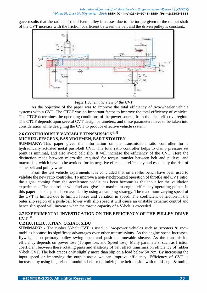
gave results that the radius of the driven pulley increases due to the torque given to the output shaft
of the CVT increase with the friction coefficient between the belt and the driven pulley is constant..
Fig.2.1 Schematic view of the CVT
As the objective of the paper was to improve the total efficiency of two-wheeler vehicle
systems with a CVT. The CTCF was an important factor to improve the total efficiency of vehicles.
The CTCF determines the operating conditions of the power source, from the ideal effective region.
The CTCF depends upon several CVT design parameters, and these parameters have to be taken into
consideration while designing the CVT to produce effective vehicle system.
2.6 CONTINUOUSLY VARIABLE TRNSMISSION [10]
MICHIEL PESGENS, BAS VROEMEN, BART STOUTEN
SUMMARY:-This paper gives the information on the transmission ratio controller for a
hydraulically actuated metal push-belt CVT. The total ratio controller helps to clamp pressure set
point is minimal, and also avoid belt slip. It will increase the efficiency of the CVT. Here the
distinction made between micro-slip, required for torque transfer between belt and pulleys, and
macro-slip, which have to be avoided for its negative effects on efficiency and especially the risk of
some belt and pulley wear.
From the test vehicle experiments it is concluded that on a roller bench have been used to
validate the new ratio controller. To improve a non-synchronized operation of throttle and CVT ratio,
the signal coming from the accelerator paddle has been become as the input for the validation
experiments. The controller will find and give the maximum engine efficiency operating points. In
this paper belt sleep has been avoided by using a clamping strategy. The maximum varying speed of
the CVT is limited due to limited forces and variation in speed. The coefficient of friction in the
outer slip region of a push-belt lower with slip speed it will cause an unstable dynamic control and
hence slip speed will increase when the torque capacity of a V-belt is exceeded.
2.7 EXPERIMENTAL INVESTIGATION ON THE EFFICIENCY OF THE PULLEY-DRIVE
CVT [11]
C.ZHU, H.LIU, J.TIAN, Q.XIAO, X.DU SUMMARY: - The rubber V-belt CVT is used in low-power vehicles such as scooters & snow
mobiles because its significant advantages over other transmissions. As the engine speed increases,
flyweights on primary pulley swing open and push the movable sheave. As the transmission
efficiency depends on power loss (Torque loss and Speed loss). Many parameters, such as friction
coefficient between these rotating parts and elasticity of belt affect transmission efficiency of rubber
V-belt CVT. The belt creeps only slightly more than slip on a load below 50 Nm. By increasing the
input speed or improving the output toque we can improve efficiency. Efficiency of CVT is
increased by using high elastic modulus belt or optimizing the belt tension with multi-angle& tuning

International Journal of Modern Trends in Engineering and Research (IJMTER) Volume 03, Issue 09, [September– 2016] ISSN (Online):2349–9745; ISSN (Print):2393-8161
@IJMTER-2016, All rights Reserved 76
on secondary pulley. By improving the development of high strength belt & design of driving and
driven pulleys, rubber belt CVT will finally be applicable for wider automotive application.
Fig.2.2 The experimental setup-v belt CVT
Fig.2.3 Efficiency comparison of the CVT with different torque
Graph shows the efficiency of CVT transmission system is incress with incress wirh speed of
engine. Because, at high speed the performance of CVT is improve. Graph shows the efficiency of
CVT transmission system is reduced with incress with speed ratio of engine. Because, at low speed
ratio the performance of CVT is improve.
III. DESIGN OF CVT
3.1 Determination of the "highest ratio"
Usually the "highest ratio" is selected so it allows achieving the maximum speed. The
advantage of higher ratio is it gives better fuel economy at highway. (But it would not get the top
speed.)
3.1.1. Available power
Considering that the maximum engine power of the bike is = 7.8 BHP,
The transmission efficiency (incl. rolling resistance),
International Journal of Modern Trends in Engineering and Research (IJMTER) Volume 03, Issue 09, [September– 2016] ISSN (Online):2349–9745; ISSN (Print):2393-8161
@IJMTER-2016, All rights Reserved 77
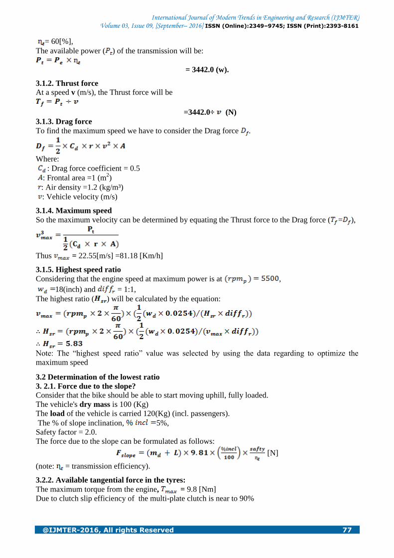
= 60[%],
The available power ( ) of the transmission will be:
= 3442.0 (w).
3.1.2. Thrust force
At a speed v (m/s), the Thrust force will be
=3442.0÷ (N)
3.1.3. Drag force
To find the maximum speed we have to consider the Drag force .
Where:
: Drag force coefficient = 0.5
: Frontal area =1 (m2)
: Air density =1.2 (kg/m³)
: Vehicle velocity (m/s)
3.1.4. Maximum speed
So the maximum velocity can be determined by equating the Thrust force to the Drag force ( = ),
Thus = 22.55[m/s] =81.18 [Km/h]
3.1.5. Highest speed ratio
Considering that the engine speed at maximum power is at ,
18(inch) and = 1:1,
The highest ratio ( ) will be calculated by the equation:
Note: The “highest speed ratio” value was selected by using the data regarding to optimize the
maximum speed
3.2 Determination of the lowest ratio
3. 2.1. Force due to the slope?
Consider that the bike should be able to start moving uphill, fully loaded.
The vehicle's dry mass is 100 (Kg)
The load of the vehicle is carried 120(Kg) (incl. passengers).
The % of slope inclination, 5%,
Safety factor = 2.0.
The force due to the slope can be formulated as follows:
[N]
(note: = transmission efficiency).
3.2.2. Available tangential force in the tyres:
The maximum torque from the engine, = 9.8 [Nm]
Due to clutch slip efficiency of the multi-plate clutch is near to 90%

International Journal of Modern Trends in Engineering and Research (IJMTER) Volume 03, Issue 09, [September– 2016] ISSN (Online):2349–9745; ISSN (Print):2393-8161
@IJMTER-2016, All rights Reserved 78
Clutch Efficiency,
So the tangential force in the tyres will be:
3.2.3. Lowest speed ratio
Equating and calculating lowest speed ratio results:
Now we get the required “lowest speed ratio” and “highest speed ratio”.
3.3 Addition of an external fixed ratio to obtain symmetric ratios: We get the results from the calculations are:
Low speed ratio,
High speed ratio,
Symmetric extreme ratios to be found:
= 0.91 is a correction factor.
Therefore, we have to add (in series) a final (fixed) reduction with a ratio of :
=9.94438
Now we have to find the new CVT's high and low speed ratios. These gives result by dividing initial
low speed ratio and high speed ratio by .
&
Conclusion: So we get the CVT's symmetric ratios will be &
3.4 Pulley diameter calculation
Considering that the smaller diameter of the pulley ( ) is 50 [mm] and that the bigger is ( ) will be
so that
The pulley groove angle: ß = 20˚
Fig 3.1 :- CAD Design of VDP (High Speed Ratio)
International Journal of Modern Trends in Engineering and Research (IJMTER) Volume 03, Issue 09, [September– 2016] ISSN (Online):2349–9745; ISSN (Print):2393-8161
@IJMTER-2016, All rights Reserved 79
IV. EXPERIMENTAL SET UP
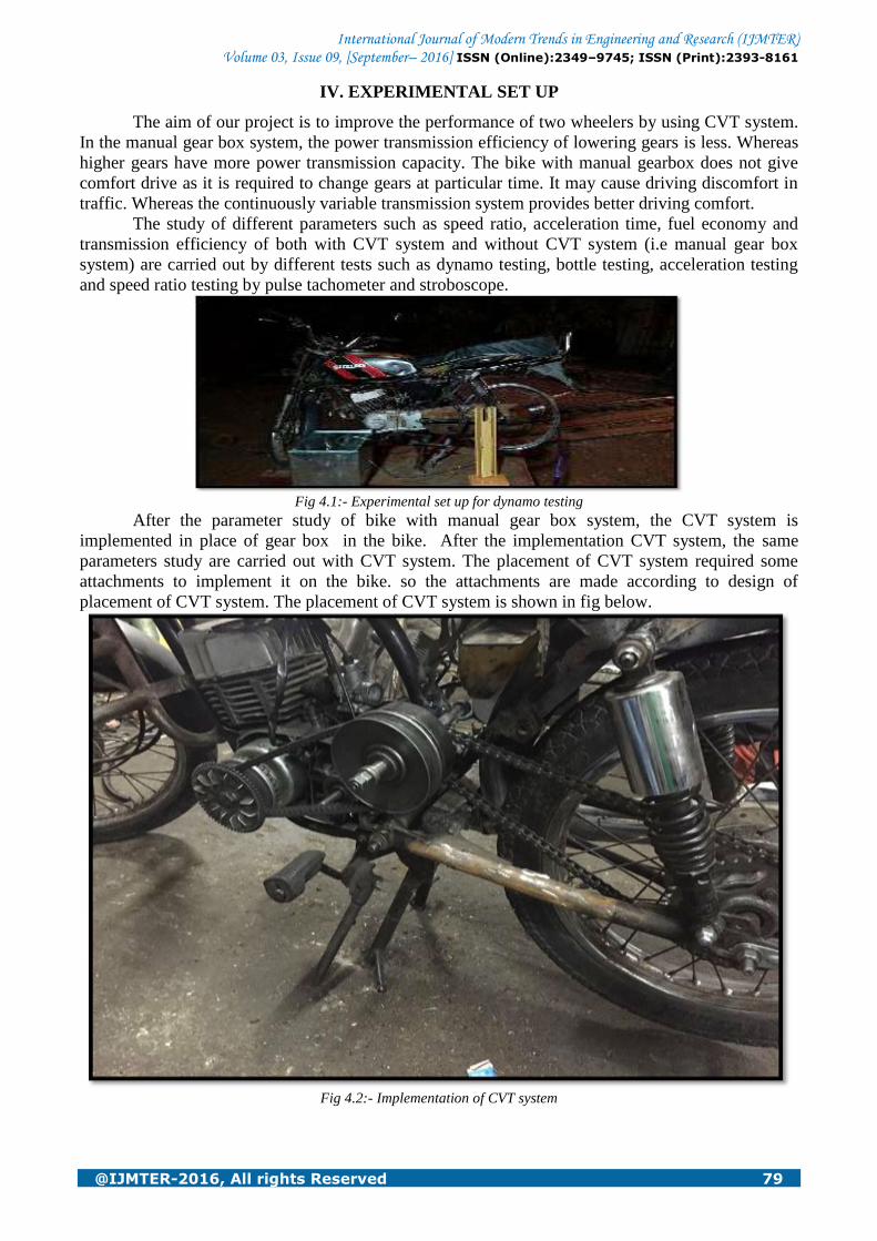
The aim of our project is to improve the performance of two wheelers by using CVT system.
In the manual gear box system, the power transmission efficiency of lowering gears is less. Whereas
higher gears have more power transmission capacity. The bike with manual gearbox does not give
comfort drive as it is required to change gears at particular time. It may cause driving discomfort in
traffic. Whereas the continuously variable transmission system provides better driving comfort.
The study of different parameters such as speed ratio, acceleration time, fuel economy and
transmission efficiency of both with CVT system and without CVT system (i.e manual gear box
system) are carried out by different tests such as dynamo testing, bottle testing, acceleration testing
and speed ratio testing by pulse tachometer and stroboscope.
Fig 4.1:- Experimental set up for dynamo testing
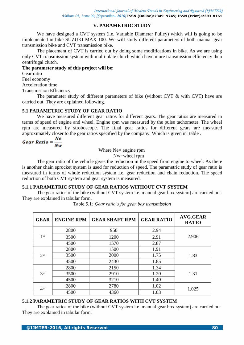
After the parameter study of bike with manual gear box system, the CVT system is
implemented in place of gear box in the bike. After the implementation CVT system, the same
parameters study are carried out with CVT system. The placement of CVT system required some
attachments to implement it on the bike. so the attachments are made according to design of
placement of CVT system. The placement of CVT system is shown in fig below.
Fig 4.2:- Implementation of CVT system
International Journal of Modern Trends in Engineering and Research (IJMTER) Volume 03, Issue 09, [September– 2016] ISSN (Online):2349–9745; ISSN (Print):2393-8161
@IJMTER-2016, All rights Reserved 80
V. PARAMETRIC STUDY
We have designed a CVT system (i.e. Variable Diameter Pulley) which will is going to be
implemented in bike SUZUKI MAX 100. We will study different parameters of both manual gear
transmission bike and CVT transmission bike.
The placement of CVT is carried out by doing some modifications in bike. As we are using
only CVT transmission system with multi plate clutch which have more transmission efficiency then
centrifugal clutch.
The parameter study of this project will be:
Gear ratio
Fuel economy
Acceleration time
Transmission Efficiency
The parameter study of different parameters of bike (without CVT & with CVT) have are
carried out. They are explained following.
5.1 PARAMETRIC STUDY OF GEAR RATIO We have measured different gear ratios for different gears. The gear ratios are measured in
terms of speed of engine and wheel. Engine rpm was measured by the pulse tachometer. The wheel
rpm are measured by stroboscope. The final gear ratios for different gears are measured
approximately closer to the gear ratios specified by the company. Which is given in table .
Where Ne= engine rpm
Nw=wheel rpm
The gear ratio of the vehicle gives the reduction in the speed from engine to wheel. As there
is another chain sprocket system is used for reduction of speed. The parametric study of gear ratio is
measured in terms of whole reduction system i.e. gear reduction and chain reduction. The speed
reduction of both CVT system and gear system is measured.
5.1.1 PARAMETRIC STUDY OF GEAR RATIOS WITHOUT CVT SYSTEM
The gear ratios of the bike (without CVT system i.e. manual gear box system) are carried out.
They are explained in tabular form.
Table.5.1: Gear ratio’s for gear box transmission
GEAR ENGINE RPM GEAR SHAFT RPM GEAR RATIO AVG.GEAR
RATIO
1ST
2800 950 2.94
2.906 3500 1200 2.91
4500 1570 2.87
2ND
2800 1500 1.91
1.83 3500 2000 1.75
4500 2430 1.85
3RD
2800 2150 1.34
1.31 3500 2910 1.20
4500 3210 1.40
4TH 2800 2780 1.02
1.025 4500 4360 1.03
5.1.2 PARAMETRIC STUDY OF GEAR RATIOS WITH CVT SYSTEM
The gear ratios of the bike (without CVT system i.e. manual gear box system) are carried out.
They are explained in tabular form.
International Journal of Modern Trends in Engineering and Research (IJMTER) Volume 03, Issue 09, [September– 2016] ISSN (Online):2349–9745; ISSN (Print):2393-8161
@IJMTER-2016, All rights Reserved 81
Table.5.2: Gear ratio’s for CVT system
Driving pulley RPM Driven pulley RPM Gear Ratio
2800 1040 2.40
3000 1120 2.32
3200 1560 2.05
3400 1890 1.79
3600 2660 1.35
3800 3170 1.19
4000 3960 1.01
4200 4330 0.96
4500 4730 0.95
5.2 PARAMETRIC STUDY OF FUEL ECONOMY
Automobiles have become a necessity in recent times. Without automobile vehicle,
transportation cannot be imagined. If we see the today‟s market it may be too much costly. So in
today‟s market, everyone consider the vehicle‟s fuel economy as important parameter while buying
the vehicle. So it is necessary to take the fuel consumption as an important study parameter to be
study.
Here fuel economy is measured practically by bottle test. We have measured fuel
consumption on highway which is suitable condition to measure bike‟s fuel economy.
5.2.1 PARAMETRIC STUDY OF FUEL ECONOMY WITHOUT CVT SYSTEM The tabulated data regarding the bottle test for the fuel economy of the bike with manual gear
box system is given below.
Table.5.3: Fuel consumption reading (without CVT)
FUEL CONSUMPTIONS (mL) KILOMETERS
100 4.0
100 3.8
100 3.7
5.3 PARAMETRIC STUDY OF ACCELERATION TIME
In today‟s world the youth generation wants sudden acceleration in their vehicle. So
acceleration is another important parameter to be studied. The parametric study of acceleration time
is carried out by measuring the different speed at different time. The time for acceleration is
measured by stop watch.
5.3.1 PARAMETRIC STUDY OF ACCELERATION TIME WITHOUT CVT
The acceleration time for the different speeds in different gears is measured. The tabulated
data regarding the acceleration time is shown below.
Table.5.4 Parametric study of acceleration time (without CVT)
GEAR INITIAL
VELOCITY
FINAL
VELOCITY
Time
(t1))
Time
(t2)
Time
(t3)3)
Avg time
(t)
1ST 0 20 9.10 8.26 8.43 8.606
0 40 -- -- -- --
2ND 0 20 5.20 4.50 4.20 4.63
0 40 22.15 22.20 19.30 21.21
3RD 0 20 5.08 5.01 5.84 5.31
0 40 13.04 13.73 14.08 13.62

International Journal of Modern Trends in Engineering and Research (IJMTER) Volume 03, Issue 09, [September– 2016] ISSN (Online):2349–9745; ISSN (Print):2393-8161
@IJMTER-2016, All rights Reserved 82
4TH 0 20 5.76 5.66 6.03 5.82
0 40 14.71 15.98 15.07 15.25
5.3.2 PARAMETRIC STUDY OF ACCELERATION TIME WITH CVT
The acceleration time for CVT system is measured. The data regarding the acceleration time
for the CVT system is given in tabular form.
Table.5.5: Parametric study of acceleration time with CVT
INITIAL
VELOCITY
FINAL
VELOCITY (
TIME
(s)
AVG (TIME
(T)T1E
0 20 12
12 0 20 13
0 20 11
0 20 13
0 40 19
20 0 40 18
0 40 21
0 40 20
5.4 PARAMETRIC STUDY OF TRANSMISSION EFFECIENCY
The transmission efficiency is an important parameter to study as the transmission efficiency
increases then automatically fuel economy improves and vehicle performance improves. So
transmission efficiency is the major aspect to be studied in terms of mechanical study of different
parameters‟.
The transmission efficiency can be defined as,” the ratio of brake power to the indicated power”.
Where = Brake Power = Indicated Power
The parametric study of transmission efficiency is carried out by using dynamo testing of the
bike. For studying the transmission efficiency by the dynamo testing, different equipment are
required. They are U-tube manometer, pulse tachometer, tachometer or stroboscope, weights for
different load conditions etc.
The u-tube manometer is used for measuring the pressure of air which is used to calculate the
indicated power of the vehicle. Whereas engine speed is measured by pulse tachometer. Pulse
tachometer measures the vibration pulses generated at spark plug and gives the engine speed. Engine
speed is also used for calculating indicated power
Indicated power is known as input power of dynamo and it can be calculated by following
formula.
=
Engine rpm is measured by the pulse tachometer. But in case of measurement of wheel rpm,
tachometer or stroboscope is used. The weight is placed so that wheel rim becomes a dynamo. The
weight of 5 kg and 10 kg are used to give different loads. Weights are used to calculate the torque.
Which is further used to calculate the brake power.
Brake power is known as the output power of the dynamo and it can be calculated by
following formula
Brake Power=

International Journal of Modern Trends in Engineering and Research (IJMTER) Volume 03, Issue 09, [September– 2016] ISSN (Online):2349–9745; ISSN (Print):2393-8161
@IJMTER-2016, All rights Reserved 83
5.4.1 PARAMETRIC STUDY OF TRANSMISSION EFFECIENCY WITHOUT CVT
The parametric study of transmission efficiency of the vehicle without CVT system is given
below in tabulated form
Table.5.6: Dynamo testing (without CVT)
GEAR Ne
(rpm)
Nw
(rpm)
LOAD
(Kg)
TORQUE
(Nm)
I.P
(watt)
B.P
(watt) ɳ
1ST
3350 800 5 11.45 2680 959.2 35.79
2700 385 10 22.91 2592 901.75 34.78
2ND
2980 1000 5 11.45 2384 1199.04 50.02
2520 500 10 22.91 2419.2 1167.74 48.26
3RD
2730 1330 5 11.45 2184 1594.72 73.01
2400 704 10 22.91 2304 1647.12 71.48
4TH
2600 1500 5 11.45 2080 1801.04 86.58
2200 765 10 22.91 2112 1788.23 84.66
5.4.2 PARAMETRIC STUDY OF TRANSMISSION EFFECIENCY WITH CVT
The parametric study of transmission efficiency of the vehicle without CVT system is given
below in tabulated form.
Table.5.7: Dynamo testing (with CVT)
Ne
(rpm)
Nw
(rpm)
LOAD
(Kg)
TORQUE
(Nm)
I.P
(watt)
B.P
(watt) ɳ
2637 550 5 11.45 2116.23 659.47 31.16
2863 930 5 11.45 2297.74 1115.32 48.54
3150 1470 5 11.45 2526.54 1762.59 69.76
3680 1980 5 11.45 2953.43 2374.10 80.39
3150 658 10 22.91 2528.18 1578.62 62.44
3370 846 10 22.91 2704.65 2029.66 75.04
3780 1015 10 22.91 3033.72 2436.91 80.32
4200 1230 10 22.91 3370.83 2950.92 87.54
5.5 COMPARATIVE ANALYSIS
The aim of our project is to improve the performance of two wheeler by using the CVT
system, for that different parameters such as speed ratios, acceleration time, fuel economy and
transmission efficiency are carried out.
To get a proper result, both the transmission system of the vehicle that is gear box and CVT
system are implemented on the same vehicle and analysis of different parameters are carried out for
both the system.
As the name suggests the CVT system continuously changes the speed ratios with the speed.
Where as in the gear box system it is required to changes the speed ratios or gear ratios. The CVT
system sets gear ratio automatically and gives comfort drive. CVT system gives the continuously
changing speed ratios from 0.95 to 2.4 where as with gear system it gives the practical gear ratios
from 0.99 to 2.909. Which gives that the CVT system transmits lower starting torque compare to
gear box system. where as after the actuating some speed, the CVT system gives better speed
compare to gear box system.
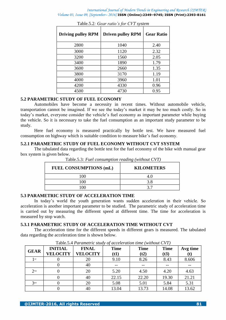
If we compare the acceleration time for both the system, it is having less time to carry the
vehicle to the speed of 20 to 40 km/h in the CVT system then the gear box system. As the CVT
system takes much time to get the speed of 20 km/hr due to its lower torque transmission system.
Comparative Analysis of Gear Ratios
International Journal of Modern Trends in Engineering and Research (IJMTER) Volume 03, Issue 09, [September– 2016] ISSN (Online):2349–9745; ISSN (Print):2393-8161
@IJMTER-2016, All rights Reserved 84
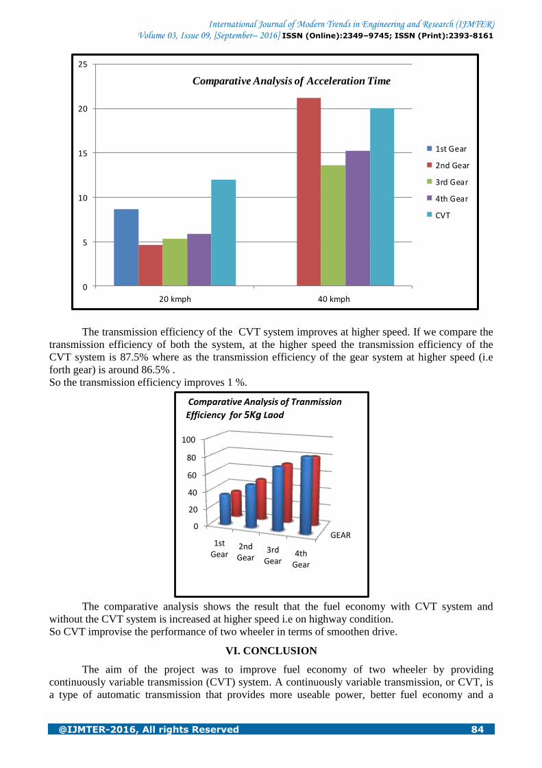
The transmission efficiency of the CVT system improves at higher speed. If we compare the
transmission efficiency of both the system, at the higher speed the transmission efficiency of the
CVT system is 87.5% where as the transmission efficiency of the gear system at higher speed (i.e
forth gear) is around 86.5% .
So the transmission efficiency improves 1 %.
GEAR0
20
40
60
80
100
1st Gear
2nd Gear
3rd Gear
4th Gear
Comparative Analysis of Tranmission
Efficiency for 5Kg Laod
The comparative analysis shows the result that the fuel economy with CVT system and
without the CVT system is increased at higher speed i.e on highway condition.
So CVT improvise the performance of two wheeler in terms of smoothen drive.
VI. CONCLUSION
The aim of the project was to improve fuel economy of two wheeler by providing
continuously variable transmission (CVT) system. A continuously variable transmission, or CVT, is
a type of automatic transmission that provides more useable power, better fuel economy and a
0
5
10
15
20
25
20 kmph 40 kmph
1st Gear
2nd Gear
3rd Gear
4th Gear
CVT
Comparative Analysis of Acceleration Time
International Journal of Modern Trends in Engineering and Research (IJMTER) Volume 03, Issue 09, [September– 2016] ISSN (Online):2349–9745; ISSN (Print):2393-8161
@IJMTER-2016, All rights Reserved 85
smoother driving experience than a traditional manual transmission. CVT, that is lighter in weight
and more efficient will be used, which has large and variable transmission ratio. CVT gives
different-different speed outputs at same acceleration level. The transmission efficiency and fuel
economy improves 1% and 5% respectively by using the CVT system. It provides a better speed
ratios and smoother drive compare to the manual gearbox transmission system.
VII. FUTURE SCOPE
We have designed a CVT system (i.e. Variable Diameter Pulley) . And we have implemented
the CVT system in the motorcycle with two stroke engine. As the two stroke engine has more power
loss then two stroke engine. Still in the two stroke engine it gives better performance but in the four
stroke engine it improves the performance. The compactness in the placement of the CVT system is
required. It would be necessary to have modifications in the frame of the vehicle in order to
accommodate the CVT system in place of conventional gearbox system.
Based on our theoretical study, it is our prediction that the following mentioned parameters
can be improved more with 4 stroke engine.
Acceleration Time to carry different speeds
Acceleration Distance
Fuel Economy
Efficiency
REFERENCES
[1] M. Anand Partheeban, Design and fabrication of continuous variable transmission of four wheeler, International
Journal of Advanced Engineering Technology, E-ISSN 0976-3945
[2] R. Pfiffner, L. Guzzella, C.H. Onder, 2002, Fuel optimal control of cvt power trains, Control Engineering Practice
11 (2003) 329–336
[3] Vivek adyanathaye, N.B. Joshi, A.D Samant , 1994, Optimization and evaluation of a belt driven cvt for 125 cc, 4
stroke scooter
[4] G. Julio, J.S. Plant , 2011, An experimentally-validated model of rubber-belt CVT mechanics, Mechanism and
Machine Theory 46 (2011)1037–1053
[5] C.H.ZHENG, W.S LIM And S.W CHA ,2011, Performance optimization of CVT for Two wheeler, International
Journal of Automotive Technology, Vol. 12, No. 3, pp. 461−468
[6] Michiel Pesgens, Bas Vroemen, Bart Stouten, May 2006, Control of a hydraulically actuated continuously variable
transmission, Drivetrain Innovations b.v., Horsten 1, 5612 AX, The Netherlands, Vol. 44, No. 5,
[7] C.Zhu, H.Liu, J.Tian, Q.Xiao, X.Du, 2010, Experimental investigation on the efficiency of the pulley-drive CVT,
International Journal of Automotive Technology, Vol. 11, No. 2, pp. 257−261
[8] URL: global.yamaha-motor.com/yamahastyle/technology/spread/003/img/img03_l.gif
[9] URL : http://s.hswstatic.com/gif/cvt-17.gif
[10] URL: http://www.varibox.com/sites/default/files/iCVT10.jpg
[11] URL: http://s.hswstatic.com/gif/cvt-18.jpg Author1, Author2, "Paper Title", Journal Name with Issue number, Page
Number, Year of Publish
Related Documents