EasyChair Preprint № 5457 A Review of Wire Arc Additive Manufacturing (WAAM) of Aluminium Composite, Process, Classification, Advantages, Challenges, and Application Noor Hmoud Athaib, Ali Hubi Haleem and Basem Al-Zubaidy EasyChair preprints are intended for rapid dissemination of research results and are integrated with the rest of EasyChair. May 4, 2021

Welcome message from author
This document is posted to help you gain knowledge. Please leave a comment to let me know what you think about it! Share it to your friends and learn new things together.
Transcript

EasyChair Preprint№ 5457
A Review of Wire Arc Additive Manufacturing(WAAM) of Aluminium Composite, Process,Classification, Advantages, Challenges, andApplication
Noor Hmoud Athaib, Ali Hubi Haleem and Basem Al-Zubaidy
EasyChair preprints are intended for rapiddissemination of research results and areintegrated with the rest of EasyChair.
May 4, 2021
A review of Wire Arc Additive Manufacturing (WAAM) of
Aluminium Composite, Process, Classification, Advantages,
Challenges, and Application
Noor Hmoud Athaib1, Ali Hubi Haleem1 and Basem Al-Zubaidy1
1Department of Metallurgical Engineering, College of Materials Engineering,
University of Babylon, Babylon, Iraq
Abstract. Wire-arc additive manufacturing (WAAM) is a common metal 3D printing
technique that offers several benefits, including the high rate of deposition, cheap price, and
efficacy for complex parts. Even though (WAAM) has demonstrated its ability to meet the
demands of manufacture components on medium-to-large size made of (Al) for the automotive
and other related industries, WAAM cannot currently use as a complete production procedure
due to practical issues such as mechanical properties that aren't matched and the presence of
significant residual stresses. the AM technologies offer promising new benefits with the MMCs
as a solution for some challenges. This article reviews the MMCs Mixing technique and their
critical issues, AM classification, WAAM process with advantages and challenges. also
reviews WAAM of some AMCs with different reinforcements and power sources. The results
of the study of the influence of reinforcement particles on the structure showed that they were
changed grains structure from the columnar dendrite to equiaxial dendrites after the
solidification and improves hardness.
1. Introduction
With the advancement of technology in various high-tech fields, the need for high-performance
materials is becoming increasingly urgent. Metal matrix composites (MMC) have been people's
favourite artefacts in many areas, like aerospace and military, and they are often irreplaceable. Most
MMCs' mechanical properties are determined by their reinforcing fillers. Nitride ceramics (TiN, BN)
[1, 2], oxide ceramics (Al2O3, SiO2) [3, 4], carbides (TiC, WC) [5, 6], and various carbon allotropes
[7] are the most recent MMC reinforcement materials. The inclusion of raw materials in the
manufacturing process, which includes various assembly and rapid prototyping processes, is referred
to as additive manufacturing (AM) [8]. The American Society for Testing and Materials (ASTM) and
the International Organization for Standardization (ISO) characterized AM as "the process of
connecting materials to make objects from 3D model data, typically layer by layer" [9]. AM have gain
its importance not only due to the many advantages it has such the ability to handle multiple
materials (metals, polymers, ceramics, and other materials), but also its ability to produce novel,
complex, and close to the final shape of the part with no additional tools and requirement for re-fixing.
AM ensures single-piece assembly or custom manufacturing [10]. Because the process has a
centralized manufacturing process, it reduces task time and material waste, thereby improving overall

procurement costs, thus improving the buy-to-flight rate (BTF), and together with enhancing the
feedback flexibility of turning raw materials into structures [11].
Aluminium and aluminium alloys, among the massive metal materials, are very common in many
emerging industries (such as transportation and aerospace) due to their lightweight. At the same time,
metal three-dimensional (3D) printing technology [12,13] is the key driving force behind Industry 4.0.
In this regard, it is critical to investigate the majority of the effects of metal 3D printing on the
production of aluminium MCs. [14].
2. Metal Matrix Composites (MMCs)
A metal matrix and a dispersed metal, ceramic, or polymer process are usually used in MMCs [15]. In-
situ and ex-situ MMCs are the two types [16]. Figure )1a ( shows the ex-situ MMC process, which
involves fabricating reinforcement materials (generally particles) and mixing them into a metal matrix
externally. In an MMC like this, the reinforcement is regularly broken and cold-welded as particles.
As shown in Figure )1b), in-situ MMCs are made by a chemical reaction between halide salts and
metal substrates and are thermodynamically more stable than ex-situ MMCs. In-situ, MMC has a
compatible, high interface bonding power, as well as better mechanical properties. MMC has many
benefits, but the production of completely dense MMC is hindered by potential challenges (such as gas
entrapment, particle aggregation, and macro-and micro-cracks) [17].
Figure 1. Graphical illustration of MMC (a) ex-situ (b) in-situ [16]
2.1 Mixing Techniques of MMCs.
available a variety of MMC mixing techniques. The main goal of these processing methods is to
achieve uniform reinforcement material dispersion in the matrix to achieve defect-free
microstructures. Table 1 shows a variety of MMC mixing techniques [17].
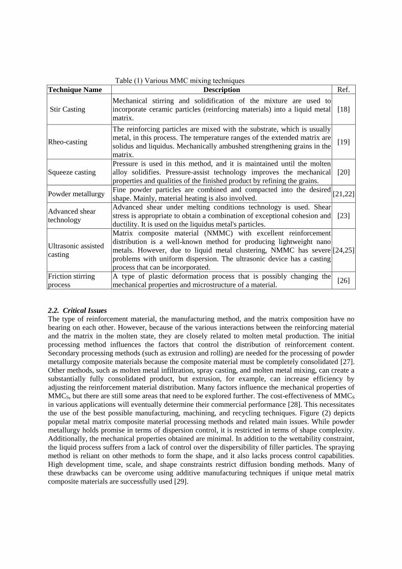
Table (1) Various MMC mixing techniques
Technique Name Description Ref.
Stir Casting
Mechanical stirring and solidification of the mixture are used to
incorporate ceramic particles (reinforcing materials) into a liquid metal
matrix.
[18]
Rheo-casting
The reinforcing particles are mixed with the substrate, which is usually
metal, in this process. The temperature ranges of the extended matrix are
solidus and liquidus. Mechanically ambushed strengthening grains in the
matrix.
[19]
Squeeze casting
Pressure is used in this method, and it is maintained until the molten
alloy solidifies. Pressure-assist technology improves the mechanical
properties and qualities of the finished product by refining the grains.
[20]
Powder metallurgy Fine powder particles are combined and compacted into the desired
shape. Mainly, material heating is also involved. [21,22]
Advanced shear
technology
Advanced shear under melting conditions technology is used. Shear
stress is appropriate to obtain a combination of exceptional cohesion and
ductility. It is used on the liquidus metal's particles.
[23]
Ultrasonic assisted
casting
Matrix composite material (NMMC) with excellent reinforcement
distribution is a well-known method for producing lightweight nano
metals. However, due to liquid metal clustering, NMMC has severe
problems with uniform dispersion. The ultrasonic device has a casting
process that can be incorporated.
[24,25]
Friction stirring
process
A type of plastic deformation process that is possibly changing the
mechanical properties and microstructure of a material. [26]
2.2. Critical Issues The type of reinforcement material, the manufacturing method, and the matrix composition have no
bearing on each other. However, because of the various interactions between the reinforcing material
and the matrix in the molten state, they are closely related to molten metal production. The initial
processing method influences the factors that control the distribution of reinforcement content.
Secondary processing methods (such as extrusion and rolling) are needed for the processing of powder
metallurgy composite materials because the composite material must be completely consolidated [27].
Other methods, such as molten metal infiltration, spray casting, and molten metal mixing, can create a
substantially fully consolidated product, but extrusion, for example, can increase efficiency by
adjusting the reinforcement material distribution. Many factors influence the mechanical properties of
MMCS, but there are still some areas that need to be explored further. The cost-effectiveness of MMCS
in various applications will eventually determine their commercial performance [28]. This necessitates
the use of the best possible manufacturing, machining, and recycling techniques. Figure (2) depicts
popular metal matrix composite material processing methods and related main issues. While powder
metallurgy holds promise in terms of dispersion control, it is restricted in terms of shape complexity.
Additionally, the mechanical properties obtained are minimal. In addition to the wettability constraint,
the liquid process suffers from a lack of control over the dispersibility of filler particles. The spraying
method is reliant on other methods to form the shape, and it also lacks process control capabilities.
High development time, scale, and shape constraints restrict diffusion bonding methods. Many of
these drawbacks can be overcome using additive manufacturing techniques if unique metal matrix
composite materials are successfully used [29].

Figure 2. The key issues of the traditional MMC processing route [29]
3. Additive Manufacturing
Additive manufacturing is a technique that originated from 3D printing and enables the
manufacture of end-use parts directly from CAD data. The use of complex intermediate tools is
eliminated due to the layering of materials [30]. This would significantly reduce the manufacturing
cycle and allow for greater design freedom and the development of more complex shapes. AM also
allows for environmentally friendly product design. Other advantages of additive manufacturing
include waste reduction, environmental safety, and optimum design for lean manufacturing. [31]. The
American Society for Testing and Materials (ASTM) describes AM and divides AM technology into
seven divisions, according to ASTM International Committee F42. Only four of these methods can
make metal parts, and only one of them can be combined with the addition of metal fillers to make
additively produced moulded parts, as shown in Figure (3) [11].
Figure 3. AM process classification with corresponding material handling functions [11]

3.1. WAAM Process
Since 1920, the technology of depositing weld metal to manufacture entire components has been
adopted, and this technology is now used as an arc and additive manufacturing (WAAM) technology.
This technology has several benefits, including a higher BTF ratio as compared to conventional
manufacturing methods, the ability to potentially ignore the size limit of component manufacturing,
and cost-effectiveness in comparison to powder-based processes that depend on expensive materials
[11]. WAAM is included in to direct energy deposition (DED), according to ASTM F2792-12a [32].
It's also known as a heat source made from an electric arc and a raw material made from metal wire.
Figure (4) depicts this mechanism schematically. WAAM is based on the automatic welding process
as a concept. Rapid prototyping (RP), shape melting (SM), shape welding (SW), shape Metal
deposition (SMD), solid freeform fabrication (SFF), and even 3D welding have all been used to
describe WAAM in recent years. [33].
3.1.1 Classification of WAAM
According to the nature of the heat source, there are usually three types of WAAM technology, as
shown in Figure (2):
1. GMAW-based (Gas Metal Arc Welding) [35].
2. GTAW-based (Gas Tungsten Arc Welding) [36].
3. PAW-based (Plasma Arc Welding) [37].
GMAW-based WAAM deposition rates are 2-3 times higher than GTAW or PAW-based techniques.
GMAW-based WAAM, on the other hand, is less stable, and more spatter and welding fumes are
generated because the current is applied directly to the raw material. The processing conditions and
productivity of the target component are directly affected by the choice of WAAM technology [38].
Figure 4. A schematic diagram of (WAAM) process [34].

Figure 5. Typical classification of WAAM [11]
3.1.2. WAAM Advantages and Challenges
*Cost-efficient
Because of the significant difference in raw material costs, wire-based technology is 2 to 50 times
more cost-effective than powder-based technology. WAAM will save 7–69% on titanium component
production compared to traditional methods [39].
*BTF ratio
When manufacturing complex aero-engine parts from inventory, a BTF ratio of 30 is not unusual.
When using WAAM to make the same pieces, on the other hand, a significant amount of material can
be saved. The BTF ratio for high-cost titanium alloys is 1.2 [40].
*High deposition rate
WAAM can achieve a steel deposition rate of close to 10 kg h-1 [40,41], which is about 16 times
faster than the powder deposition process's maximum rate of 600 h-1 [42]. The explanation for this is
that the shape of a single bead will vary drastically. The powder-based process produces beads with a
thickness varying from a few microns to 1 mm [43], while the WAAM process produces beads with a
height of 1-2 mm [44,45], which may increase in proportion to the deposition rate.
*Solidification behaviours
The large weld pool solidification in WAAM can be compared to the traditional casting method,
though the latter's solidification behaviour in the centre and periphery will differ [11].
*High production rate
To achieve high productivity, the wire feed speed should be optimized, as this allows for uncontrolled
weld deposition, raising the process's instability and, as a result, the surface roughness. (Williams et
al.) believe that [40], To keep the BTF ratio below 1.5, the deposition rate for steel must be less than 4
kg h-1 and less than 1 kg h-1 for aluminium and titanium alloys. The conclusion is that the deposition-
prepared WAAM object must be machined. The rate is higher than the above. As a result, WAAM is
not the final forming operation for any component where surface roughness is a critical factor [11].
*Thermal cycles effect
The solidified weld metal and the substrate are subjected to thermal cycling as metal is added layer by
layer using an electric arc. The exothermic effect induces partial melting and heat treatment of the
previously deposited layer, as well as extending the non-isothermal heat treatment effect or three to
four layers below the deposited weld bead. The amount of change is determined by the amount of heat

applied and the material's thermophysical properties. Thermal cycling causes the deposited metal to
expand and contract, causing a significant amount of residual stress in the base material and formed
components [46,47].
*Production of medium- to large-scale
Unlike laser and electronic-based methods, which restrict the total size of objects due to the size of the
chamber, WAAM may create objects of any size. WAAM is therefore ideal for the production of
medium and large parts due to its high deposition rate and potentially limitless metal deposition
capability. However, the greater bead volume and higher surface roughness limit its application to the
development of low- and medium-complex parts as compared to the powder-based method (25 μm or
less cited by Gu [42]) [11].
*The mechanical properties
WAAM products' mechanical strength falls short of that of forged products with identical chemical
properties or filler wires. WAAM sections have highly directional tensile properties that are
determined by the deposition pattern used during the object's creation. WAAM pieces are stronger in a
particular direction due to their tensile properties [11].
4. Aluminium Alloys Aluminium alloys welding has always been difficult due to the aluminium oxide layer's formation and
solidification nature. WAAM use in aluminium alloys is limited due to the main issue of porosity. Due
to this restriction, some research into the effects of heat treatment on WAAM Al parts has been
conducted. Heat treatment is not possible for all aluminium alloys. When it occurs During the
manufacturing of aluminium parts, it is preferable to use alternating current (AC) [48]. Removal of a
higher melting point natural surface oxide film (aluminium oxide). If this is not the case, the molten
residue will become trapped inside the molten pool, contributing to holes and internal defects as well
as a major reduction in the mechanical properties of the component. Periodic polarity reversals cause
turbulent pool dynamics, which causes the extremely difficult WAAM of aluminium alloy, which can
result in reduced component accuracy. Fundamental properties of aluminium alloy welding include
high thermal expansion coefficient, high solidification shrinkage, high thermal conductivity, a broad
solidification temperature range, and high hydrogen solubility [49].
5. Review of WAAM of Aluminium Matrix Composites
Deng Yaqi et al investigated TiB2 reinforced Al-7Si-Cu-Mg composites made by arc addition
and casting. The mechanical properties of aluminium-based composites are improved by TiB2
particles, which are nano- or sub-micron in size and have normal and circular morphology. In terms of
microstructure and properties of aluminium matrix composites, two related processes are compared.
The distribution of alloying elements in the TiB2-reinforced Al-Si-based composite material of
(WAAM) is found to be more distributed by comparing SEM and EDS study. TiB2 particles have a
smaller size and a more uniform distribution. The hardness of the deposited microstructure increases
when compared to the as-cast condition. The silicon phase in the as-cast sample is very large and is
constantly distributed around the grain boundary, while the silicon phase in the deposited
microstructure is dispersed and smaller. The heat treatment of WAAM Al-Si composite material was
carried out, and two heat treatment mechanisms were compared: solution post ageing and ageing.
After one ageing, the hardness of the material rises to 127 HV10, and under the condition of ageing
after solid solution, it increases to 139 HV10. It is found that the reinforced Al-Si-based composite
material can reach the supersaturated solution state through WAAM [ 50].
Yang Qingfeng et al studied (TiB2+Al-Si) composites made by TIG WAAM. The microstructure and
mechanical properties were investigated. Large-volume samples were prepared using TIG wire and
electric arc AM technology. In-situ TiB2+Al-Si composite material was used as the deposition metal,
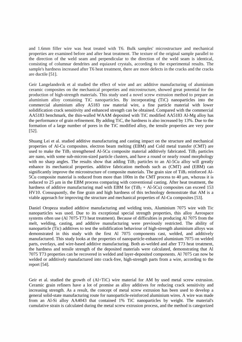
and 1.6mm filler wire was heat treated with T6. Bulk samples' microstructure and mechanical
properties are examined before and after heat treatment. The texture of the original sample parallel to
the direction of the weld seam and perpendicular to the direction of the weld seam is identical,
consisting of columnar dendrites and equiaxed crystals, according to the experimental results. The
sample's hardness increased after T6 heat treatment, there are more defects in the cracks and the cracks
are ductile [51].
Geir Langelandsvik et al studied the effect of wire and arc additive manufacturing of aluminium
ceramic composites on the mechanical properties and microstructure, showed great potential for the
production of high-strength materials. This study used a novel screw extrusion method to prepare an
aluminium alloy containing TiC nanoparticles. By incorporating (TiC) nanoparticles into the
commercial aluminium alloy A5183 raw material wire, a fine particle material with lower
solidification crack sensitivity and enhanced strength can be obtained. Compared with the commercial
AA5183 benchmark, the thin-walled WAAM deposited with TiC modified AA5183 Al-Mg alloy has
the performance of grain refinement. By adding TiC, the hardness is also increased by 13%. Due to the
formation of a large number of pores in the TiC modified alloy, the tensile properties are very poor
[52].
Shuang Lei et al. studied additive manufacturing and casting impact on the structure and mechanical
properties of Al-Cu composites. electron beam melting (EBM) and Cold metal transfer (CMT) are
used to make the TiB2 strengthened Al-5Cu composite material additively fabricated. TiB2 particles
are nano, with some sub-micron-sized particle clusters, and have a round or nearly round morphology
with no sharp angles. The results show that adding TiB2 particles to an Al-5Cu alloy will greatly
enhance its mechanical properties. additive fabrication methods such as (CMT) and (EBM) can
significantly improve the microstructure of composite materials. The grain size of TiB2 reinforced Al-
5Cu composite material is reduced from more than 100m in the CMT process to 40 μm, whereas it is
reduced to 25 μm in the EBM process comparing with conventional casting. After heat treatment, the
hardness of additive manufacturing mad with EBM for (TiB2 + Al-5Cu) composites can exceed 153
HV10. Consequently, the fine grain and high hardness of this technology demonstrate that AM is a
viable approach for improving the structure and mechanical properties of Al-Cu composites [53].
Daniel Oropeza studied additive manufacturing and welding tests, Aluminium 7075 wire with Tic
nanoparticles was used. Due to its exceptional special strength properties, this alloy Aerospace
systems often use (Al 7075-T73 heat treatment). Because of difficulties in producing Al 7075 from the
melt, welding, casting, and additive manufacturing were previously restricted. The ability of
nanoparticle (Tic) additives to test the solidification behaviour of high-strength aluminium alloys was
demonstrated in this study with the first Al 7075 components cast, welded, and additively
manufactured. This study looks at the properties of nanoparticle-enhanced aluminium 7075 on welded
parts, overlays, and wire-based additive manufacturing. Both as-welded and after T73 heat treatment,
the hardness and tensile strength of the deposited materials were calculated, demonstrating that Al
7075 T73 properties can be recovered in welded and layer-deposited components. Al 7075 can now be
welded or additively manufactured into crack-free, high-strength parts from a wire, according to the
report [54].
Geir et al. studied the growth of )Al+TiC( wire material for AM by used metal screw extrusion.
Ceramic grain refiners have a lot of promise as alloy additives for reducing crack sensitivity and
increasing strength. As a result, the concept of metal screw extrusion has been used to develop a
general solid-state manufacturing route for nanoparticle-reinforced aluminium wires. A wire was made
from an Al-Si alloy AA4043 that contained 1% TiC nanoparticles by weight. The material's
cumulative strain is calculated during the metal screw extrusion process, and the method is categorized

as a severe plastic deformation (SPD) method. It has been discovered that after the metal screw has
been extruded, The grain refinement effect can be limited by a chemical reaction between silicon and
TiC particles. Arc bead deposition on the board was done with metal screw extrusion and commercial
materials. After arc deposition, the addition of TiC causes the crystal grain form to change from
cylindrical to equiaxed, increasing the hardness. The AA4043-TiC material had a large number of
pores, which may have been caused by hydrogen contamination on the TiC surface before metal screw
extrusion. The results are promising and point in a new direction for the advancement of aluminium
alloy additive manufacturing [55].
Peng et al. investigated the impact of integrating TiCnps into WAAM on mechanical
properties, grain boundary structural evolution, solute redistribution, crystal orientation
evolution, and phase transformation (AA 2319). The addition of 5 m TiCps to the system
decreased the nucleation free energy, allowing nuclei to form on the particle's surface. It was
discovered that the addition of (TiCnps) eliminates grain boundary segregation and columnar
crystal defects. The addition of approximately 80 nm TiCnps decreased the solid-liquid
growth rate (R), indicating that TiCnps were more likely to be spread successfully as
nucleation particles inside the grains. Micro-pools with several nucleation sites impaired grain
boundary segregation and increased the concentration of copper in the Al matrix. Due to the
difference in Cu atom concentration, the fine spot-like θ'-CuAl2 phase, as well as the
dendritic θ -CuAl2 phase along the grain boundary, were all transformed into semi-coherent
alpha-Al+ θ CuAl2 phases. Due to the strong interfacial bonding between the fine spot-like
phase and TiCnps and the Al matrix, the deposited 3219 aluminum alloy exhibited improved
mechanical properties. Table (2a) Summary of Literature Review study the effect of aluminium-based composite additive
manufacturing on microstructure and mechanical properties
Reference [50] [51] [52] [53] [54] [55] [56,57]
Alu
min
um
-ba
sed
co
mp
osi
te
Matrix Al–7Si–Cu–
Mg
Al-7Si-
1Mg-Cu AA5183 Al-5Cu AA7075 AA4043 AA2319
Reinforced TiB2 TiB2 TiC TiB2 TiC TiC TiC
Volume or mass
fraction ----------- 2.5 wt% 1 vol% TiC -------- ---- 1 wt.%
(0.5,1.0,
1.5,2.0)
wt.%
particles size
Nano or
submicron-
sized
------- 40–60 nm
Nano and some
submicron
clusters
Nano 40–60
nm 40 nm
Morphology or
crystal structure
regular with
round -------
fcc crystal
structure
round and near-
round (no sharp
angles)
____
____ fcc
Power source CMT TIG CMT (CMT) ,(EBM) TIG GMAW MIG
Welding wire diameter
(mm) 2.5 1.6 1.2 2.0 3.2 1.1–1.2
The dimension of the
as-deposited
sample(mm)
140*20*80 -------- 220*8*80 180 *200*80 ------
------
------
Current (A) 170 ------ 85 170, 35 mA 180 100 101
Voltage (V) 19.2 ------ 16.6 18.3, 60 ----- 19
Feeding speed 5.8 m/min ------- 5.0 m/min 3.8m/min
500 mm/min
254
mm/min 9 mm/s 2m/min

Table (2d) Summary of literature review study of the effect of aluminium-based composite additive
manufacturing on microstructure and mechanical properties (The composite fabrication method and
the result)
The composite fabrication
method The Result
Ya
qi
et
al,
20
18
[5
0]
The composite material is
manufactured by using a
mixture salts method.
In comparison to as-cast and as-deposited welding wire, the
alloy elements in as-deposited samples are often in solid
solubility, and the second phase is dispersed.
The welding wire had the highest hardness due to its internal
tension. The deposited state has a higher hardness than the as-
cast state. The increase in hardness can be due to a decrease in
grain size and an increase in solid solubility.
In the as-cast sample, the silicon phase is wide and uniformly
distributed along the grain boundary, while the silicon phase
in the deposited microstructure is dispersed and smaller.
Qin
gfe
ng
et
al,2
019
[51]
prepared using a mixture of
salts method
The parallel to the weld structure is identical to the
perpendicular to the weld structure. Columnar and equiaxed
crystals make the sedimentary sample's composition, with
silicon and TiB2 particles distributed along the grain
boundary.
TiB2 particles aggregate in a variety of ways, resulting in grain
and Si refinement.
The grain size of the sample increases significantly after T6
heat treatment, and the shape of silicon varies from the
original strip to a lump with a size of 2-5 um.
After T6, the sedimentary sample's hardness increases.
Gei
r et
al,
2020
[52]
In the screw extrusion
process, the TiC modified
wire is made by mixing
monolithic AA5183 wire with
TiC nano-powder.
The deposited WAAM thin wall has compared with the
commercial AA5183 benchmark, the (TiC-+AA5183) alloy
shows refined grains, the hardness is also increased by 13%.
The tensile properties of the TiC modified alloy is weak due to
the formation of a large number of pores.
Sh
ua
ng
et
al,
20
20
[53
]
Prepare Al composite material
by salt-metal reaction method.
WAAM (TiB2+ Al-5Cu) will refine the microstructure of
composite materials and reduce grain size (more than 100 μm)
than the traditional casting using CMT and EBM technology.
AM technology becomes a promising method for optimizing
microstructure and mechanical properties
The performance of composite materials.

Dan
iel
et a
l,2
02
0 [
54]
-------------
Can weld common spaceship 7075 T73 aluminium the Al
7075 welding wire reinforced with TiC nanoparticles can
restore mechanical properties through T73 heat treatment after
welding.
Al 7075 T73 is manufactured by a wire-based additive
manufacturing process, and its performance is similar to that
of wrought materials.
Quantify the preliminary mechanical properties of Al
7075+TiCnps during welding and after T73 heat treatment.
Gei
r et
al,
202
0 [
55
]
A wire of AA4043 is cut into
25±10 mm granules, then
cleaned and heat to ensure
that any organic residues are
removed. The granules are
mixed with 1% by weight of
TiC powder in a cylindrical
plastic container. The (AL +
TiC) mixture was rolled and
mixed in the air at 70 rpm for
five days. There is a black dry
TiC coating on the particles.
A ternary Intermetallic phase form from a solid-state chemical
reaction occurs between (Al +Si + TiC).
The arc deposition of TiC reinforced wire shows that after the
solidified columnar dendrites are transformed into equiaxed
dendrites, the grain structure has changed and the hardness has
increased. In the accumulated deposit material, there were a
lot of hydrogen pores, which may be attributed to TiC
pollution in the air.
Pen
g e
t al
,2020 [
56]
The coating speed is used to
control the coated TiCnps with
different mass fractions.
By incorporating TiCnps into the WAAM process, uneven
microstructural features and columnar crystals were removed,
the average grain size was reduced, and grain boundary
segregation and increased Cu element concentration in Al-
matrix were inhibited.
When TiCnps is applied, the solid-liquid interface's growth rate
slows down.
Because of the lower solidification rate, secondary dendrites
will expand, promoting the transformation of dendrites to
equiaxed dendrites.
When subjected to tensile stress, the samples without TiCnps
cracks begin at the grain boundary in the brittle CuAl2 phase,
propagating along the grain boundary. On the brittle alpha-
Al+-CuAl2 step, cracks begin to form within the grain in
TiCnps samples. To improve strength and plasticity, cracks
must bypass the TiCnps and '-phase.
6. Applications of WAAM
As a result of its diversified uses, WAAM has wide industrial applications,
including aerospace and maritime transportation. Concerning the complexity of the more
of the work and the alloy is, the more prominent WAAM will be. Figure (6) depicts the
fabrication and thermal testing of liquid rocket engine equipment used at NASA's
Marshall Space Flight Center [58]. WAAM made a 2.1-meter-long mechanical excavator
that weighs just over a ton, as shown in Figure (7) [60].
The results of this are conventional industrial and artistic, as well as 3D printing allows
for versatile and effective work and gives architectural and esthetic designers freedom to
apply the use of WAAM. Mass art is sure to emerge because of the popularization of

metal sculpture[58]. The example in Figure (8), of the full-metallic bridge from MX3D
and Arup engineers at Imperial College that was constructed and tested in Amsterdam's
harbor, is provided as an example of WAAM flexibility and versatility [61].
Figure 6:WAAM Liquid rocket engine combustion device [59]
Figure 7: WAAM forming large mechanical arm. a Printed arm. b Installed arm [60]
Figure 8: a Load testing of the MX3D bridge; b the MX3D bridge at Dutch Design Week 2018 [61]
7.Conclusions
This article reviewed the manufacture of aluminium metal matrix composites through additive manufacturing
(WAAM). Taking into account the key aspects of metal matrix material processing, the WAAM process, the
advantages and challenges of this method, it was found that the additive manufacturing method is considered to
be a better alternative method for processing metal matrix composite materials. The mixing methods of MMCs
and their critical issues, classification of AM processes, WAAM process with advantages and challenges also
were reviewed. The review was also included the discussion of WAAM of some AMCs with different
reinforcement materials (TiC, TiB2) and different power sources. The results showed that the solidified deposited
material with reinforcing particle prepared by wire arc welding had an identical structure in both parallel and
perpendicular to the weld direction. Where the columnar dendrite grain’s structure changed to equiaxial
dendrites shape, leading to improves hardness and other mechanical properties. The deposited material had a
large number of pores, which may be attributed to contamination of the reinforcing particles exposed to the air.
References
[1] Ma, J., Kang, J., & Huang, T. (2016). Novel application of ultrasonic cavitation for fabrication
of TiN/Al composites. Journal of Alloys and Compounds, 661, 176-181.
[2] Hu, Z., & Tong, G. (2015, October). Laser sintered thin layer graphene and cubic boron nitride
reinforced nickel matrix nanocomposites. In AOPC 2015: Micro/Nano Optical
Manufacturing Technologies; and Laser Processing and Rapid Prototyping Techniques (Vol.
9673, p. 967302). International Society for Optics and Photonics.
[3] Rajkovic, V., Bozic, D., & Jovanovic, M. T. (2010). Effects of copper and Al2O3 particles on
characteristics of Cu–Al2O3 composites. Materials & Design, 31(4), 1962-1970.
[4] Wang, H., Geng, H., & Liu, C. (2012). The influence of SiO2 on the aluminum borate whisker
reinforced aluminum phosphate wave-transparent materials. Procedia Engineering, 27, 1222-
1227.
[5] Ma, Z. Y., Mishra, R. S., & Tjong, S. C. (2002). High-temperature creep behavior of TiC
particulate reinforced Ti–6Al–4V alloy composite. Acta materialia, 50(17), 4293-4302.
[6] Yuan, J., Zhang, X., Li, B., Wang, X., & Sun, K. (2017). Microstructure and tribological
behavior of NiAl/WC composites fabricated by thermal explosion reaction at 800° C. Journal
of Alloys and Compounds, 693, 70-75.
[7] Bakshi, S. R., Lahiri, D., & Agarwal, A. (2010). Carbon nanotube reinforced metal matrix
composites-a review. International materials reviews, 55(1), 41-64.
[8] WHITE L. ADDITIVE MANUFACTURING MATERIALS STANDARDS, TESTING AND
APPLICABILITY. Nova Science Publishers, New York; 2015.
[9] ISO/ASTM52900 - 15 Standard Terminology for Additive Manufacturing - General Principles -
Terminology, Standard, American Society for Testing Materials, West Conshohocken, USA,
2015.
[10] Gao, W., Zhang, Y., Ramanujan, D., Ramani, K., Chen, Y., Williams, C. B., ... & Zavattieri, P.
D. (2015). The status, challenges, and future of additive manufacturing in
engineering. Computer-Aided Design, 69, 65-89
[11] Derekar, K. S. (2018). A review of wire arc additive manufacturing and advances in wire arc
additive manufacturing of aluminium. Materials science and technology, 34(8), 895-916.
[12] Chen, M., Li, X., Ji, G., Wu, Y., Chen, Z., Baekelant, W., ... & Kruth, J. P. (2017). Novel
composite powders with uniform TiB2 nano-particle distribution for 3D printing. Applied
Sciences, 7(3), 250.
[13] Chen, T., & Lin, Y. C. (2017). Feasibility evaluation and optimization of a smart manufacturing
system based on 3D printing: a review. International Journal of Intelligent Systems, 32(4),
394-413.
[14] Hu, Z., Chen, F., Xu, J., Nian, Q., Lin, D., Chen, C., ... & Zhang, M. (2018). 3D printing
graphene-aluminum nanocomposites. Journal of Alloys and Compounds, 746, 269-276.
[15] Hu, Y., & Cong, W. (2018). A review on laser deposition-additive manufacturing of ceramics
and ceramic reinforced metal matrix composites. Ceramics International, 44(17), 20599-
20612.
[16] Gu, D. (2015). Laser additive manufacturing of high-performance materials. Springer.
[17] Mahmood, M. A., Popescu, A. C., & Mihailescu, I. N. (2020). Metal matrix composites
synthesized by laser-melting deposition: a review. Materials, 13(11), 2593.
[18] Gupta, M., Lai, M. O., & Lim, C. Y. H. (2006). Development of a novel hybrid aluminum-

based composite with enhanced properties. Journal of Materials Processing
Technology, 176(1-3), 191-199
[19] Naher, S., Brabazon, D., & Looney, L. (2005). Development and assessment of a new quick
quench stir caster design for the production of metal matrix composites. Journal of Materials
Processing Technology, 166(3), 430-439
[20] Narasimha, B. G., Krishna, V. M., & Xavior, A. M. (2013). A review on processing of
particulate metal matrix composites and its properties. International Journal of Applied
Engineering Research, 8(6), 647-666.
[21] Das, S., Behera, R., Datta, A., Majumdar, G., Oraon, B., & Sutradhar, G. (2010). Experimental
investigation on the effect of reinforcement particles on the forgeability and the mechanical
properties of aluminum metal matrix composites. Materials Sciences and
Applications, 1(05), 310.
[22] Manjunathal, H., & Dinesh, P. (2013). Fabrication and properties of dispersed carbon nanotube-
Al6061 composites. International Journal of Innovative Research in Science, Engineering
and Technology, 2(2), 500-507.
[23] Barekar, N., Tzamtzis, S., Dhindaw, B. K., Patel, J., Babu, N. H., & Fan, Z. (2009). Processing
of aluminum-graphite particulate metal matrix composites by advanced shear
technology. Journal of Materials Engineering and Performance, 18(9), 1230-1240.
[24] Barekar, N. S., Tzamtzis, S., Babu, N. H., Fan, Z., & Dhindaw, B. K. (2009). Processing of
ultrafine-size particulate metal matrix composites by advanced shear
technology. Metallurgical and Materials Transactions A, 40(3), 691.
[25] Donthamsetty, S. (2010). Investigation on mechanical properties of A356 nanocomposites
fabricated by ultrasonic assisted cavitation. Journal of Mechanical Engineering, 41(2), 121-
129.
[26] Chen, C. L., Tatlock, G. J., & Jones, A. R. (2010). Microstructural evolution in friction stir
welding of nanostructured ODS alloys. Journal of Alloys and Compounds, 504, S460-S466.
[27] Diehl, W., & Stöver, D. (1990). Injection moulding of superalloys and intermetallic
phases. Metal Powder Report, 45(5), 333-338.
[28] Mishra, R. S., Bieler, T. R., & Mukherjee, A. K. (1995). Superplasticity in powder metallurgy
aluminum alloys and composites. Acta metallurgica et materialia, 43(3), 877-891.
[29] Behera, M. P., Dougherty, T., & Singamneni, S. (2019). Conventional and additive
manufacturing with metal matrix composites: A perspective. Procedia Manufacturing, 30,
159-166.
[30] Gero, J. S., Maher, M. L., & Sudweeks, F. (Eds.). (1995). Computational models of creative
design: third International Round-Table Conference on Computational Models of Creative
Design, Heron Island, Queensland, Australia, 3-7 December 1995. Key Centre of Design
Computing at the University of Sydney.
[31] Wong, K. V., & Hernandez, A. (2012). A review of additive manufacturing, ISRN
Mech. Eng, 1, 1-10.
[32] Standard, A. S. T. M. (2012). Standard terminology for additive manufacturing
technologies. ASTM International F2792-12a.
[33] Ding, D., Pan, Z., Cuiuri, D., & Li, H. (2015). Wire-feed additive manufacturing of metal
components: technologies, developments and future interests. The International Journal of
Advanced Manufacturing Technology, 81(1), 465-481.
[34] McAndrew, A. R., Rosales, M. A., Colegrove, P. A., Hönnige, J. R., Ho, A., Fayolle, R., ... &
Pinter, Z. (2018). Interpass rolling of Ti-6Al-4V wire+ arc additively manufactured features
for microstructural refinement. Additive Manufacturing, 21, 340-349.
[35] Ding, D., Shen, C., Pan, Z., Cuiuri, D., Li, H., Larkin, N., & van Duin, S. (2016). Towards an
automated robotic arc-welding-based additive manufacturing system from CAD to finished
part. Computer-Aided Design, 73, 66-75.
[36] Dickens, P. M., Pridham, M. S., Cobb, R. C., Gibson, I., & Dixon, G. (1992). Rapid prototyping

using 3-D welding. In 1992 International Solid Freeform Fabrication Symposium.
[37] Spencer, J. D., Dickens, P. M., & Wykes, C. M. (1998). Rapid prototyping of metal parts by
three-dimensional welding. Proceedings of the Institution of Mechanical Engineers, Part B:
Journal of Engineering Manufacture, 212(3), 175-182.
[38] Wu, B., Pan, Z., Ding, D., Cuiuri, D., Li, H., Xu, J., & Norrish, J. (2018). A review of the wire
arc additive manufacturing of metals: properties, defects and quality improvement. Journal
of Manufacturing Processes, 35, 127-139.
[39] Williams, S., & Martina, F. (2015). Wire+ arc additive manufacturing vs. traditional machining
from solid: a cost comparison. Technical report. Welding engineering and laser processing
Centre, Cranfield University.
[40] Williams, S. W., Martina, F., Addison, A. C., Ding, J., Pardal, G., & Colegrove, P. (2016).
Wire+ arc additive manufacturing. Materials Science and Technology, 32(7), 641-647.
[41] Williams, S. W., Martina, F., Addison, A. C., Ding, J., Pardal, G., & Colegrove, P. (2016).
Wire+ arc additive manufacturing. Materials Science and Technology, 32(7), 641-647.
[42] Gu, D. (2015). Laser additive manufacturing (AM): classification, processing philosophy, and
metallurgical mechanisms. In Laser additive manufacturing of high-performance
materials (pp. 15-71). Springer, Berlin, Heidelberg.
[43] Herzog, D., Seyda, V., Wycisk, E., & Emmelmann, C. (2016). Additive manufacturing of
metals. Acta Materialia, 117, 371-392.
[44] Xiong, J., & Zhang, G. (2013). Online measurement of bead geometry in GMAW-based
additive manufacturing using passive vision. Measurement Science and Technology, 24(11),
115103.
[45] Geng, H., Li, J., Xiong, J., Lin, X., & Zhang, F. (2017). Optimization of wire feed for GTAW
based additive manufacturing. Journal of Materials Processing Technology, 243, 40-47.
[46] Withers, P. J., & Bhadeshia, H. K. D. H. (2001). Residual stress. Part 1–measurement
techniques. Materials science and Technology, 17(4), 355-365.
[47] Withers, P. J., & Bhadeshia, H. K. D. H. (2001). Residual stress. Part 2–Nature and
origins. Materials science and technology, 17(4), 366-375.
[48] Wang, H., Jiang, W., Ouyang, J., & Kovacevic, R. (2004). Rapid prototyping of 4043 Al-alloy
parts by VP-GTAW. Journal of Materials Processing Technology, 148(1), 93-102.
[49] Ding, Y., Muñiz-Lerma, J. A., Trask, M., Chou, S., Walker, A., & Brochu, M. (2016).
Microstructure and mechanical property considerations in additive manufacturing of
aluminum alloys. MRS Bulletin, 41(10), 745-751.
[50] Deng, Y., Li, X., Wu, L., Yang, Q., & Chen, Y. (2018, July). Microstructure and Performance
of WAAM TiB 2-Reinforced Al–Si-Based Composites. In Chinese Materials
Conference (pp. 321-328). Springer, Singapore.
[51] Yang, Q. F., Xia, C. J., & Deng, Y. Q. (2019). Microstructure and Mechanical Properties of
TiB2/Al-Si Composites Fabricated by TIG Wire and Arc Additive Manufacturing.
In Materials Science Forum (Vol. 944, pp. 64-72). Trans Tech Publications Ltd [52] Hu, Z., Chen, F., Xu, J., Nian, Q., Lin, D., Chen, C., ... & Zhang, M. (2018). 3D printing
graphene-aluminum nanocomposites. Journal of Alloys and Compounds, 746, 269-276.
[53] Lei, S., Deng, Y. Q., Li, X. F., Wu, L., & Chen, Y. C. (2020). Effect of Casting and Additive
Manufacturing on the Microstructure and Mechanical Property of Al-Cu Composites.
In Materials Science Forum (Vol. 993, pp. 718-722). Trans Tech Publications Ltd.
[54] Langelandsvik, G., Grandcolas, M., Skorpen, K. G., Furu, T., Akselsen, O. M., & Roven, H. J.
(2020). Development of Al-TiC Wire Feedstock for Additive Manufacturing by Metal Screw
Extrusion. Metals, 10(11), 1485.
[55] Langelandsvik, G., Grandcolas, M., Skorpen, K. G., Furu, T., Akselsen, O. M., & Roven, H. J.
(2020). Development of Al-TiC Wire Feedstock for Additive Manufacturing by Metal Screw
Extrusion. Metals, 10(11), 1485.
[56] Jin, P., Liu, Y., Li, F., Li, J., & Sun, Q. (2021). Realization of structural evolution in grain
boundary, solute redistribution and improved mechanical properties by adding TiCnps in
wire and arc additive manufacturing 2219 aluminium alloy. Journal of Materials Research
and Technology, 11, 834-848.
[57] Jin, P., Liu, Y., & Sun, Q. (2021). Evolution of crystallographic orientation, columnar to
equiaxed transformation and mechanical properties realized by adding TiCps in wire and arc
additive manufacturing 2219 aluminum alloy. Additive Manufacturing, 39, 101878
[58] Gradl, P. R., Greene, S. E., Protz, C., Bullard, B., Buzzell, J., Garcia, C., ... & Cooper, K. G.
(2018). Additive manufacturing of liquid rocket engine combustion devices: a summary of
process developments and hot-fire testing results. In 2018 Joint Propulsion Conference (p.
4625).
[59] Liu, J., Xu, Y., Ge, Y., Hou, Z., & Chen, S. (2020). Wire and arc additive manufacturing of
metal components: a review of recent research developments. The International Journal of
Advanced Manufacturing Technology, 1-50.
[60] Greer, C., Nycz, A., Noakes, M., Richardson, B., Post, B., Kurfess, T., & Love, L. (2019).
Introduction to the design rules for metal big area additive manufacturing. Additive
manufacturing, 27, 159-166.
[61] Buchanan, C., & Gardner, L. (2019). Metal 3D printing in construction: A review of methods,
research, applications, opportunities and challenges. Engineering Structures, 180, 332-348.
Related Documents