•

Welcome message from author
This document is posted to help you gain knowledge. Please leave a comment to let me know what you think about it! Share it to your friends and learn new things together.
Transcript
Loughborough UniversityInstitutional Repository
A review of analyticalmethods for aircraft
structures subjected tohigh-intensity random
acoustic loads
This item was submitted to Loughborough University's Institutional Repositoryby the/an author.
Citation: CUNNINGHAM, P.R. and WHITE, R.G., 2004. A review of analyt-ical methods for aircraft structures subjected to high-intensity random acousticloads. Proceedings of the Institution of Mechanical Engineers, Part G: Journalof Aerospace Engineering, 218(3), pp. 231-242.
Additional Information:
• This is an article from the journal, Proceedings of the Institution of Me-chanical Engineers, Part G: Journal of Aerospace Engineering [ c© IMechE]. It is also available at: http://dx.doi.org/10.1243/0954410041872898
Metadata Record: https://dspace.lboro.ac.uk/2134/4872
Version: Published
Publisher: Professional Engineering Publishing / c© IMECHE
Please cite the published version.

This item was submitted to Loughborough’s Institutional Repository (https://dspace.lboro.ac.uk/) by the author and is made available under the
following Creative Commons Licence conditions.
For the full text of this licence, please go to: http://creativecommons.org/licenses/by-nc-nd/2.5/
SPECIAL ISSUE PAPER
A review of analytical methods for aircraft structuressubjected to high-intensity random acoustic loads
P R Cunningham1* and R G White
2
1School of Engineering Sciences, University of Southampton, UK2Emeritus Professor of Vibration Studies, University of Southampton, UK
Abstract: A review of the acoustic fatigue design process for aircraft structures is presented in thispaper, together with the current design guides, which are used to predict the stresses that anacousticallly loaded aircraft structure may experience in service. These methods are based on lineartheory and use the single-degree-of-freedom approximation method. A recent programme of researchwhich uses this method together with the finite element method to predict the root mean squarestrains experienced by acoustically excited, doubly curved sandwich panels is briefly discussed. Recentdevelopments in prediction methods based on the non-linear dynamic response of thermoacousticloaded structures are reviewed, and suggestions are made as to possible future directions in the area ofacoustic fatigue research.
Keywords: acoustic fatigue, aircraft structures, analytical methods
NOTATION
c wavespeed (m/s)cv viscous damping coefficientdB decibelsE elastic modulus (N/m2)f frequency (Hz)Fn generalized forceG shear modulus (N/m2), pressure spectrumH frequency response functioni complex number
ffiffiffiffiffiffiffi�1p
j index valueJn joint acceptanceka acoustic wavenumber (1/m)m mass per unit areaRx radius of curvature in the x direction (m)Ry radius of curvature in the y direction (m)w, _ww, €ww out-of-plane displacement, velocity,
acceleration (m, m/s, m/s2)x,y,z Cartesian coordinates
o radian frequency (rad/s)f mode shaper density (kg/m3)m micro ð610�6Þ
n Poisson’s ratios direct stress (N/m2)c spatial distribution of pressurez viscous damping ratio
< real part of a complex number= imaginary part of a complex number
Acronyms
ASTOVL advanced short take-off and verticallanding
CAA computational aeroacousticsCFRP carbon-fibre reinforced plasticESDU Engineering Sciences Data UnitFE finite elementFEA finite element analysisOASPL overall sound pressure levelPWT progressive wave tuber.m.s. root mean squareSPL sound pressure level
1 INTRODUCTION
With the introduction of the gas turbine engine and theresulting rapid development of more powerful engines,there followed an increase in the number of reportedfatigue failures of aircraft skin structures close to the jet
The MS was received on 24 February 2003 and was accepted afterrevision for publication on 18 September 2003.* Corresponding author: School of Engineering Sciences—AerospaceEngineering, University of Southampton, Highfield, Southampton,Hampshire S017 1BJ, UK.
231
G00603 # IMechE 2004 Proc. Instn Mech. Engrs Vol. 218 Part G: J. Aerospace Engineering
exhaust [1]. This led to a range of investigations byseveral aircraft industries and research establishments inan attempt to both understand and alleviate thisproblem. The majority of these early investigationsinvolved experimental studies using both simple testpanels and actual aircraft structures, and excitation wasprovided by sirens, random noise generators and aircraftengines. This early work led to the development of thefirst design nomographs for acoustically excited aircraftstructures [2].
A response prediction method for acoustically excitedmetallic structures was first developed by Miles [3]. Inthat study, Miles considered an elastic structuresubjected to random loading and simplified the analysisby assuming the structure to have only a single degree offreedom. He also used the concept of cumulativedamage to analyse the fatigue behaviour of suchstructures. Miles derived an expression for the equiva-lent root mean square stress for a single degree offreedom system under random loading. Miner’s hypo-thesis of cumulative damage was then used to estimatethe fatigue life of the structure.
Powell [4] took this work one stage further byconsidering the normal mode approach. The modes ofvibration of the structure were assumed to beuncoupled; hence the response of the structure torandom pressure loads could be given as a series of Nindependent equations (one for each mode). Powelldeveloped an expression for the power spectrum of thetotal stress fluctuation, and in addition he introducedthe concept of ‘joint acceptance’, which is a measure ofthe effectiveness of the complex pressure field in excitinga particular mode. The cumulative damage law wasagain used in the estimation of fatigue life.
Following on from Powell’s work, Clarkson [5]simplified the theory for panel-type structures byassuming that the major part of the response resultsfrom the contribution of one predominant mode. Healso assumed that the excitation pressures were exactlyin phase over the whole structure and derived anexpression for the mean square stress in terms of theviscous damping ratio and resonant frequency:
s2ðtÞ ¼ p4z
fnGpð fnÞs20 ð1Þ
where s0 is the static stress at the point of interest due toa uniform pressure of unit magnitude, z is the viscousdamping ratio and Gpð fnÞ is the excitation pressurespectral density at the resonant frequency fn. Thisexpression was first derived by Miles [3] and is stillused today as a design tool for structures subjected torandom pressure loading. In order to justify hisapproach, Clarkson [5] examined the application ofthe theory to a range of structures, which included flatplates, aircraft control surfaces and integrally stiffenedskins, and compared the results with several experi-
ments. He concluded that considering the severesimplifications in this theory, the agreement withexperimental measurements was satisfactory, and inorder to obtain greater accuracy a multi-modal analysisof the structural response would be necessary.
1.1 Current design guidelines
The Engineering Sciences Data Unit (ESDU) produces alarge amount of design data using the results publishedin the open literature. The data series covers variousaerospace-related disciplines such as aerodynamics,fatigue, dynamics, structures, transonic aerodynamics,performance and vibration and acoustic fatigue. Thelatter subseries includes work on the prediction ofnatural frequencies, damping and root mean square(r.m.s.) stresses/strains in various structural elementssuch as flat and singly curved isotropic and laminatedplates, shells and box structures under the action ofrandom acoustic loading [6].
The general procedure adopted in these designguides for estimating the in-service life of compositestructures subject to acoustic pressure loading is item-ized below.
1. Estimate the orthotropic material properties of thestructure from individual ply properties in the lay-up.
2. Estimate the natural frequencies of the structure.This can be done using either ESDU data sheets orthe finite element method.
3. Estimate the damping in the structure. Again, ESDUdata sheets can be used, but experimental validationis needed. White suggested that a ‘bank’ of measureddata for various types of structure is required [7].
4. Estimate the r.m.s. strain from a knowledge of thefundamental natural frequency, the excitation pres-sure spectral density at this frequency, the dampingand the stress at the point of interest due to a uniformstatic load, using equation (1).
In the United States, the Acoustic and VibrationAssociates produced the ‘Sonic fatigue design guide formilitary aircraft’ [8]. Over 300 technical reports, papers,journal publications and textbooks were reviewed toproduce the guide, which is a compilation, evaluation,and presentation of existing acoustic fatigue designmethods, charts, nomographs and related computerprograms. The acoustic source of primary interest is thenoise produced by the engine exhaust, althoughpropeller noise, inlet duct noise for high bypass turbofanengines, noise from ducted rotors, ground reflection andaerodynamic noise were all considered. Many structuralconfigurations were investigated in the study, includingflat aluminium honeycomb and diffusion bondedtitanium honeycomb panels.
P R CUNNINGHAM AND R G WHITE232
Proc. Instn Mech. Engrs Vol. 218 Part G: J. Aerospace Engineering G00603 # IMechE 2004

2 ACOUSTIC FATIGUE OF MODERN AIRCRAFT
STRUCTURES
By the mid to late 1970s there were considerableadvances in the design and manufacture of compositestructures. Work began to ascertain the effects thatrandom acoustic loading would have on the fatigue lifeof these new materials, which included boron and glassfibres, Kevlar, and the most promising for aircraftapplications—carbon-fibre reinforced plastic (CFRP).One of the earliest studies of the response of CFRPplates to random acoustic loading was made by White[9]. In this paper, comparisons were made betweenCFRP and aluminium plates and the author showed thenon-linear characteristics of the CFRP plates at highexcitation levels (above 130 dB re 2610�5 Pa). Non-linear behaviour was also observed with the aluminiumalloy plate; however, this occurred at higher excitationlevels compared with the CFRP plate, and the non-linearity was more pronounced for the CFRP platestudied. This non-linear behaviour was also foundduring the investigations of Wolfe and Jacobson [10]for tests carried out on a series of multi-bay boron-epoxy and graphite-epoxy panels. Although developedfor metallic structures, equation (1) was used by Whiteand Mousley [11] to compare experimental measure-ment of overall plate response with theoretical predic-tions for CFRP plates. The single-mode predictionsusing the ESDU data sheets [6], which are based onequation (1), were found to be in very good agreementwith the measured values for excitation levels up to 145dB. Some non-linear effects were observed during thisinvestigation, and the authors went on to study thecombination of random acoustic loading and in-planecompression, where the ‘snap through’ effect wasobserved [11]. The conclusions drawn indicated that atresponse levels below those that produce marked non-linearities, the single-mode method can be used toestimate the r.m.s. response of simple composite platestructures.
In terms of fatigue, the methods developed formetallic structures are not strictly applicable tocomposite structures. This is because the methodsused for metallic structures rely on surface strainestimates, whereas for composite materials it is thecombination of internal stresses/strains at a criticalpoint within the layers of the composite, which willcause fatigue damage to initiate and propagate [7]. Inaddition, the flexural fatigue tests conducted onstandard test coupons were found to be unreliablewhen trying to determine the fatigue life of a specimen,since the specimens were found to delaminate at theedges, as observed by Drew and White [12]. To combatthis problem, the half-sine clamp was developed by theauthors. This is basically a cantilever clamp with a half-sine wave shape along the clamping edge which, whentested using CFRP test specimens, produced a more
representative delamination failure within the testcoupon [12].
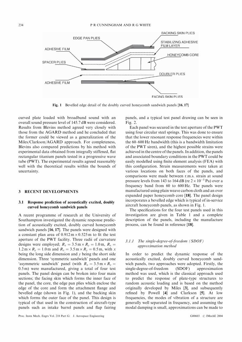
Soovere investigated the dynamic response of acous-tically excited carbon-fibre reinforced and Kevlarhoneycomb panels [13]. He extended existing orthotro-pic honeycomb panel theory, through coupled normalmode analysis, in order to predict the overall strain atboth the edges and the centre of the faces of the panels.His work was the first to investigate the effect of thebevelled edge closeout pan, an example of which isshown in Fig. 1, which was shown to increase theeffective shear stiffness of the honeycomb core by anorder of magnitude. Soovere showed both analyticallyand experimentally that, with laterally rigid edgesupports, the rotation of the bevelled edge introduceda linear dynamic membrane strain into the inner facesheet. He also found that the dominant contribution tohoneycomb panel damping was due to acoustic radia-tion, and for the carbon-fibre reinforced panels, thematerial damping was very low compared to the Kevlarreinforced panels. For singly curved sandwich panels, ithas been suggested that the strains at the centre of thepanel are higher on the convex face than on the concaveface.
An approximate analytical method for predicting theacoustic fatigue life of plates and shells using multi-modal analysis was developed by Blevins [14]. In hispaper, Blevins extended Miles’ approach [3] to highermodes and complex shapes. He developed methods forestimating the effects of finite acoustic wavelengths ontheir excitation. Blevins’ method is essentially a bridgebetween deterministic and statistical approaches and hisapproximations were most applicable to uniform plateand shell structures excited by a stationary (ergodic)sound field. The natural frequencies, mode shapes andthe relationship between modal deformation and modalstress are required as inputs in this method. Dampingand the magnitude of the applied pressures are alsorequired, although exact knowledge of the distributionof the applied surface pressures is not required, insteadan estimate of this distribution was used. For thisreason, the concept of joint acceptance was used inBlevins’ formulation. Since the evaluation of jointacceptance requires an estimate of the surface acousticpressure distributions, he suggested several approxima-tions for the shape of these distributions [14]. Blevinsused the mass-weighted structural mode shape approx-imation, from which the joint acceptance was calculatedto be unity. An improved approximation for the jointacceptance was developed by using sinusoids to modelthe structural and acoustic waveforms. A method wasthen given for calculating the acoustically induceddisplacements for any mode. In order to validate themethod, Blevins compared his results with thoseproduced by the AGARD [15] method, which is adesign guide formulated primarily from the work ofMiles [3] and Clarkson [5]. A flat plate and a singly
A REVIEW OF ANALYTICAL METHODS FOR AIRCRAFT STRUCTURES 233
G00603 # IMechE 2004 Proc. Instn Mech. Engrs Vol. 218 Part G: J. Aerospace Engineering
curved plate loaded with broadband sound with anoverall sound pressure level of 145.7 dB were considered.Results from Blevins method agreed very closely withthose from the AGARD method and he concluded thatthe former could be viewed as a generalization of theMiles/Clarkson/AGARD approach. For completeness,Blevins also compared predictions by his method withexperimental data obtained from integrally stiffened, flatrectangular titanium panels tested in a progressive wavetube (PWT). The experimental results agreed reasonablywell with the theoretical results within the bounds ofuncertainty.
3 RECENT DEVELOPMENTS
3.1 Response prediction of acoustically excited, doubly
curved honeycomb sandwich panels
A recent programme of research at the University ofSouthampton investigated the dynamic response predic-tion of acoustically excited, doubly curved honeycombsandwich panels [16, 17]. The panels were designed witha constant plan area of 0:912m60:525m to fit the testaperture of the PWT facility. Three radii of curvaturedesigns were employed; Rx ¼ 3:5m6Ry ¼ 1:0m, Rx ¼1:2m6Ry ¼ 1:0m and Rx ¼ 3:5m6Ry ¼ 0:5m, with xbeing the long side dimension and y being the short sidedimension. Three ‘symmetric sandwich’ panels and one‘asymmetric sandwich’ panel (with Rx ¼ 3:5m6Ry ¼0:5m) were manufactured, giving a total of four testpanels. The panel design can be broken into four mainsections; the facing skin which forms the inner face ofthe panel, the core, the edge pan plies which enclose theedge of the core and form the attachment flange andbevelled edge (shown in Fig. 1), and the backing skinwhich forms the outer face of the panel. This design istypical of that used in the construction of aircraft-typepanels such as intake barrel panels and flap fairing
panels, and a typical test panel drawing can be seen inFig. 2.
Each panel was secured in the test aperture of the PWTusing four circular steel springs. This was done to ensurethat the lower resonant response frequencies were withinthe 60–600Hz bandwidth (this is a bandwidth limitationof the PWT siren), and the highest possible strains wereachieved in the centre of the panels. In addition, the panelsand associated boundary conditions in the PWT could beeasily modelled using finite element analysis (FEA) withthis configuration. Strain measurements were taken atvarious locations on both faces of the panels, andcomparisons were made between r.m.s. strain at soundpressure levels from 143 to 164 dB (re 2610�5 Pa) over afrequency band from 60 to 600Hz. The panels weremanufactured using plain weave carbon cloth and an overexpanded paper honeycomb core [18]. The panel designincorporates a bevelled edge which is typical of in-serviceaircraft honeycomb panels, as shown in Fig. 1.
The specifications for the four test panels used in thisinvestigation are given in Table 1 and a completedescription of the panels, including the manufactureprocess, can be found in reference [18].
3.1.1 The single-degree-of-freedom (SDOF)approximation method
In order to predict the dynamic response of theacoustically excited, doubly curved honeycomb sand-wich panels, two approaches were adopted. Firstly, thesingle-degree-of-freedom (SDOF) approximationmethod was used, which is the classical approach usedto predict the response of plate-type structures torandom acoustic loading and is based on the methodoriginally developed by Miles [3], and subsequentlyrefined by Powell [4] and Clarkson [5]. At lowfrequencies, the modes of vibration of a structure aregenerally well separated in frequency, and assuming themodal damping is small, approximations can be made to
Fig. 1 Bevelled edge detail of the doubly curved honeycomb sandwich panels [16, 17]
P R CUNNINGHAM AND R G WHITE234
Proc. Instn Mech. Engrs Vol. 218 Part G: J. Aerospace Engineering G00603 # IMechE 2004
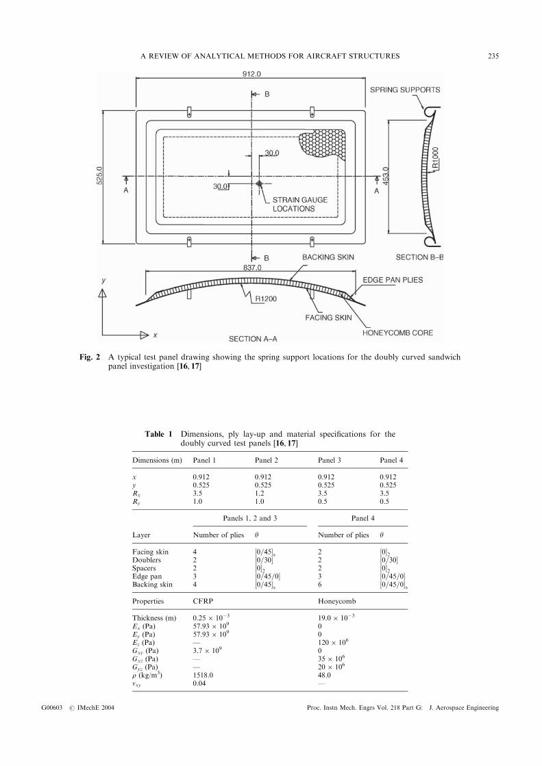
Fig. 2 A typical test panel drawing showing the spring support locations for the doubly curved sandwichpanel investigation [16, 17]
Table 1 Dimensions, ply lay-up and material specifications for thedoubly curved test panels [16, 17]
Dimensions (m) Panel 1 Panel 2 Panel 3 Panel 4
x 0.912 0.912 0.912 0.912y 0.525 0.525 0.525 0.525Rx 3.5 1.2 3.5 3.5Ry 1.0 1.0 0.5 0.5
Panels 1, 2 and 3 Panel 4
Layer Number of plies y Number of plies y
Facing skin 4 ½0=45�s 2 ½0�2Doublers 2 ½0=30� 2 ½0=30�Spacers 2 ½0�2 2 ½0�2Edge pan 3 ½0=45=0� 3 ½0=45=0�Backing skin 4 ½0=45�s 6 ½0=45=0�sProperties CFRP Honeycomb
Thickness (m) 0.256 10�3 19.06 10�3
Ex (Pa) 57.936 109 0Ey (Pa) 57.936 109 0Ez (Pa) — 1206 106
Gxy (Pa) 3.76 109 0Gxz (Pa) — 356 106
Gyz (Pa) — 206 106
r (kg/m3) 1518.0 48.0nxy 0.04 —
A REVIEW OF ANALYTICAL METHODS FOR AIRCRAFT STRUCTURES 235
G00603 # IMechE 2004 Proc. Instn Mech. Engrs Vol. 218 Part G: J. Aerospace Engineering
model each mode of vibration as a SDOF system:
€wwðtÞ þ 2znon _wwðtÞ þ o2nwðtÞ ¼ FnðtÞ ð2Þ
where FnðtÞ is the generalized force. AssumingFnðtÞ ¼ eiot and wðtÞ ¼ HðoÞeiot, then the substitutions_wwðtÞ ¼ ioHðoÞeiot and €wwðtÞ ¼ �o2HðoÞeiot can bemade in equation (2) to give
�o2 þ ð2znonÞioþ o2n
� �HðoÞ ¼ 1 ð3Þ
where t is the time, i is a complex number and HðoÞ isthe frequency response function.
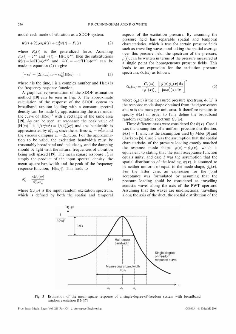
A graphical representation of the SDOF estimationmethod [19] can be seen in Fig. 3. The approximatecalculation of the response of the SDOF system tobroadband random loading with a constant spectraldensity can be made by approximating the area underthe curve of jHðoÞj2 with a rectangle of the same area[19]. As can be seen, at resonance the peak value ofjHðoÞj2 is 1=ðc2vo2
nÞ ¼ 1=ð4z2nk2s Þ and the bandwidth isapproximated by pznon since the stiffness ks ¼ o2
nm andthe viscous damping cv ¼ 2znonm. For the approxima-tion to be valid, the excitation bandwidth must bereasonably broadband and include on, and the dampingshould be light with the natural frequencies of vibrationbeing well spaced [19]. The mean square response s2w issimply the product of the input spectral density, themean square bandwidth and the peak of the frequencyresponse function, jHðoÞj2. This leads to
s2w ¼ pGnðoÞ4zno3
n
ð4Þ
where GnðoÞ is the input random excitation spectrum,which is defined by both the spatial and temporal
aspects of the excitation pressure. By assuming thepressure field has separable spatial and temporalcharacteristics, which is true for certain pressure fieldssuch as travelling waves, and taking the spatial averageover this pressure field, the spectrum of the pressure,pðtÞ, can be written in terms of the pressure measured ata single point for homogeneous pressure fields. Thisleads to an expression for the excitation pressurespectrum, GnðoÞ as follows:
GnðoÞ ¼ GpðoÞhc2ðxÞix
$cðxÞfnðxÞ dx$mf2
nðxÞ dx
" #2
ð5Þ
where GpðoÞ is the measured pressure spectrum, fnðxÞ isthe response mode shape obtained from the eigenvectorsand m is the mass per unit area. It therefore remains tospecify cðxÞ in order to fully define the broadbandrandom excitation spectrum GnðoÞ.
Three different cases were considered for cðxÞ. Case 1was the assumption of a uniform pressure distribution,cðxÞ ¼ 1, which is the assumption used by Miles [3] andClarkson [5]. Case 2 was the assumption that the spatialcharacteristics of the pressure loading exactly matchedthe response mode shape, cðxÞ ¼ fnðxÞ, which isequivalent to stating that the joint acceptance functionequals unity, and case 3 was the assumption that thespatial distribution of the loading, cðxÞ, is assumed tobe neither uniform or equal to the mode shape, fnðxÞ.For the latter case, an expression for the jointacceptance was formulated by assuming that thepressure loading could be considered as travellingacoustic waves along the axis of the PWT aperture.Assuming that the waves are unidirectional travellingalong the axis of the duct, the spatial distribution of the
Fig. 3 Estimation of the mean-square response of a single-degree-of-freedom system with broadbandrandom excitation [16, 17]
P R CUNNINGHAM AND R G WHITE236
Proc. Instn Mech. Engrs Vol. 218 Part G: J. Aerospace Engineering G00603 # IMechE 2004
pressure loading can be written in the form
Hðx, f Þ ¼ e�ikax ð6Þ
where ka ¼ on=c is the acoustic wavenumber, on is thenatural frequency of vibration of the relevant mode ofthe test panel ðon ¼ 2pfnÞ and c is the speed of sound,
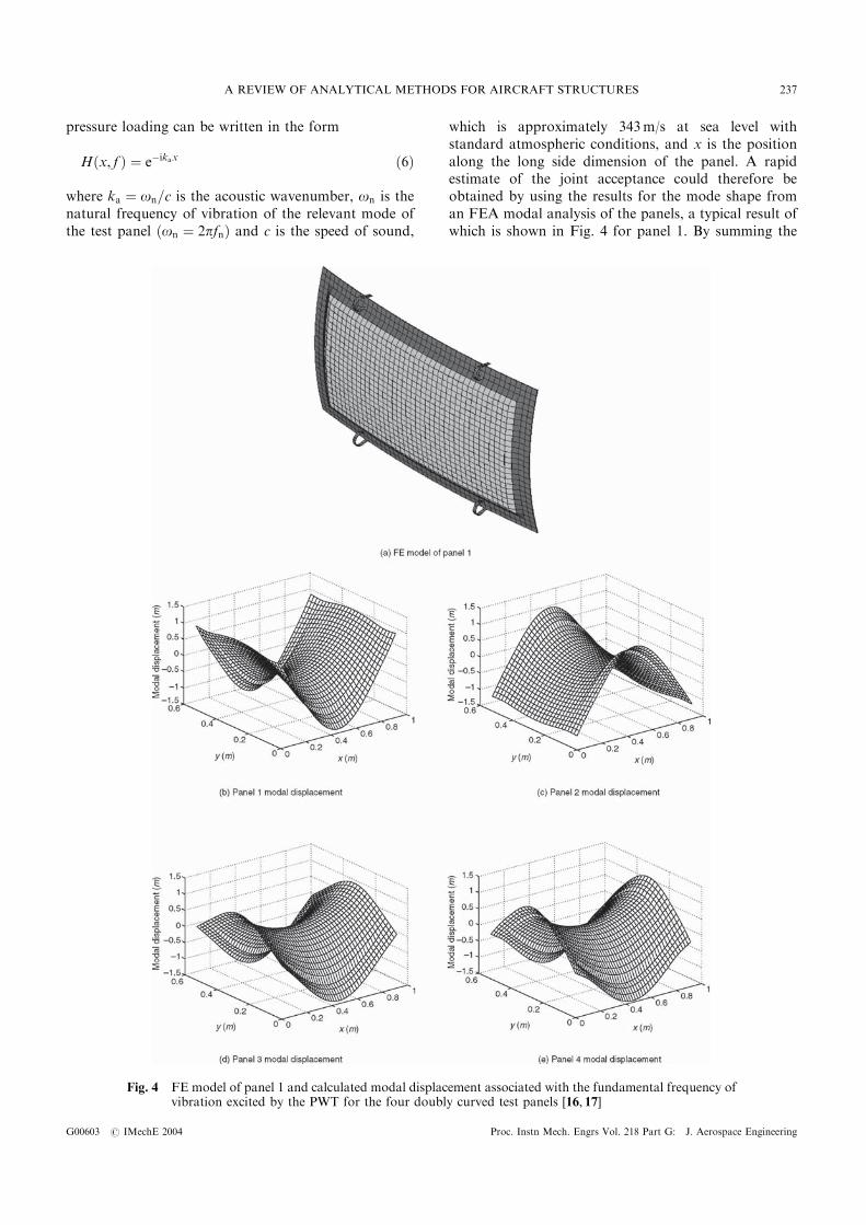
which is approximately 343m/s at sea level withstandard atmospheric conditions, and x is the positionalong the long side dimension of the panel. A rapidestimate of the joint acceptance could therefore beobtained by using the results for the mode shape froman FEA modal analysis of the panels, a typical result ofwhich is shown in Fig. 4 for panel 1. By summing the
Fig. 4 FE model of panel 1 and calculated modal displacement associated with the fundamental frequency ofvibration excited by the PWT for the four doubly curved test panels [16, 17]
A REVIEW OF ANALYTICAL METHODS FOR AIRCRAFT STRUCTURES 237
G00603 # IMechE 2004 Proc. Instn Mech. Engrs Vol. 218 Part G: J. Aerospace Engineering
modal displacemements for the mode shape in questionand multiplying by the area of the panel divided by thenumber of nodes, an estimate of the integral of the modeshape is obtained. Thus the joint acceptance functionused was [17]
J2n ¼
PNj¼1
ffngje�ikaxj
����������2
PNj¼1
je�ikaxj j2 PNj¼1
ffng2jð7Þ
where ffngj is the modal displacement at each node j forthe mode shape in question, xj is the nodal coordinate inthe x direction (along the long side of the panel) for eachnode j and N is the number of nodes in the FEA model.
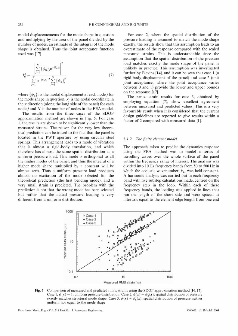
The results from the three cases of the SDOFapproximation method are shown in Fig. 5. For case1, the results are shown to be significantly lower than themeasured strains. The reason for the very low theore-tical prediction can be traced to the fact that the panel islocated in the PWT aperture by using circular steelsprings. This arrangement leads to a mode of vibrationthat is almost a rigid-body translation, and whichtherefore has almost the same spatial distribution as auniform pressure load. This mode is orthogonal to allthe higher modes of the panel, and thus the integral of ahigher mode shape multiplied by a constant will bealmost zero. Thus a uniform pressure load producesalmost no excitation of the mode selected for thetheoretical prediction (the first bending mode), and avery small strain is predicted. The problem with theprediction is not that the wrong mode has been selectedbut rather that the actual pressure loading is verydifferent from a uniform distribution.
For case 2, where the spatial distribution of thepressure loading is assumed to match the mode shapeexactly, the results show that this assumption leads to anoverestimate of the response compared with the scaledmeasured strains. This is understandable since theassumption that the spatial distribution of the pressureload matches exactly the mode shape of the panel isunlikely in practice. This assumption was investigatedfurther by Blevins [14], and it can be seen that case 1 (arigid-body displacement of the panel) and case 2 (unitjoint acceptance, where the joint acceptance variesbetween 0 and 1) provide the lower and upper boundson the response [17].
The r.m.s. strain results for case 3, obtained byemploying equation (7), show excellent agreementbetween measured and predicted values. This is a veryfavourable result when it is considered that the currentdesign guidelines are reported to give results within afactor of 2 compared with measured data [1].
3.1.2 The finite element model
The approach taken to predict the dynamics responseusing the FEA method was to model a series oftravelling waves over the whole surface of the panelwithin the frequency range of interest. The analysis wasdivided into 10Hz frequency bands from 50 to 500Hz inwhich the acoustic wavenumber, ka, was held constant.A harmonic analysis was carried out in each frequencyband with five substep calculations made, centred on thefrequency step in the loop. Within each of thesefrequency bands, the loading was applied in lines thatran the length of the short side and were spaced atintervals equal to the element edge length from one end
Fig. 5 Comparison of measured and predicted r.m.s. strains using the SDOF approximation method [16, 17].Case 1, cðxÞ ¼ 1, uniform pressure distribution. Case 2, cðxÞ ¼ fnðxÞ, spatial distribution of pressureexactly matches structural mode shape. Case 3, cðxÞ 6¼ fnðxÞ, spatial distribution of pressure neitheruniform nor equal to the mode shape
P R CUNNINGHAM AND R G WHITE238
Proc. Instn Mech. Engrs Vol. 218 Part G: J. Aerospace Engineering G00603 # IMechE 2004
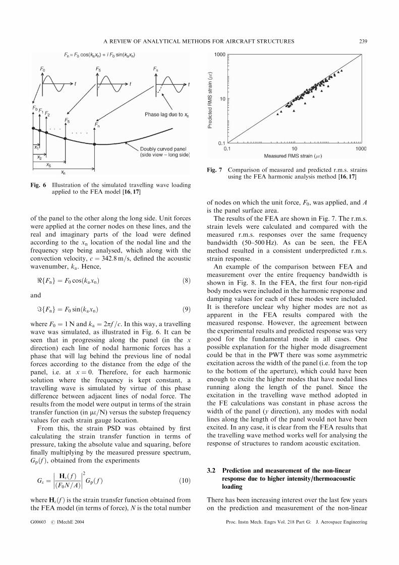
of the panel to the other along the long side. Unit forceswere applied at the corner nodes on these lines, and thereal and imaginary parts of the load were definedaccording to the xn location of the nodal line and thefrequency step being analysed, which along with theconvection velocity, c ¼ 342:8m=s, defined the acousticwavenumber, ka. Hence,
<fFng ¼ F0 cosðkaxnÞ ð8Þ
and
=fFng ¼ F0 sinðkaxnÞ ð9Þ
where F0 ¼ 1N and ka ¼ 2pf =c. In this way, a travellingwave was simulated, as illustrated in Fig. 6. It can beseen that in progressing along the panel (in the xdirection) each line of nodal harmonic forces has aphase that will lag behind the previous line of nodalforces according to the distance from the edge of thepanel, i.e. at x ¼ 0. Therefore, for each harmonicsolution where the frequency is kept constant, atravelling wave is simulated by virtue of this phasedifference between adjacent lines of nodal force. Theresults from the model were output in terms of the straintransfer function (in me=N) versus the substep frequencyvalues for each strain gauge location.
From this, the strain PSD was obtained by firstcalculating the strain transfer function in terms ofpressure, taking the absolute value and squaring, beforefinally multiplying by the measured pressure spectrum,Gpðf Þ, obtained from the experiments
Ge ¼ Heð f ÞðF0N=AÞ����
����2
Gpð f Þ ð10Þ
whereHeðf Þ is the strain transfer function obtained fromthe FEA model (in terms of force), N is the total number
of nodes on which the unit force, F0, was applied, and Ais the panel surface area.
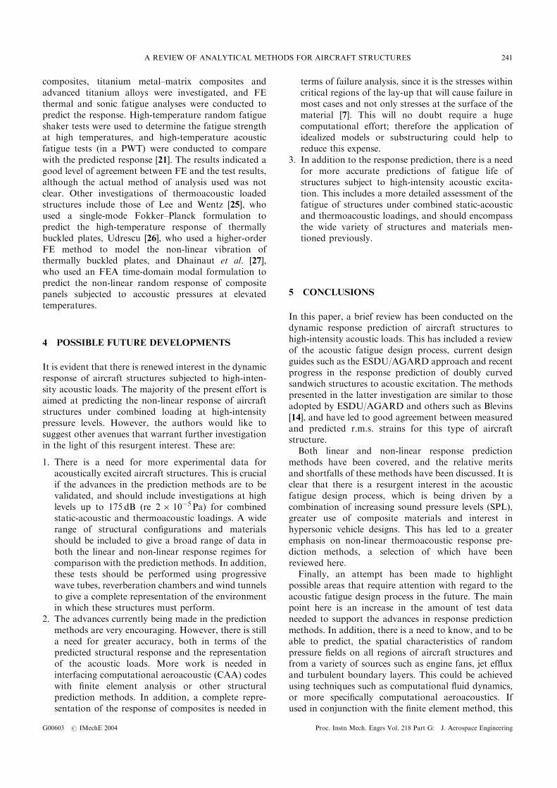
The results of the FEA are shown in Fig. 7. The r.m.s.strain levels were calculated and compared with themeasured r.m.s. responses over the same frequencybandwidth (50–500Hz). As can be seen, the FEAmethod resulted in a consistent underpredicted r.m.s.strain response.
An example of the comparison between FEA andmeasurement over the entire frequency bandwidth isshown in Fig. 8. In the FEA, the first four non-rigidbody modes were included in the harmonic response anddamping values for each of these modes were included.It is therefore unclear why higher modes are not asapparent in the FEA results compared with themeasured response. However, the agreement betweenthe experimental results and predicted response was verygood for the fundamental mode in all cases. Onepossible explanation for the higher mode disagreementcould be that in the PWT there was some asymmetricexcitation across the width of the panel (i.e. from the topto the bottom of the aperture), which could have beenenough to excite the higher modes that have nodal linesrunning along the length of the panel. Since theexcitation in the travelling wave method adopted inthe FE calculations was constant in phase across thewidth of the panel (y direction), any modes with nodallines along the length of the panel would not have beenexcited. In any case, it is clear from the FEA results thatthe travelling wave method works well for analysing theresponse of structures to random acoustic excitation.
3.2 Prediction and measurement of the non-linear
response due to higher intensity/thermoacoustic
loading
There has been increasing interest over the last few yearson the prediction and measurement of the non-linear
Fig. 6 Illustration of the simulated travelling wave loadingapplied to the FEA model [16, 17]
Fig. 7 Comparison of measured and predicted r.m.s. strainsusing the FEA harmonic analysis method [16, 17]
A REVIEW OF ANALYTICAL METHODS FOR AIRCRAFT STRUCTURES 239
G00603 # IMechE 2004 Proc. Instn Mech. Engrs Vol. 218 Part G: J. Aerospace Engineering

response of structures due to high intensity loading. Thishas been driven, in part, by the increasing soundpressure levels being predicted and experienced by thelatest generation of ASTOVL strike fighters, coupledwith greater use of lighter, stiffer composite structures.In addition, with advanced stealth technology, stores arebeing located internally, which is presenting a newproblem in the form of cavity noise and the highintensity loads which are being experienced within thebays that house the stores of these aircraft. Inconjunction with higher sound pressure levels, recentdevelopments in acoustic fatigue research have alsoconcentrated on combined thermal-acoustic environ-ments, which are being driven by studies of possiblehypersonic vehicle designs [20, 21].
Green and Killey [22] highlighted the fact that thecurrent adopted method of using linear vibration theoryfor determinig fatigue life, which assumes that thepressure field is fully correlated over the surface area ofthe structure, becomes increasingly unsatisfactory whengeometric non-linearities occur due to high soundpressure levels. They also noted that the excitation willgenerally be out-of-phase over the structure due tocomplex aerodynamic effects [22]. A time domainMonte Carlo (TDMC) technique was used to modelthe multi-modal vibrations of aircraft structures, whichwas implemented by interfacing with a conventionalFEA code. Analyses were carried out for a simple flatplate with and without combined loads (i.e. highintensity acoustic pressures plus static loads), and theresults indicated that the overall predicted stress levelswere better than those between predictions based onlinear or equivalently linear theory and test [22]. The
downside of the approach was that the TDMC runstook a significant amount of computer time to carry out[22], but another advantage was that the ‘snap-through’phenomenon can be modelled using the TDMC/FEAapproach, which is not possible with existing methods.Other work in this area includes that of Rizzi andMuravyov [23], who used the equivalent linearization(EL) approach to analyse the random vibration ofgeometrically non-linear multiple-degree-of-freedomstructures. The results from this analysis, which is astatistical linearization method, were compared withresults from an FE numerical analysis. The authors [23]noted that the EL method has potential advantages overconventional linear analyses when computing the fatiguelife based on r.m.s. stress levels; however, this methodrequires careful investigation when conducting a fatiguelife calculation based on the EL-derived PSD response[23]. Finally, for a non-linear response prediction,McEwan et al. [24] extended an FE-based modalapproach to the case of multi-modal, non-linear beamvibrations. The method was used to model isotropicbeams with simply supported and fully clampedboundary conditions, with free vibration and steadystate harmonic excitation considered. The work showedgood agreement compared with a standard directintegration FE approach, with considerable savings incomputational expense.
For the case of combined thermoacoustic loading,recent studies include that of Holehouse [21] whoreported on an experimental and analytical programmeconcerned with the structural response and fatiguecharacteristics of skin panels for a generic hypersonicflight vehicle. Carbon–carbon, silicon–carbide refactory
Fig. 8 Comparison of predicted FE (–) and measured (- -) strain PSD for the inner centre gauge (x-wise),panel 2 [16, 17]
P R CUNNINGHAM AND R G WHITE240
Proc. Instn Mech. Engrs Vol. 218 Part G: J. Aerospace Engineering G00603 # IMechE 2004
composites, titanium metal–matrix composites andadvanced titanium alloys were investigated, and FEthermal and sonic fatigue analyses were conducted topredict the response. High-temperature random fatigueshaker tests were used to determine the fatigue strengthat high temperatures, and high-temperature acousticfatigue tests (in a PWT) were conducted to comparewith the predicted response [21]. The results indicated agood level of agreement between FE and the test results,although the actual method of analysis used was notclear. Other investigations of thermoacoustic loadedstructures include those of Lee and Wentz [25], whoused a single-mode Fokker–Planck formulation topredict the high-temperature response of thermallybuckled plates, Udrescu [26], who used a higher-orderFE method to model the non-linear vibration ofthermally buckled plates, and Dhainaut et al. [27],who used an FEA time-domain modal formulation topredict the non-linear random response of compositepanels subjected to accoustic pressures at elevatedtemperatures.
4 POSSIBLE FUTURE DEVELOPMENTS
It is evident that there is renewed interest in the dynamicresponse of aircraft structures subjected to high-inten-sity acoustic loads. The majority of the present effort isaimed at predicting the non-linear response of aircraftstructures under combined loading at high-intensitypressure levels. However, the authors would like tosuggest other avenues that warrant further investigationin the light of this resurgent interest. These are:
1. There is a need for more experimental data foracoustically excited aircraft structures. This is crucialif the advances in the prediction methods are to bevalidated, and should include investigations at highlevels up to 175 dB (re 26 10�5 Pa) for combinedstatic-acoustic and thermoacoustic loadings. A widerange of structural configurations and materialsshould be included to give a broad range of data inboth the linear and non-linear response regimes forcomparison with the prediction methods. In addition,these tests should be performed using progressivewave tubes, reverberation chambers and wind tunnelsto give a complete representation of the environmentin which these structures must perform.
2. The advances currently being made in the predictionmethods are very encouraging. However, there is stilla need for greater accuracy, both in terms of thepredicted structural response and the representationof the acoustic loads. More work is needed ininterfacing computational aeroacoustic (CAA) codeswith finite element analysis or other structuralprediction methods. In addition, a complete repre-sentation of the response of composites is needed in
terms of failure analysis, since it is the stresses withincritical regions of the lay-up that will cause failure inmost cases and not only stresses at the surface of thematerial [7]. This will no doubt require a hugecomputational effort; therefore the application ofidealized models or substructuring could help toreduce this expense.
3. In addition to the response prediction, there is a needfor more accurate predictions of fatigue life ofstructures subject to high-intensity acoustic excita-tion. This includes a more detailed assessment of thefatigue of structures under combined static-acousticand thermoacoustic loadings, and should encompassthe wide variety of structures and materials men-tioned previously.
5 CONCLUSIONS
In this paper, a brief review has been conducted on thedynamic response prediction of aircraft structures tohigh-intensity acoustic loads. This has included a reviewof the acoustic fatigue design process, current designguides such as the ESDU/AGARD approach and recentprogress in the response prediction of doubly curvedsandwich structures to acoustic excitation. The methodspresented in the latter investigation are similar to thoseadopted by ESDU/AGARD and others such as Blevins[14], and have led to good agreement between measuredand predicted r.m.s. strains for this type of aircraftstructure.
Both linear and non-linear response predictionmethods have been covered, and the relative meritsand shortfalls of these methods have been discussed. It isclear that there is a resurgent interest in the acousticfatigue design process, which is being driven by acombination of increasing sound pressure levels (SPL),greater use of composite materials and interest inhypersonic vehicle designs. This has led to a greateremphasis on non-linear thermoacoustic response pre-diction methods, a selection of which have beenreviewed here.
Finally, an attempt has been made to highlightpossible areas that require attention with regard to theacoustic fatigue design process in the future. The mainpoint here is an increase in the amount of test dataneeded to support the advances in response predictionmethods. In addition, there is a need to know, and to beable to predict, the spatial characteristics of randompressure fields on all regions of aircraft structures andfrom a variety of sources such as engine fans, jet effluxand turbulent boundary layers. This could be achievedusing techniques such as computational fluid dynamics,or more specifically computational aeroacoustics. Ifused in conjunction with the finite element method, this
A REVIEW OF ANALYTICAL METHODS FOR AIRCRAFT STRUCTURES 241
G00603 # IMechE 2004 Proc. Instn Mech. Engrs Vol. 218 Part G: J. Aerospace Engineering

would provide the designer with a very powerfulresponse prediction tool.
ACKNOWLEDGEMENT
The authors would like to acknowledge the Engineeringand Physical Sciences Research Council (EPSRC), whofunded the work concerned with the response predictionof acoustically excited, doubly curved sandwich struc-tures under Grant GR/K80600.
REFERENCES
1 Clarkson, B. L. Review of sonic fatigue technology. NASA
Technical Report CP-4587, 1994.
2 McGowan, P. R. Structural design for acoustic fatigue.
Technical Report TDR-63-820, ASD, October 1963.
3 Miles, J. W. On structural fatigue under random loading.
J. Aeronaut. Sci., 1954, 21, 753–762.
4 Powell, A. On the fatigue failure of structures due to
vibrations excited by random pressure fields. J. Acoust.
Soc. Am., 1958, 30(12), 1130–1135.
5 Clarkson, B. L. Stresses in skin panels subjected to random
acoustic loading. Aeronaut. J.R. Aeronaut. Soc., 1968, 72,
1000–1010.
6 Engineering Sciences Data Unit Design Guide Series:
Vibration and Acoustic Fatigue, Vols 1–7, August 2001,
Supplement level 48 (ESDU International, London).
7 White, R. G. Developments in the acoustic fatigue design
process for composite aircraft structures. Composite
Structs, 1990, 16, 171–192.
8 Rudder, F. F. and Plumblee, H. E. Sonic fatigue design
guide for military aircraft. Technical Report AFFDL-TR-
74-112, Acoustics and Vibration Associates, Atlanta,
Georgia, Febrary 1975.
9 White, R. G. A comparison of some statistical properties of
the responses of aluminium alloy and CFRP plates to
acoustic excitation. Composites, 1978, 9, 251–258.
10 Wolfe, N. D. and Jacobson, M. J. Design and sonic fatigue
characteristics of composite material components. In
Symposium on Acoustic Fatigue, Toulouse, France, 1972,
AGARD Conference Proceedings 113.
11 White, R. G. and Mousley, R. F. Dynamic response of
CFRP plates under the action of random acoustic loading.
In Proceedings of the Fourth International Conference on
Composite Structures, Paisley College of Technology, 1987,
pp. 1519–1535.
12 Drew, R. C. and White, R. G. An experimental investiga-
tion into damage propogation and its effects upon dynamic
properties in CFRP composite material. In Proceedings of
the Fourth International Conference on Composite Struc-
tures, Paisley College of Technology, 1987, pp. 245–256.
13 Soovere, J. Random vibration analysis of stiffened
honeycomb panels with beveled edges. Am. Inst. Aeronaut,
Astronaut. J. Aircr., 1986, 23(6), 537–544.
14 Blevins, R. D. An approximate method for sonic fatigue
analysis of plates and shells. J. Sound Vibr., 1989, 129(1),
51–71.
15 Thompson, A. G. R. and Lambert, R. F. The estimation of
RMS stresses in stiffened skin panels subjected to random
acoustic loading. Technical Report Section 5, AGARD-
AG-162, Advisory Group for Aerospace Research and
Development, NATO, November 1972.
16 Cunningham, P. R. and White, R. G. Dynamic response
prediction of doubly curved honeycomb sandwich panels
to random acoustic excitation. Part 1: experimental study.
J. Sound Vibr., July 2003, 264(2), 579–603.
17 Cunningham, P. R., Langley, R. S. and White, R. G.
Dynamic response prediction of doubly curved honeycomb
sandwich panels to random acoustic excitation. Part 2:
theoretical study. J. Sound Vibr., July 2003, 264(2), 605–
637.
18 Cunningham, P. R., White, R. G. and Aglietti, G. S. The
effects of various design parameters on the free vibration of
doubly curved composite sandwich panels. J. Sound Vibr.,
2000, 230(3), 617–648.
19 Norton, M. P. Fundamentals of Noise and Vibration
Analysis for Engineers, 1996 (Cambridge University Press,
Cambridge).
20 Blevins, R. D., Holehouse, I. and Wentz, K. R. Thermo-
acoustic loads and fatigue of hypersonic vehicle skin
panels. J. Aircr., 1993, 30, 971–978.
21 Holehouse, I. Sonic fatigue characteristics of high tempera-
ture materials and structures for hypersonic vehicle
applications. In Proceedings of the 6th International
Conference on Recent Advances in Structural Dynamics,
University of Southampton, July 1997, Vol. 2, pp. 935–949.
22 Green, P. D. and Killey, A. Time domain dynamic finite
element modelling in acoustic fatigue design. In Proceed-
ings of the 6th International Conference on Recent
Advances in Structural Dynamics, University of South-
ampton, July 1997, Vol. 2, pp. 1007–1026.
23 Rizzi, S. A. and Muravyov, A. A. Comparison of nonlinear
random response using equivalent linearization and
numerical simulation. In Proceedings of the 7th Interna-
tional Conference on Recent Advances in Structural
Dynamics, University of Southampton, July 2000, Vol. 2,
pp. 833–846.
24 McEwan, M. I., Wright, J. R., Cooper, J. E. and Leung, A.
Y. T. A combined modal/finite element analysis technique
for the dynamic response of a non-linear beam to harmonic
excitation. J. Sound Vibr., 2001, 243(4), 601–624.
25 Lee, J. and Wentz, K. R. Strain power spectra of a
thermally buckled plate in random vibration. In Proceed-
ings of the 6th International Conference on Recent
Advances in Structural Dynamics, University of South-
ampton, July 1997, Vol. 2, pp. 903–917.
26 Udrescu, R. Nonlinear vibrations of thermally buckled
panels. In Proceedings of the 7th International Conference
on Recent Advances in Structural Dynamics, University of
Southampton, July 2000, Vol. 2, pp. 757–768.
27 Dhainaut, J. M., Duan, B., Mei, C., Spottswood, S. M. and
Wolfe, H. F. Non-linear response of composite panels to
random excitations at elevated temperatures. In Proceed-
ings of the 7th International Conference on Recent
Advances in Structural Dynamics, University of South-
ampton, July 2000, Vol. 2, pp. 769–784.
P R CUNNINGHAM AND R G WHITE242
Proc. Instn Mech. Engrs Vol. 218 Part G: J. Aerospace Engineering G00603 # IMechE 2004
Related Documents