Abstract—Robotics brings together several very different engineering areas and skills. There are various types of robot such as humanoid robot, mobile robots, remotely operated vehicles, modern autonomous robots etc. This survey paper advocates the operation of a robotic car (remotely operated vehicle) that is controlled by a mobile phone (communicate on a large scale over a large distance even from different cities). The person makes a call to the mobile phone placed in the car. In the case of a call, if any one of the button is pressed, a tone equivalent to the button pressed is heard at the other end of the call. This tone is known as DTMF (Dual Tone Multiple Frequency). The car recognizes this DTMF tone with the help of the phone stacked in the car. The received tone is processed by the Arduino microcontroller. The microcontroller is programmed to acquire a decision for any given input and outputs its decision to motor drivers in order to drive the motors in the forward direction or backward direction or left or right direction. The mobile phone that makes a call to cell phone stacked in the car act as a remote Keywords—Arduino Micro-controller, Arduino UNO, DTMF, Mobile phone, Robotic car. I. INTRODUCTION A. Robot OR many people robot is a machine that imitates a human—like androids in Star Wars, Star Trek and Terminator. However much of these robots incarcerate our thoughts, such robots still only dwell in science fiction. Still, it is impossible to give a robot enough 'common sense' to reliably interact with a dynamic world. Today, robotics is a rapidly growing field in researching, designing, and building new robots practical purpose, whether domestically, commercially, or militarily. Many robots help humans by doing jobs such as defusing bombs, mines and exploring shipwrecks. B. Types of Robots by Application • Industrial robots are robots used in an industrial manufacturing environment. Generally these are articulated arms specifically developed for applications such as material handling, painting, welding and others. If we judge this by an application, it also includes some automated guided vehicles and other robots. • Domestic or household robots are used at home. This type of robots includes several quite different devices such as Mr. C. Rajan, Assistant Professor, is with the Dept. of. IT, K. S. Rangasamy College of Technology, Tamil Nadu, India (phone: 9865090665; e-mail: [email protected]). Ms. B. Megala, Ms. A. Nandhini, UG Scholar, are with the Dept. of. IT, K. S. Rangasamy College of Technology, Tamil Nadu, India (phone: 8870278513; e-mail: [email protected]). robotic pool cleaners, robotic vacuum cleaners, gutter cleaners, sweepers and other robots that can do different chores. And also some surveillance and telepresence robots could be regarded as household robots if used in that environment. • Medical robots are used in medicine and medical institutions. And also in some automated guided vehicles and lifting aides. • Service robots are the robots that don’t fall into other types by usage. These might be robots used for research, different data gathering robots, etc. • Military robots are used in military. This kind of robots includes different transportation robots, bomb disposal robots and reconnaissance drones. Robots initially created for military purposes can be used in search and rescue, law enforcement, and other related fields. • Entertainment robots are robots used for entertainment. It is a very broad category. It begins with toy robots such as robosapien or the running alarm clock and ends with real heavyweights such as articulated robot arms used as motion simulators. • Space robots include robots used on the International Space Station, Canadarm which was used in Shuttles, as well as Mars rovers and other robots used in space. • Hobby and competition robots are that you create. Sumo- bots, line followers, robots made just for fun and robots made for competition [15]. C. Robotic Vehicle and DTMF Technology A remote control vehicle (RCV) is defined as any mobile device that is controlled by a means that does not restrict its motion with an origin external to a device. This is commonly a radio control device, infrared controller or a cable between control and vehicle. A RCV is at all times controlled by a human and takes no positive action autonomously [2]. Mostly wireless-controlled robots use RF circuits, which have the drawbacks of limited frequency, limited control and limited frequency range. Since here cell phone is used to control the operation of the robot, it can overcome these limitations. The cell phone signal has a wide range over the surface that’s why robot can be operated from far away without disturbance and interference with other signals. The control action of robot includes three parts Perception, Processing and Action. Generally, the preceptors are the sensors mounted on the robot, processing can be done by the on-board microcontroller or processor, and then the action is performed using motors [26]. A Review: Comparative Analysis of Arduino Micro Controllers in Robotic Car C. Rajan, B. Megala, A. Nandhini, C. Rasi Priya F World Academy of Science, Engineering and Technology International Journal of Mechanical, Aerospace, Industrial and Mechatronics Engineering Vol:9, No:2, 2015 365 International Scholarly and Scientific Research & Innovation 9(2) 2015 International Science Index Vol:9, No:2, 2015 waset.org/Publication/10001073

Welcome message from author
This document is posted to help you gain knowledge. Please leave a comment to let me know what you think about it! Share it to your friends and learn new things together.
Transcript
Abstract—Robotics brings together several very different engineering areas and skills. There are various types of robot such as humanoid robot, mobile robots, remotely operated vehicles, modern autonomous robots etc. This survey paper advocates the operation of a robotic car (remotely operated vehicle) that is controlled by a mobile phone (communicate on a large scale over a large distance even from different cities). The person makes a call to the mobile phone placed in the car. In the case of a call, if any one of the button is pressed, a tone equivalent to the button pressed is heard at the other end of the call. This tone is known as DTMF (Dual Tone Multiple Frequency). The car recognizes this DTMF tone with the help of the phone stacked in the car. The received tone is processed by the Arduino microcontroller. The microcontroller is programmed to acquire a decision for any given input and outputs its decision to motor drivers in order to drive the motors in the forward direction or backward direction or left or right direction. The mobile phone that makes a call to cell phone stacked in the car act as a remote
Keywords—Arduino Micro-controller, Arduino UNO, DTMF, Mobile phone, Robotic car.
I. INTRODUCTION
A. Robot
OR many people robot is a machine that imitates a
human—like androids in Star Wars, Star Trek and
Terminator. However much of these robots incarcerate our
thoughts, such robots still only dwell in science fiction. Still, it
is impossible to give a robot enough 'common sense' to reliably
interact with a dynamic world.
Today, robotics is a rapidly growing field in researching,
designing, and building new robots practical purpose, whether
domestically, commercially, or militarily. Many robots help
humans by doing jobs such as defusing bombs, mines and
exploring shipwrecks.
B. Types of Robots by Application
• Industrial robots are robots used in an industrial
manufacturing environment. Generally these are
articulated arms specifically developed for applications
such as material handling, painting, welding and others. If
we judge this by an application, it also includes some
automated guided vehicles and other robots.
• Domestic or household robots are used at home. This type
of robots includes several quite different devices such as
Mr. C. Rajan, Assistant Professor, is with the Dept. of. IT, K. S.
Rangasamy College of Technology, Tamil Nadu, India (phone: 9865090665; e-mail: [email protected]). Ms. B. Megala, Ms. A. Nandhini, UG Scholar, are with the Dept. of. IT, K.
S. Rangasamy College of Technology, Tamil Nadu, India (phone: 8870278513; e-mail: [email protected]).
robotic pool cleaners, robotic vacuum cleaners, gutter
cleaners, sweepers and other robots that can do different
chores. And also some surveillance and telepresence
robots could be regarded as household robots if used in
that environment.
• Medical robots are used in medicine and medical
institutions. And also in some automated guided vehicles
and lifting aides.
• Service robots are the robots that don’t fall into other types
by usage. These might be robots used for research,
different data gathering robots, etc.
• Military robots are used in military. This kind of robots
includes different transportation robots, bomb disposal
robots and reconnaissance drones. Robots initially created
for military purposes can be used in search and rescue, law
enforcement, and other related fields.
• Entertainment robots are robots used for entertainment. It
is a very broad category. It begins with toy robots such as
robosapien or the running alarm clock and ends with real
heavyweights such as articulated robot arms used as
motion simulators.
• Space robots include robots used on the International
Space Station, Canadarm which was used in Shuttles, as
well as Mars rovers and other robots used in space.
• Hobby and competition robots are that you create. Sumo-
bots, line followers, robots made just for fun and robots
made for competition [15].
C. Robotic Vehicle and DTMF Technology
A remote control vehicle (RCV) is defined as any mobile
device that is controlled by a means that does not restrict its
motion with an origin external to a device. This is commonly a
radio control device, infrared controller or a cable between
control and vehicle. A RCV is at all times controlled by a
human and takes no positive action autonomously [2]. Mostly
wireless-controlled robots use RF circuits, which have the
drawbacks of limited frequency, limited control and limited
frequency range. Since here cell phone is used to control the
operation of the robot, it can overcome these limitations. The
cell phone signal has a wide range over the surface that’s why
robot can be operated from far away without disturbance and
interference with other signals. The control action of robot
includes three parts Perception, Processing and Action.
Generally, the preceptors are the sensors mounted on the robot,
processing can be done by the on-board microcontroller or
processor, and then the action is performed using motors [26].
A Review: Comparative Analysis of Arduino Micro Controllers in Robotic Car
C. Rajan, B. Megala, A. Nandhini, C. Rasi Priya
F
World Academy of Science, Engineering and TechnologyInternational Journal of Mechanical, Aerospace, Industrial and Mechatronics Engineering Vol:9, No:2, 2015
365International Scholarly and Scientific Research & Innovation 9(2) 2015
Inte
rnat
iona
l Sci
ence
Ind
ex V
ol:9
, No:
2, 2
015
was
et.o
rg/P
ublic
atio
n/10
0010
73
D. History of DTMF
Before DTMF was created, telephone networks used a
dialing system called Decadic (also known as Pulse Dial). The
Decadic system was used widely in modern telephone
networks to dial numbers which could be entered by the
telephone companies’ users. The Decadic (Pulse Dialing)
system used a series of clicks (which could be heard through
the speaker of the phone) to dial the numbers which were
dialed via a keypad or rotary dial. The clicking sounds were
the connection of the phone line being connected, disconnected
and reconnected over again in a certain pattern. The Decadic
(Pulse Dialing) system was very useful, but limited to the local
exchange connections, demanding an operator to connect long
distance calls. In late years of 1950, DTMF was being
developed at Bell Labs for the purpose of allowing tone signals
to dial long distance numbers, which could be potentially be
dialed not only via standard wire networks, but also through
radio links and or satellites [1].
E. DTMF Technology
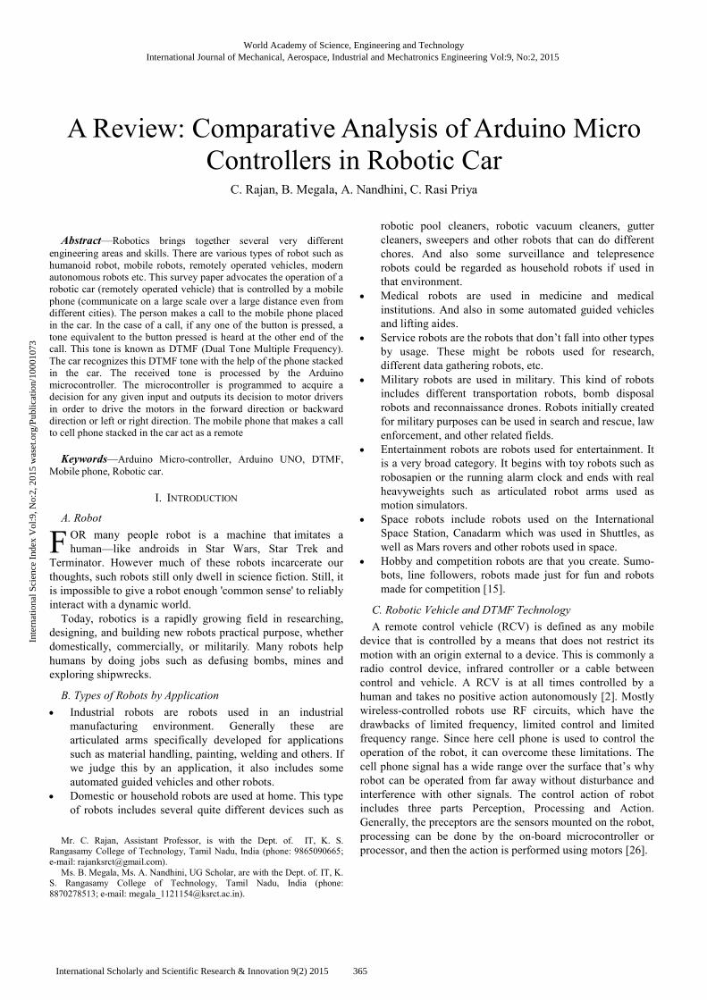
DTMF stands for Dual Tone Multiple Frequency. DTMF is
a term which is used in the telephone industry. DTMF
generation is a composite audio signal of two tones between
the frequency of 697Hz and 1633Hz. The DTMF keypad is
arranged in such a way that each row will have its own unique
tone frequency and also each column will have its own unique
tone. Fig.1 is a representation of the typical DTMF keypad and
the associated row/column frequencies. When any of the keys
like "1", "2", "*", "#" etc., is pressed, exact code is transmitted.
This code consists of two frequencies among which first one is
a higher frequency and the second one is a lower frequency as
shown in Fig. 1 [3], [20]. The engineers had envisioned phones
being used to access computers, and surveyed the number of
companies to see what they would need for this task. This lead
to the addition of the number sign (#, sometimes called
'octothorpe' in this context) and the asterisk or "star" (*) keys
as well as a group of keys for menu selection: A, B, C and D.
The levels of priority available were Flash Override (A), Flash
(B), Immediate (C), and Priority (D), with Flash Override
being the highest priority [19].
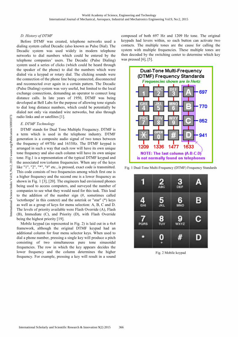
Mobile keypad (as represented in Fig. 2) is laid out in a 4x4
framework, although the original DTMF keypad had an
additional column for four menu selector keys. When used to
dial a phone number, pressing a single key will produce a pitch
consisting of two simultaneous pure tone sinusoidal
frequencies. The row in which the key appears decides the
lower frequency and the column determines the higher
frequency. For example, pressing a key will result in a sound
composed of both 697 Hz and 1209 Hz tone. The original
keypads had levers within, so each button can activate two
contacts. The multiple tones are the cause for calling the
system with multiple frequencies. These multiple tones are
then decoded by the switching center to determine which key
was pressed [6], [5].
Fig. 1 Dual-Tone Multi-Frequency (DTMF) Frequency Standards
Fig. 2 Mobile keypad
World Academy of Science, Engineering and TechnologyInternational Journal of Mechanical, Aerospace, Industrial and Mechatronics Engineering Vol:9, No:2, 2015
366International Scholarly and Scientific Research & Innovation 9(2) 2015
Inte
rnat
iona
l Sci
ence
Ind
ex V
ol:9
, No:
2, 2
015
was
et.o
rg/P
ublic
atio
n/10
0010
73
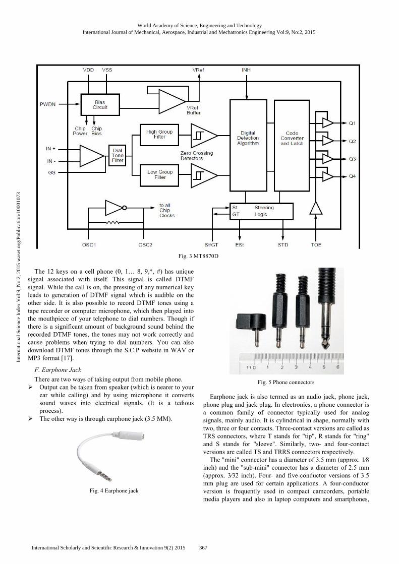
Fig. 3 MT8870D
The 12 keys on a cell phone (0, 1… 8, 9,*, #) has unique
signal associated with itself. This signal is called DTMF
signal. While the call is on, the pressing of any numerical key
leads to generation of DTMF signal which is audible on the
other side. It is also possible to record DTMF tones using a
tape recorder or computer microphone, which then played into
the mouthpiece of your telephone to dial numbers. Though if
there is a significant amount of background sound behind the
recorded DTMF tones, the tones may not work correctly and
cause problems when trying to dial numbers. You can also
download DTMF tones through the S.C.P website in WAV or
MP3 format [17].
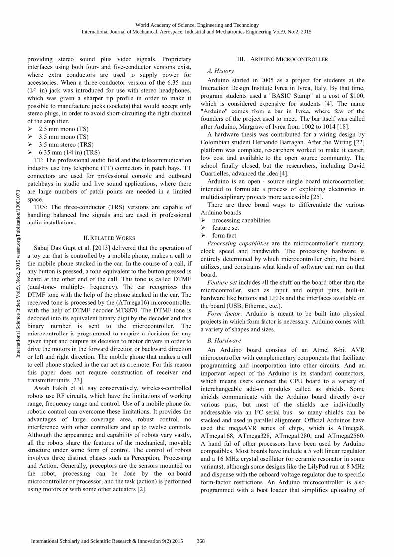
F. Earphone Jack
There are two ways of taking output from mobile phone.
� Output can be taken from speaker (which is nearer to your
ear while calling) and by using microphone it converts
sound waves into electrical signals. (It is a tedious
process).
� The other way is through earphone jack (3.5 MM).
Fig. 4 Earphone jack
Fig. 5 Phone connectors
Earphone jack is also termed as an audio jack, phone jack,
phone plug and jack plug. In electronics, a phone connector is
a common family of connector typically used for analog
signals, mainly audio. It is cylindrical in shape, normally with
two, three or four contacts. Three-contact versions are called as
TRS connectors, where T stands for "tip", R stands for "ring"
and S stands for "sleeve". Similarly, two- and four-contact
versions are called TS and TRRS connectors respectively.
The "mini" connector has a diameter of 3.5 mm (approx. 1⁄8
inch) and the "sub-mini" connector has a diameter of 2.5 mm
(approx. 3⁄32 inch). Four- and five-conductor versions of 3.5
mm plug are used for certain applications. A four-conductor
version is frequently used in compact camcorders, portable
media players and also in laptop computers and smartphones,
World Academy of Science, Engineering and TechnologyInternational Journal of Mechanical, Aerospace, Industrial and Mechatronics Engineering Vol:9, No:2, 2015
367International Scholarly and Scientific Research & Innovation 9(2) 2015
Inte
rnat
iona
l Sci
ence
Ind
ex V
ol:9
, No:
2, 2
015
was
et.o
rg/P
ublic
atio
n/10
0010
73
providing stereo sound plus video signals. Proprietary
interfaces using both four- and five-conductor versions exist,
where extra conductors are used to supply power for
accessories. When a three-conductor version of the 6.35 mm
(1⁄4 in) jack was introduced for use with stereo headphones,
which was given a sharper tip profile in order to make it
possible to manufacture jacks (sockets) that would accept only
stereo plugs, in order to avoid short-circuiting the right channel
of the amplifier.
� 2.5 mm mono (TS)
� 3.5 mm mono (TS)
� 3.5 mm stereo (TRS)
� 6.35 mm (1⁄4 in) (TRS)
TT: The professional audio field and the telecommunication
industry use tiny telephone (TT) connectors in patch bays. TT
connectors are used for professional console and outboard
patchbays in studio and live sound applications, where there
are large numbers of patch points are needed in a limited
space.
TRS: The three-conductor (TRS) versions are capable of
handling balanced line signals and are used in professional
audio installations.
II. RELATED WORKS
Sabuj Das Gupt et al. [2013] delivered that the operation of
a toy car that is controlled by a mobile phone, makes a call to
the mobile phone stacked in the car. In the course of a call, if
any button is pressed, a tone equivalent to the button pressed is
heard at the other end of the call. This tone is called DTMF
(dual-tone- multiple- frequency). The car recognizes this
DTMF tone with the help of the phone stacked in the car. The
received tone is processed by the (ATmega16) microcontroller
with the help of DTMF decoder MT8870. The DTMF tone is
decoded into its equivalent binary digit by the decoder and this
binary number is sent to the microcontroller. The
microcontroller is programmed to acquire a decision for any
given input and outputs its decision to motor drivers in order to
drive the motors in the forward direction or backward direction
or left and right direction. The mobile phone that makes a call
to cell phone stacked in the car act as a remote. For this reason
this paper does not require construction of receiver and
transmitter units [23].
Awab Fakih et al. say conservatively, wireless-controlled
robots use RF circuits, which have the limitations of working
range, frequency range and control. Use of a mobile phone for
robotic control can overcome these limitations. It provides the
advantages of large coverage area, robust control, no
interference with other controllers and up to twelve controls.
Although the appearance and capability of robots vary vastly,
all the robots share the features of the mechanical, movable
structure under some form of control. The control of robots
involves three distinct phases such as Perception, Processing
and Action. Generally, preceptors are the sensors mounted on
the robot, processing can be done by the on-board
microcontroller or processor, and the task (action) is performed
using motors or with some other actuators [2].
III. ARDUINO MICROCONTROLLER
A. History
Arduino started in 2005 as a project for students at the
Interaction Design Institute Ivrea in Ivrea, Italy. By that time,
program students used a "BASIC Stamp" at a cost of $100,
which is considered expensive for students [4]. The name
"Arduino" comes from a bar in Ivrea, where few of the
founders of the project used to meet. The bar itself was called
after Arduino, Margrave of Ivrea from 1002 to 1014 [18].
A hardware thesis was contributed for a wiring design by
Colombian student Hernando Barragan. After the Wiring [22]
platform was complete, researchers worked to make it easier,
low cost and available to the open source community. The
school finally closed, but the researchers, including David
Cuartielles, advanced the idea [4].
Arduino is an open - source single board microcontroller,
intended to formulate a process of exploiting electronics in
multidisciplinary projects more accessible [25].
There are three broad ways to differentiate the various
Arduino boards.
� processing capabilities
� feature set
� form fact
Processing capabilities are the microcontroller’s memory,
clock speed and bandwidth. The processing hardware is
entirely determined by which microcontroller chip, the board
utilizes, and constrains what kinds of software can run on that
board.
Feature set includes all the stuff on the board other than the
microcontroller, such as input and output pins, built-in
hardware like buttons and LEDs and the interfaces available on
the board (USB, Ethernet, etc.).
Form factor: Arduino is meant to be built into physical
projects in which form factor is necessary. Arduino comes with
a variety of shapes and sizes.
B. Hardware
An Arduino board consists of an Atmel 8-bit AVR
microcontroller with complementary components that facilitate
programming and incorporation into other circuits. And an
important aspect of the Arduino is its standard connectors,
which means users connect the CPU board to a variety of
interchangeable add-on modules called as shields. Some
shields communicate with the Arduino board directly over
various pins, but most of the shields are individually
addressable via an I²C serial bus—so many shields can be
stacked and used in parallel alignment. Official Arduinos have
used the megaAVR series of chips, which is ATmega8,
ATmega168, ATmega328, ATmega1280, and ATmega2560.
A hand ful of other processors have been used by Arduino
compatibles. Most boards have include a 5 volt linear regulator
and a 16 MHz crystal oscillator (or ceramic resonator in some
variants), although some designs like the LilyPad run at 8 MHz
and dispense with the onboard voltage regulator due to specific
form-factor restrictions. An Arduino microcontroller is also
programmed with a boot loader that simplifies uploading of
World Academy of Science, Engineering and TechnologyInternational Journal of Mechanical, Aerospace, Industrial and Mechatronics Engineering Vol:9, No:2, 2015
368International Scholarly and Scientific Research & Innovation 9(2) 2015
Inte
rnat
iona
l Sci
ence
Ind
ex V
ol:9
, No:
2, 2
015
was
et.o
rg/P
ublic
atio
n/10
0010
73
programs to the on-chip flash memory and compared with
other devices that typically need an external programmer,
which makes using an Arduino more straightforward by
allowing the use of an ordinary computer as the programmer.
At a conceptual level, when using the Arduino software
stack, all boards are programmed through an RS-232 serial
connection, but the way which is implemented varies by
hardware version. Serial Arduino boards contain a special
circuit called level shifter circuit to convert between RS-232-
level and TTL-level signals. The ongoing Arduino boards are
programmed through USB, implemented using USB-to-serial
adapter chips such as the FTDI FT232. Some alternatives such
as the Arduino Mini and the unofficial Arduino, use a
detachable USB-to-serial adapter board or cables, Bluetooth or
other methods. (When used with traditional microcontroller
tools instead of the Arduino IDE, standard AVR ISP program
is used.)
The Arduino board exposes most of the microcontroller's
I/O pins for use by variant circuits. The Diecimila,
Duemilanove, and current Uno provide 14 digital I/O pins, six
of fourteen which can produce pulse-width modulated signals,
and six analog inputs, this can also be used as six digital I/O
pins. These pins are on the top of the board, via female 0.10-
inch (2.5 mm) headers. Several plug-in applications shields are
also commercially obtainable. The Arduino Nano, and
Arduino-compatible Bare Bones Board and Arduino boards
may provide male header pins on the underside of the board
that can plug into solderless breadboards.
There are many Arduino-compatible and Arduino-derived
boards. In which some are functionally equivalent to an
Arduino and can be used vice versa. Many enhance the basic
Arduino by adding output drivers, often used in school-level
education to simplify the construction of buggies and small-
scale robots. Others are electrically equivalent but change the
form factor—sometimes retaining compatibility with shields,
sometimes not. Some revision use completely different
processors, with varying levels of similarity.
C. Software
The Arduino integrated development environment (IDE) is a
cross-platform application written in Java and which is
obtained from the IDE for the Processing programming
language and the Wiring projects. It is sketched to introduce
programming to artists and other newcomers unfamiliar with
software development. It comprises a code editor with features
such as syntax spotlighted, brace matching, and automated
indentation and is also capable of compiling and uploading
programs to the board with a single click. A program or codes
written for Arduino is called a sketch [21].
The Arduino programs are written in C or C++. An Arduino
IDE comes with a software library called "Wiring" from the
original Wiring projects, which makes many common
input/output operations much simple. Users only need to
define two functions to make a runnable cyclic executive
program:
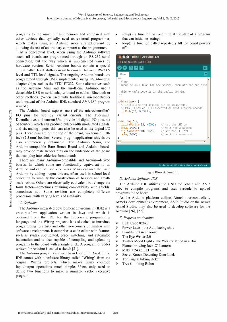
• setup(): a function run one time at the start of a program
that can initialize settings
• loop(): a function called repeatedly till the board powers
off
Fig. 6 Blink|Arduino 1.0
D. Arduino Software IDE
The Arduino IDE utilizes the GNU tool chain and AVR
Libc to compile programs and uses avrdude to upload
programs to the board.
As the Arduino platform utilizes Atmel microcontrollers,
Atmel's development environment, AVR Studio or the newer
Atmel Studio, may also be used to develop software for the
Arduino [26], [27].
E. Projects on Arduino
� LED Cube 8x8x8
� Power Laces- the Auto lacing shoe
� Plantduino Greenhouse
� The Eye Writer 2.0
� Twitter Mood Light - The World's Mood in a Box
� Flame throwing Jack-O'-Lantern
� Make a 24X6 LED matrix
� Secret Knock Detecting Door Lock
� Turn signal biking jacket
� Tree Climbing Robot
World Academy of Science, Engineering and TechnologyInternational Journal of Mechanical, Aerospace, Industrial and Mechatronics Engineering Vol:9, No:2, 2015
369International Scholarly and Scientific Research & Innovation 9(2) 2015
Inte
rnat
iona
l Sci
ence
Ind
ex V
ol:9
, No:
2, 2
015
was
et.o
rg/P
ublic
atio
n/10
0010
73
S.No Name Pictorial Representation
01 ARDUINO UNO
02 ARDUINO LEONARDO
03 ARDUINO DUE
04 ARDUINO MICRO
05 LILYPAD ARDUINO
06 ARDUINO ESPLORA
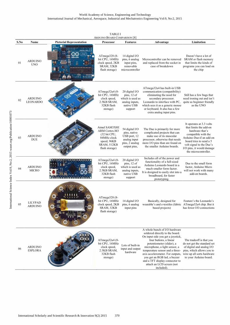
TABLE I ARDUINO BOARD COMPARISON [8]
Pictorial Representation Processor Features Advantage
ATmega328 (8-bit CPU, 16MHz clock speed, 2KB SRAM, 32KB flash storage)
14 digital I/O pins, 6 analog input pins, removable
microcontroller
Microcontroller can be removed and replaced from the socket in
case of breakdown
ATmega32u4 (8-bit CPU, 16MHz clock speed, 2.5KB SRAM, 32KB flash storage)
20 digital I/O pins, 12 of
which is used as analog inputs, native USB support
ATmega32u4 has builtcommunication (compatibility) eliminating the need for secondary pr
Leonardo to interface with PC, which sees it as a generic mouse or keyboard. It also has a few extra analog input pins.
Atmel SAM3X8E ARM Cortex-M3 (32 bit CPU, 84MHz clock speed, 96KB SRAM, 512KB flash storage)
54 digital I/O pins, native USB port, 12 analog input pins, 2 analog output pins,
The Due is primarily for more complicated projects that can make use of its muscular
processor, otherwise that needs more I/O pins than are found on the smaller Arduino boards.
ATmega32u4 (8-bit CPU, 16MHz clock speed, 2.5KB SRAM, 32KB flash storage)
20 digital I/O pins, 12 of
which is used as analog inputs, native USB support
Includes all of the power and functionality of a fullArduino Leonardo board in a much smaller form factor.
It is designed to easily slot into a breadboard, for faster
prototyping.
ATmega328 (8-bit CPU, 16MHz clock speed, 2KB SRAM, 32KB flash storage)
14 digital I/O pins, 6 analog input pins
Basically, designed for wearable’s and e
based projects)
ATmega32u4 (8-bit CPU, 16MHz clock speed, 2.5KB SRAM, 32KB flash storage)
Lots of built-in input and output hardware
A whole bunch of I/O hardware soldered directly to the board. On input side you get a joystick,
four buttons, a linear potentiometer (slider), a
microphone, a light sensor, a temperature sensor and a threeaxis accelerometer. For outputs, you get an RGB led, a buzzer and a TFT display connector to attach an LCD screen (not
included).
Advantage Limitation
Microcontroller can be removed and replaced from the socket in
breakdown
Doesn’t have a lot of SRAM or flash memory that limits the kinds of programs you can load on
the chip
ATmega32u4 has built-in USB communication (compatibility) eliminating the need for secondary processor.
Leonardo to interface with PC, which sees it as a generic mouse or keyboard. It also has a few extra analog input pins.
Still has a few bugs that need ironing out and isn’t quite as beginner friendly
as the UNO
The Due is primarily for more complicated projects that can make use of its muscular
erwise that needs more I/O pins than are found on the smaller Arduino boards.
It operates at 3.3 volts that limits the add-on hardware that’s
compatible with the Arduino Due-if an add-on board tries to send a 5 volt signal to the Due’s I/O pins, it would damage the microcontroller.
Includes all of the power and functionality of a full-sized Arduino Leonardo board in a much smaller form factor.
It is designed to easily slot into a breadboard, for faster
prototyping.
Due to the small form factor, Arduino Micro will not work with many
add-on boards.
designed for wearable’s and e-textiles (fabric
based projects)
Feature’s the Leonardo’s ATmega32u4 chip. But it has fewer I/O connections
A whole bunch of I/O hardware soldered directly to the board. On input side you get a joystick,
four buttons, a linear er (slider), a
microphone, a light sensor, a temperature sensor and a three-axis accelerometer. For outputs, you get an RGB led, a buzzer and a TFT display connector to attach an LCD screen (not
included).
The tradeoff is that you do not get the standard set of digital and analog I/O pins, which allows you to wire up all sorts hardware to your Arduino board.
World Academy of Science, Engineering and TechnologyInternational Journal of Mechanical, Aerospace, Industrial and Mechatronics Engineering Vol:9, No:2, 2015
370International Scholarly and Scientific Research & Innovation 9(2) 2015
Inte
rnat
iona
l Sci
ence
Ind
ex V
ol:9
, No:
2, 2
015
was
et.o
rg/P
ublic
atio
n/10
0010
73
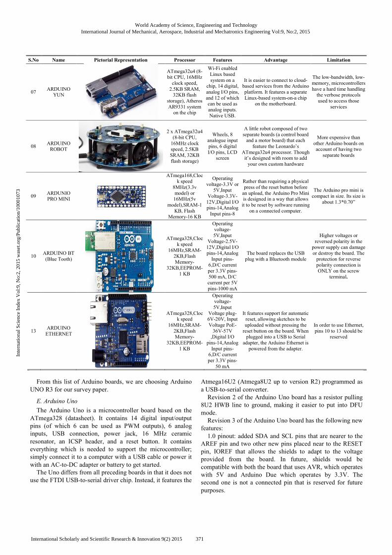
S.No Name Pictorial Representation Processor Features Advantage Limitation
07 ARDUINO YUN
ATmega32u4 (8-bit CPU, 16MHz clock speed, 2.5KB SRAM, 32KB flash
storage), Atheros AR9331 system on the chip
Wi-Fi enabled Linux based system on a
chip, 14 digital, analog I/O pins, and 12 of which can be used as analog inputs. Native USB.
It is easier to connect to cloud-based services from the Arduino platform. It features a separate Linux-based system-on-a chip
on the motherboard.
The low-bandwidth, low-memory, microcontrollers have a hard time handling the verbose protocols used to access those
services
08 ARDUINO ROBOT
2 x ATmega32u4 (8-bit CPU, 16MHz clock speed, 2.5KB SRAM, 32KB flash storage)
Wheels, 8 analogue input pins, 6 digital I/O pins, LCD
screen
A little robot composed of two separate boards (a control board and a motor board) that each feature the Leonardo’s
ATmega32u4 processor. Though it’s designed with room to add your own custom hardware
More expensive than other Arduino boards on account of having two separate boards
09 ARDUNIO PRO MINI
ATmega168,Clock speed
8MHz(3.3v model) or 16MHz(5v
model),SRAM-1 KB, Flash
Memory-16 KB
Operating voltage-3.3V or 5V,Input
Voltage-3.3V-12V,Digital I/O pins-14,Analog Input pins-8
Rather than requiring a physical press of the reset button before an upload, the Arduino Pro Mini is designed in a way that allows it to be reset by software running
on a connected computer.
The Arduino pro mini is compact in size. Its size is
about 1.3*0.70”
10 ARDUINO BT (Blue Tooth)
ATmega328,Clock speed
16MHz,SRAM-2KB,Flash Memory-
32KB,EEPROM-1 KB
Operating voltage- 5V,Input
Voltage-2.5V-12V,Digital I/O pins-14,Analog Input pins-6,D/C current per 3.3V pins-500 mA, D/C current per 5V pins-1000 mA
The board replaces the USB plug with a Bluetooth module
Higher voltages or reversed polarity in the power supply can damage or destroy the board. The protection for reverse polarity connection is ONLY on the screw
terminal.
13 ARDUINO ETHERNET
ATmega328,Clock speed
16MHz,SRAM-2KB,Flash Memory-
32KB,EEPROM-1 KB
Operating voltage- 5V,Input
Voltage plug-6V-20V, Input Voltage PoE-36V-57V ,Digital I/O
pins-14,Analog Input pins-6,D/C current per 3.3V pins-
50 mA
It features support for automatic reset, allowing sketches to be uploaded without pressing the reset button on the board. When plugged into a USB to Serial adapter, the Arduino Ethernet is powered from the adapter.
In order to use Ethernet, pins 10 to 13 should be
reserved
From this list of Arduino boards, we are choosing Arduino
UNO R3 for our survey paper.
E. Arduino Uno
The Arduino Uno is a microcontroller board based on the
ATmega328 (datasheet). It contains 14 digital input/output
pins (of which 6 can be used as PWM outputs), 6 analog
inputs, USB connection, power jack, 16 MHz ceramic
resonator, an ICSP header, and a reset button. It contains
everything which is needed to support the microcontroller;
simply connect it to a computer with a USB cable or power it
with an AC-to-DC adapter or battery to get started.
The Uno differs from all preceding boards in that it does not
use the FTDI USB-to-serial driver chip. Instead, it features the
Atmega16U2 (Atmega8U2 up to version R2) programmed as
a USB-to-serial converter.
Revision 2 of the Arduino Uno board has a resistor pulling
8U2 HWB line to ground, making it easier to put into DFU
mode.
Revision 3 of the Arduino Uno board has the following new
features:
1.0 pinout: added SDA and SCL pins that are nearer to the
AREF pin and two other new pins placed near to the RESET
pin, IOREF that allows the shields to adapt to the voltage
provided from the board. In future, shields would be
compatible with both the board that uses AVR, which operates
with 5V and Arduino Due which operates by 3.3V. The
second one is not a connected pin that is reserved for future
purposes.
World Academy of Science, Engineering and TechnologyInternational Journal of Mechanical, Aerospace, Industrial and Mechatronics Engineering Vol:9, No:2, 2015
371International Scholarly and Scientific Research & Innovation 9(2) 2015
Inte
rnat
iona
l Sci
ence
Ind
ex V
ol:9
, No:
2, 2
015
was
et.o
rg/P
ublic
atio
n/10
0010
73
� Stronger RESET circuit.
� Atmega 16U2 replace the 8U2.
� Processor: ATmega328 (8-bit CPU, 16MHz clock speed,
32KB flash storage, 2KB SRAM)
� Features: 6 analog input pins, 14 digital I/O pins,
removable microcontroller
� Form Factor: 2.7” * 2.1” rectangle
� Price: $30 [7].
The Arduino Uno is the most “standard” Arduino board
currently in the market, and is probably the best choice for
beginners just getting started with the platform. The board is
well-suited with more shields (add-on boards) than other
models.
Arduino simplifies the process of working with
microcontrollers, and offers some advantages for students,
teachers and interested amateurs over other systems:
� Cross-platform - The Arduino software runs on Macintosh
OSX, Windows and Linux operating systems. Most of the
microcontroller systems are limited to Windows.
� Simple, clear programming environment - The Arduino
programming environment is easy-to-use for the
beginners, yet flexible enough for the advanced users. For
teachers, it is conveniently based on the Processing
programming environment, hence students are learning to
program in that environment will be familiar with the look
and feel of Arduino
� Open source and extensible software - The Arduino
software is published as open source tools, available for
extension by the experienced programmers. The language
can be expanded through the C++ libraries, and people
wanting to understand the technical details can make the
leap from Arduino to the AVR C programming language
on which it is based. Likewise, you have the capacity to
add AVR-C code directly into your Arduino programs if
you want to.
� Open source and extensible hardware - The Arduino is
based on Atmel's ATMEGA8 and ATMEGA168
microcontrollers. The plans for modules are published
under a Creative Commons license, hence experienced
circuit designers can create their own version of the
module, which can be extended and improved. Even
relatively inexperienced users can build the breadboard
version of the module in order to understand how it works
and save money.
The Uno's main limitation is ATmega328 chip, which
doesn’t have lot of SRAM or flash memory, which limits the
kinds of programs you can load on the chip—if your project
involves a display or otherwise needs to store and use any
form of images or audio data, 2KB of memory isn’t going to
be enough [7].
Features of ATmega328P Microcontroller (used by the
Arduino):
� AVR 8-bit RISC architecture
� Available in DIP package
� Up to 20 MHz clock
� 32kB flash memory
� 1 kB SRAM
� 23 programmable I/O channels
� Six 10-bit ADC inputs
� Three timers/counters
� Six PWM outputs [16].
Bare Minimum:
The bare minimum of code is needed to start an Arduino
sketch.
Hardware Required:
� Arduino Board
Code: void setup () {
// put your setup code here, to run once:
}
void loop () {
// put your main code here, to run repeatedly:
} [10].
Blink:
Turn an LED on and off.
Hardware Required:
� Arduino Board
� LED
� Resistor, anything between 220 ohm to 1K ohm
Code:
/*
Turns on LED on for one second, then off for one second,
repeatedly.
*/
// Pin 13 has a LED connected on most of the Arduino boards.
// give it a name:
int led = 13;
// the setup routine runs once when you press the reset:
void setup () {
// initialize the digital pin as a output.
pinMode (led, OUTPUT);
}
void loop ()
{
digitalWrite (led, HIGH); // turn the LED on (HIGH is the
voltage level)
delay (1000); // wait for a second
digitalWrite(led, LOW); // turn the LED off by making the
voltage LOW
delay (1000); // wait for a second
} [11].
Digital Read Serial:
It reads the switch, print the state out to the Arduino Serial
Monitor.
Hardware Required
� Arduino Board
� A momentary switch, button, or toggle switch
� 10k ohm resistor
� breadboard
� hook-up wire
World Academy of Science, Engineering and TechnologyInternational Journal of Mechanical, Aerospace, Industrial and Mechatronics Engineering Vol:9, No:2, 2015
372International Scholarly and Scientific Research & Innovation 9(2) 2015
Inte
rnat
iona
l Sci
ence
Ind
ex V
ol:9
, No:
2, 2
015
was
et.o
rg/P
ublic
atio
n/10
0010
73
Code:
/*
DigitalReadSerial
Reads a digital input on pin 2, prints the result to the serial monitor
*/
// digital pin 2 has a pushbutton attached towards it. Give it a
name:
int pushButton = 2;
// the setup routine runs once when you press the reset:
void setup ()
{
// initialize serial communication by 9600 bits per second:
Serial.begin(9600);
// make the pushbutton's pin an input:
pinMode(pushButton, INPUT);
}
void loop ()
{
// read the input pin:
int buttonState = digitalRead(pushButton);
// print out the state of the button:
Serial.println(buttonState);
delay (1);
// delay in between reads for stability
} [12].
Analog Read Serial:
It reads the potentiometer, print its state out to the Arduino
Serial Monitor.
Hardware Required:
� Arduino Board
� 10-kilohm Potentiometer
Code:
/*
AnalogReadSerial
Reads the analog input on pin 0, prints the result to the serial
monitor.
Attach the center pin of the potentiometer to pin A0, and the
outside pins to +5V and ground.
*/
// the setup routine runs once when you press the reset:
void setup ()
{
// initialize serial communication by 9600 bits per second:
Serial.begin(9600);
}
void loop ()
{
// read the input on analog pin 0:
int sensorValue = analogRead(A0);
// print out the value you read:
Serial.println(sensorValue);
delay (1);
// delay in between reads for stability
} [9].
Fade:
Following code demonstrates the process of analog signals
output to fade an LED.
Hardware Required
� Arduino board
� Breadboard
� a LED
� a 220 ohm resistor
Code:
/*
Fade
This example shows how to fade an LED on pin 9
using the analogWrite() function.
*/
int led = 9; // the pin that the LED is attached to
int brightness = 0; // how bright the LED is
int fadeAmount = 5; // how many points to fade the LED by
// the setup routine runs once when you press reset:
void setup ()
{
// declare pin 9 to be an output:
pinMode (led, OUTPUT);
}
// the loop routine runs over and over again forever:
void loop ()
{
// set the brightness of pin 9:
analogWrite (led, brightness);
// change the brightness for next time through the loop:
brightness = brightness + fadeAmount;
// reverse the direction of the fading at the ends of the fade:
if (brightness == 0 || brightness == 255)
{
fadeAmount = -fadeAmount ;
}
// wait for 30 milliseconds to see the dimming effect
delay (30);
} [13].
Read Analog Voltage:
It reads an analog input and prints the voltage to the serial
monitor.
Hardware Required
� Arduino Board
� a variable resistor, like a potentiometer
Code:
/*
ReadAnalogVoltage
Reads an analog input on pin 0, converts it to voltage, and prints
the result to the serial monitor.
Attach the center pin of a potentiometer to pin A0, and the outside
pins to +5V and ground.
*/
// the setup routine runs once when you press reset:
void setup ()
{
// initialize serial communication at 9600 bits per second:
Serial.begin(9600);
}
// the loop routine runs over and over again forever:
void loop ()
{
World Academy of Science, Engineering and TechnologyInternational Journal of Mechanical, Aerospace, Industrial and Mechatronics Engineering Vol:9, No:2, 2015
373International Scholarly and Scientific Research & Innovation 9(2) 2015
Inte
rnat
iona
l Sci
ence
Ind
ex V
ol:9
, No:
2, 2
015
was
et.o
rg/P
ublic
atio
n/10
0010
73
// read the input on analog pin 0:
int sensorValue = analogRead(A0);
// Convert the analog reading (which goes from 0 - 1023) to a
voltage (0 - 5V):
float voltage = sensorValue * (5.0 / 1023.0);
// print out the value you read:
Serial.println(voltage);} [14].
IV. CONCLUSION
In this paper we have reviewed various types of
controllers. The advantages of using different Arduino board
are: Arduino Uno-easily replaceable, Arduino Leonardo-
eliminates the need of secondary processor and Arduino Due-
used in complicated project. Arduino micro –enables faster
prototyping, Lily pad Arduino – wearable’s and e-textiles,
Arduino Esplora- has joysticks, microphone, sensors on input
side and buzzer on output side, Arduino yun-support cloud
based services, Arduino Robot-support our own customed
hardware parts. This study provides a wide description about
Arduino processor; it will be helpful for many robotic
researchers.
REFERENCES
[1] A Guide to Understanding and Exploiting Australia’s Most Common Telecommunications Signaling Method.
[2] Awab Fakih, Jovita Serrao, Cell Phone Operated Robotic Car. International Journal of Scientific & Engineering Research, ISSN 2229-5518.
[3] Amritanshu Srivastava, Hrishikesh Narayan Tripathi, GSM Calling based Multi-tasking Robot vehicle with Password protection International Journal of Advanced Research in Computer Science and Software Engineering, ISSN: 2277 128X.
[4] David Kushner (26 Oct 2011). "The Making of Arduino". IEEE Spectrum.
[5] Edwin Wise, Robotics Demystified (Mc-Graw Hill, 2005). [6] Hector of SCP, Dual Tone Multiple Frequency A guide to understanding
and exploiting Australians most common telecommunications signaling method. December 10th 2003.
[7] http://arduino.cc/en/main/arduinoBoardUno. [8] http://arduino.cc/en/Products.Compare. [9] http://arduino.cc/en/Tutorial/AnalogReadSerial. [10] http://arduino.cc/en/Tutorial/BareMinimum. [11] http://arduino.cc/en/Tutorial/Blink. [12] http://arduino.cc/en/Tutorial/DigitalReadSerial. [13] http://arduino.cc/en/Tutorial/Fade. [14] http://arduino.cc/en/Tutorial/ReadAnalogVoltage. [15] http://www.allonrobots.com/types-of-robots.html. [16] http://www.handsonresearch.org/2012/PDF/IntroductionToArduino.pdf [17] http://www.microsemi.com/products/telephony/dtmf-receivers/mt8870d. [18] Justin Lahart (27 November 2009). "Taking an Open-Source Approach
to Hardware". The Wall Street Journal. Retrieved 7 September 2014. [19] L. Schenker, "Pushbutton Calling with a Two-Group Voice-Frequency
Code", The Bell System Technical Journal, 39(1), 1960, 235–255, ISSN 0005-8580.
[20] Mobile Operated Landrover Using Dtmf Decoder, International Journal of Modern Engineering Research (IJMER) Vol.3, Issue.2, March-April. 2013 pp-898-902 ISSN: 2249-6645.
[21] "Programming Arduino Getting Started with Sketches". McGraw-Hill. Nov 8, 2011. Retrieved 2013-03-28.
[22] "Rhizome - Interview with Casey Reas and Ben Fry". 2009-09-23. Retrieved 2014-08-23.
[23] Sabuj Das Gupta et al (2013) “Designing and implementation of Mobile operated toy car by DTMF” international journal of scientific research and Publication, ISSN 2250-3153.
[24] Sumona Biswas, Bipin Kumar, Aditya kushwaha, Debasish Sardar, Cell Phone Operated Land Rover, International Journal on Recent and Innovation Trends in Computing and Communication ISSN: 2321-8169 Volume: 2 Issue: 3 617 – 621.
[25] T.K. Sethuramalingam and M. Karthighairasan, Automatic Gas Valve Control System using Arduino Hardware, Bonfring International Journal of Power Systems and Integrated Circuits, Vol. 2, No. 3, September 2012.
[26] "Using Atmel Studio for Arduino development". Megunolink.com. Retrieved 2013-01-18.
[27] "Using AVR Studio for Arduino development". Engblaze.com. Retrieved 2013-01-18.
Mr. C. Rajan received his B.E Degree in Computer Science and engineering from SSN College of engineering at University of Madras. Then he obtained his Master’s degree in Computer Science. He is pursuing Ph.D. at Anna University of Technology, Coimbatore. He is currently working as an Assistant Professor in the Department of Information Technology, KSR College of Technology. He has 10 years of teaching experience. He has presented 11 papers in various national and international journals. His research interests Multicasting Networks, Key Management and Network Security. Miss. B. Megala is a B.Tech student of Information Technology department in K. S. Rangasamy College of Technology. She has presented five papers in National level technical symposium. She is an active member of ISTE. Her Research interests include Robotics, Cloud Computing and Ad hoc Networks. Miss. A. Nandhini is a B.Tech student of Information Technology department in K. S. Rangasamy College of Technology. She has presented three papers in National level technical symposium. She is an active member of ISTE. Her Research interests include Robotics and Mobile Computing. Miss. C. Rasi Priya holds a B.Tech degree in Information Technology from K. S. Rangasamy College of technology, affiliated to Anna University of Technology Coimbatore, Tamil Nadu, India in 2013. Now she is an M.Tech student of Information Technology department in K. S. Rangasamy College of Technology. She has published 3 international journals and presented two papers in National level Conferences. She is an active member of ISTE. Her Research interests include Mobile computing, Ad hoc Networks and Security.
World Academy of Science, Engineering and TechnologyInternational Journal of Mechanical, Aerospace, Industrial and Mechatronics Engineering Vol:9, No:2, 2015
374International Scholarly and Scientific Research & Innovation 9(2) 2015
Inte
rnat
iona
l Sci
ence
Ind
ex V
ol:9
, No:
2, 2
015
was
et.o
rg/P
ublic
atio
n/10
0010
73
Related Documents


![GESTURE REGULATED ANIMATRONIC ROBOTIC HAND · using MATLAB to control Arduino based Robotic Arm. International conference on pervasive computing, 2015. [5] Panth Shah, Tithi Vyas.](https://static.cupdf.com/doc/110x72/5f01b9307e708231d400ba77/gesture-regulated-animatronic-robotic-hand-using-matlab-to-control-arduino-based.jpg)