. • NASA-TM-80280 19790014003 A Reproduced Copy OF .llli 1 ? ;1M\ Reproduced for NASA by the NAS A Scientific and Technical Information Facility FFNo 67 2 Au g 65

Welcome message from author
This document is posted to help you gain knowledge. Please leave a comment to let me know what you think about it! Share it to your friends and learn new things together.
Transcript
. •
NASA-TM-80280 197900 14003
A Reproduced Copy OF
.llli 1 ? ;1M\
Reproduced for NASA
by the
NASA Scientific and Technical Information Facility
FFNo 672 Aug 65
.'
_. __ .............. - - - .... --- --"'-- "'- ._ ..... _----,-----3 1176 01324 9397
Techn"cal e orand m 802 0 (NhSA - T - 80280 ) S Y NCHR0 1~OOS OBBIT l'OtlER N79-22 174 TEC HNOLOGY NE EDS ( ~AS A ) 36 P HC A03/ MF AOl
l . Hf r, Jr. and
APRil 1979
National Aeronautics and Space Administration
Goddard Space Flig Greenbelt, Maryland 20771
csc!. 22A One l a s
G3/12 2535q
r
'"'\. - .
\
. ::\
\ . . . ~ .
TM 80280
"
SY NCHRONOUS ORBIT POWER TECHNOLOGY NEEDS
Luther w. Slifer, Jr.
NASA/Goddard Space Flight Center
Wilfred J. BiIlerbeck
COMSA T Laboratories
;.
April 1979
GODDARD SPACE FLIGHT CENTER
Greenbelt . M ry land 2077 1
-'
SYNCHRONOUS ORBIT POWER TECHNOLOGY NEEDSi·
Luther W. Slifer, Jr.·
NASA/Goddard Space Flight Center
Wilfred J. Billerbecku
COMSAT Laboratories
ABSTRACf
The objective of this paper is to define the needs for future geosynchronous orbit spacecraft
power subsystem components, including power generation, energy storage, and power processing.
A review of the rapid expansion of the 5ate!lite communications field provid s a basis for projection
into the future. Three projecterl models, a mission model, an orbit transfer vehicle model, and a
mass.rnodel for power subsystem components are used to define power requirements and mass limi-
tations for future spacecraft. Based upon these three models, the power subsystems for a IOkw, 10
yeiiT life, d dicated spacecraft an for n 20 kw, 20 year life, I •• I i-mission JJtform are analyzed iii
further detail to establish power densit~' requirements for the generation, storage and processing
components of power subsystems as related to orbit transfer vehicle capabilities. Comparison of
these reqtillements to state of the art (INTELSAT-V) design values shows that major improvements,
by a factor of 2 or more, are needed to accomplish the near term missi~ s. However, with the advent
of large transfer vehldes, these requirements are ignifican tly reduced , leaving the long lifetime re-
quirement, associated with reliability and/or refurbishment, as the primary development need. A
few technology advances, currently under development, are noted with regard to their impacts on
future capability.
tThis work was supporled by COM SAT La borator ';s (I NTELSAT) and NASA/Goddard Space Flighl Center. ·Staff Engineer, Space Power Applica tions Branch
--Manager. Electric Power [)ePll! ment
iii
S·LAN·' t f(. T rll_Ml.. o r--cr.E.. 1~4G ?AGE t "I:. ~
_ .... _ - 1* J
J
CONTEN'PJ
Page
PRECEDl G PAGE BLANK NOT J. l " ' t - ... ABSTRACT ... ... . . ..... . ... . ... . ..... ... ... .. .. . ...... .. .. .. .......... .... . ... ill
.'
INTRODUCfION . . ..... ... ........ .. ... .. .. ... ...... . .. . ........... . ... .... .. .. 1
GROWTH IN COMMUNICATIONS TECHNOLOGY ......... . ........................ . . 1
Growth in Power Requirements ...... . . . . .... ... . . ..... ... .. ... ................ 4
PROJECTED MODELS ... . ... ....... ... . . . ........... ... ...... . ..... . ..... .... .. 6
Mission Model . . ..... . .. ............. . .. ... . .. .. . .. ... . ............. . ....... 7
Orbit Transfer Vehicle Model ..... . ........ .. . . . . ..... . ..................... . .. 8
Mass Model for Power Subsystem Components .......................... .. . . . .... . 10
REFERENCE SPACECRAFT AND PLATFORM .. . ... . ... . . . ............ . . . . .. ... . .. 11
Reference Dedicated Spacecraft (1985 Time Frame) ... . ............ . ....... .. . ... . 11
Reference Multi-Mission Platfonn (1985-1990 Time Framr.) . .. . . ... .... . . ..... ...... 13
Power Density Requirements ....... .. .. ... ... ............... .. .... .. ........ . 14
Lifetime Requirements .... .. . .. ...... .... . .... ......... .. . .. ... . ........... . 14
Additional Requirements ... .................. . .............. ..... ......... .. 14
FUTURE:. ADVANCES IN TE:::HNOLOGY . . .... " ., ... . .... ' " ... .. . ... . ........... 16
Solar Energy Conversion ........ .. . .. ..... .. . ..... . . . . ....... . .......... . .. . . 16
Energy Storage ........................................ . ...... .... ........ . 20
CONCLUSIONS ... . ............... . . .. . ..... . .. . . ........ . ........ . .. . .. ...... 28
ACKNOWLEDGM ENT ..... ..... ..... . ....... . ... ...... .... . .. . ... .... ....... . .. 29
REF~RENCES ...... . .. . ...... . ... ....... . ..... . . . . . ... .... ...... ....... ..... . 29
v
------ ----.
ILLUSTRA nONS
Figure Page
-' Earth Stations in the INTELSA T System ...... ... ... .. .. .. ... ...... . ...... . ... . 2
2 Full-Time Satellite Use By Region ................ ... .. .. .... ... ... .. ..... . .... 3 -.,
3 INTELSAT Satellite Utilization Charge Per Channel . ......... . ....... .. . .. .... .. .. 4
4 Electrical Load Power for INTELSAT Spacecraft ..... .. ... .. ... ... . . ... . . . . .. .... S
5 Electrical Load Power for U.S. Commercial Spacecraft . . . . ... .... . ....... ... . .. .... 5
6 Typical Growth of Spacecraft Power and Design Life . ............. . . ... .... ... . . . . 9
7 Solar Ar ray Degradation in GEO . . . . .. .. . ... . .... .. . . ... .. .. .. ... ... ... . .. . . . 12
8 High Efficiency Solar Cell (2 x 2 ern) Perfomlance . .. ..... . . . ... .. ... . . ........ . 18
9 SBS/AN IK-C Extendable Skirt Spinner Array .. . .. . ..... ... . . .... . . .. .. .... .... 2 1
10 INTELSAT-V Spacecraft Configuration .. ................ . .. . ....... .. " . .. .. . 22
11 Ni-Cd Batter! Encrgy Density vs. Depth of Discharge . ........ . ... ..... . ....... . . . 24
12 Ni-H2 Ccll . . . . .. ..... . . . ........ . ... ....... . .. .... .. ... . . ... ... : .. . . . . .. 26
13 Analysis of Ni-H2 Battery Energy Dvnsity . . ... . ... .... . . . . ... ...... .. . . .... ... 27
TABLES
Table Page
Growth of INTELSAT Spacecraft ..... . ... . .. ........ . .. . .... ... . .. .. .... .... . 6
2 Mission Model fo r GEO Spacecraft .......... .. .... ........ ....... . .. . ......... 7
3 Orbit Transfer Vehicle Model . ........ ... ... . . ..... ......... . . .. . . . ... . . .... . 8
4 Mass Model for Power Subsystem Cemponents .. ... .... . ... . . . .. . . .... . . . ..... . . 10
5 Summary o f INTELSAT Spacecraft Ch.u-acteristics . ... .. . .. . . . . . . . . .. . . . . .. . ... . 11
6 Mass Breakdown for INTELSAT V ? 0wer Subsystem Components ... . .. " .. ..... " .11
7 Tc I no logy Needs for Power Subsystem Components ... .... .. . ..... . ...... . .... . 14
8 Solar Array Chll ract rist ics (End of Li fe) .. ... . ... . . . . ... ..... ........ . .. ...... 19
9 I3Jttl'ry Energy Dens it:J Experience .. .. . ... ... ..... . ... ... .... . ........... . ... 25
vi
.' ~ . • J.
/

SYNCHRONOUS ORBIT POWER TECHNOLOGY NEEDS
INTRODUCTION
The defin ition of research and development needs for the future and the judicious apportion-
ment of funding for that research and development are common and difficult problems. In order to
so lve those problems, it is necessary to est imate what the requirements for the future will be. To
some extent, a crystal ball is needed, but frequently , past developments can provide good guidelines
to the future . The future requirement!;, based on those guidelines may well be controversial in spe-
cific details, but can be quite va luable when used in general form .
Ex tensive use of spacecraft in Geosynchronous Equatorial Orbit (GEO) ha:; been made for
communications. Review of past development and expansion in this .. rea and projection into the
fu ture provide a basis for estimating pow'!r requirements for future GEO missions. Comparing these
to the state of the art for the various spacecraft power subsystem components for power generation,
energy storage and power processing, provides a basis for estimating development needs. It is the
purpos of this paper ~o ;::ustrat;! this approach in detenninir;g pO ';;t" ~ cchr.ology needs for GEO
spacecraft and, in addition, to provide some indication as to how far cur.-ent technolcgy develop-
ment programs go toward mee ting those needs.
GP.uWTH IN COMMUNICATIO S TECHNOLOGY
Active repeater satellites have become a routinely accepted means o~ relaying electronic com-
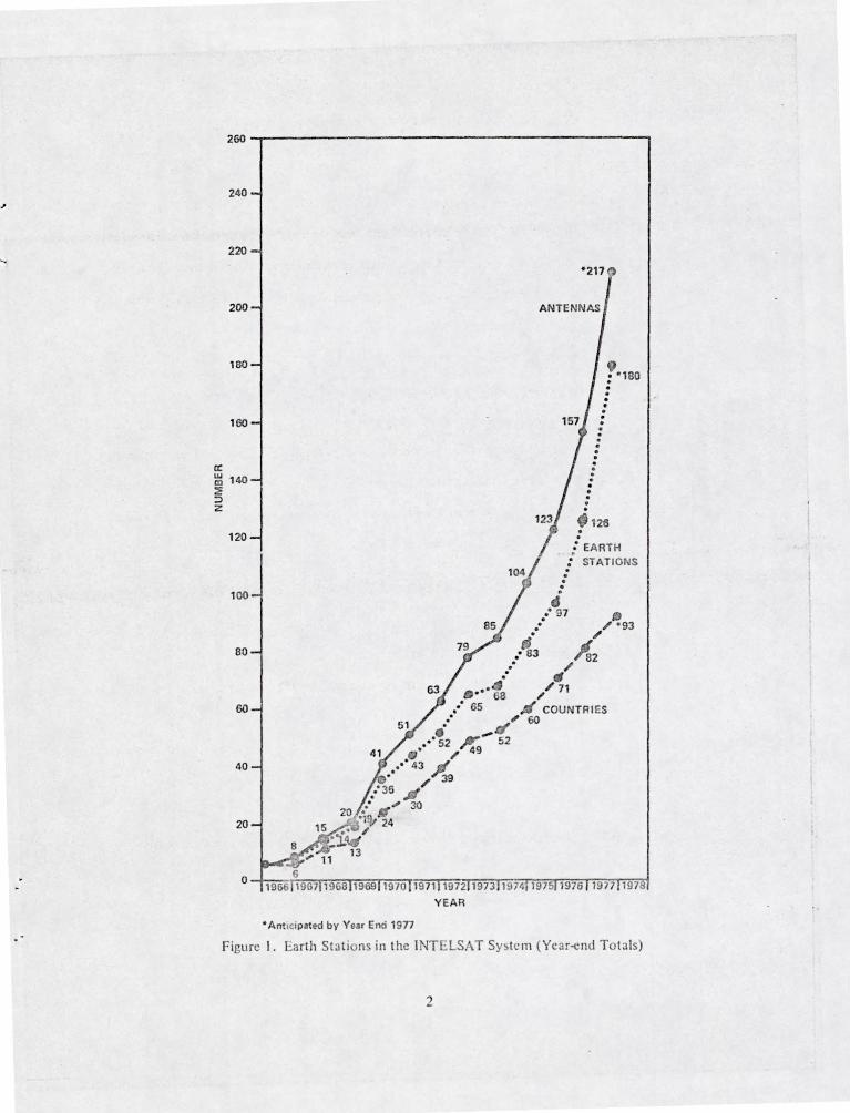
munications on a commercial basis. Some measure of the growth and international acceptance of
this technology can be seen from the rapid increase in number of earth stations in the INTELSAT
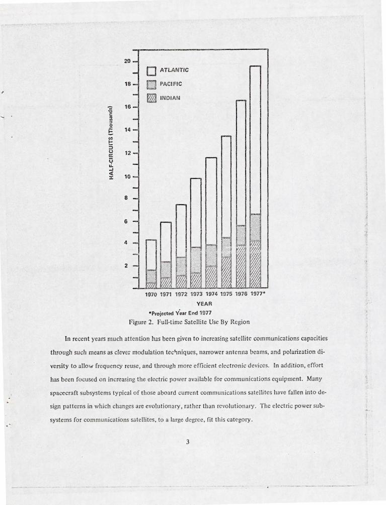
system, as shown in Figure I . Although television is perhaps the fonn of communication most
widely recognized by the general public, voice communications far exceed the traffic volume repre-
sented by television . This growth in service , characterized in terms of 4 Hz bandwidth one-
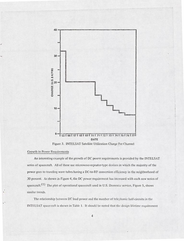
direction links, is shown in Figure 2. The cont inuing exponential growth undoubtedly has been
caused by a number of factors, including the red uctions in rates shown in Figure 3.
~ .: , , (
I
2~~----------------------------------------------~
240
220
200
180
160
100
80
60
40
20
. .
· · · · · · · · · · 126
:' EARTH : STATIONS · · · · ·
••••• ·97
" ·93
" .' 83 A2 . . . .
68
/ ,. /71 , COUNTRI ES
'60
• • ' 52 ?;' 52
.... 4; ,,49 "' 3~ .sf" 39
20 ... !IS" 30 '1!V 24
15 .' , ' '144
13
• Ant icipated by Year Enti 1977
Y EAR
Figu re I . Earth Statio ns in the INTELSAT Sy !e m (Ycar-end Totals)
2
/
-.. ~ a ::I 0 ~
t: '" !: ::> u a: U ~ ~
ct :J:
20
18
16
14
12
10
8
6
4
2
0 ATLANTIC
,; ::: PACIFIC
~ IND IAN
1970 1971 1972 1973 1974 1975 1976 1977-
YEAR
-Projected y'ear End 1971
Figure 2. Full-time Sate llite Use By Region
In recent years much attention has been gjven to increasing satelli tc communicat ions capacities
through such means as cleve, modulat ion tec~n iques , narrower antenna beams, and polarization di-
versity to allow frequency reuse , and through more effi cient e lectro nic devices. In addi tio n, effo rt
has been focused on increasing the electric power avai lable for communicat ions eq uipment. Many
spacecraft subsystems ty pica l of those aboard cu rrent com munications satel li tes have fallen into c1 e-
sign patterns in which changes are evolutiona ry , rather than rcvolut ionary. The electric power sub-
systems for communications s:ltellites , to a large degree, fit this category.
3
"
~~-------------------------------------,
30
a: 2:. ~ <h
ui 2 20 w (!I a: < :I: U
10
DATE
Figure 3 . INTELSAT SateJlite Utilization Charge Pe r Channel
Growth in Power Requirements
An interesting example of the growth of DC po,::er requirement is provided by the INTELSAT
series of spacecraft. All of these use microwave-repeater-type devices in which t he majority of the
power goes to traveling wave tu bes having a DC-to-RF conversion efficiency in the neighborhood of
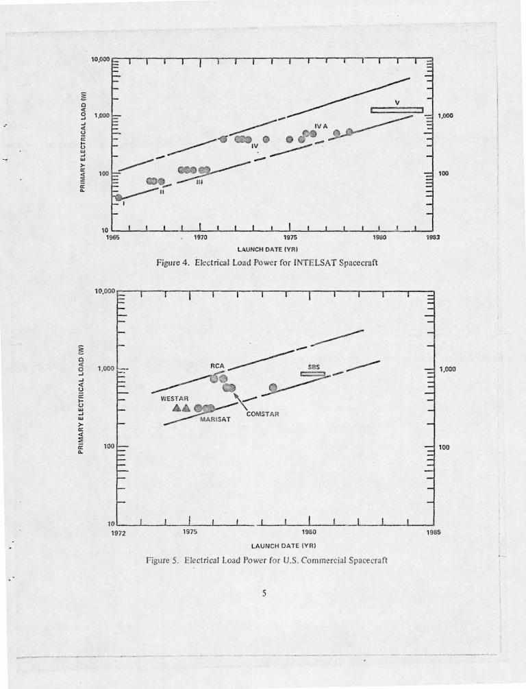
30 percent. As shown in Figure 4, the DC power requirement ha iJicreascd wi th each new series of
spacecraft. (I ) The plot of operationC11 spacecraft used in U.S. Domest ic service, Figure 5, shows
similar trends.
The relationshi p between DC load power and the number of telephonic half-circui ts in the
T ELSAT spac,ecraft is shown in Table I . It should be noted that the design IiI" time rcq uiremen t
4
~ 0 <I: 0 ..J
-- ..J <I: ~ ex: ~ u W ..J W
>-ex: <I: ~ ex: ...
~ 0 <I: 0 ...J ..J <I: (.)
ex: ~ (.) UJ ..J UJ
>-ex: <I: ~ ex: Q..
100
1,000
1970 1975
LA UNCH DATE (VR)
1980
Figure 4. Electrical Load Power for INTELSAT Spacecraft
1,000
100
7983
1,000
100
10~ __ ~ ____ L-__ -L ____ ~ __ ~ ___ -L ____ L-__ ~ ____ L-__ ~ ____ L-__ ~ ____ ~
1972 1975 1980
LAU NCH DATE (VR )
Figure 5. Electrical Load Power fo r U.S . Comm rcia! Spacecraft
5
1985
Year of 1st launch
Drum dimensions (err.) dia hght
Overall deployed height (em)
Mass (kg) at launch in orbit
Primary load power (w)
Active Transponders
No. of tel. circuits
Design li fetime (yr) ---
·No mUltiple access. **Incentive 7 yrs; design 10 yrs.
Table I
Growth of INTELSAT Spacecraft r--
I NT!:: LSA T Satelti.tc r--
I II III IV
1965 1967 1968 1971
72.1 142 142 238 59.6 67.3 104 282
528
68 162 293 1385 38 86 152 700
40 75 120 400
2 1 2 12
240* 240 1200 4000
1.5 3 5 7 .-
IV-A V
1975 '79 to '80
238 -282 -
590 1585
14 69 1870 790 1014
500 975
20 20-30
6000 12000 +2TV
7 7/10**
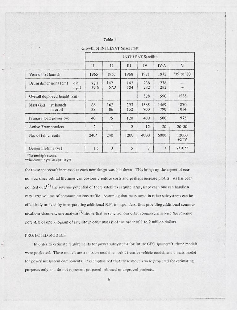
for these spact:craft incrl:!ascd as each new deSIgn was laid do wn. Tt.~s brings up the aspect of eco-
nomics, since orbital lifetimes can obviously reduce costs and perhaps in crease profits. As has b::en
pointed out,cn the revenue potential of thc <(! sa telli te is quite large , sin ce each on e can handle a
very large volume of commu nications traffic . Assuming that mass saved in other subsystems can be
e ffcctive ly utilized by inco rpurating JdditionJ I R.F . transponders, thus providing additional commu
nications channels·, one analysis(3) ~hows that in syndlronous orbi t commercia l service the revenue
potential of one kilogram of s<.Itdli[e in-orbit mass is of the order o f 1 to 2 million dolla rs.
PROJ ECT ED MODELS
In order to estimate requiremellts lo r power subsystems for future GFO spacecraft . t h ree models
wer projected . The c mode ls arc a mission model, on o rbit transfe r vehicle moud, and a mass modd
for pow r subsystem componen ts. It is empllasized tllnl these mode l: were projected for estim:Jting
purpo es only and do not rep rese n t propo d. plan :lccl or approvcJ projects.
6
... .
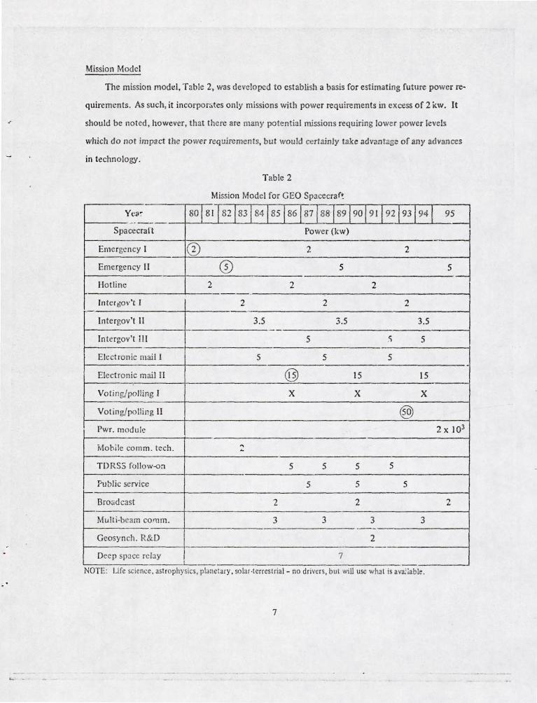
Mission Model
The mission modt!! , T able 2, was develo ped to establish a basis for est imating fu ture power re-
quirements . As such, it incorpor:>tes only missions with power requirements in excess o f 2 KW. It
should be noted, however, that t here are many po tentia l missions requ iring lower power levels
which do not impact the power requirements, but would certainly take advan tage of any advances
in technology.
T able 2
Mission Model fo r GEO Spacecra f~
Y(,a ~ 801811 82 1831 841851861871881891901911921931941 9~ _._-Spa cecra It
Pow" (kw) =d Emerge ncy I CD 2 2
Emergency II CD 5 5
Hot li ne 2 2 2 I - . ln tcr 60v' t I 2 2 2
.-
l ntergov' t II 3.5 3.5 3.5
In tergov 't 1II 5 .'i 5
Electronic mai l I 5 5 5
Elect ronic mail II @ 15 15
Vo ting/polling 1 X X X
Voting/polling II ® Pwr. module 2 x 10³
r.1obilc comm. tcch. '" ...
TDRS5 fo llo w-<> :l 5 5 5 5
Public service 5 5 5 i-
Broudcast 2 2 2
Multi-beam co ru m . 3 3 3 3 - -Geosyn ch. R&D 2
Deep space rclay 7
NOTE : Life science, astrophysi s, pbnetary, so lar·terrestrial- no drivers, but WIU usc whal is ava.::able.
7
TIlis model is a combination of ckmcnts from va rious sourccs.<4,5) The m ai n features 00-
served for th is mfJdel a rc :
I. Communications cO:1 tinue as the primary applicat ion fo r G EO . pacecraft.
2. Expansion of comrnunic:lI iom into IIt'W a reas is projected.
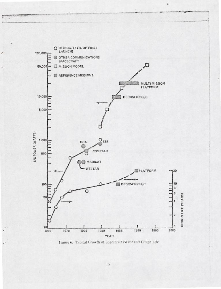
3. The h igh power driv~rs (circkd o n the mis. ion model) can be considered nominally as ex-
tensions of past power requirement trend s (sec Figure 6) . A reference dedica ted spaCi;:cra l!
and a refe rence multi·missio n platform . in JgreeJ11cn t Wilh th is model, were se lected fo r
furth er analysis.
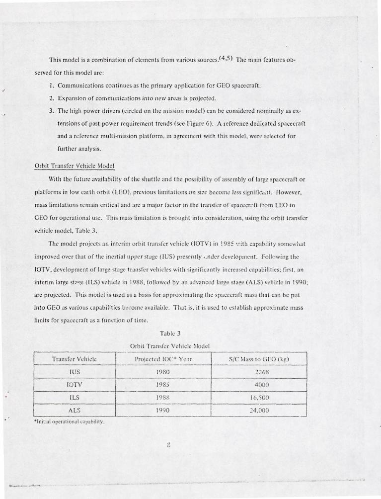
Orbit Transfer Ve hi cle Model
With the fu tllr' avai labili ty of t he shuttl e ant! the possibility o f a sc mbly of la rge pacecraft or
platfo rms in lo w cal th o rbit (LEO). pre ious limitatio lls on size become J.!ss !>ignific;...lt. However,
mass limitation rcm~ i n critical Jnd arc a major fac lor in the trans fe r of spacecr;-ft frem l EO \0
G EO for operational use . This m:Jss limi ta ti o n is brought in lo con id ' ra tion. lIsing the o rbit transfe r
vehicle model, Table 3.
The modd projects ar. intni m orbit tran:.fe r vehic k' (lOT ) in ! 92 S ':: :th apability som wha t
improved ove r that of ~he ine l1 ialllpJ)<.' r t:Jge (I US) presently •. lIder dcvd oplllcn t. following the
IOTY . devt:!opml'n t of l:l rge tngc tr~ l\ srer vehicles wil h ign ifiGllltly in cn.::! cd cap3tJilitics: fif'i t. an
inte rim large st:"W (llS) vehicle in 1988, followed by an ' dva ncl.!d la rge st ag~ (AlS) whiclc in 1990;
are projected. This model is used as a b'ls is for appro. imating the space raft rna :; th at ca n be Pllt
into GEO as va rio ll t:apabilities bl.' co mc ava il ab le. Tha t i . it is u cd to l.! tablish approximate mass
limits for spat:ccraft as a fllnction of time.
Table 3
Orbit Tr3 n ~rl.!r chick :-'Iodcl
Transfe r Vchick Projected fOC '" Y ~' , : r SIC las to CEO (kg
IUS 1980 2268
IOTV I
1985 4000
IlS 1<) H 16. -00
AlS 1990 I 24.000 -
· Initlal (lpcraliofl a l ,a pahillty.
o INTELShT (YR. OF FIRST LAUNCH)
OTHER COMMUNICATIONS SPACECRAFT
o MISSION MODEL
REFERENCE MISSIONS
~I
P I
J SBS
MARISAT
WESTAR
MUl TI·MISSION PLATFORM
DEDICATED SIC
PLATFORM ,/
// ~ "..
- . DEDICATED SIC
".:'
8
6
4
2
10~ ______ 4-______ 4-______ ~ ______ A-______ J-______ ~ ____ ~ 1 1965 1970 1975 1980 1985 1990 1995 2000
YEAR
Fi gure 6. Typica l Growth of Spacecraft Po ;vc r and Design Life
9
iii a: <t w ?: w u. :;j z 0 in w a
_____ . _ ~ ______ .... ____ __________ _______ _ .J ..
Mass Model for Power Subsystem Components
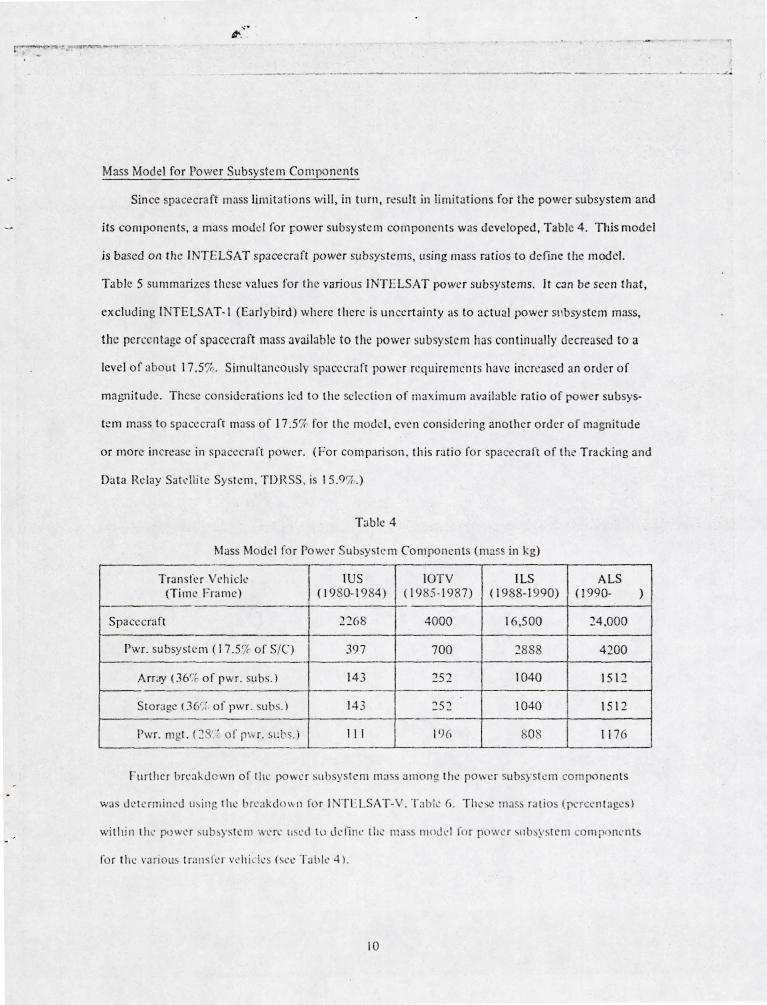
Since spacecraft mass limitations will, in turn, result in limitations fo r the power subsystem and
its components, a mass model for (:,owcr subsystem components was developed , Table 4. T his model
is based on the INTELSAT pacecrart power subsystems, using mass ra tios to define the model.
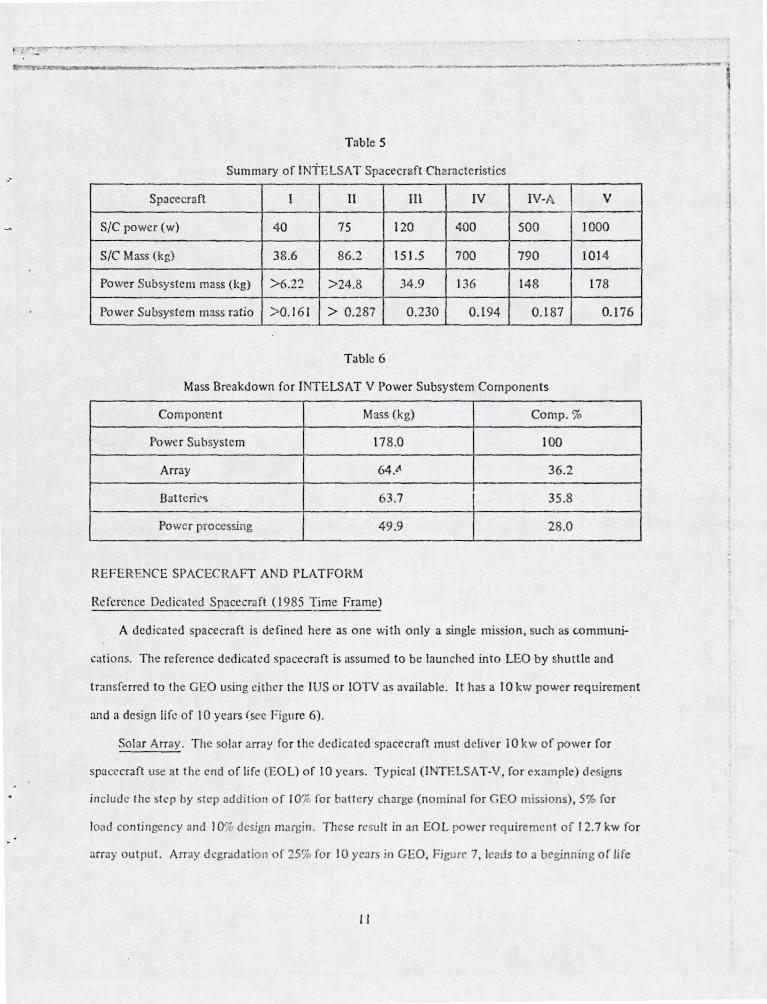
Tab le 5 summarizes t hese val ues fo r the various INTtLSAT power subsystems. It CJn be see n tha t ,
excluding INTELSAT-I (Ea rlyb ird) where the re is u ncert ainly as to act u;) 1 power sllbsyste m mass,
the percentagc of spacecraft mass avai lable to the power subsystem has con t inually decreased to a
level of about 17.5%. Simu ltancously spacc(;raft power requireme nts have incn:ased an order o f
magnitude. These considerations led to the selection of maximum availabh! ratio of power subsys-
t::m mass to spacecrJrt mass of 17 .57r for the mod ' I , even considering another order of m3gnitude
o r more increase in spacecraft power. (For comparison. th is ralio for spacecraft of the Tracking and
Data Relay Satdlite Sy tem. TDRSS, is 15.<)"( .)
Table 4
Mass Model for Power Sub y te m Components (ma s in kg)
Transfer Vehide IUS IOTV ILS ALS (Ti me Frame) (1 980-19 84) (19 85 -1987) ( 1988- 1990) ( 1990- )
Spacecraft 2268 4000 16.500 24,000
Pwr. subsystem ( I 7 S k of SIC) 397 700 2888 4200
Array (36r;~ of pwr. subs.) 143 252 1040 151 2
Storage (3 ';!. or pw r. ~ub s. ) 143 252 1040 15 12
Pwr. mgt. (2 ~'} o r pwr. !;l :tS. ) I I I 1% 08 1176
Further bre:1 kdc wn of Ihe po wer sllb y. tem mass amon g t he power subsys tem com ponents
was dete r! il1l'd u ~ i llg Ihe breakd ow n fo r I TELSAT-V. T able G. These mas~ r<l ti o jX'rcl' nt ages)
with in the p<)wc r . ll b yskn we n: II l' t! tu dl'l'i rle th' I11 J ~~ 111 od I.' I fo r powe r ~ lIb~ystl'm CO I1l P nl'n!.
for the V:.Jrlou.'t t ran"kr v ' h i I 's h ee T;J ble 41.
10
" . .,. ... --....... -...... ---------~-~---
Table 5
Summary of INTELSAT Spacecraft Characteristics
Spacecraft I II III IV IV-A V
SIC power (w) 40 75 120 400 500 1000
SIC Mass (kg) 38.6 86.2 151 .5 700 790 101 4
Power Subsystem mass (kg) >6.22 >24.8 34.9 136 148 178
Power Subsystem mass ratio > 0.161 > 0. 287 0 .230 0.194 0.187 0.176
Table 6
Mass Breakdown for INTELSAT V Power Subsystem Components
Component Mass (kg) Compo %
Powt!r Subsystem 178.0 100
Array 64.t\ 36.2
Batt erh' .. 3.7 35.8
Powef processing 49.9 28.0
REFER ENCE SPACECRAFT AND PLATFORM
Re ference Dedicated Spacecraft (19 85 Time Frame)
A dedica ted spacecraft is defmed here as one with only a single mission , such as wmmuni
cations. The reference dedicated spacecf3ft is assumed to be laun ched into LEO by shuttle and
transferred to the C EO using either the IUS or 10TV as available . It has a 10 kw power requirement
~md a design life of 10 years ~sec Figure 6) .
Solar Array. The solar array fo r the dedicated spacecraft must deliver J 0 kw of power for
spacecraft usc at the end of life (EOL) of 10 years. Ty pical (INTELSAT-V. for example) designs
include the step by step addition of 10% for battery charge (no minal for GEO missions) , 5% for
load contingency and I O"v design margi n. Thcse result in an EOL power requirement of 12.7 kw fo r
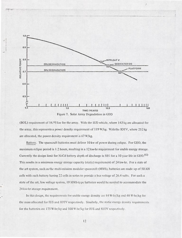
:lffayoutput. Array degradat ion or 25% for 10 year in CEO, Figure 7, leads to a ueginning or life
11
I __ I
1.0
0 .9
f£ 0 .8 ~ o ~ ...
--~-------
25% DEGRADA nON
:> 30% DEGRADAT ION ~ 0.7~--------~~~----~------------------------------~~--------------...J ... a:
0.6
0.5
1~ __ ~ __ ~~l~~I~II~ __ ~~~I~I~I~I~I~I~I~ __ ~~~~~lID ~. 1 1.0 10.0 l Oa
TI ME (YEARS)
Figure 7. So lar Array Degrada tion in GEO
(BOL) requirement of 16.Q5 kw for th array . With the iUS veh icle, where 143 kg are allocated for
the array, this represen ts a power de nsit y requiremen t of I 19 W /kg. W;th the IOTV, where 252 kg
are allocated, the power density requ iremen t ;s 67 W /kg.
Batt ery. The spacecraft bJtt ' ries must delive r 10 kw o f power during eclipse. For GEO, the
max imum eclipse period is 1.2 hours, resu lting in a 12 kw-hr requ irement fo r usable energy storage .
Currently the design limit fo r i-Cd battery de pth of discharge is 50'i{ for a 10 year life in GEO .(6)
This resu lts in a minimum energy storage capacity (static) requiremen t of 24 kw-hr. Fo r a tatc of
the art system , slich as thl~ multi-mi ion modu l;]f pacecra t (MMS) , b:l tterics are made lip o f 50 AH
cells with each battery having 22 cells in s' ri es to provide a bus vollage of 26.4 volts. For such it
state o f the art , low voltage sy tern , 19 l\IMS-typc batteries wou ld be needed to accom modate the
24 kw-hr storage reqtl ir ment.
Tn this design, the requiremcnts ro r usable eJl~ rgy de nsi ty :lre 84 \V-In/kg and 4 W-hr/kg fo r
the maSS al lo :l Ied fo r J Sand IOTV rcspe ' livel y. Simila rl y . the sta tic 'Iler!; dell it . rl'quin:menls
ror th e natterics arc J 75 W-hr/ k ' and 100 W-hr/kg ror IUS ;JI1cl IOTV rcspcc l i,·l.'!y.
L
...... ~---------. ...-.--"".---~-~-- - --------_._---
Power Processing. The power to be processed within the spacecraft is 10 kw. Dissipation of
excess power, prior to radiation degradation, or resulting from factors such as overdesign or failure
of portions of the payload are not included in this figure.
Density requirements for power processing are 90 W /kg (11 kg/kw) and 51 W / kg (20 kg/ kw)
respectively for the IUS and IOTV mass allocations.
Re ference Multi-Mission Platform (1 985- 1990 Time Frall1e)
A multi-mission plat fo rm is defined here as an assemhled platform to which a variety of equip-
menls designed to perform :l variety o f missions (services or fu nctions) are moun ted. Several sub-
systems su <.:h as those for station keeping, attitude cont ro l and power can be uti lized in common.
The reference platfurm. as with t!1e ded:ca ted spacecra ft, is assumed to be launched by shuttle and
assem bled in LEO. It is then transferred to GEO by the IOTV. the ILS or the ALS as available. It
is defined to have a 20 kw power requi rement and a design life of 20 years (see Figure 6).
Solar Array. The spacecraft load of 20 kw leads to an EOL requirement of 25.4 kw fo r the
array , using the salTle additional ba ttery charge , load contingency and d sign margin as for the ref-
erer.ce d dicated spa c aft. In this case, however, for a design life of 2C years, a degradation of
30% (see Figure 7) leads to a BO L requirement of 36.3 kw. Array power density requiremen ts are
found to be 144,35, and 24 W/kg fo r tr IOTV, ILS and ALS respect:vely .
Energy Storage .· For a 1.2 hour eclipse the 20 kw load results in a 24 kw-hr ene rgy discharge.
Tllis, in turn , leads to total energy storage requirements of 48 kw-hr with a 50% discharge allowance
or 30 kw-hr if an 80% di scharge allowance is at tained. I n ei ther ca~ , the usable energy density re-
qu irements are 95, 23, and 16 W-hr/~g for IOTV, ILS and ALS respectively. However, static energy
density requirements an: 190,46. :lnd 32 W-hr/ kg for a 50';~ depth of discharge and 11 9,29, and
20 W-hr/kg for an 8()j; depth of d i char;;c for the respect ive transfe r vehides.
Power Processing. ror the 20 kw platform req uirement , the allocated mas.<,es fo r power proc-
essing lead to density requi /l'ments of I O~ \\,/kg (9.8 kg/k w), 25 W /kg (40.4 kg/kw), and 17 W /kg
(58. 8 kg/k w) for the IOTV . I LS, and ;\ LS rcspect ively.
· The .:h:l ngc in termll1ology (rom "battery" to "energy sto rage" ha~ been intentional in recogn ition of the possibility that an alternat ive storage syst em will be used for the platfo rm .
13
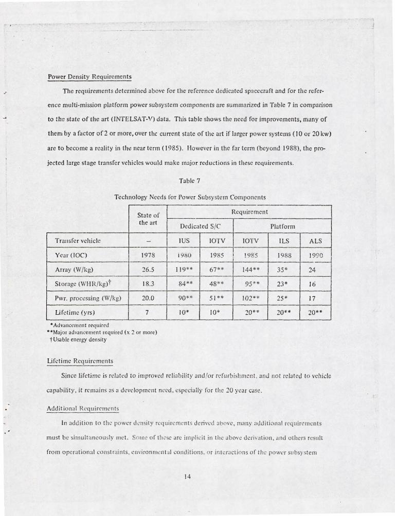
Power Density Requirements
The reqlliremel ts determined above for the reference dedic3ted spacecraft 3nd for the refer-
ence multi-mission platform power subsystem components are summarized in Table 7 in comparison
to the state of the art (INTELSAT-V) data. Th,is table shows the need for improvements, lTIany of
them by a factor of2 or more, over the current state of the art if larger power systems ( 10 or 20 kw)
are to beco me a reality in thl! ncar term (1 985), I lowever in the far term (beyond 1988), the pro-
jected large stage transfer vehicles would make m:ljo r reductions in these requirements.
T3ble 7
Technology Neec!s for Power Subsystem Components
State of the art
Transfe r vehicle -
Ye3r (lOC) 1978
Array (W Ikg) 16.5
Storage (Wl-IR/ kg)t 18.3
Pwr. proccssing (W/kg) 20.0
Li fetime (yrs) 7
• Advancement required "Major advancement required (x 2 or morc) t Usable energy density
Li fetime Requirements
Requirement
Dedicated SIC
IUS IOTV IOTV
198CJ 1985 I !985
11 9** 67** 144**
84* * 48"'* 95 "*
90 H 5 I "'* 102**
10* 10· 20 **
Platform
ILS
1988
35*
23*
25·
20**
ALS
1990 .-
24
16
17
20**
Since lifcti me is rela(ed to improved reliability and /or refurbishment, and not relalt'd to vehicle
capability, it rcmains as :J deve lopmcn t need. espcci311y for the 20 year case .
Addition al RL'quireme nls
In addition to the power lknj ly rcqu ircITll' nl s deri ved :Jl Iwe, many additi 0n:t1 rl'qu irclllcnt s
must be ~ imlllt :Jneoli l y l11e\. :' o lnc of t il ' se are illlpli 'il in the above (kriva tion, Jnd olhers rc lilt
from operationa l consl rai nls . eJl\'ironl1lent :.l1 condi ti ons. or in(cr:J ctions of th t: power subs} stem
14
j
--~--.----- "... . -.. - -
... :ithin itself, with other subsystems, with the pacecraft ::nd with the environment. Since these are
already familiar requirements, they are listed below without elaboration.
Solar Array
I. The solar array must provide standby and housekeeping power fOT the spacecraft during
transfer to CEO.
2. Array deployment (and probably retraction for dedicated spacecraft) is rcquired .
3. The array must be orientable toward the sun, minimizing dynamic interaction with the
spacecraft.
4 . The array must sl..rvive thermal cycling during eclipse. Cycling will be approximately from
+50°C to -200°C, with 880 cycles experienced by the 10 year spacecraft array and 1760
cycles experienced by the 20 year plat form arr.:!y .
S. The array must produce 17 kw of power (BOL) and 12.7 kw (EOL) for the 10 kw dedicated
spacecraft and 36.3 kw (BOL), 25.4 kw (EOL) for the 20 kw platform.
6. Maximum rI,..~r'l.cla ion for the spacecraft is 2::ir;~·1 IO .::,,,:> life and for the platform is ~O%
in 20 years life .
Energy Storage
J. The encrgy sto r.1ge component of the power subsystem must provide 12 kw-hr of usable
energy for t he 10 kw spacecraft and 24 ky. -hr of usa ·)Ie encrg for the 20 kw platform.
2. It must provide energy for 880 and 1760 cycles, for the spacecraft and platforms respec
tively , at depth of discharge and operational temperature (for example, 50%, 15°C max. for
Ni-Cd batteries).
3. Between discharge cycling, it must sto re energy for periods of 5 months each and at oper
ating temperature, 20 periods for the spacecraft and 40 periods for the platform.
Power Processing. The power processing equipment must accommodate the following:
1. It must transfer 17 kw of power across the alTay/spacecraft in ter race or 36 kw of power
across the array/platform int rfacc and distribllte it within the spacecra ft or alternatively to
variolls mis ion modules on the platform an d then within the moduJ s as required .
15
-'
2, It must dissipak excess array power (7 k w SOL on the spacecraft, 16.3 kw SOL on the
platform).
3, [t must control bus voltages , which may be either regulated or unregulated, and regu late
equipment voltages.
4. It must provide switching (high or low voltage; AC or DC), sensing, and fuzin g as required.
5. It must perform at high e:,'"; ··i<:ncy.
Thermal Control. Tp -..: rmal control of t11l' subsystem COl11pOnl'nts is required to provide for the
following fun ctions.
I. Minimize a rray temperaturl' fo r bcst cflkicilcy.
2, Control battery tcm pcratlln: within rcqllirl'u limit : (O°C - I SoC for Ni.('d batteries).
3. Dissipate waste heat from :
(a) Array I' XCCSS power i40'l; )
(b) Battl'ry ineffi ciency ('20";' )
(c) Processing Inefficiency ( I S'k )
Subsystem Requiremen ts
I. The power subsyste m mllst bl: stahle for the bunch, transfer, and orbital environment, in
cluding orbital pIa ma eCfects related to spacccrJft charging or to high voltage/plasma
interactions.
2. All components of the power subsyst e m mllSt be safe ollring fabrication and test (handling),
safe for shuttlt' (maf1f1l'd) la unch , and safe during docking :lJld assembly operations.
FUTURE ADVAN ES IN TEClINOLOGY
Solar Energy C(Jnvc rsio l~
Sevrral impo rtant technol gy changes th nt have significan t impact on the mass and con ersion
efficiency of photovoitaic a l rays w -re pionee red ill the labora tory during the last decade. Thcs.: arc
gradually being arplied on opeDt ional . pacecrai'l as t he ~ 1 progr.: S I hrough the ste ps of producti o n
procc5s refi nemen t , flight on 311 C . peri m ' Il t:Jl ba is, and finally a<; they a rc fuily qualified by tc (ing
and certified fo r ope rational usc .
16
-------- ------_._-- ------ .. --... ~ .. -
Solar Cells . The silicon photovoltaic cell had reached a rather stable design status with a con
version efficiency plateau of about 101,12 percent in the mid 1960's. Some detailed analysis of the
sources of energy loss wi bin the cell(7) high-lighted promising areas for improvements in perfor
mance. At thc same time, a laboratory development effort at COMSAT produced a new silicon cell
called the "violet cell. ,,(8) This triggered a new burst of silicon cell development(9) which has pro
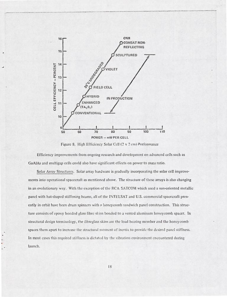
duced laboratory cells having conversion efficiencies as high as 15 1,11 percent, Figure 8.
These laboratory ~::velopments on the silicon cell component are now being exploited rather
rapidly in operational programs. The hybrid type cell has already been used in a variety of space
craft programs, and cells closely approaching a 20 mw/cm 2 level have been flown on the NASA Inter
nation al Sun-Earth Explorer spacecraft. The USAF recently supported an extensive qualification
program for the 80 milliwatt, textured cell (sometimes referred to as the K7 cell) which is now being
supplied for operational use in the SBS and ANIK-C satellite programs. Of course, the mass and area
of solar arrays using these highcr efficiency cells can be reduced nearly in proportion to the efficiency
ratios. In some cas~s the gains are slightly less, due to higher electron degradation rate5 or incr ased
operating temperatures.
Another exciting po~ibility, which is still in the laboratory stage at tIllS point, is the SO micron
(2 mil) thick ·ilicon cell. The development work on this component U: being sponsored by NASA
through JPL.(I0) Conventional cells have a power to mass ratio of about lOOW/kg when they are
covered with an equivalen t thickness of quartz. By contrast, these new thin cells have the potenti:!l
of producing about i 000 \ /kg bare, and if SO to 100 micron covers can be produced and handled,
couid possibly achieve something in the vicinity of 300 to 500 W /kg c')vcred. In both cases above ,
the mounting and inter onnect ion provi.~jons are not incJud d ill the mass. However, a great deal of
laboratory work remains to be done to learn how to routinely manufacture, cover, mount, and in
terconnect th ese I:clls. Of course the actual power to mass ratio for practical arrays is considerably
below these figures due to the weight of materials and structures needed for interconnecting, sup
porting and deploying thr solar cells as discus cd below.
17
------------- _._--------
16
15
I- 14 $ Z ~ w
(.J 0~ a:: w 9«1 Q.. 13 ~~ I > oV <.J ~ Z w 12 ~ v.. u. IN PRODUCTION w
~ ...J " ...J W (.J
10
POWER - mWPER CELL
Figure 8. High Efficie ncy Solar Cdl (2 x 2 eq)) Pf" rforrnance
Efficiency improY.:ments from ongoing research and development on advanced cells such as
GaAlAs and multigap cells conld also have significant cffects on power to maS$ rat io.
Solar Array Structures. Solar array harJwarc is gradually incorporating the solar cell improve-
men ts into operational spacecraft as mention d above . The structure of these nrrays is also changing
in an evolutionary way. With the excep tion of tn\.' RCA SA TCOM which used a sun-oriented me tallic
panel with hat-shaped stiffening beams, all of the I. 'TELSAT anJ U.S. commercia l spacecraft pres-
ent ly in orbit have been drum spinn 'rs with ,I :lon.:ycomb sandwich panel construction. This struc-
turc consists o f epoxy bonded glass fibre skins bonckd to a v.:nlcd aluminum honeycomb spacer. In
stmctural d sign terminology , t!lC librl'glass kins ;Jre the load beari ng member and the hon eycomb
spaces them apart to inen:ase the slrudural moment of inl.'flia to provid . the desi red panel st iffness.
In most cases this requ ired st iffI1l.:ss is Lli tated by the vibration envi ronml!nt encountered during
launch.
18
--_._---- -
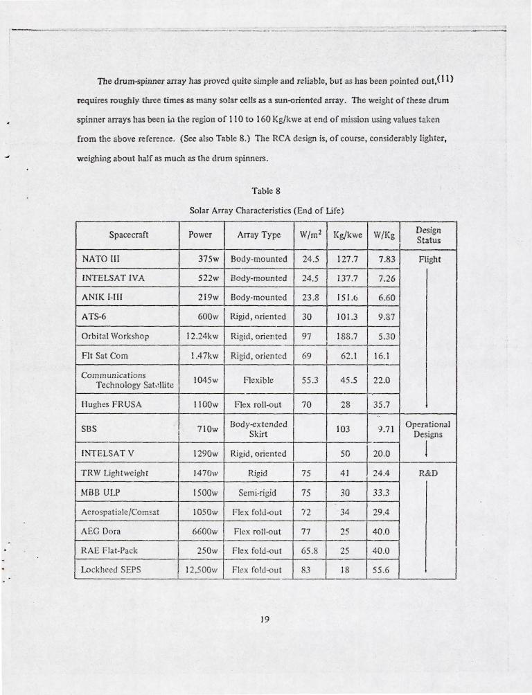
The drum-spinner array has proved quite simple and reliable, but as has been pointed out, (11)
requires roughly three times as many solar cells as a sun~riented array. The weight of these drum
spinner arrays has been i.1 the region of 11 0 to 160 Kg/kwe at end of mission using values laken
from the above reference. (See also Table 8.) The RCA design is, of course, considerably lighter,
weighing about half as much as the drum spinners.
Table 8
Solar Array Characteristics (End of Ufe;
Spacecraft Power Array Type W/m2 Kg/kwe W/Kg Design Status
NATO III 375w Body-mounted 24.5 127.7 7.83 Flight
INTELSAT IVA 522w Body-mounted 24.5 137.7 7.26
ANIK I-III 2 19w Bod y-mou n ted 23.8 151.6 6.60
ATS-6 600w Rigid , oriented 30 101.3 9.87
Orbi tal Wo rkshop 12.24kw Rigid , oriented 97 188.7 5.30
FIt Sat Com 1.47kw Ri gid, oriented 69 62. 1 16.1 I Communications 1045w FI xib le 55 .3 45. 5 22.0 Technology Sat,!lIite
Hughes FRUSA 1100w Flex roll~ut 70 28 35.7 ..
SBS 710w Body-extended
103 9 .71 Operational Skirt Designs
'- I INTELSAT V 1290w Rigid , oriented 50 20.0
TRW Lightweight 1470w Rigid 75 41 24.4 R&D
MBB ULP 1500w Semi-rigid 75 30 33.3
Aerospatiale/ComS1t 1050w Flex [olu-<>ut 72 34 29.4
AEG Dora 6600w Flex roll -<> ut 77 25 40.0
RAE Flat-Pack 250w Flex fold-<>ut 65.8 25 40.0
Lock heed SEPS 12,500w Flex fold~ut 83 18 55.6
19
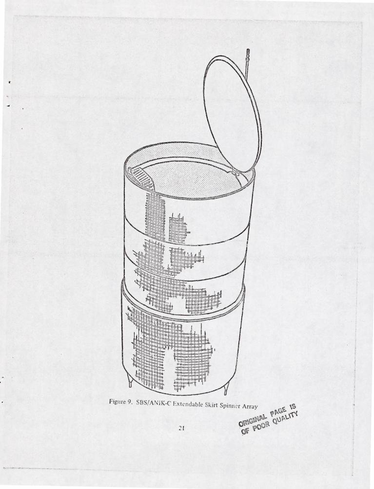
As the payoffs in mass reduction of these commercial satellites have come to be recognized,
the new array structural designs have begun to reflect some of the aerospace industry advancements
in lightweight structures. For instance, the SBS and Anik-C drum spinner designs with extending
skirts, Figure 9, now underway at Hughes Aircraft Co. are planned to have an epoxy- onded Kevlar
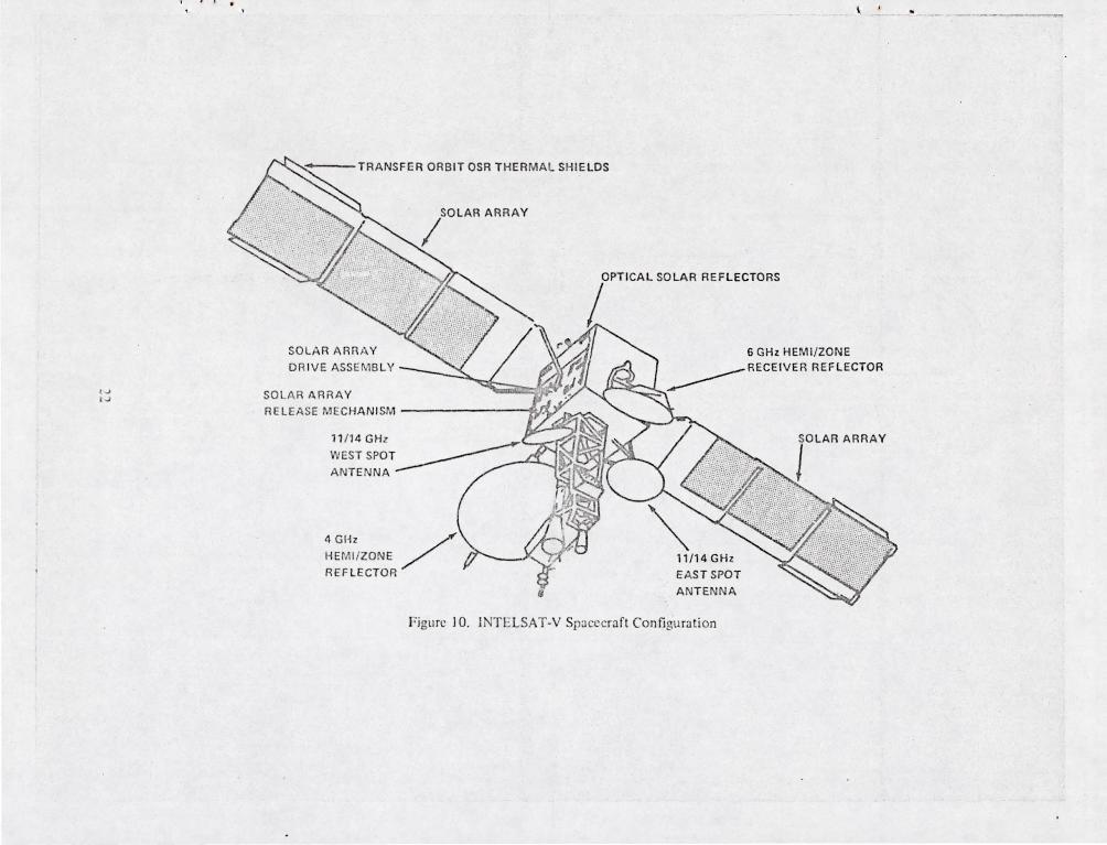
high strength to weight ratio fibre in the face skins. In another example, the INTELSAT V solar
arrays, Figure 10, which are presently in the fabrication and testing stage use woven graphite fibres
in the epoxy composite skins. In th is case a Kapton layer is placed under the solar cells to insulate
them from the conductive graphite.
The laboratory developments, listed in the lower portion of Table 8, in combination with the
solar cell advancements mentioned earlier offer high promise for continuing area efficiency and
power density improvements up to an order of magnitude or so better than the present operational
designs. fuch of this imprm ~m nt will probably result from elimination of much of the substrate
weight by moving to semi-iigid or flexible substrate concepts of the types investigated in the ongoing
R&D work. Current R&D d':~i:;~s of flexible roHoOnt and Oexible fo!.-I..n!,~ arrays are in the 30-60
W/kg (34-18 kg/kwe) power density range and the future possibility of arrays with power densities
of 110 to 200 /kg has bren indicated in cont;cptual design studies.(I2)
Energy Storage
Ni-Cd Batteries. The rechargeable nickel-cadmium (Ni-Cd) alkalinc cell has been used to supply
primary power during eclipse in all of the U.S. domestic and INTELSAT communications spa ecraft
flown to date . In particular, the backlog of orbital experience, high-rate deep-<lischarge capability
and long storage life :lppear to be key qualifi ations of this type of cell.
Detailed analysis of a number of bCltteries designed [or these geosynchronous orbit missions rc-
veals that thc to tal energy density ava ilab l from new cells at 100 perc nt depth of discharge is rela-
tively constant at about 26 watt-honrs pcr kiiogram. The cell wl'ight comprises abou t 82 perexnt of
the weight of a typ;cal flight battery, with the wiring, conllcctors, electronics and structure making
up the remaining 18 percent.
:0
Figllre 9. SUS! ,' il\:-(' I-.xtl' ndab le Sk irt Spinn(' r Array
~ I
, .... ,..)
\
TRANSFER ORBIT OSR THERMAL SHIELDS
SOLAR ARR A Y
D RIVE ASSEMBLY
SO LAR ARRAY
SOLAR ARRAY
I
RELEASE MECHAN ISM ~
4 GHz HEMI/ZONE ./
REFLECTOR /
OPTICAL SOLAR REFLECTORS
L 6 GHz HEMI/ZONE
.._______RECEIVER REFLECTOR
'1/14GHz EAST SPOT
A NTENNA
fLAR ARRAY
Figu re 10. JNT ELSAT-Y Spacecra ft Configu ration
-_ ... _-_.--
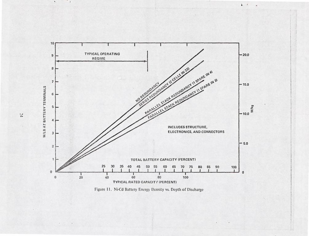
Typically, from one-third to one-half the power subsystem mass in these spacecraft consists of
batteries. The principal variables which determine the delivered energy density are the actual depth
of discharge used and the redundancy strategy. This is shown graphically( I) in Figure 11 . Most of
the U.S. commercia l and INTELSA T craft have used the series cell redundancy approach and have
been operated in the discharge range of 35 to 55 percent of total electrochemical capacity as a max
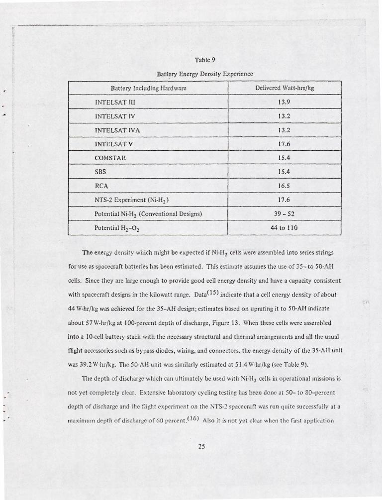
imum. The energy density ill terms of actual watt-hours/kg delivered to the load during the longest
eclipse is shown in Table 9 for a number of these spacecraft.
In-orbit reconditioning(l3) is allowing longer mission life and c!eeper d ischarging of t he Ni-Cd
batteries in newer designs, resulting in the somewhat higher energy densities (see Table 9) for cur
rent spacecraft . It is hoped that additiona l R&D in tliis area will allow some further increment:d
improvements in lifc and energy density of Ni-Cd batteries in future designs.
Nickel Hydrogen and Othcr Advanced Couples . Advanced electrochemical energy storage de
vices which offer improvements in energy density have been investigated for a number of years. Of
the large number of possible systems, the low-tem peraturp. Ni-H;< ?- k. 1!1C systerr. presently appears
to possess the best near-term potential for synchronous orbit use.(l4) TIlcse hermetically sealed
secondary cells can be regenerated electrically, and require no pumps, or other moving parts. In
addition, they have the high-rate discharge capability needed for operation in synchronous orbit
spacecraft. TIle electrolyte is an aqueous so lution of 3S-percent potassium hydroxide.
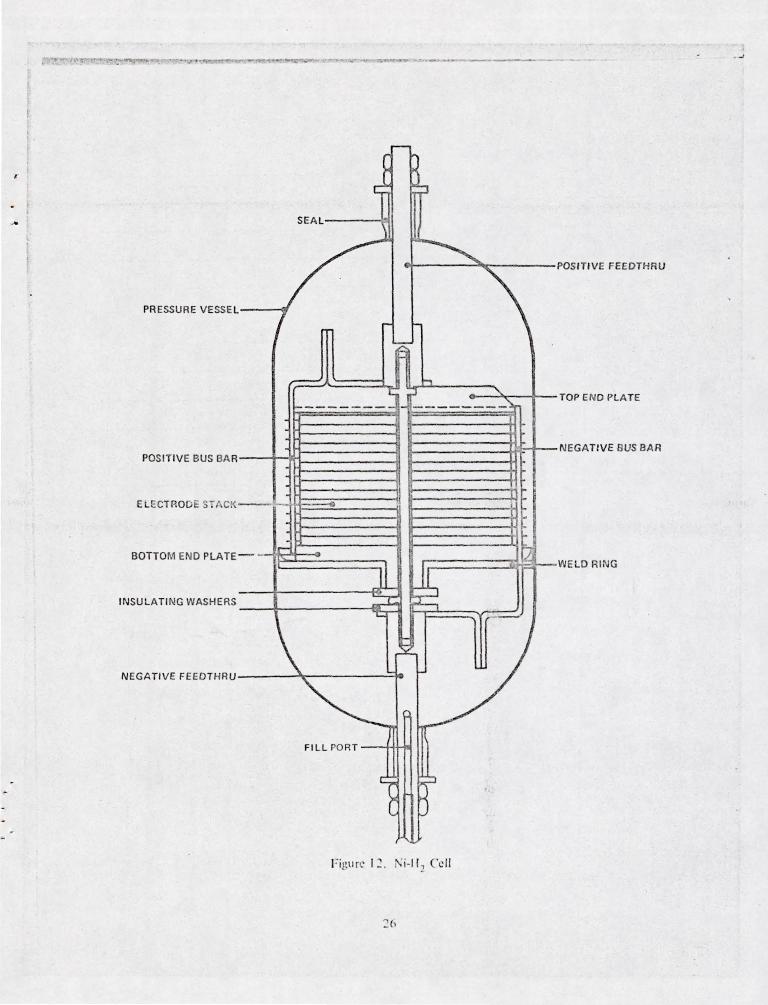
A typical physical arrangement of these new Ni-H2 cells is shown in Figure 12. A single-cell
design is being pursued in this work for a number of reasons. It offers a high energy densi ty and is
advant2gcous in terms of reliability, since leaks or electrical faults can be isolated to a single cell by
using diode bypassing techniques . Somc extensive analytical work has been conducted to evaluate
the energy density that can be achieved in practical designs of these single-cells. Specifically, com
puter models of the li-H 2 cells have been developed for parametric study. Further practical designs
and fabrication studies, including structural and thermal aspects, havl been done, including the
appropriate testing.(lS}
23
10
9
8
7
VI -1 <f Z 6 :? cr w ... >- 5 a: w
' oJ ~ ~
< 4 CO ... <f CO -1 3 --~
o o 20
TYPICAL OPERATING
REGIME
40
INCLUDES STRUCTURE,
ELECTRONICS, AND CONNECTORS
TOTAL BATTER Y CAPACITY (PERCENT)
6{) 80 100
TYPICAL RATED CAPACIT'{ (PERCENT)
figure 11. Ni-Cd Battery Energy Density vs. Depth of Discharge
20.0
15.0
10.0
5 .0
o
CI oX
~
--------.--------- ------
Tab le 9
Battery Energy Density Experience
Battery Including Hardw:lre Delivered Watt-hrs/ kg
INTELSAT III 13.9
INT ELSAT IV 13.2
INTELSAT IV A 13 .2
JNTELSAT V 17.6
COMSTAR 1 S.4
SBS 15.4
RCA 16.5
NTS-2 Expe riment (Ni.H2) 17.6
Potent ial Ni-H 2 (Conventional Designs) 39 - 52
Po tential H2-02 44 to 110
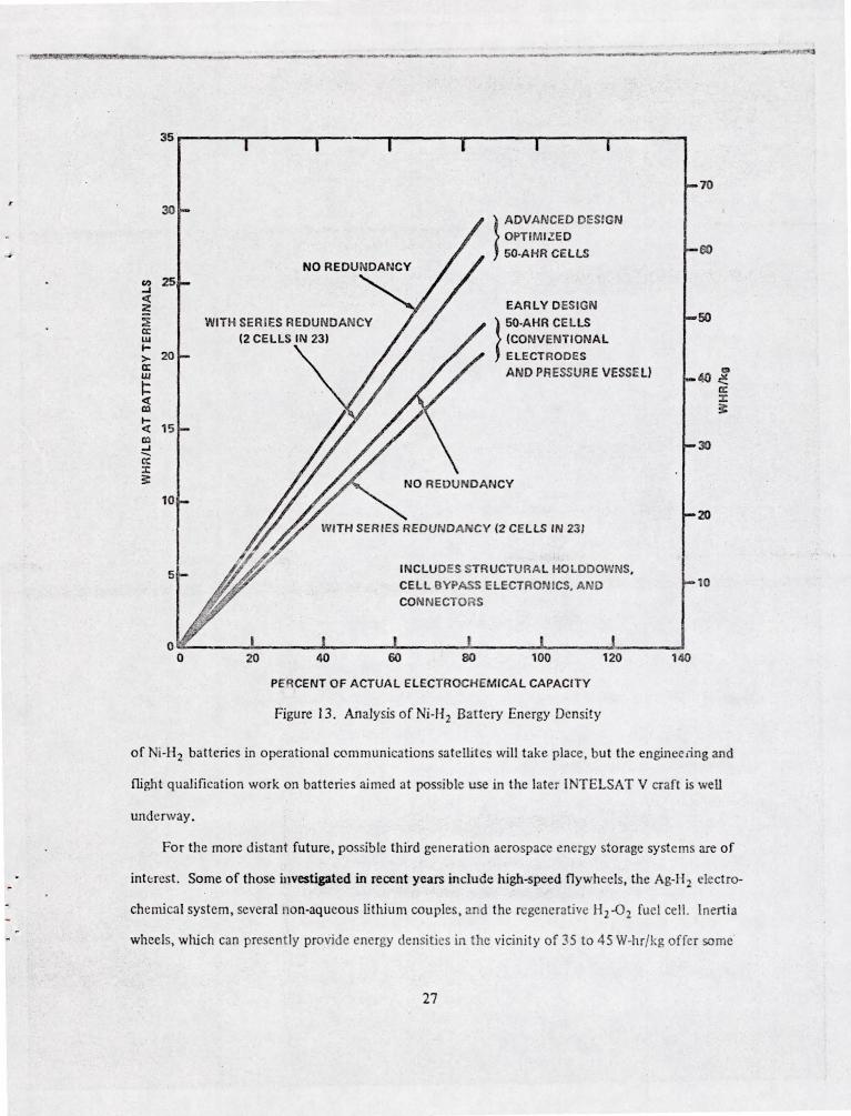
The ener!;), del sity which might be t! xpected if Ni·H2 cells were assembled into series st rings
for use as spacecraft batteries has been estimated. T his estimlte assumes the use of 35- to SO-AH
cells. Since they are large enough to provide good <.;eIl energy density and have a capacity consistent
with spacecra ft designs in the ki lowatt range. Data(1 5) indica te tha t a cell energy density of about
44 W-hr/kg was achieved fo r the 35- AH design; est imates blsed on uprat ing it to 50-AH indicate
abou t 57 VI-hr/ kg at I DO-perc nf depth of discharge , Figure 13. When these cells were assembled
into a lO-ccll battery stack with the necessary st ructural and thermal arrange ments and all the usual
fligh t accessories such as by pass d iodes, wiring, and co nnectors , the energy densi ty of the 35·AH unit
was 39.2 W-In/kg. The 50-AH un it was similarly est imated at 5 1.4 W-hr/kg ( ee T able 9).
The depth of d ischarge wh i h can u ltimately be used wi th Ni-H 1 cells in operational missions is
not yet completely clear. Ex tensive labo ratory cycling testing h as be n done at 50- to gO- percen t
de pth of discharge and the fligh t experi ment on the NTS-~ spacecraft was run quite successfully at a
maxi m um depth o f dis hargc or 60 pcrcent. ( 16) Also it is not yet clear when t he firs t application
2S
....
-r ~ ~ SEAL
~~ P OSITIVE FEEDTHRU
PRESSURE VESSEL
/ h
"00-
"...-- h r: ;:r "- TOP END PLATE
~-------- ------- -
NEGATIVE BUS BAR POSITIVE BUS BA R
EL ECTROD E 7 AC .
H~
BOTTOM END PLATE
INSULATI NG WASHERS
=rr-, - - Ir- [2
JL ~ ~ -;:::::::::. 't:
WELD RIN G
NEGATIVE FE EDTHRU \ ~
L-
~ FILL PO RT
1 ~ Figurc l: . i\i. lf ~ 'clf
35~------r-------y-------~------~--------r-------'--------'
20 40
}
ADVANCED DESIGN
OPTIMI.!E D
50-AHR CELLS
EARLY DESIGN
}
50-AHR CEL LS
(CONVENTIONAL
ELECT RODES
AND PR ESSURE VESSEl)
INCLU DES STR UCTllRA l t1OLDDOWNS ,
CEL l SYPASS E LECTRON ICS, AND
CONNECTORS
60
PEqCENT OF ACTUAL ELECTROCHEMICAL CAPACI TY
Figure 13_ Analysis of Ni-H2 Battery Energy Density
140
of Ni-H2 batteries in operational communications satellites will take place , bu t the engineeiing and
fli ght qualification work on batteries aimed at possible use in the later INTELSAT V craft is well
underway .
For the more distant future, possible third generation aerospace energy storage systems are of
interest. Some of those investigated in recent years include high-speed fly wheels, the Ag-H2 electro-
chemical system, several non-aqueous Ethium couples, and the regenerative H2 -02 fuel cell. Inertia
wheels, whjch can present ly provide energy de nsities in the vicinity of 35 to 4S W-hr/kg offer some'
27
r
hope of higher performance with advanced materials. However, their inertial and reaction torques
are a significant problem in many of the spacecraft applications. TI;e advanced electrochemical
systems appear to be a fruitful area for invention and innovative design idea. For instance, vatlous
forms of the regenerative li2 -02 fue l cell demonstrated in the laboratory under several NASA-,
USAF-, and JNTELSAT-slIpported R&D programs have an attractive energy density in the vicinity of
100 W-hr/kg or more. An innovative approach which solves the pressure control and other reliability
problems of this cell could represent a significan t breakthrough in energy storage for aerospace
applications.
CONCLUSIONS
I. TIlerc has been a rapid expan ion in the u e of geosynchronous equatorial orbit , especially
for communications spac' raft.
2. Communications pacecra t have placcd continually more stringent requirements on the
power subsystems. both for tot al power load and for power density.
3. Projection int :} t c fllturo:' ~h ows thc nct!G for n~::jo r i nfJiv 'c.,.ent i . puwer densi ty in aU
three component (power con ersion, energy storage, power processing) of the power sub
system. It is anticipated th.lt dedicated mission commercial spacecraft in the multi-kilowatt
rang' will be designed in rip Ill:xt 3 - 5 years.
4. Proj~c'ed needs in terms of rower density or l.ncrgy densi ty are strongly dependent on orbit
transfe, vehicle Jpab ili[ies.
5. Asst.:ming transfer vehicle: de:\'e lopments arc rcalilcu w;tll thl.! high growth ra tes of the pro
jected model us d:
(a) Launch of a J 0 kw spa 'ceraf! prior to 198R wOtllJ sti ll rcquin: major improve ments in
eac~ of the rower componen ts. !\vJil;lbilil . of:t technology ready Oexible roll-out or
nexibl' fold-ollt ~rrJy in 19H5 i. a hey ckln,'nl ill rctlll ing Ill.:: necd in array power
den. ity to one of minor illlpro\'l:nll:n l.
(b) Launch of;, '20 kYo' platform <I~ carly ;1'; 19R (doi~1l in 1985) may be fc;) . ibk by <lllo-
eati ng "cxcess" ;\1 r~)' rna~~ to e l1er~y to rJgc and powe r procl!ssing.
28
(c) Advent of an advanced large stage orbit transfer vehlc e (ALS) at a very early date with
capabilities projected in the model would all but eliminate mass restrictions for the
power subsystem components in the power rar ge considered. However, in the more
likely event that only the IOTV or possibly ILS are available in the needed tIme frame,
significant power system advances are requiTed.
6. lifetime attainment (reliability and/or refurbishment) is problematical, especially for re
quired lifetimes in excess of 10 years. Much development or refmement, particularly in the
energy storage area, is needed to satisfy the projected 20 year Ii erime requirement.
7. In the light of the model, current R&D efforts, and existing concepts for future develop
ment, the energy storage component of the power system appears to be the 0 e most in
need of attention.
8. In order to achieve technology readiness in the time frame of the model, R&D efforts aimed .
at accomplishing the required advances in power density and energy density must start at an
early date.
ACKNOWLEDGMENT
TIle authors wish to acknowledge the assistance provided y many persons in private commu
nications related to the development of material for this paper. They are far too numerous to ack
nowledge individually, but the assistance is neverth less appreciated .
REFERENCES
1. F. H. Esch, W. Billerbeck, and D. Curtin , "Electric Power Systems for Future Communications
Satellites," IAF Paper-76-237-XXVll Congress of IAF, Anaheim , California, Oct. 1976.
2. B. 1. Edelson, H. W. Wood, and C. J. Reber, "Cos Effectiveness in Global Satellite Communi
cations Satellites," Raumfahrtforschung, Vol. 20, Issue 2, Mar-Apr, 1976
3. B. Raab and S. Fredrich , "Design Optimization for Profit in Commercia! Communications Sat
ellites," AlAA 5th Communications Satellite Systems Conference, April 1974.
29
•
4. Malcolm G. Wolfe, "Advanced Space Po 'er Requirements and Techniques, Vol. I: Technical
Report," Aerospace Report No. ATR-78(7667)-I, Vol. I, March 1978.
5. National Acronautics and Space Administration, Office of Aeronautics and Space Technology,
"OAST Space Systems Technology Model 1980-2000," Issue No. I, October 1978.
6. D. W. Harris, "SpeCification for Multimission Modular Spacecraft ( MS) Modl!\ar Power Sub
system," NASA Goddard Space Flight Center Spec. No. S-700-16, May 1976.
7. M. Wolf, "A New Look at Silicon Solar Cell Performance," 8th IEEE Photovoltaic Specialists
Conference, 1970 Conference Record.
8. J. Lindmayer and J. F. Allison, "The Violet Cell : An Iml-'roved Silicon Solar Cell," COMSAT
Technical Review, Vol. 3, No. 1, Spring 1973 .
9. P. Goldsmith and G . Reppucci, "Advanced Photovoltaic Power Syskms," AIAA pape r 77-506,
March 1977.
10. J. Lindmayer and C. Y. Wrigley, "Ultrathin Silicon Solar Cells," IEEE Photovoltaic Specialists'
Conference Record, 1v'ashington, D.C..lune 1978.
11. R. Barthclp.m:-,. et a l., "Aerospace Power Systems - A BuiJdin!! Surge, " AIAA Aeronautics and
Astronautics, February 1979.
12. E. N. Costogue, L. E. Young, and H. Brandhorst, "High-Power, Ultralow-Mass Solar Arrays:
FY-77 Solar Arrays Technology Readiness Assessment Report," JPL Publication 7848 Vol. {,
lune 1978.
13. R. Sparks and D. RU"l_, "Nickel Cadmium Battery Reconditioning and Long-Term Performance
in Geosynchronous Orbit Spacec aft," Proc. IECEC, Vol 3, August 20, lY78.
14. J. Sto kcl ct al.. "A Nickel-Hydrogen Secondary Cell for Synchronoll s Orbit Application,"
Proc. Seventh International Energy Conversion Engineering Conference, San Diego, California,
1972, pp. 87-94.
15. R. E. Patterson, W. Luft , and J. Dunlop. "Development of Spacecraft Power Systems Using
Nickel-Hydrogen Bat cry C('lIs," 6th Communications Sys(cms Conference, Montreal, Can ada,
April 5.1976.
16. F. Belt. J. SlOck el, and A. Gaudet. "Ni kcl-lI> drogcn Storage Batt 'ry for Use On avigation
Techno logy SJlc llit -2:' II th intern:l{ional E:lcrg Conversion Engineering Confaence.
September 1976 .
30

•
Related Documents