A relational database for cryoEM: experience at one year and 50 000 images Denis Fellmann, James Pulokas, Ronald A. Milligan, Bridget Carragher, * and Clinton S. Potter The Scripps Research Institute, 10550 North Torrey Pines Road, La Jolla, CA 92037, USA Received 23 October 2001; and in revised form 30 January 2002 Abstract For the past year we have been using a relational database as part of an automated data collection system for cryoEM. The database is vital for keeping track of the very large number of images collected and analyzed by the automated system and essential for quantitatively evaluating the utility of methods and algorithms used in the data collection. The database can be accessed using a variety of tools including specially developed Web-based interfaces that enable a user to annotate and categorize images using a Web-based form. Ó 2002 Elsevier Science (USA). All rights reserved. Keywords: TEM; Cryo-electron microscopy; Automation; Database 1. Introduction A relational database has the potential to be of great benefit in the analysis of cryo-electron microscopy (cryoEM) images. The nature of this technique is such that it requires the collection and analysis of very large numbers of electron micrographs (Henderson, 1995) under conditions which result in a very poor signal to noise ratio for each image. These images must subse- quently be processed to correct them for the effects of the contrast transfer function of the microscope, seg- mented to extract relevant regions of interest, analyzed to determine the relative orientation of the structure which has been imaged, and then recombined to form a final three-dimensional electron-density map (see, for example, Baker and Henderson, 2002; Chiu et al., 1999). During this process the number of images and data sets involved will normally proliferate and various parameters relating to each image and how it must be processed and combined into the 3D map must be measured and tracked. In a typical case in which a macromolecular protein complex is reconstructed from individual images of the structure as a single particle (Gabashvili et al., 2000; Matadeen et al., 1999) it might be necessary to keep track of thousands to tens of thousands of images, subimages, and parameters de- rived from them. The benefits of a relational database in helping to organize and manage these data are thus obvious. Despite this it is only very recently that the first paper has appeared in which the implementation of a database for managing electron image data is de- scribed (Metoz et al., 2001). In that paper the authors describe how they successfully implemented a relational database to help manage the data processing require- ments for the reconstruction of biological bundles. We should also note, however, that there is an ambitious and fairly mature effort underway to develop a Web- based database to contain the 3D maps produced using cryoEM, and to link these data to other multidimen- sional biological data sets (Carazo and Stelzer, 1999; Lindek et al., 1999). This project does not, however, include the underlying data and images used to produce the maps in the database. A relational database has been an integral part of a software system that we are developing aimed toward completely automating the process of data collection and analysis for reconstructing a three-dimensional electron-density map of a macromolecular structure (Carragher et al., 2000; Fellmann et al., 2001; Potter Journal of Structural Biology 137 (2002) 273–282 www.academicpress.com Journal of Structural Biology * Corresponding author. Fax: +858-784-9090. E-mail address: [email protected] (B. Carragher). 1047-8477/02/$ - see front matter Ó 2002 Elsevier Science (USA). All rights reserved. PII:S1047-8477(02)00002-3

Welcome message from author
This document is posted to help you gain knowledge. Please leave a comment to let me know what you think about it! Share it to your friends and learn new things together.
Transcript

A relational database for cryoEM: experience at one year and50000 images
Denis Fellmann, James Pulokas, Ronald A. Milligan, Bridget Carragher,*
and Clinton S. Potter
The Scripps Research Institute, 10550 North Torrey Pines Road, La Jolla, CA 92037, USA
Received 23 October 2001; and in revised form 30 January 2002
Abstract
For the past year we have been using a relational database as part of an automated data collection system for cryoEM. The
database is vital for keeping track of the very large number of images collected and analyzed by the automated system and essential
for quantitatively evaluating the utility of methods and algorithms used in the data collection. The database can be accessed using a
variety of tools including specially developed Web-based interfaces that enable a user to annotate and categorize images using a
Web-based form. � 2002 Elsevier Science (USA). All rights reserved.
Keywords: TEM; Cryo-electron microscopy; Automation; Database
1. Introduction
A relational database has the potential to be of greatbenefit in the analysis of cryo-electron microscopy(cryoEM) images. The nature of this technique is suchthat it requires the collection and analysis of very largenumbers of electron micrographs (Henderson, 1995)under conditions which result in a very poor signal tonoise ratio for each image. These images must subse-quently be processed to correct them for the effects ofthe contrast transfer function of the microscope, seg-mented to extract relevant regions of interest, analyzedto determine the relative orientation of the structurewhich has been imaged, and then recombined to form afinal three-dimensional electron-density map (see, forexample, Baker and Henderson, 2002; Chiu et al.,1999). During this process the number of images anddata sets involved will normally proliferate and variousparameters relating to each image and how it must beprocessed and combined into the 3D map must bemeasured and tracked. In a typical case in which amacromolecular protein complex is reconstructed fromindividual images of the structure as a single particle
(Gabashvili et al., 2000; Matadeen et al., 1999) it mightbe necessary to keep track of thousands to tens ofthousands of images, subimages, and parameters de-rived from them. The benefits of a relational databasein helping to organize and manage these data are thusobvious. Despite this it is only very recently that thefirst paper has appeared in which the implementation ofa database for managing electron image data is de-scribed (Metoz et al., 2001). In that paper the authorsdescribe how they successfully implemented a relationaldatabase to help manage the data processing require-ments for the reconstruction of biological bundles. Weshould also note, however, that there is an ambitiousand fairly mature effort underway to develop a Web-based database to contain the 3D maps produced usingcryoEM, and to link these data to other multidimen-sional biological data sets (Carazo and Stelzer, 1999;Lindek et al., 1999). This project does not, however,include the underlying data and images used to producethe maps in the database.A relational database has been an integral part of a
software system that we are developing aimed towardcompletely automating the process of data collectionand analysis for reconstructing a three-dimensionalelectron-density map of a macromolecular structure(Carragher et al., 2000; Fellmann et al., 2001; Potter
Journal of Structural Biology 137 (2002) 273–282
www.academicpress.com
Journal of
StructuralBiology
* Corresponding author. Fax: +858-784-9090.
E-mail address: [email protected] (B. Carragher).
1047-8477/02/$ - see front matter � 2002 Elsevier Science (USA). All rights reserved.
PII: S1047 -8477 (02 )00002-3

et al., 1999). The current version of the software, calledLeginon, allows for the automatic acquisition of imagesunder low-dose conditions from a specimen embeddedin vitreous ice. For helical specimens we have also im-plemented the subsequent steps of automatically seg-menting helical filaments from the acquired images, andautomatically analyzing the segmented regions to cal-culate the final three-dimensional map (Carragher et al.,2001). During the data acquisition phase, thousands ofimages are collected during each session at the micro-scope. The software is designed to emulate the decisionsand actions of a highly trained microscopist and uses amultiscale analysis approach. Specimens are normallyprepared in vitreous ice suspended over holey carbongrids and images are acquired over a successively in-creasing range of magnifications. At each magnification,a decision is made regarding the strategy to be used inacquiring the next image. For example, an image of theentire grid at approximately 60� magnification is ac-quired and analyzed in order to select promising gridsquares. Individual grid squares are then acquired at�660� and holes are selected from this image based onan assessment of the thickness of ice in the hole. Animage of each of these identified holes is acquired at�6600� to further identify the presence and location ofsuitable targets within the imaging area. Finally severalhigh magnification images (� 66000�) are acquired forone to several targets within each hole. In addition, foreach hole that contains a target, an image is acquired atthe low-dose focus position. Power spectra are calcu-lated for the focus images as well as for each of the highmagnification images to help assess the imaging condi-tions and quality of the acquired data. In the case ofhelical specimens, the high magnification images areimmediately passed along to an algorithm designed toidentify and extract individual helical filaments (Zhuet al., 2001). These helical segments are subsequentlypassed along to an automated helical processing pack-age (Carragher et al., 1996; Whittaker et al., 1995) thattakes care of correcting for the CTF and orienting theindividual images prior to recombining them to form afinal 3D electron-density map.It was clear to us from the outset in designing this
automated software system that a relational databasewould be critical for managing the huge volumes of datathat are generated for every experimental session. Forexample, during a typical experiment, over 5000 images(�10Gbytes) and the parameters related to their ac-quisition are stored into the database. The database hasalso proved essential for systematically assessing andimproving our data collection strategies. Thus we usethe database in order to search and sort images to ex-tract statistical measures on the quantity and quality ofthe images acquired.Databases often transcend their practical purpose as
organizational systems and provide a means to search
for ‘‘hidden’’ information. Such knowledge discovery or‘‘mining’’ efforts have over the last decade been thesubject of a large number of papers, particularly in thefield of structural genomics (see, for example, Birneyet al., 2001, and references therein). Recently a datamining approach has also been used to explore densitymaps of macromolecular structures (Ravantti andBamford, 1999). In our case we want to use the databaseas a means for discovering the relationship between highquality images and the imaging conditions that wereused to acquire these images. One of the technicalchallenges that the cryoEM field faces is that the yield ofimages that are of a high enough quality to be includedin a final 3D map can be fairly low (typically 50% at bestand quite frequently well below this). There may bemany factors that contribute to loss of quality in theacquired images (for example, specimen stage instabil-ity, ice thickness, specimen charging effects), and it is notyet clear which factors are the most critical. By keepingtrack of the imaging parameters for every image as wellas the relationship between images at multiple magnifi-cation scales we should be able to shed some light onhow these factors influence the final data quality. It isour hope that the ability to query a relational databaseto look for correlations between excellent images andtrends in the imaging parameters associated with themwill prove to be a powerful tool in seeking to improvethe yield and quality of images acquired using cryoEM.In this paper we will describe our implementation of thedatabase, its integration with the automated data col-lection system, and some of the tools we have developedto access and analyze the images and their interrela-tionships.
2. Methods
A database is a structured collection of data inwhich the information is classified by categories. Eachcategory is stored in a table, which has a uniqueidentifier, and these tables are linked together by de-fined relations. The industry standard language used tointeract with most relational databases is called Struc-tured Query Language (SQL). SQL provides a meansof retrieving, adding, updating, and deleting data fromthe database. Software packages that manage relationaldatabases are generally called database managementsystems (DBMS). The DBMS normally resides on alarge computer ‘‘server’’ and manages queries from‘‘clients’’ that might originate from anywhere on thenetwork.Fig. 1 is a diagram of the overall architecture of the
database in its current implementation. Data are auto-matically inserted into the database as it is acquiredfrom the microscope using the Leginon automateddata acquisition system. Parameters related to image
274 D. Fellmann et al. / Journal of Structural Biology 137 (2002) 273–282

acquisition and microscope settings are stored in tablesdescribed further below. Images are tracked by savingpointers to the images, rather than the images them-selves. This ensures that images can be readily moved orbacked up and restored. The database is also queriedand updated by various image analysis packages (viewit,phoelix) responsible for segmenting areas of interestfrom the images and reconstructing a three-dimensionalelectron-density map. Queries to the database are typi-cally managed through either a simple command line ora graphical interface managed by a Web browser. Theseprocesses involve a number of software tools for whichwe provide very brief explanations below:
MySQL1 was chosen as our relational databasemanagement system. Some of the factors contributing tothis decision were speed, ease of implementation anduse, cost (free on Linux systems for noncommercialusers), conformation with industry standards (both inunderstanding SQL and in supporting Open DatabaseConnectivity (ODBC)), an open source policy, wideusage, and the ability to provide flexible and secure ac-cess over a network.
PHP2 provides a graphical user interface to thedatabase. PHP is a server-side scripting language that
allows for the creation of dynamic Web pages. The PHPscripting language includes commands that allow it toconnect to a MySQL database and request content,acting as a go-between that speaks both HTML andSQL. The Web-based user interface to the database isdesigned using standard HTML except that wherecontent is required from the database a small PHP scriptis inserted. The PHP code is passed to a Web server (inour case an Apache Web server with a PHP plug-in),where it is interpreted. Once interpreted, the PHP scriptis replaced in the Web page by the results which are thendelivered to the client side as a standard HTML file.The PHP language can be extended using the GD
library.3 GD is a graphics library that provides routinesto draw images and add simple graphics in the form oflines, arcs, and text in multiple colors. The resultingimages are written out as a png or jpeg file, which aretwo of the formats accepted for in-line images by mostbrowsers. PHP compiled with the GD library is used inthe Web browser interface to build images on the fly.The Web-based interface to the database has the abilityto display images annotated in various ways and re-duced in size from the original in order to speed upimage transfer. Using PHP to resize and annotate the
Fig. 1. The interaction of the database with the automated software system and various user interfaces.
1 http://www.mysql.com2 http://www.php.net 3 http://www.boutell.com/gd/
D. Fellmann et al. / Journal of Structural Biology 137 (2002) 273–282 275
images on request avoids the need to save copies of theseimages on the server.
Leginon, the software responsible for automaticallyacquiring images from the electron microscope, has beendeveloped using the Tcl/TK scripting language (Ous-terhout, 1994). The Leginon interface connects to thedatabase using a Tcl/MySQL extension. Every timeLeginon acquires an image, the image is automaticallystored to the database along with various parametersrelated to the experiment and the state of the instru-ment. Parameters relating to the changing state of theexperiment (for example, the drift rate of the cold stage)are also stored to tables in the database during the
course of the experiment. Some of these are explainedfurther below.The database is currently built using about 20 dif-
ferent tables. Details about the structures of the tablesand their interrelationships can be found at http://ami.scripps.edu. We will list here some general catego-ries of information that are stored in the tables:• Specimen, microscope, and operator identification in-formation that is usually entered manually by the op-erator at the start of the experiment.
• Various parameters related to the experiment as awhole, such as the start and end time, fixed micro-scope settings, the geometry of the grid (grid type,
Fig. 2. A Web-based interface to the database that links images connected by parent–child relationships. A very low magnification image of the entire
grid (60�) is displayed in a, with a graphical overlay representing the individual grid squares that were examined during the experiment. Clicking thecursor in the vicinity of a grid square will result in the image shown in b, which is a higher magnification (660�) image of indicated region. Therelationship can be followed further up the magnification scales to display the images as in c (6600�) and d (66000�).
276 D. Fellmann et al. / Journal of Structural Biology 137 (2002) 273–282

hole size, etc.), and the overall geography and historyof the protocol used to acquire the images (i.e., thesquares visited and the order in which they wereexamined).
• For every acquired image the parent-child relation-ship between this image and images at other magnifi-cation scales is tracked. For example, a highmagnification image is linked to the position on theoverall grid, the square, the hole, and the target fromwhich it was selected (see Fig. 2 for illustrations).Similarly it is possible to find all the holes selectedfrom a particular grid square or the targets selectedwithin each hole.
• Every target position in real world coordinates andits relation to the appropriate image. For example,the position of the squares, the holes, and the targetswithin a hole, and the start position and length of fil-aments extracted from the high magnification images.
• Information acquired and analyzed during data col-lection in order to make decisions as to the probableposition of suitable squares, holes, targets, etc. Forexample the analysis of the holes to determine icethickness and uniformity.
• Various time and event stamps. For example, eachtime an image is acquired the event is recorded, whichallows the calculation of the length of time requiredfor particular steps. Also during an experiment theoperator can enter a comment at any time and thiswill be recorded as an event. Other events that aretracked include the change in defocus for every imageand the drift rate of the cryostage.
• A comment on an image that may be manually re-corded by an operator (see further discussion below).The comment can be recursively applied to all relatedimages; i.e., if an image square is marked ‘‘bad’’, thiscomment will be applied to all holes found on the
square, and all other related images. The commentis associated with a particular operator so that differ-ent people can independently evaluate the images.
3. Results
We have been using the Leginon database for 1 year.During that time we have collected data automaticallyfor about 45 different specimens. Information on ap-proximately 60 000 images (�90Gbytes) is stored in thedatabase.There are several ways to query the database. The
first is by executing various SQL commands usingMySql in batch mode. This allows an individual user todesign their own query and provides a powerful meansof searching and sorting information from an experi-ment. A query might be as simple as requesting a countfor the total number of images acquired so far into theentire database, for example,
mysql> select count(filename) from Imagelnfo;
which results in
This command counts up the occurrences of the file-name category (used to store the name of a saved image)from the table Imagelnfo and prints the output as atable. An example of a more complex command isshown in Table 1. In this command we query for variousset and measured parameters related to high magnifi-
Table 1
Results of an SQL query to the MySq1 database requesting a list of files acquired from a particular grid square along with the value of several of the
set parameters (magnification, dose, defocus) and measured parameters (the shift in defocus from the previous focus setting and the goniometer
position)
Filename Square Hole Mag Dose Defocus DeltaFocus GonX GonY
01may02a.012.001.001.001.mrc 12 1 66 000 10.8900 )300 1073 )677 411 )107 86501may02a.012.002.001.001.mrc 12 2 66 000 10.8900 )300 )36 )670 664 )106 90901may02a.012.003.001.001.mrc 12 3 66 000 10.8900 )300 38 )676 396 )113 14501may02a.012.004.001.001.mrc 12 4 66 000 10.8900 )300 )29 )664 950 )105 92701may02a.012.005.001.001.mrc 12 5 66 000 10.8900 )300 )371 )669 806 )112 09701may02a.012.006.001.001.mrc 12 6 66 000 10.8900 )300 342 )675 441 )119 62901may02a.012.007.001.001.mrc 12 7 66 000 10.8900 )300 )376 )664 268 )111 08801may02a.012.008.001.001.mrc 12 8 66 000 10.8900 )300 )26 )668 987 )118 31901may02a.012.009.001.001.mrc 12 9 66 000 10.8900 )300 )289 )663 565 )117 02201may02a.012.010.001.001.mrc 12 10 66 000 10.8900 )300 449 )668 207 )125 039
Mysql> select i.filename, i.square, i.hole, p.mag, p.dose, p.defocus, a.deltafocus, i.GonX, i.GonY
-> from ImageInfo i natural left join Presets p left join Autofocus a
-> on (a.ExperimentID¼ i.ExperimentID and a.square¼ i.square and a.hole¼ i.hole)-> where i.ExperimentID¼ 49 and i.square¼ 12 and i.exposure¼ l-> and i.format¼ ‘‘mrc’’ and i.type¼ ‘‘’’;
D. Fellmann et al. / Journal of Structural Biology 137 (2002) 273–282 277

cation images arising from a particular grid square. Theprecise format of the commands is not important but isincluded here to illustrate the syntax of the SQL queries.Because SQL is an industry standard the syntax is welldocumented and references are readily available andthus the only information a user needs is the structure ofthe database tables. Most complex commands are usu-ally stored as small scripts so that they can be readilyreused or modified. Commands similar to those illus-trated are used to summarize and evaluate the results ofan experiment both during its progress and on comple-tion. For example, we routinely count up the number ofimages acquired at various magnification scales, the timeelapsed during various processing steps, the averagedensity of ice within the holes, the average width andlength of extracted filaments. These values provide aquantitative measure of the overall success of an ex-periment and a method for evaluating new algorithms asthey are incorporated into the data collection protocols.We have also developed a Web-based interface to the
database to display the images in a variety of formats.The interface lets a user browse through images, exam-ine the parameters used to acquire or process them, addcomments, and follow the parent-child relationships
between images acquired over a range of magnificationscales. An example of one of these interfaces is illus-trated in Fig. 2. For example, the very low magnificationimage (�60�) displayed in Fig. 2a provides an overviewof the entire grid with the position of every grid squarethat was examined at higher magnification displayed asa graphical overlay. When the cursor is positioned overa particular grid square, a text window pops up to reportthe number of holes subsequently identified on thissquare at higher magnification. The user can click on aparticular grid square within the overview image todisplay the image of the square acquired at the nextmagnification scale (�600�) as shown in Fig. 2b. Anyholes that were identified on the square as having ice ofpotentially suitable thickness are identified on this imageand once again the user can click on a particular hole tofollow further up the magnification scale and display theimage acquired of the hole at approximately �6600�(Fig. 2c). Targets for high magnification acquisition areidentified on this image and are linked to the final highmagnification images (�66000�) that are normally ac-quired as defocus pairs (Fig. 2d). Parameters relevant tothe image acquisition (magnification, defocus, electrondose) are included as part of the display.
Fig. 3. A Web-based browser interface to the database. Images can be scored on a 3-point scale and a text string can be added as a comment. These
comments are associated with a unique user and stored in the database.
278 D. Fellmann et al. / Journal of Structural Biology 137 (2002) 273–282

There are a variety of other specialized Web in-terfaces to the database, for example, a simple imagebrowser with which a user can scan through sets ofimages of a particular type. These types include thesets of images at various magnification scales as notedabove as well as images acquired as part of the focusprocedure, power spectra of the focus images and thehigh magnification images, and the extracted fila-ments. A comment field that is provided as part ofthis interface allows a user to record a subjectiveevaluation of the images (Fig. 3). The images may bescored on a three-point scale (good, fair, bad) and adescriptive text string may be entered. The scoring
system is applied recursively to the parent-child rela-tionships between the images, i.e., any image markedas ‘‘bad’’ will cause all related images at the same orhigher magnification scales to be also marked as‘‘bad.’’ As each comment is associated with a uniqueuser, different users may evaluate the results of anexperiment independently. We have used the commentfield in this way to assess the quality and efficiency ofthe automated data acquisition system by comparingthe results obtained against the judgment of an ex-perienced microscopist. The scoring system is alsocommonly used to select a set of images for furtherprocessing.
Fig. 4. A Web-based interface is used to monitor an experiment during live data collection. The display is automatically refreshed every 15 s and the
parent–child relationships between images are tracked so that only related images are shown as a group.
D. Fellmann et al. / Journal of Structural Biology 137 (2002) 273–282 279
Finally, the Web interface to the database provides aconvenient means of monitoring an experiment in realtime during the process of data acquisition. We havedeveloped an interface (one view of which is shown inFig. 4) that is automatically updated every 15 s with thelatest entries into the database. The display of the im-ages is managed so that images are displayed only as aset with common parent-child relationships; i.e., when anew image is acquired at 660� (Fig. 4a), the interfacewill only display the related images at 6600� (Fig. 4b)and 66000� (Fig. 4c) as they become available; beforethe images are acquired that area of the display willremain blank.The various Web interfaces to the database are ca-
pable of delivering and displaying the images in a rea-sonably efficient time frame. In addition to each originalimage we normally also store a copy compressed in jpegformat. This is the image that is accessed by the PHPscript for display on the client Web browser. A PHPscript is often also used to reduce the size of the jpegimage before it is sent and displayed. As a result, on anefficient Web connection, the smallest images (512� 512
pixels) can be displayed in a fraction of a second and thelargest (2K� 2K pixels) within approximately 2 s.These times obviously increase considerably for slowerWeb connections but it is possible to monitor an ex-periment remotely even over a modem line on a smallpersonal computer.The Web interface to the database has allowed us to
make several of the large data sets that we have acquiredpublicly accessible via the Web and thus provide theinformation to the general community for assessmentand evaluation (see http://ami.scripps.edu). We plan tocontinue this practice and will provide public access tomany of the data sets acquired from a variety of speci-men standards.We have recently begun to explore using the database
to probe for more subtle relationships between the im-ages and the parameters used to acquire them. We havebeen testing our system using tobacco mosaic virus(TMV) as a test specimen because it is an extremely well-characterized structure and thus provides a means forassessing the validity of the automated methods. Onceimages of TMV have been acquired at high magnifica-
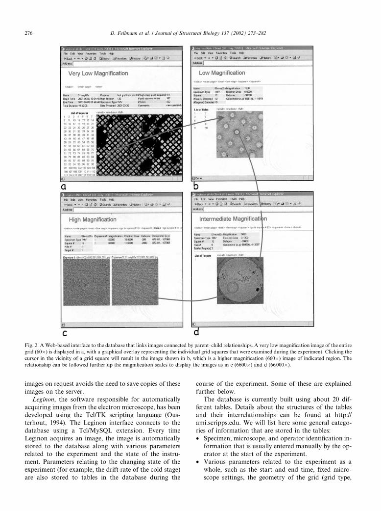
Fig. 5. A map of the entire grid indicating where data were acquired from the grid. Red circles: grid squares where excellent filaments suitable for
inclusion into a final 3D map were found. Yellow circles: squares with filaments that contained a strong 11.5 A layer line. Purple circles: squares that
contained filaments. Blue circles: squares that contained ice of suitable thickness. White crosses: squares that were examined at 660� but were foundnot to contain suitable ice.
280 D. Fellmann et al. / Journal of Structural Biology 137 (2002) 273–282

tion, individual filaments are extracted, subjected tohelical analysis (Carragher et al., 1996), and averagedtogether to form a three-dimensional electron-densitymap. During this process the quality of the images isassessed using a variety of criteria. For example, thepower spectra of the individual extracted filaments areanalyzed. As TMV is an ordered helical specimen itspower spectrum exhibits characteristic layer lines atwell-defined spacings in reciprocal space. The presenceof a layer line at a spacing of 11.5A is used as one testfor accepting or rejecting a filament for further pro-cessing and analysis. Similar criteria are used at varioussubsequent steps during the processing in order to filterout filaments that are not considered of high enoughquality to contribute to the final average 3D map. Theend result is that nearly 90% of the originally selectedfilaments are rejected and only a small number con-tribute to the final map. If we could ascertain the com-mon identifying characteristics of this small number ofexcellent filaments, we might be able to use this infor-mation to improve the overall yield and efficiency of theexperiment. This is exactly the kind of question that canbe readily answered by a query to the database. Forexample, we can check whether the excellent filamentsall originate from the same area of the grid. The resultsof such a query are illustrated in Fig. 5 for one particularexperiment. The results show that in this instance theexcellent filaments are distributed across the grid and arenot confined to any particular area. Data of this sortextracted for a large number and variety of specimenswill be used to build up statistical evidence to help directdata collection protocols.
4. Discussion
We have been using the database described above for1 year. We have collected over 50 000 images duringapproximately 50 experimental sessions. Our experiencewith this database has convinced us that the many ad-vantages it offers make it a critical part of our auto-mated system for data acquisition and analysis. It is vitalfor keeping track of the very large quantities of datacollected and analyzed and essential for evaluating theutility of methods and algorithms used in the data col-lection. As we have gained experience with the databasewe have also expanded and modified the tables to ac-commodate additional relationships and parameters.These changes have always been incorporated in such away that the database remains stable and compatibilityis maintained with older data sets.We foresee that in the future the database will be
required to store on the order of millions of images andpredict that it will be readily scalable to these muchlarger data sets. MySq1 provides a data managementsystem that is quite capable of dealing with searches
through tables of this size. A potential issue is, however,the disk capacity that would be required to store theimages. To address this problem we have integratedthe database with a data management facility (DMF).The DMF is supported by a robotic tape manager thatprovides an essentially infinite storage system. A Web-based user interface allows users of the database to ar-chive or restore entire data sets to the DMF. Thedatabase keeps track of the archive status and handlesrestores so that data need not necessarily be restored tothe original location.We have also begun to use the database in order to
track the relationships between the quality ofhigh magnification images which contribute to thethree-dimensional map and the imaging parameters usedto acquire these images. We believe that there is greatpotential for being able to mine the information in thedatabase for these kinds of relationships. Ultimately wehope that this analysis will point to directions to be takenduring the imaging process that will lead to animprovement in both the efficiency and the quality of theacquired data. This will be one of our primary goalsover the next year.
Acknowledgments
This material is based upon work supported by theNational Science Foundation (Award No. DBI-9904547and DBI-9730056) and the National Institutes of Health(Award No. GM-61939).
References
Baker, T.S., Henderson, R., 2002. Electron cryomicroscopy. Int.
Tables Crystallogr., Volume F.
Birney, E., Bateman, A., Clamp, M.E., Hubbard, T.J., 2001. Mining
the draft human genome. Nature 409, 827–828.
Carazo, J.M., Stelzer, E.H.K., 1999. The bioimage database project:
organizing multidimensional biological images in an object-rela-
tional database. J. Struct. Biol. 125, 97–102.
Carragher, B., Fellmann, D., Kisseberth, N., Milligan, R.A., Potter,
C.S., Pulokas, J., Zhu, Y., 2001. Automation for Cryo-TEM: from
specimen grid to 3D map. Microsc. Microanal. 7, 970–971.
Carragher, B., Kisseberth, N., Kriegman, D., Milligan, R.A., Potter,
C.S., Pulokas, J., Reilein, A., 2000. Leginon: an automated system
for acquistion of images from vitreous ice specimens. J. Struct.
Biol. 132, 33–45.
Carragher, B., Whittaker, M., Milligan, R.A., 1996. Helical processing
using PHOELIX. J. Struct. Biol. 116, 107–112.
Chiu, W., McGough, A., Sherman, M., Schmid, M., 1999. High-
resolution electron cryomicroscopy of macromolecular assemblies.
Trends Cell Biol. 9, 154–159.
Fellmann, D., Carragher, B., Potter, C.S., Pulokas, J., 2001. Appli-
cation of an SQL database for automated image acquisition and
analysis for cryoEM. Microsc. Microanal. 7, 984–985.
Gabashvili, I., Agrawal, R., Spahn, C., Grasucci, R., Svergun, D.,
Frank, J., 2000. Solution structure of the E. coli 70S ribosome at
11.5 A resolution. Cell 100, 537–549.
D. Fellmann et al. / Journal of Structural Biology 137 (2002) 273–282 281
Henderson, R., 1995. The potential and limitations of neutrons,
electrons, and X-rays for atomic resolution microscopy of un-
stained biological macromolecules. Q. Rev. Biophys. 28, 171–193.
Lindek, S., Fritsch, R., Machtynger, J., Alarcon, P.A.D., Chagoyen,
M., 1999. Design and realization of an on-line database for
multidimensional microscopic images of biological specimens. J.
Struct. Biol. 125, 103–111.
Matadeen, R., Patwardhan, A., Gowen, B., Orlova, E., Pape, T., Cuff,
M., Mueller, F., Brimacombe, R., Heel, M.V., 1999. The Escher-
ichia coli large ribosomal subunit at 7.5 A resolution. Structure 7,
1575–1583.
Metoz, F., Sherman, M.B., Schmid, M.F., 2001. Adopting a database
as a solution to managing electron image data. J. Struct. Biol. 133,
170–175.
Ousterhout, J.K., 1994. Tcl and the Tk Toolkit. Addison-Wesley,
Reading, MA.
Potter, C.S., Chu, H., Frey, B., Green, C., Kisseberth, N., Madden,
T.J., Miller, K.L., Nahrstedt, K., Pulokas, J., Reilein, A., Tcheng,
D., Weber, D., Carragher, B., 1999. Leginon: a system for fully
automated acquisition of 1000 micrographs a day. Ultramicros-
copy 77, 153–161.
Ravantti, J.J., Bamford, D.H., 1999. A data mining approach for
analyzing density maps representing macromolecular structures. J.
Struct. Biol. 125, 216–222.
Whittaker, M., Carragher, B.O., Milligan, R., 1995. PHOELIX: a
package for semi-automated helical reconstruction. Ultramicros-
copy 58, 245–259.
Zhu, Y., Carragher, B., Kriegman, D., Potter, C.S., 2001. Automated
identification of filaments in cryo-electron microscopy images. J.
Struct. Biol. 135, 302–312.
282 D. Fellmann et al. / Journal of Structural Biology 137 (2002) 273–282
Related Documents