350 Philips tech. Rev. 40, 350-357,1982, No. 11/12 A refrigerator-freezer with heat pipe G. A. A. Asselman and A. J. van Mensvoort Until recently, combined refrigerator-freezers with the jour-star' rating have required two separate refrigeration circuits each with its own compressor, for optimum operation. The authors have succeeded in making one of the two compressors unnecessary by including a heat pipe that transfers heat from the refrigerator compartment to the refrigeration circuit of the freezer compartment. The problem of temperature control in the refrigerator compart- ment has been solved by using an adsorbant in the heat pipe, combined if necessary with an inert buffer gas. Introduetion ISO standards specify that a combined domestic refrigerator-freezer with a 'three-star' rating should be able to maintain a temperature lower than -18 oe in the freezer compartment. At the same time the tem- perature in the refrigerator compartment should remainbetween 0 and 5 oe. If the refrigerator-freezer has four stars, this means that food can be deep- frozen in the freezer compartment. The refrigeration circuit that extracts heat from the freezer compart- ment, and is normally controlled by a thermostatic 'on/oir' switch, must then be continuously switched on. During deep-freezing, the temperature in the refrigerator compartment must also remain between 0 and 5°C. Until recently it has only been possible to meet these conditions by providing separate refrigeration circuits for the refrigerator compartment and the freezer com- partment, each circuit with its own compressor and its own temperature control; seefig. la and b. Refrigera- tor-freezers do exist with one refrigeration circuit containing two evaporators in cascade, but here only the temperature. in the refrigerator compartment is controlled; see fig. Ic. Deep-freezing is not possible with this arrangement, since the temperature in the refrigerator compartment would become too low with the refrigeration circuit in continuous operation. Since the temperature in the freezer compartment is not controlled, the temperature in this compartment is usually much lower than necessary. In principle, it is Ir G. A. A. Asselman is with Philips Research Laboratories, Eind- hoven; A. J. van Mensvoort, formerly with these laboratories, is now with the Philips Plastics and Metalware Factory, Eindhoven. also possible to have two evaporators in parallel in a single refrigeration circuit: the flow of the refrigerant must then be separately controlled for each evapora- tor; see fig. Id. However, this requires the use of elec- tromechanically operated valves, and these make the system less reliable and relatively expensive. We have found a better solution to the problem by using the principle of the heat pipe [11[21.There isjust one single-compressor refrigeration circuit (called the primary refrigeration circuit); see fig. le. A tempera- ture sensor in the freezer compartment switches the compressor on and oir. The heat pipe has the task of transferring heat from the refrigerator compartment to the evaporator EF of the primary circuit. A heat pipe is able to transfer heat because a liquid evaporates in one part of the pipe and condenses in another. In most heat pipes the condensed vapour is returned by means ofa 'wick', which is a porous layer (usually of gauze) located close to the outer wallof the pipe. In the application described here the condensed liquid is returned by gravity. The part ER where the evapora- tion takes place is situated at the bottom of the heat pipe, in the refrigerator compartment. The part CR where the condensation takes place is situated at the upper end of the heat pipe, at the place where it is in contact with the primary evaporator EF. The working fluid in the heat pipe is the same as that in the primary refrigeration circuit, i.e. CChF2 ('Freon 12'). In theory our method gives a lower efficiency (the ratio of the heat to be removed to the energy used in removing it) than if a second compressor were to be

Welcome message from author
This document is posted to help you gain knowledge. Please leave a comment to let me know what you think about it! Share it to your friends and learn new things together.
Transcript
350 Philips tech. Rev. 40, 350-357,1982, No. 11/12
A refrigerator-freezer with heat pipe
G. A. A. Asselman and A. J. van Mensvoort
Until recently, combined refrigerator-freezers with the jour-star' rating have required twoseparate refrigeration circuits each with its own compressor, for optimum operation. Theauthors have succeeded in making one of the two compressors unnecessary by including aheat pipe that transfers heat from the refrigerator compartment to the refrigeration circuit ofthe freezer compartment. The problem of temperature control in the refrigerator compart-ment has been solved by using an adsorbant in the heat pipe, combined if necessary with aninert buffer gas.
Introduetion
ISO standards specify that a combined domesticrefrigerator-freezer with a 'three-star' rating shouldbe able to maintain a temperature lower than -18 oein the freezer compartment. At the same time the tem-perature in the refrigerator compartment shouldremainbetween 0 and 5 oe. If the refrigerator-freezerhas four stars, this means that food can be deep-frozen in the freezer compartment. The refrigerationcircuit that extracts heat from the freezer compart-ment, and is normally controlled by a thermostatic'on/oir' switch, must then be continuously switchedon. During deep-freezing, the temperature in therefrigerator compartment must also remain between 0and 5°C.Until recently it has only been possible to meet these
conditions by providing separate refrigeration circuitsfor the refrigerator compartment and the freezer com-partment, each circuit with its own compressor and itsown temperature control; seefig. la and b. Refrigera-tor-freezers do exist with one refrigeration circuitcontaining two evaporators in cascade, but here onlythe temperature. in the refrigerator compartment iscontrolled; see fig. Ic. Deep-freezing is not possiblewith this arrangement, since the temperature in therefrigerator compartment would become too low withthe refrigeration circuit in continuous operation. Sincethe temperature in the freezer compartment is notcontrolled, the temperature in this compartment isusually much lower than necessary. In principle, it is
Ir G. A. A. Asselman is with Philips Research Laboratories, Eind-hoven; A. J. van Mensvoort, formerly with these laboratories, isnow with the Philips Plastics and Metalware Factory, Eindhoven.
also possible to have two evaporators in parallel in asingle refrigeration circuit: the flow of the refrigerantmust then be separately controlled for each evapora-tor; see fig. Id. However, this requires the use of elec-tromechanically operated valves, and these make thesystem less reliable and relatively expensive.We have found a better solution to the problem by
using the principle of the heat pipe [11[21.There is justone single-compressor refrigeration circuit (called theprimary refrigeration circuit); see fig. le. A tempera-ture sensor in the freezer compartment switches thecompressor on and oir. The heat pipe has the task oftransferring heat from the refrigerator compartmentto the evaporator EF of the primary circuit. A heatpipe is able to transfer heat because a liquid evaporatesin one part of the pipe and condenses in another. Inmost heat pipes the condensed vapour is returned bymeans ofa 'wick', which is a porous layer (usually ofgauze) located close to the outer wallof the pipe. Inthe application described here the condensed liquid isreturned by gravity. The part ER where the evapora-tion takes place is situated at the bottom of the heatpipe, in the refrigerator compartment. The part CRwhere the condensation takes place is situated at theupper end of the heat pipe, at the place where it isin contact with the primary evaporator EF. Theworking fluid in the heat pipe is the same as thatin the primary refrigeration circuit, i.e. CChF2('Freon 12').In theory our method gives a lower efficiency (the
ratio of the heat to be removed to the energy used inremoving it) than if a second compressor were to be
Philips tech. Rev. 40, No. 11/12 REFRIGERATOR-FREEZER 351
used, since the theoretical maximum efficiency, theCarnot efficiency, is inversely proportional to the tem-perature difference through which the heat must betransferred. Since the heat to be extracted from therefrigerator compartment is brought to the tempera-ture level of the primaryevaporator Ep, this tempera-ture difference is greater in our case. This undesirable
sorbant in the buffer space, the quantity of inert gas inthe heat pipe is varied, since the adsorbant - which isselective - takes up inert gas but not the refrigerant.In this way it is possible to control the effective area ofthe condenser and hence the heat transfer in the heatpipe. In the second system no inert gas is used, and theheat pipe only contains the refrigerant. The amount
g
f.
R
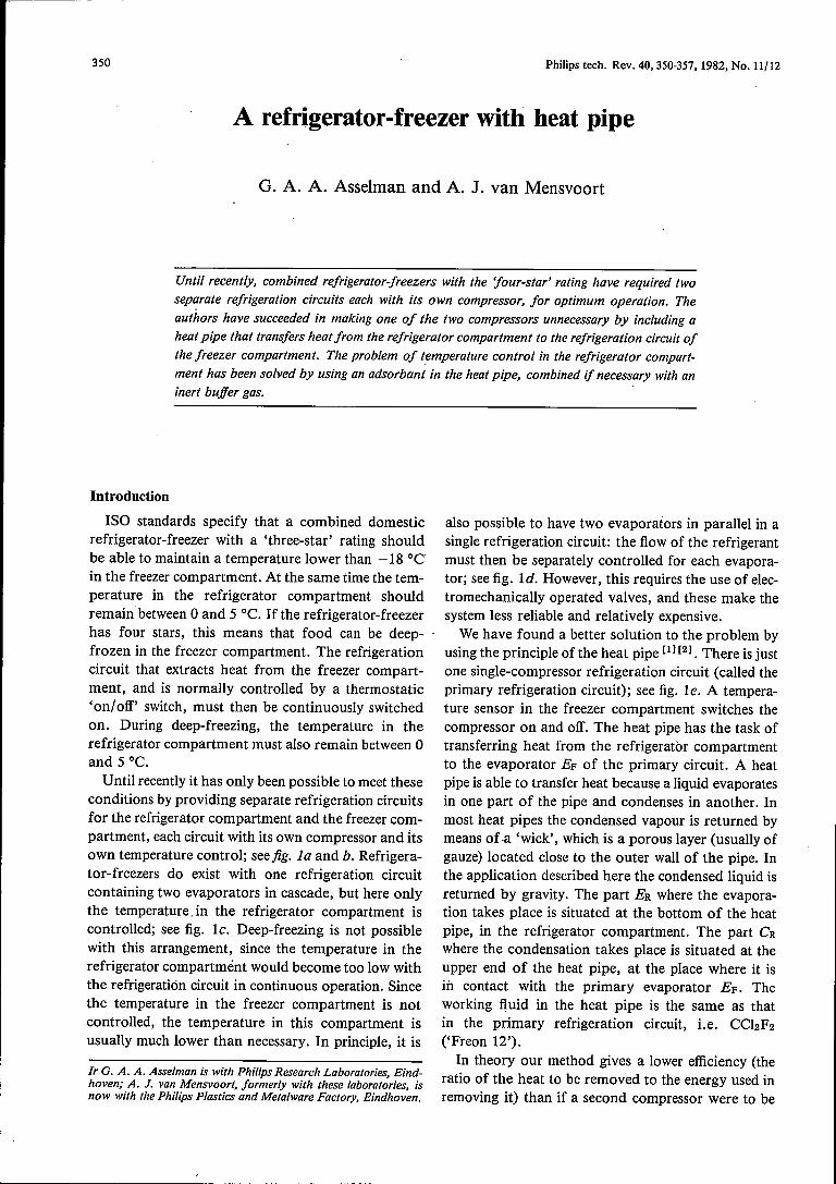
Fig. 1.a) The conventional refrigeration circuit for domestic refrigerators. Cp compressor, C con-denser, E evaporator, Re capillary restriction, T temperature sensor. The refrigerant, usually acompound of fluorine and carbon ('Freon'), evaporates in E; the vapour is compressed by thecompressor and condenses in C; the pressure of the condensate is reduced in Re; the fluid finallyenters the evaporator. The temperature sensor switches the compressor motor on and off asrequired. b) Combination of refrigerator compartment R and freezer compartment F. Each hasits own refrigeration circuit. ER and EF evaporators, CRand CF condensers. c) Combined systemusing a single refrigeration circuit with one condenser C and two evaporators ER and EF incascade. The temperature is measured in R, but not in F. In this system the temperature in Fistherefore usually lower than necessary and deep-freezing is also not possible. d) Refrigerator-freezer with one refrigeration circuit with two evaporators ER and EF in parallel. The tempera-tures in both F and R are measured. The flow .of refrigerant in the two evaporators is controlledby means of two electromechanical valves. e) Refrigerator-freezer with one refrigeration circuit(the primary refrigeration circuit) with compressor. The heat from R is conducted to the evapora-tor EF of the primary circuit by a heat pipe with evaporator ER and condenser CR.
effect is more than compensated, however, because asingle compressor (of greater capacity) has a higherefficiency than two separate compressors. In practice,therefore, a refrigerator-freezer with our system usesthe same amount of energy - or a little less - than asystem with two compressors. The cost of materials isalso lower with only one compressor.
One problem is the control of the temperature inthe refrigerator compartment R. Electromechanicalvalves cannot be used, since they are rather expensiveand insufficiently reliable. The two systems that weshall now describe ultimately proved to be the mostuseful. The first system, discussed earlier in this jour-nal [2], uses a quantity of inert gas, N2 or C02, con-tained in a buffer space connected with the heat pipe.By controlling the temperature of a quantity of ad-
of active refrigerant is controlled by adsorbing someof it in a different type of adsorbant. Here again, theheat transfer is controlled by varying the temperatureof the adsorbant. If a large amount of refrigerant isadsorbed, the remainder cannot reach the bottom ofthe evaporator because it has completely evaporatedhalf-way down. The evaporator then only operatesover part of its surface.In the following we shall first discuss the operation
of the heat pipe in this application. We shall then dealwith the two methods of controlling the temperaturein the refrigerator compartment.
[1] G. A. A. Asselman and D. B. Green, Heat Pipes, I.Operationand characteristics, Philips tech. Rev. 33, 104-113, 1973.
[2] G. A. A. Asselman and D. B. Green, Heat Pipes, Il. Applica-tions, Philips tech. Rev. 33, 138-148, 1973.

352 G. A. A. ASSELMAN and A. J. VAN MENSVOORT Philips tech. Rev. 40, No. 11/12
The heat pipe
The heat pipe without the control system is shownin the diagram of fig. 2. The evaporator ER is at thebottom and the condenser CR is at the top. The con-denser is in contact with the evaporator EF of theprimary refrigeration circuit that cools the freezercompartment. The refrigerant condenses in CR and isreturned by gravity to the evaporator, so that the heatpipe does not require a wick, as mentioned earlier.
The actual appearance of the heat pipe is shown infig. 3. Since the heat-transfer coefficient for the transi-tion from the evaporator to the air in the refrigeratorcompartment is relatively small, the evaporator is partof the large evaporator plate EP, which is attached tothe rear wall of this compartment.
The heat pipe is a means of transferring large quan-tities of heat across a small temperature difference.The heat pipe in this application, with an inside diam-eter of 6 mm and a length of nearly 3 m, can transferup to 70 W with a temperature difference of no morethan 12 DC between condenser and evaporator. If thesame amount of power was transferred by a solidcopper rod of these dimensions the temperature dif-ference between the two ends would have to be about9000 oe.
A heat-transport capability of 70 W is amply suffi-cient. For a refrigerator compartment of volume160 litres - the volume for which our system was
EF
) I:~~,0l'ó~ Wb
~
to "" ~.t"0e
It0
~ .011&'0 ° 0
) 00
'"~ Oot te t '"0."
e m
).)..:).\..;,_
Fig. 2. The heat pipe without control system, schematic. Ep evapor-ator of the primary refrigerating system for the freezer compart-ment. CR condenser of the heat pipe. ER evaporator of the heatpipe. Q heat flow through the heat pipe, from the refrigerator com-partment to the primary evaporator.
!
EP
Fig. 3. Construction of the heat pipe. EP evaporator plate, incor-porating the evaporator ER. The pipe is nearly 3 m long and has aninside diameter of 6 mm. See caption to fig. 2.
designed - about 1 W of refrigeration capacity isrequired per degree of temperature difference betweenthe ambient temperature and the temperature insidethe refrigerator compartment. For a maximum am-bient temperature of 32 DC and a temperature of 5 DCin the refrigerator compartment, the heat pipe there-fore has to provide 27 W of heat-transport capability.There is thus a sufficient surplus of refrigerationcapacity to compensate for losses when the door isopened, and to permit the required temperature to bereached within a reasonable time after switching on.
The limits to the heat-transport capability of a heatpipe are connected with floweffects and the quantityof refrigerant in the pipe. This is illustrated in fig. 4,which gives the results of a number of measurementson the heat pipe in fig. 3. The maximum heat-trans-port capability Qmax was measured for different quan-tities MF of the refrigerant. It is found that the heat-transport capability is limited by three distinct effects.With normal steady-state flow in the pipe, a closed-loop integral for the pressure differences must have avalue of zero. Neglecting the pressure differences inthe radial direction, we find that the closed-loop inte-gral over the length I of the pipe, inclined at an anglea, is given by the expression
I x=[ x=O
gsinaf (Jxdx+ f dpL + f dpv = 0, (1)o x=O x=1
where g is the acceleration due to gravity, ex thedensity of the liquid, PL the pressure in the liquid, p»

Philips tech. Rev. 40, No. 11/12 REFRIGERATOR-FREEZER 353
the vapour pressure and x the position in the pipe,with x = 0 for the condenser end. If equation (1) can-not be satisfied, because there is too little fluid present,an equilibrium arises for part of the pipe: the liquiddoes not reach the bottom end of the evaporator. Thecapacity of the evaporator decreases, and so thereforedoes Qmax, as shown by curve 1 in fig. 4.If, on the other hand, there is too much refrigerant
in the pipe, then again no steady-state equilibrium asgiven by (1) is reached: the level of the liquid is raisédby the vapour bubbles. The condenser becomes ob-structed by the liquid and the heat-transport capabil-ity again decreases: curve 3. The curve is shown as adashed line because relatively few measurements werecarried out in this region, which is of lesser interest.
70W
60Qmax
with the production of waves in the sea by the windblowing over the water [31.
The region in which the heat pipe can be used, andin which the steady-state equilibrium of (1) is present,lies between the MF-axis and the curves 1, 2 and 3 infig. 4. At a given value of MF, the values for theinstantaneous heat transfer lie on a line - for examplethe chain-dotted line in the figure - between theMF-axis and one of the limiting curves. The operatingpoint depends on the temperature difference betweenthe evaporator and the condenser. By using a smallvariable filling (area under curve 1), it is possible tovary Qmax and hence control the temperature of therefrigerator compartment. We shall return to this inmore detail towards the end of this article.
20 80g60-MF
Fig. 4. The region in which the heat pipe can be used. The maximum heat-transport capabilityQmax is plotted as a function of the filling Mp of the heat pipe in fig. 3, as the result of a number ofmeasurements. Curve 1 is the limit when too little Freon is present: the liquid does not reach thebottom of the pipe. Curve 3 (shown dashed because not many measurements were made in thisless-interesting region) is the limit when there is too much Freon in the pipe: the liquid level israised by the vapour bubbles and the condenser becomes obstructed by the liquid. Line 2 is thelimit when the vapour velocity is so high that liquid droplets are carried along with the vapour.This effect occurs if Weber's number exceeds a critical value. The figure in the middle represents anormally operating heat pipe; Ilength of heat pipe, a angle of inclination of the heat pipe, x co-ordinate of position. The diagrams by curves 1, 2 and 3 illustrate the flow pattern at the appro-priate limits. The chain-dotted line indicates one of the possible operating characteristics of theheat pipe.
Line 2, parallel to the MF-axis, corresponds to athird deviation from the steady-state equilibrium of(1). If a large amount of heat must be transferred,liquid is pulled along by the fast-moving vapour. This'entrainment' effect, which does not depend on theamount of liquid in the pipe, is characterized byWeber's number:
I) v2 IWb= _",x__y
where v is the axial velocity of the vapour and y is thesurface tension of the liquid. The effect is comparable
40
(2)
Controlling the temperature in the refrigerator com-partment
Control with an inert buffer gas
One of the ways in which the heat flow through theheat pipe can be varied is shown in jig. 5. Above theactual heat pipe there is a space filled with inert buffergas. The quantity of buffer gas determines the effectivearea of the condenser CR. The vapour flowing in theheat pipe sweeps along any buffer gas that may be
[3J See § 268 in H. Lamb, Hydrodynamics, Dover Publications,New York 1945.

354 G. A. A. ASSELMAN and A. J. VAN MENSVOORT Philips tech. Rev. 40, No. 11/12
present. This gives rise to an interface S, with thebuffer gas and superheated Freon vapour above it.The pressure above the interface is equal to the sum ofthe pressure of the buffer gas pg and the saturatedvapour pressure Ptp of Freon at the temperature tp ofthe primary circuit. The pressure below the interfaceis equal to the saturated vapour pressure Pte of Freonat the temperature te of the evaporator. Since we areconsidering a steady-state situation, we have equi-librium, so that:
-5.y CR
:iill.
;. J.)ER te
g Q
Fig. S. Principle of heat-transfer control by means of an inert gas.Variation of the effective volume of inert gas changes the effectivearea of the condenser CR. S interface between Freon at thesaturated vapour pressure at the temperature te of the evaporatorand a mixture of inert gas with Freon at the saturated vapour pres-sure at the temperature tp of the primary circuit. Other symbols areas explained in the caption of fig. 2. a) Condenser fully operational.b) Condenser only partly operational.
The way in which the quantity of buffer gas can bevaried can be seen from jig. 6. The temperature ts: inthe refrigerator compartment R is measured by meansof the temperature sensor T. The current through aheater element in the space with the adsorbent materialis switched on and off by the control unit CU, depend-ing on the temperature measured. When the adsorbantis heated, buffer gas is released. The interface S in thecondenser (see fig. 5) is then displaced downwards andthe quantity of heat removed from the refrigeratorcompartment R decreases. As a result the temperaturetR increases. The current is then switched off by CUand buffer gas is again adsorbed. Fig. 7 shows whatthe various parts of the system of fig. 6 look like inpractice.
Suitable buffer gases include nitrogen and carbondioxide. The adsorbant chosen is a zeolite of the typeMS4A ('4Á molecular sieve'). This type of zeolite haspores of 0.40 nm diameter and is thus capable of ad-
(3)
sorbing C02 molecules (0.330 nm diameter) or N2molecules (0.315 nm diameter). The larger CChF2molecules cannot be absorbed, however. After trialswith both types of buffer gas, we decided to use C02,largely because the same weight of adsorbant can ad-sorb ten times as much C02 as N2. Furthermore, thecurve of the gas pressure as a function of the tempera-ture of the adsorbant is steeper for C02 than forN2, which means that the control responds morerapidly. Fig. 8 gives the adsorption curves for thecombination MS4A/C02, with the temperature tA ofthe adsorbant as a parameter. It can be seen that theadsorbant must be heated to between 125 and 150°Cto produce sufficient desorption of buffer gas.
H is very important to fill the buffer space with theoptimum quantity of C02. This can be determined asfollows. The maximum volume of C02 required isequal to that of the buffer space plus that of the con-denser, and is reached when the refrigerating action isstopped and no further heat can be transferred by theheat pipe - for example if the refrigerator compart-ment has to be cleaned. In such a situation the highest
T
Cp
Fig. 6. Design of the temperature-control system with a buffer gas.Ttemperature sensor. A adsorbant, which can be heated by a heaterelement. The current through the element is switched on and off bythe control unit CU, depending on the temperature measurementby T. Other symbols are as in fig. I.

Philips tech. Rev. 40, No. 11/12 REFRIGERATOR-FREEZER 355
C02 pressure required is reached when the primaryrefrigeration circuit is permanently switched on('deep-freeze' setting) at a maximum ambient tem-perature of 32 DC (as quoted in the ISO standard). Inthis extreme case the primary evaporator, and there-fore the condenser of the heat pipe as well, reach atemperature tp = - 32 DC, and the evaporator of theheat pipe is then at a temperature equal to the ambienttemperature: te = 32 DC. By employing equation(3) and tables for the saturation vapour pressure ofCCbF2, we find that the pressure of the buffer gas ispg =P32 - P-32 = 7.84 - 0.92 = 6.92 bars. At thispressure the optimum quantity of C02 is 4.2 g for thevolume in our system. Curve 1 infig. 9 gives the sameoptimum value as the result of a number of measure-ments. The temperature tv: of the refrigerator com-partment was measured under the conditions statedabove while the quantity Mo of the buffer gas wasvaried. At Ma > 4.2 g the temperature is indeed equalto the ambient temperature: the heat pipe is out ofaction. If the quantity of buffer gas is smaller, thetemperature is lower and obviously heat is stillremoved from the refrigerator compartment by theheat pipe. Curve 2 in fig. 9 relates to the measurementmade on a fully operating heat pipe, i.e. with the ad-sorbant at a low temperature, and also at an ambienttemperature of 32 DC. The measurements show thatthe heat-transport capability of the heat pipe with aquantity of 4.2 g of buffer gas is indeed sufficient tomeet the requirement that the temperature in therefrigerator compartment should be between 0 and5 DC at a maximum ambient temperature of 32 DC.
Fig. 7. Photograph of the evaporator plate incorporating theevaporator of the heat pipe. At the upper end the heat exchangerformed by EF and CR can be seen (see fig. 3) and the buffer spacewith adsorbent connected to it. The electronic temperature-controlcircuit is on the left. The temperature sensor, attached to theevaporator plate, is on the right. The potentiometer for setting tothe required temperature in the refrigerator compartment is at thelower end.
We can also calculate the maximum permissiblequantity of Freon. When the. refrigerator-freezercabinet is assembled in the factory and the two refri-
076gig
MA
t
25 50 75100
125
150°C
072
0.08
006 L-::---_J_----'-----L,____J007 G7 70bar
---- PFig. 8. Adsorption curves for CO2 and the adsorbant zeolite MS4A.The quantity MA, in grams of adsorbed CO2 per gram of zeolite, isplotted as a function of the pressure p of the non-adsorbed CO2,
for different adsorbant temperatures t«.
35°C,------------------,
30---/-+-+r 25 " ' 120;75 +
70
5
-5
-7030 35 4.0 4.5 5.0 55g---- MG
Fig. 9. Determining the optimum quantity of CO2 buffer gas in theheat pipe. For two situations the température IR in the refrigeratorcompartment is shown as a function of the quantity Mo of buffergas. Curve 1 relates to the extreme case where the primary refrigera-tion circuit is permanently switched on ('deep-freeze' setting), theambient temperature is 32°C (the maximum value specified by theISO standard) and the adsorbant is heated. It can be seen that witha filling of 4.2 g of CO2 the refrigeration of the refrigerator com-partment can just be switched off (by heating the adsorbant), aswould be necessary for cleaning. Curve 2 relates to maximumoperation of the heat pipe, again at an ambient temperature of32°C. The adsorbant is not heated in this case. It can be seen thatwith a filling of 4.2 g of CO2 the heat-transport capability of theheat pipe is still high enough to meet the requirements that the tem-perature in the refrigerator should be between 0 and 5 oe. Curve 2is not parallel to the Mo-axis because, with a larger C02 filling, arather higher pressure is necessary for the CO2 to be taken up bythe adsorbant. This situation corresponds to a higher evaporatortemperature le and hence to a higher temperature IR.
356 G. A. A. ASSELMAN and A. J. VAN MENSVOORT Philips tech. Rev. 40, No. 11/12
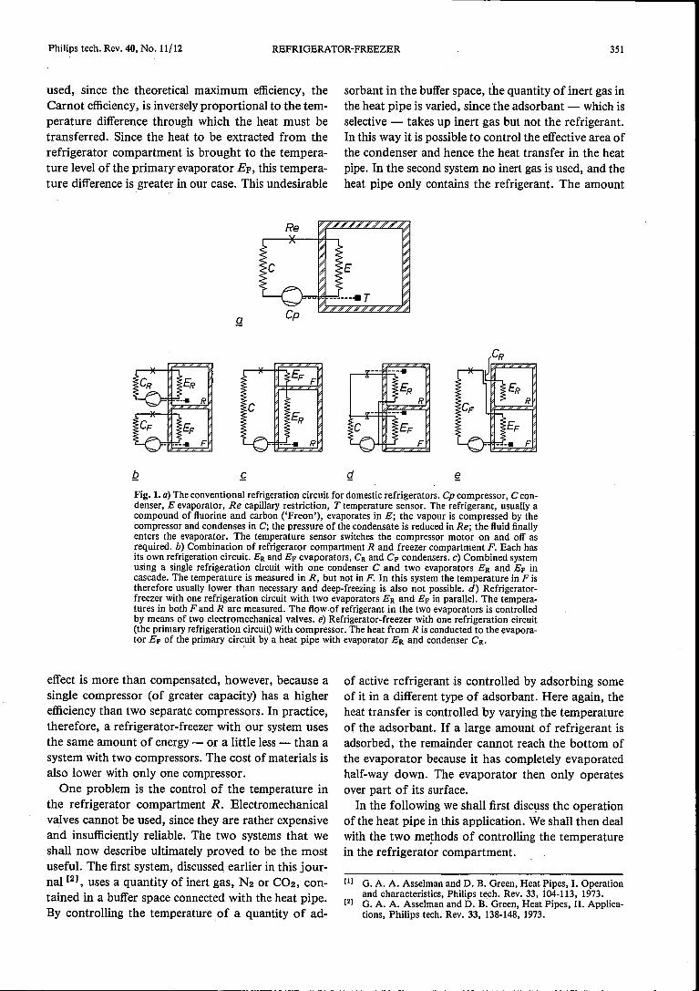
geration systems have been filled, the double walls ofthe cabinet are filled with polyurethane foam. Thismaterial is produced by a chemical reaction in situwhile the entire cabinet is heated to a temperature of75°C in an oven. If liquid Freon was present in theheat pipe at this temperature, the pressure in the heatpipe would rise to the saturated vapour pressure of20.9 bars. For structural reasons, however, the pres-sure in the heat pipe should not exceed 9 bars. Infig. 10 curve 1is a plot of the saturated vapour pres-sure of Freon 12 asa function of temperature. Thepoint P relates to the safety limit: 9 bars at 75°C.
20barI
18 II
P II
t16 I
1114 /
II
12 ////
10 // P,--------r------Q / 2
2
00 10 20 30 40 50 60 70 BO°C-t
Fig. 10. Determining the optimum quantity of Freon in the heatpipe in the system with buffer gas. Curve 1 gives the saturatedvapour pressure p of CChF 2 (Freon 12) as a function of tempera-ture t. At a temperature of 75°C (the temperature reached whenthe walls of the cabinet are being filled with polyurethane foam)the pressure would rise to an excessive level if liquid Freon werepresent. The pressure should then be no higher than 9 bars, how-ever: the point P. Curve 2, relating to the function p/(273 + t) =constant, relates to a situation that is only just safe. At point Q theliquid has then just vaporized during the heating-up period. Thedensity of the saturated vapour at the associated temperature of32°C gives the maximum permissible quantity of Freon (6 grams).The corresponding operating line (the chain-dotted line) in fig. 4indicates that with this filling the heat pipe can operate at maximumheat-transport capability.
Curve 2 gives a plot of the function p/(273 + t) =constant. At the point Q, where curves 1 and 2 inter-sect, the liquid must have just disappeared during theheating-up period. The density of the saturated Freonvapour at the corresponding temperature of 32°C is0.045 g/cms. At temperatures up to 75 oe the buffergas is almost completely taken up by the adsorbant,and therefore in calculating the quantity of Freonvapour we must allow for the entire volume of theheat pipe, including the space for the buffer gas. This
total volume is 133 ern", and with the density quotedabove, it corresponds to a maximum permissiblequantity of Freon of 6 g. This is also nearly equal tothe limit filling at which the heat pipe can just operateat maximum heat-transport capability, as indicatedby the chain-dotted line in the graph of fig. 4. Thequantities of Freon and e02 used for filling the heatpipe must therefore be determined very accurately.
Control without buffer gas
The system shown in fig. 6 can be greatly simplifiedby using an adsorbant capable' of taking up Freon.The inert buffer gas is then no longer necessary. Theheat-transport capability is varied by operating theheat pipe in the region under curve 1 in fig. 4. Theeffectivepart of the evaporator is then varied, and notthe effective part of the condenser, as in the previoussystem. The control action then has to be reversed. Ifthe temperature of the refrigerator compartment rises,the heating of the adsorbant must be switched on; inthe previous system the heating of the adsorbant thenhad to be switched off.
25MA 50
75
100
125
0.1
0.05
0.030.1 0.5 2 3 4 Sbar
-p
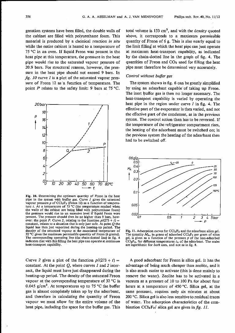
Fig. 11. Adsorption curves for CChF 2 and the adsorbant silica gel.The quantity MA, in grams of adsorbed CCl2F2 per gram of silicagel, is given as a function of the pressure p of the non-adsorbedCChF2, for different temperatures tA of the adsorbant. The scalesare logarithmic for both axes, and not as in fig. 8.
A good adsorbant for Freon is silica gel. It has theadvantage of being much cheaper than zeolite, and itis also much easier to activate (this is done mainly toremove the water). Zeolite has to be activated in avacuum at a pressure of 10 to 100 Pa for about fourhours at a temperature of 450 oe. Silica gel, at thesame pressure, requires only six minutes at about200 oe. Silica gel is also less sensitive to residual tracesof water. The adsorption characteristics of the com-bination CCI2F2/ silica gel are given in fig. 11.

Philips tech. Rev. 40, No. 11/12 REFRIGERATOR-FREEZER 357
Since the refrigerant is mostly adsorbed in the silicagel during the filling of the double walls of the refrige-rator with polyurethane foam, the pressure in the heatpipe is lower. The quantity of Freon is therefore sub-ject to less criticallimits than in the previous system,and this. considerably simplifies manufacture.A disadvantage of the buffer-gas system is that,
when a new refrigerator is put into operation, themixing of C02 and Freon in the heat pipe causes somedelay. It takes some time before the refrigerant andthe buffer gas are separated to give the ideal steady-state situation indicated in fig. 5. This difficulty doesnot occur in the system without buffer gas, and thefull heat-transport capability of the heat pipe isdirectly available.The factory at Cassinetta di Biandromo, Italy - part
of the Philips Major Domestic Appliances Division -has produced 30 prototype refrigerator-freezers,operating with the heat pipe with C02 buffer gas asdescribed here. These prototypes were tested and
operated satisfactorily for a year and met the require-ments of the ISO standards comfortably. In the mean-time some of these refrigerators have been fitted witha heat pipe without buffer gas. These also operatedsatisfactorily, with the advantageous features men-tioned above.
Summary. Until recently refrigerator-freezers with separate tem-perature controls required two distinct refrigeration circuits, eachwith its own compressor, for optimum operation. The use of a heatpipe, which transfers heat from the refrigerator to the refrigerationcircuit of the freezer, makes a second compressor unnecessary. Aheat pipe can transmit a very high heat lIow with a small tempera-ture gradient between condenser and evaporator. The heat-trans-port capability has an upper limit, however, connected with lIoweffects in the pipe and with the quantity of refrigerant. To controlthe temperature in the refrigerator compartment it is necessary tobe able to reduce the heat-transport capability of the heat pipe asrequired. This can be done by limiting the action of the condenseror evaporator. In the first case it is necessary to use an inert buffergas, which can be taken up in an adsorbant (a zeolite). In the secondcase the refrigerant itself is adsorbed in a different type of adsorbant(silica gel).
Related Documents