Nonlinear Dynamics 36: 181–201, 2004. C 2004 Kluwer Academic Publishers. Printed in the Netherlands. A Re-Configurable Test Apparatus for Complex Nonlinear Dynamic Systems J. P. CAFFREY 1 , S. F. MASRI 1,∗ , F. TASBIHGOO 1 , A. W. SMYTH 2 , and A. G. CHASSIAKOS 3 1 Department of Civil Engineering, University of Southern California, Los Angeles, CA 90089, USA; 2 Department of Civil Engineering & Engineering Mechanics, Columbia University, New York, NY 10027, USA; 3 Department of Electrical Engineering, California State University, Long Beach, CA 90840, USA; ∗ Author for correspondence (e-mail: [email protected]; fax: +1-213-740-3984) (Received: 12 December 2003; accepted: 19 January 2004) Abstract. This paper reports the results of an analytical and experimental study to design, analyze, construct, test, and evaluate a re-configurable test-bed to allow the convenient performance of sophisticated experiments in a laboratory setting for investigating a broad category of important nonlinear, time-varying phenomena that are widely encountered in the applied mechanics field. The essential elements of the test apparatus include an electro-dynamic exciter that drives an oscillating mass whose restoring force is easily adjustable from one resembling a linear SDOF mass-spring-damper system with constant coefficients, to one that can represent systems with nonlinear elastic forces, to one that models systems possessing hysteretic properties with precisely- controlled time-varying characteristics. The apparatus design is economical to fabricate, convenient to manipulate, and it provides results that can be accurately replicated under repeated test combinations of system parameters and dynamic loads. The utility of the apparatus to provide an investigational tool for studying the dynamic response of systems with time-varying dry-friction forces that give rise to hysteretic phenomena is demonstrated. Sophisticated on-line system-identification techniques are used to estimate the parameters of reduced-order models that capture the dominant features of the physical model. It is shown that the apparatus under discussion is a useful research tool for investigators conducting studies in physics-based models of generic nonlinear dynamic systems. Key words: Bouc–Wen models, hysteretic systems, nonlinear systems, parameter identification 1. Introduction 1.1. BACKGROUND There is a strong interest in investigating nonlinear systems for analysis of experimental mea- surements and for developing high-fidelity reduced-order nonlinear models for a variety of appli- cations, including control, simulation, and monitoring. One such example that is of considerable interest involves bolted joints whose deformations induce friction forces, hysteretic phenomena, etc. [1]. To develop software simulation packages for reliable emulation of the dynamic response of such complex nonlinear systems, it is important to develop verifiable, physics-based models through care- fully designed and conducted experimental tests. However, there are practical challenges to performing comprehensive experimental investigations. Among the hurdles encountered in performing experi- mental studies, is the time-consuming effort needed to design and deploy the test apparatus, partic- ularly when there is a need to modify the physical parameters to allow comprehensive experimen- tal studies focused on understanding the influence and interaction of various system and excitation parameters.

Welcome message from author
This document is posted to help you gain knowledge. Please leave a comment to let me know what you think about it! Share it to your friends and learn new things together.
Transcript
Nonlinear Dynamics 36: 181–201, 2004.C© 2004 Kluwer Academic Publishers. Printed in the Netherlands.
A Re-Configurable Test Apparatus for Complex Nonlinear DynamicSystems
J. P. CAFFREY1, S. F. MASRI1,∗, F. TASBIHGOO1, A. W. SMYTH2, and A. G. CHASSIAKOS3
1Department of Civil Engineering, University of Southern California, Los Angeles, CA 90089, USA; 2Department of CivilEngineering & Engineering Mechanics, Columbia University, New York, NY 10027, USA; 3Department of ElectricalEngineering, California State University, Long Beach, CA 90840, USA; ∗Author for correspondence(e-mail: [email protected]; fax: +1-213-740-3984)
(Received: 12 December 2003; accepted: 19 January 2004)
Abstract. This paper reports the results of an analytical and experimental study to design, analyze, construct, test, and evaluate are-configurable test-bed to allow the convenient performance of sophisticated experiments in a laboratory setting for investigatinga broad category of important nonlinear, time-varying phenomena that are widely encountered in the applied mechanics field.The essential elements of the test apparatus include an electro-dynamic exciter that drives an oscillating mass whose restoringforce is easily adjustable from one resembling a linear SDOF mass-spring-damper system with constant coefficients, to one thatcan represent systems with nonlinear elastic forces, to one that models systems possessing hysteretic properties with precisely-controlled time-varying characteristics. The apparatus design is economical to fabricate, convenient to manipulate, and it providesresults that can be accurately replicated under repeated test combinations of system parameters and dynamic loads. The utilityof the apparatus to provide an investigational tool for studying the dynamic response of systems with time-varying dry-frictionforces that give rise to hysteretic phenomena is demonstrated. Sophisticated on-line system-identification techniques are usedto estimate the parameters of reduced-order models that capture the dominant features of the physical model. It is shown thatthe apparatus under discussion is a useful research tool for investigators conducting studies in physics-based models of genericnonlinear dynamic systems.
Key words: Bouc–Wen models, hysteretic systems, nonlinear systems, parameter identification
1. Introduction
1.1. BACKGROUND
There is a strong interest in investigating nonlinear systems for analysis of experimental mea-surements and for developing high-fidelity reduced-order nonlinear models for a variety of appli-cations, including control, simulation, and monitoring. One such example that is of considerableinterest involves bolted joints whose deformations induce friction forces, hysteretic phenomena,etc. [1].
To develop software simulation packages for reliable emulation of the dynamic response of suchcomplex nonlinear systems, it is important to develop verifiable, physics-based models through care-fully designed and conducted experimental tests. However, there are practical challenges to performingcomprehensive experimental investigations. Among the hurdles encountered in performing experi-mental studies, is the time-consuming effort needed to design and deploy the test apparatus, partic-ularly when there is a need to modify the physical parameters to allow comprehensive experimen-tal studies focused on understanding the influence and interaction of various system and excitationparameters.
182 J. P. Caffrey et al.
1.2. MOTIVATION
With the above discussion in mind, the purpose of the experimental and analytical investigation underdiscussion is to design, analyze, construct, calibrate, and evaluate a re-configurable test apparatus forstudying generic nonlinear phenomena, widely encountered in the applied mechanics field, such aselastic nonlinearities, nonlinear viscous forces, dry-friction, and time-varying hysteretic phenomena.
1.3. SCOPE
Section 2 of the paper discusses the experimental apparatus’ main components and shows the widelatitude available through it to investigate different classes of nonlinear phenomena under dynamic en-vironments. Section 3 presents some sample measurements corresponding to different nonlinear regimesof time-varying nonlinear phenomena that can be induced by the test apparatus. Section 4 presents non-linear system identification results corresponding to measurements obtained from the apparatus, whenit is configured to investigate the development of reduced-order, low-complexity mathematical modelscorresponding to systems incorporating time-varying hysteretic elements.
2. Description of Re-Configurable Test Apparatus
2.1. MAJOR ELEMENTS
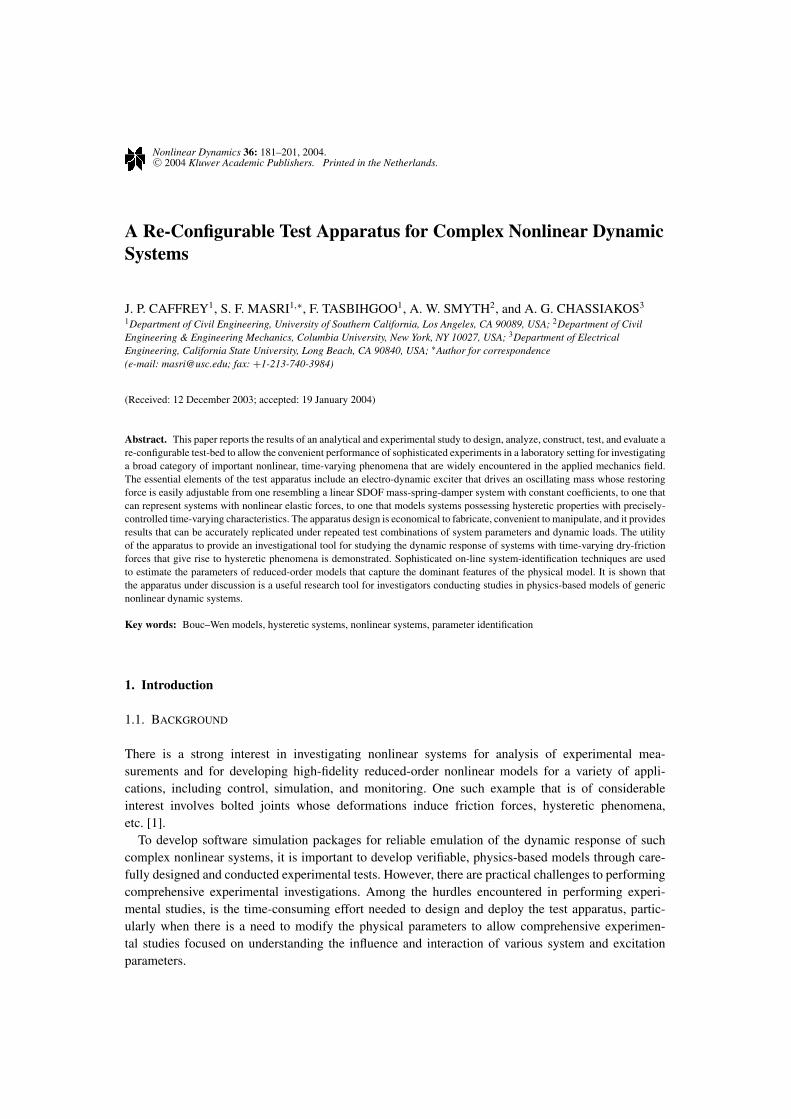
The test apparatus was designed to represent a single-degree-of-freedom (SDOF) nonlinear systemhaving a sliding mass m that is connected by a nonlinear resilient element to a fixed point, while themass is subjected to an external disturbance F(t). A simplified mathematical model of such a systemis depicted in Figure 1. Its main components are the lumped mass m and the nonlinear restoring forceelement r (x, x).
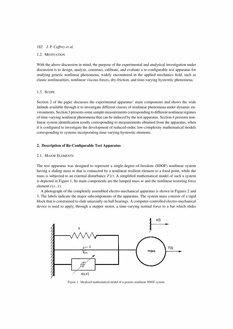
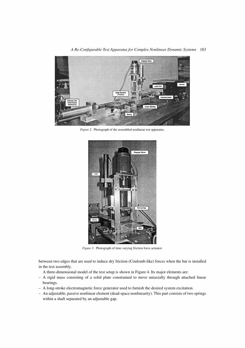
A photograph of the completely assembled electro-mechanical apparatus is shown in Figures 2 and3. The labels indicate the major subcomponents of the apparatus. The system mass consists of a rigidblock that is constrained to slide uniaxially on ball bearings. A computer-controlled electro-mechanicaldevice is used to apply, through a stepper motor, a time-varying normal force to a bar which slides
Figure 1. Idealized mathematical model of a generic nonlinear SDOF system.
A Re-Configurable Test Apparatus for Complex Nonlinear Dynamic Systems 183
Figure 2. Photograph of the assembled nonlinear test apparatus.
Figure 3. Photograph of time-varying friction force actuator.
between two edges that are used to induce dry friction (Coulomb-like) forces when the bar is installedin the test assembly.
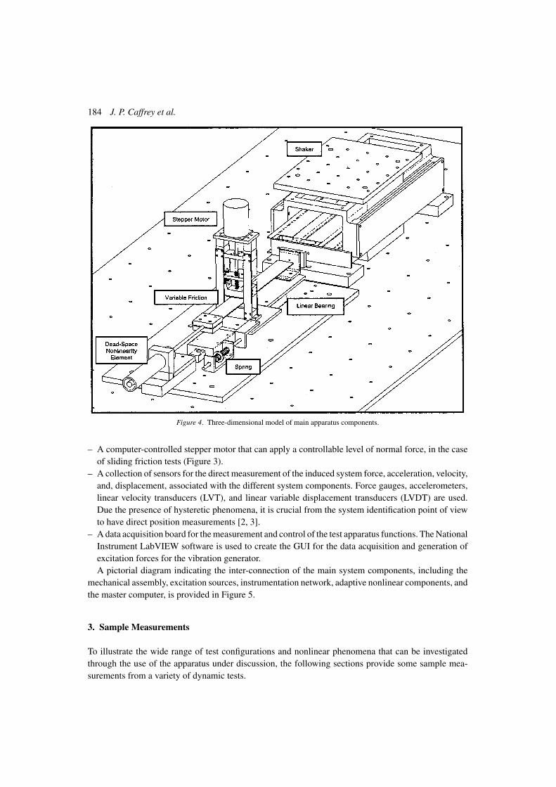
A three-dimensional model of the test setup is shown in Figure 4. Its major elements are:– A rigid mass consisting of a solid plate constrained to move uniaxially through attached linear
bearings.– A long-stroke electromagnetic force generator used to furnish the desired system excitation.– An adjustable, passive nonlinear element (dead-space nonlinearity). This part consists of two springs
within a shaft separated by an adjustable gap.
184 J. P. Caffrey et al.
Figure 4. Three-dimensional model of main apparatus components.
– A computer-controlled stepper motor that can apply a controllable level of normal force, in the caseof sliding friction tests (Figure 3).
– A collection of sensors for the direct measurement of the induced system force, acceleration, velocity,and, displacement, associated with the different system components. Force gauges, accelerometers,linear velocity transducers (LVT), and linear variable displacement transducers (LVDT) are used.Due the presence of hysteretic phenomena, it is crucial from the system identification point of viewto have direct position measurements [2, 3].
– A data acquisition board for the measurement and control of the test apparatus functions. The NationalInstrument LabVIEW software is used to create the GUI for the data acquisition and generation ofexcitation forces for the vibration generator.A pictorial diagram indicating the inter-connection of the main system components, including the
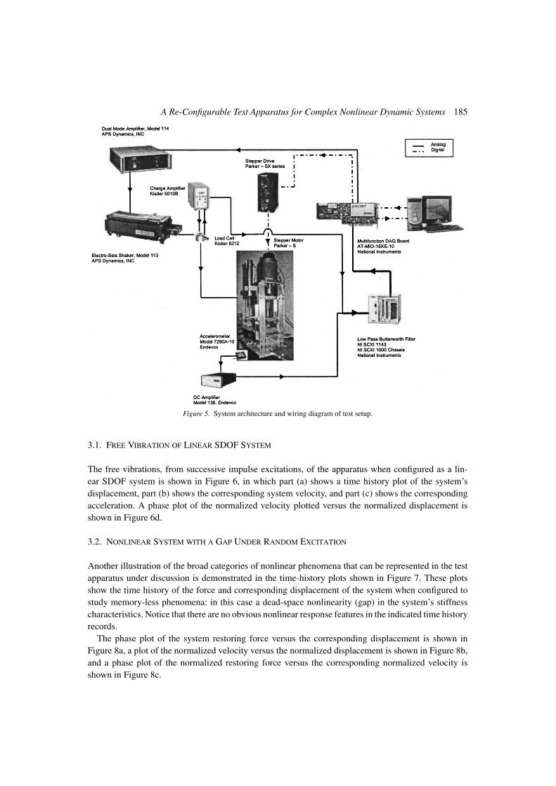
mechanical assembly, excitation sources, instrumentation network, adaptive nonlinear components, andthe master computer, is provided in Figure 5.
3. Sample Measurements
To illustrate the wide range of test configurations and nonlinear phenomena that can be investigatedthrough the use of the apparatus under discussion, the following sections provide some sample mea-surements from a variety of dynamic tests.
A Re-Configurable Test Apparatus for Complex Nonlinear Dynamic Systems 185
Figure 5. System architecture and wiring diagram of test setup.
3.1. FREE VIBRATION OF LINEAR SDOF SYSTEM
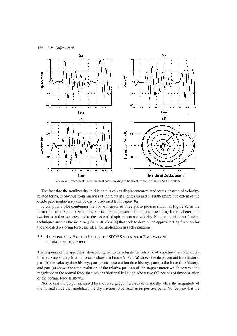
The free vibrations, from successive impulse excitations, of the apparatus when configured as a lin-ear SDOF system is shown in Figure 6, in which part (a) shows a time history plot of the system’sdisplacement, part (b) shows the corresponding system velocity, and part (c) shows the correspondingacceleration. A phase plot of the normalized velocity plotted versus the normalized displacement isshown in Figure 6d.
3.2. NONLINEAR SYSTEM WITH A GAP UNDER RANDOM EXCITATION
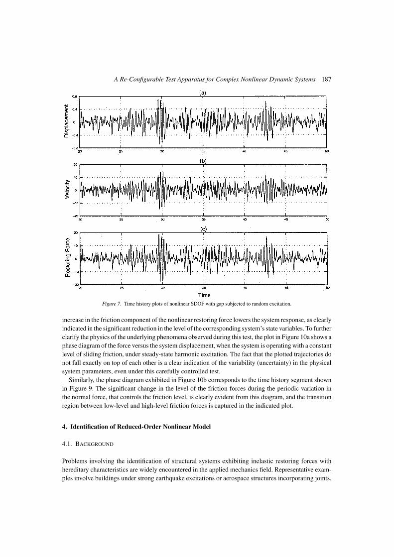
Another illustration of the broad categories of nonlinear phenomena that can be represented in the testapparatus under discussion is demonstrated in the time-history plots shown in Figure 7. These plotsshow the time history of the force and corresponding displacement of the system when configured tostudy memory-less phenomena: in this case a dead-space nonlinearity (gap) in the system’s stiffnesscharacteristics. Notice that there are no obvious nonlinear response features in the indicated time historyrecords.
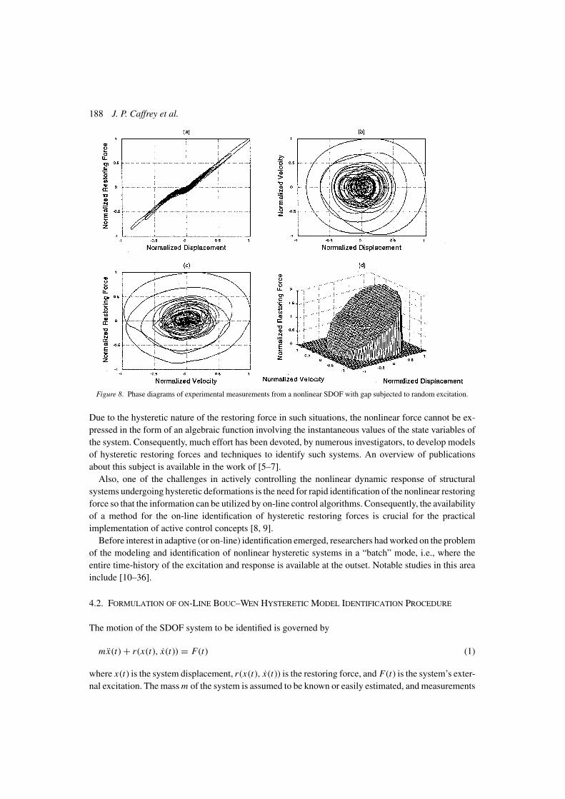
The phase plot of the system restoring force versus the corresponding displacement is shown inFigure 8a, a plot of the normalized velocity versus the normalized displacement is shown in Figure 8b,and a phase plot of the normalized restoring force versus the corresponding normalized velocity isshown in Figure 8c.
186 J. P. Caffrey et al.
Figure 6. Experimental measurement corresponding to transient response of linear SDOF system.
The fact that the nonlinearity in this case involves displacement-related terms, instead of velocity-related terms, is obvious from analysis of the plots in Figures 8a and c. Furthermore, the extent of thedead-space nonlinearity can be easily discerned from Figure 8a.
A compound plot combining the above mentioned three phase plots is shown in Figure 8d in theform of a surface plot in which the vertical axis represents the nonlinear restoring force, whereas thetwo horizontal axes correspond to the system’s displacement and velocity. Nonparametric identificationtechniques such as the Restoring Force Method [4] that seek to develop an approximating function forthe indicated restoring force, are ideal for application in such situations.
3.3. HARMONICALLY EXCITED HYSTERETIC SDOF SYSTEM WITH TIME-VARYING
SLIDING FRICTION FORCE
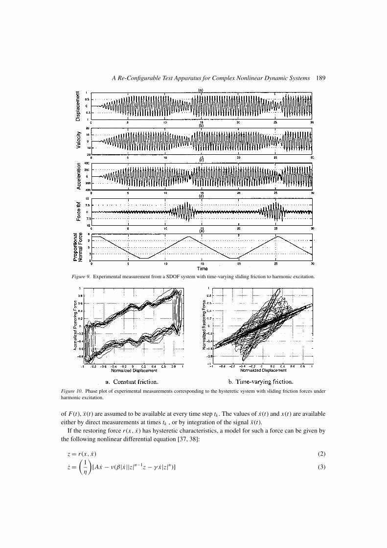
The response of the apparatus when configured to investigate the behavior of a nonlinear system with atime-varying sliding friction force is shown in Figure 9. Part (a) shows the displacement time history;part (b) the velocity time history; part (c) the acceleration time history; part (d) the force time history;and part (e) shows the time-evolution of the relative position of the stepper motor which controls themagnitude of the normal force that induces frictional behavior. About two full periods of time-variationof the normal force is shown.
Notice that the output measured by the force gauge increases dramatically when the magnitude ofthe normal force that modulates the dry friction force reaches its positive peak. Notice also that the
A Re-Configurable Test Apparatus for Complex Nonlinear Dynamic Systems 187
Figure 7. Time history plots of nonlinear SDOF with gap subjected to random excitation.
increase in the friction component of the nonlinear restoring force lowers the system response, as clearlyindicated in the significant reduction in the level of the corresponding system’s state variables. To furtherclarify the physics of the underlying phenomena observed during this test, the plot in Figure 10a shows aphase diagram of the force versus the system displacement, when the system is operating with a constantlevel of sliding friction, under steady-state harmonic excitation. The fact that the plotted trajectories donot fall exactly on top of each other is a clear indication of the variability (uncertainty) in the physicalsystem parameters, even under this carefully controlled test.
Similarly, the phase diagram exhibited in Figure 10b corresponds to the time history segment shownin Figure 9. The significant change in the level of the friction forces during the periodic variation inthe normal force, that controls the friction level, is clearly evident from this diagram, and the transitionregion between low-level and high-level friction forces is captured in the indicated plot.
4. Identification of Reduced-Order Nonlinear Model
4.1. BACKGROUND
Problems involving the identification of structural systems exhibiting inelastic restoring forces withhereditary characteristics are widely encountered in the applied mechanics field. Representative exam-ples involve buildings under strong earthquake excitations or aerospace structures incorporating joints.
188 J. P. Caffrey et al.
Figure 8. Phase diagrams of experimental measurements from a nonlinear SDOF with gap subjected to random excitation.
Due to the hysteretic nature of the restoring force in such situations, the nonlinear force cannot be ex-pressed in the form of an algebraic function involving the instantaneous values of the state variables ofthe system. Consequently, much effort has been devoted, by numerous investigators, to develop modelsof hysteretic restoring forces and techniques to identify such systems. An overview of publicationsabout this subject is available in the work of [5–7].
Also, one of the challenges in actively controlling the nonlinear dynamic response of structuralsystems undergoing hysteretic deformations is the need for rapid identification of the nonlinear restoringforce so that the information can be utilized by on-line control algorithms. Consequently, the availabilityof a method for the on-line identification of hysteretic restoring forces is crucial for the practicalimplementation of active control concepts [8, 9].
Before interest in adaptive (or on-line) identification emerged, researchers had worked on the problemof the modeling and identification of nonlinear hysteretic systems in a “batch” mode, i.e., where theentire time-history of the excitation and response is available at the outset. Notable studies in this areainclude [10–36].
4.2. FORMULATION OF ON-LINE BOUC–WEN HYSTERETIC MODEL IDENTIFICATION PROCEDURE
The motion of the SDOF system to be identified is governed by
mx(t) + r (x(t), x(t)) = F(t) (1)
where x(t) is the system displacement, r (x(t), x(t)) is the restoring force, and F(t) is the system’s exter-nal excitation. The mass m of the system is assumed to be known or easily estimated, and measurements
A Re-Configurable Test Apparatus for Complex Nonlinear Dynamic Systems 189
Figure 9. Experimental measurement from a SDOF system with time-varying sliding friction to harmonic excitation.
Figure 10. Phase plot of experimental measurements corresponding to the hysteretic system with sliding friction forces underharmonic excitation.
of F(t), x(t) are assumed to be available at every time step tk . The values of x(t) and x(t) are availableeither by direct measurements at times tk , or by integration of the signal x(t).
If the restoring force r (x, x) has hysteretic characteristics, a model for such a force can be given bythe following nonlinear differential equation [37, 38]:
z = r (x, x) (2)
z =(
1
η
)[Ax − ν(β|x ||z|n−1z − γ x |z|n)] (3)
190 J. P. Caffrey et al.
Different combinations of the parameters η, A, ν, β, γ , and n will produce smooth hysteretic loopsof various hardening or softening characteristics, with different amplitudes and shapes.
Let F(k) = F(tk); x(k) = x(tk); x(k) = x(tk); x(k) = x(tk), and z(k) = z(tk). The system equationof motion (Equation (1)) is rewritten as:
r (k) = z(k) = F(k) − mx(k) (4)
Hence, the values of z at time tk are available, and the identification problem can be stated as: given themass m, and using the on-line measurements of x, x, x, and F , make on-line estimates of the unknownparameters of the hysteretic model expressed by Equation (3).
4.3. ON-LINE IDENTIFICATION ALGORITHM
The hysteretic model described in Section 4.2, obeys the nonlinear differential equation (3). The modelis parameterized linearly with respect to the coefficients (1/η)A, (1/η)νβ, and (1/η)νγ , but nonlinearlywith respect to the power n. It is, however, desirable to use a linearly parameterized estimator for theon-line estimation of hysteretic behavior, hence the following modification of the model expressed byEquation (3) will be used:
z =(
1
η
) [Ax −
n=N∑n=1
anν(β|x ||z|n−1z − γ x |z|n)
](5)
where the value of coefficient an determines the contribution of power n to the hysteresis, and N is alarge enough integer. For example, if the value of power n in the model (Equation (3)) is n = 3, thenthe coefficients ai in Equation (5) will be: a1 = 0, a2 = 0, a3 = 1.
For applying the on-line Least Squares identification algorithms, the differential equation representinga system should be expressed in the form of a linear Static Parametric Model [39]:
z = θ∗T φ (SPM) (6)
where z is the measurement vector,φ is the signal (or regressor) vector, and θ is the parameter (unknowns)vector. Note, this is a linear combination of nonlinear response variables. In SPM models, there is alinear relation between the parameters and the response, transfer function, and other inputs/outputs ofthe system.1
The parameters of a linear SPM can be identified by using the adaptive Least Squares algorithms[40–42]. Following the work of [39], the modified Least-Squares algorithm with forgetting factor foridentifying θ (t), the estimate of θ∗, is obtained by solving ∇ J (θ ) = 0. The cost function J (θ ) for theRecursive Adaptive Least-Squares algorithm with Forgetting-Factor is defined as:
J (θ ) = 1
2
∫ t
0exp−β(t−τ ) [z(τ ) − θT φ(τ )]2
m2s(τ )
dτ + 1
2exp−βt (θ − θ0)T Q0(θ − θ0) (7)
where, Q0 = QT0 > 0, β ≥ 0, θ0 = θ (0). The recursive Least-Squares Algorithm for continuous-time
is:
θ = Pεφ (8)
1 The parametric models for adaptive identification algorithms are not limited to SPM models [39].

A Re-Configurable Test Apparatus for Complex Nonlinear Dynamic Systems 191
P ={
β P − P φφT
m2s
P, if ‖P(t)‖ ≤ R0
0 otherwise(9)
where, P(0) = P0 = PT0 , ||P0|| ≤ R0, R0 is the upper bound for ||P||, ms is the normalizing signal,
and β ≥ 0 is the forgetting factor [39].For the nonlinear hysteretic system defined by the Bouc-Wen model (Equation (3)), the SPM can be
derived by differentiating Equation (4) with respect to time and redefining the z in sz notation, wheres is the Laplace variable with zero initial condition [39]. The parametric model for Equation (1) thusbecomes:
F = mx + r (x, x) (10)
z = r (x, x) = F − mx (11)
z = r = sr (12)
z = s(F − mx) (13)
sr = s(F − mx) (14)
r =(
1
η
) [Ax −
n=N∑n=1
anν(β|x ||r |n−1r − γ x |r |n)
](15)
s(F − mx) =(
1
η
) [Ax −
n=N∑n=1
anν(β|x ||r |n−1r − γ x |r |n)
](16)
For avoiding the noise caused by differentiator block s in the identification process, both sides of theparametric model in Equation (16) are filtered by a stable filter 1
(s) , where (s) is a Hurwitz polynomial,here (s) is chosen as s + λ and λ > 0.
s
s + λ(F − mx) =
(1
s + λ
){1
η
[Ax −
n=N∑n=1
anν(β|x ||r |n−1r − γ x |r |n)
]}(17)
(s
s + λ(F − mx)
)︸ ︷︷ ︸
z
=
A
η
−νβa1
η
νγ a1
η
...
−νβaN
η
νγ aN
η
T
︸ ︷︷ ︸θ∗T
1
s + λx
1
s + λ|x ||r |1−1
1
s + λx |r |1
...
1
s + λ|x |r |N−1
1
s + λx |r |N
︸ ︷︷ ︸φ
(18)
Equation (18) is the SPM for a nonlinear hysteretic system defined by the Bouc–Wen nonlineardifferential equation.
192 J. P. Caffrey et al.
4.4. ANALYSIS OF SAMPLE TEST RESULTS
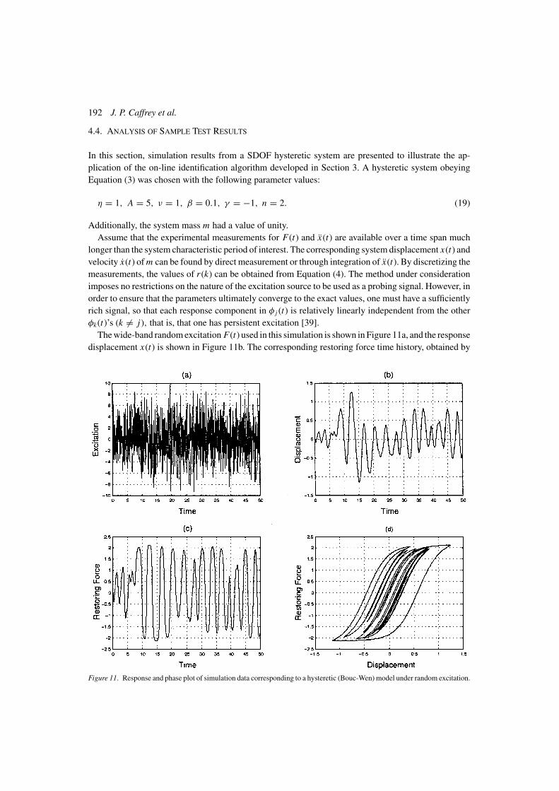
In this section, simulation results from a SDOF hysteretic system are presented to illustrate the ap-plication of the on-line identification algorithm developed in Section 3. A hysteretic system obeyingEquation (3) was chosen with the following parameter values:
η = 1, A = 5, ν = 1, β = 0.1, γ = −1, n = 2. (19)
Additionally, the system mass m had a value of unity.Assume that the experimental measurements for F(t) and x(t) are available over a time span much
longer than the system characteristic period of interest. The corresponding system displacement x(t) andvelocity x(t) of m can be found by direct measurement or through integration of x(t). By discretizing themeasurements, the values of r (k) can be obtained from Equation (4). The method under considerationimposes no restrictions on the nature of the excitation source to be used as a probing signal. However, inorder to ensure that the parameters ultimately converge to the exact values, one must have a sufficientlyrich signal, so that each response component in φ j (t) is relatively linearly independent from the otherφk(t)’s (k �= j), that is, that one has persistent excitation [39].
The wide-band random excitation F(t) used in this simulation is shown in Figure 11a, and the responsedisplacement x(t) is shown in Figure 11b. The corresponding restoring force time history, obtained by
Figure 11. Response and phase plot of simulation data corresponding to a hysteretic (Bouc-Wen) model under random excitation.
A Re-Configurable Test Apparatus for Complex Nonlinear Dynamic Systems 193
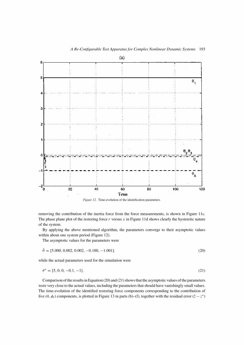
Figure 12. Time-evolution of the identification parameters.
removing the contribution of the inertia force from the force measurements, is shown in Figure 11c.The phase plane plot of the restoring force r versus x in Figure 11d shows clearly the hysteretic natureof the system.
By applying the above mentioned algorithm, the parameters converge to their asymptotic valueswithin about one system period (Figure 12).
The asymptotic values for the parameters were
θ = [5.000, 0.002, 0.002, −0.100, −1.001]. (20)
while the actual parameters used for the simulation were
θ∗ = [5, 0, 0, −0.1, −1]. (21)
Comparison of the results in Equation (20) and (21) shows that the asymptotic values of the parameterswere very close to the actual values, including the parameters that should have vanishingly small values.The time-evolution of the identified restoring force components corresponding to the contribution offive (θi .φi ) components, is plotted in Figure 13 in parts (b)–(f), together with the residual error (z − z∗)
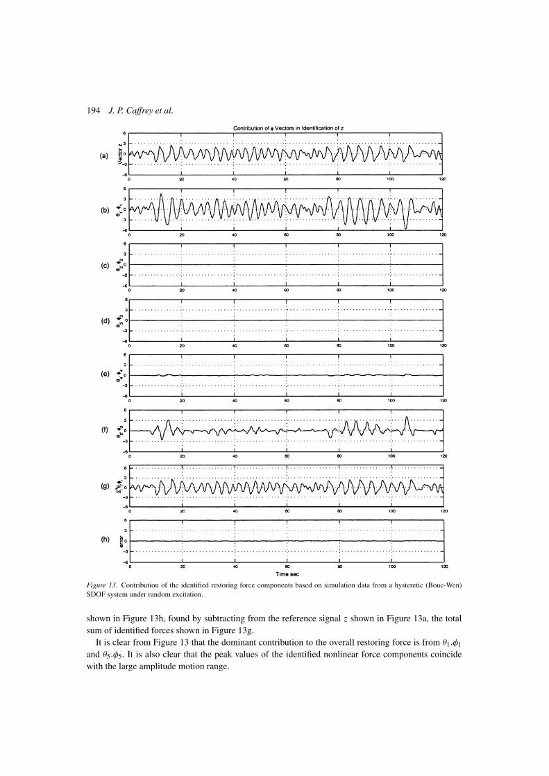
194 J. P. Caffrey et al.
Figure 13. Contribution of the identified restoring force components based on simulation data from a hysteretic (Bouc-Wen)SDOF system under random excitation.
shown in Figure 13h, found by subtracting from the reference signal z shown in Figure 13a, the totalsum of identified forces shown in Figure 13g.
It is clear from Figure 13 that the dominant contribution to the overall restoring force is from θ1.φ1
and θ5.φ5. It is also clear that the peak values of the identified nonlinear force components coincidewith the large amplitude motion range.
A Re-Configurable Test Apparatus for Complex Nonlinear Dynamic Systems 195
4.5. APPLICATION TO MEASUREMENTS FROM TEST APPARATUS
4.5.1. Derivation of a General Linear Parametric ModelThe parametric model derived in Section 4.2 is for hysteretic systems defined by only the Bouc–Wendifferential equation (Equation (3)). To derive a more general linear static parametric model that repre-sents a variety of SDOF models from linear to nonlinear, the damping, stiffness, and cubic nonlinearitypolynomial terms were added to Equation (18) in order to define a more general parametric model. Thefirst term ( A
ηx) in the Bouc–Wen model is equivalent to the stiffness term. For the general parametric
model, this term was replaced with the actual stiffness term.
s
s + λ[F − mx]︸ ︷︷ ︸
z
=
k
c
d−νβa1
η
νγ a1
η
...
−νβaN
η
νγ aN
η
T
︸ ︷︷ ︸(θ∗)T
×
s
s + λx
s
s + λx
s
s + λx3
1
s + λ|x ||r |1−1r
1
s + λx |r |1
...
1
s + λ|x |r |N−1r
1
s + λx |r |N
︸ ︷︷ ︸φ
(22)
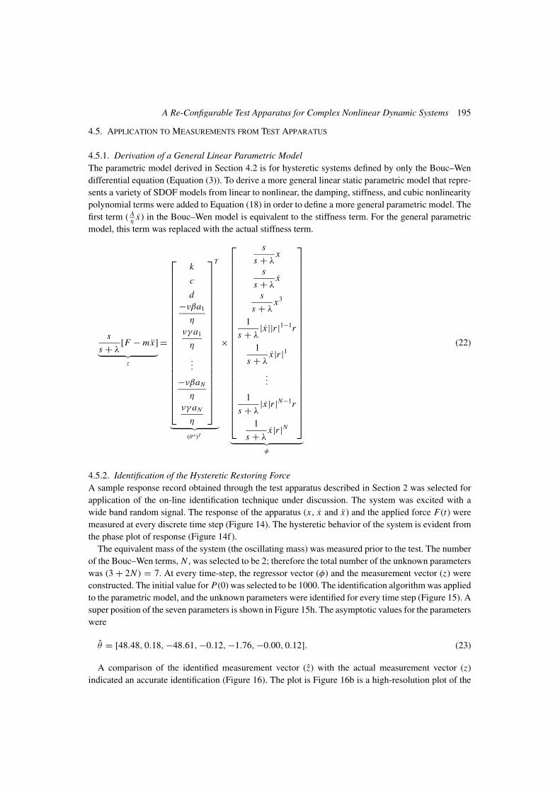
4.5.2. Identification of the Hysteretic Restoring ForceA sample response record obtained through the test apparatus described in Section 2 was selected forapplication of the on-line identification technique under discussion. The system was excited with awide band random signal. The response of the apparatus (x , x and x) and the applied force F(t) weremeasured at every discrete time step (Figure 14). The hysteretic behavior of the system is evident fromthe phase plot of response (Figure 14f).
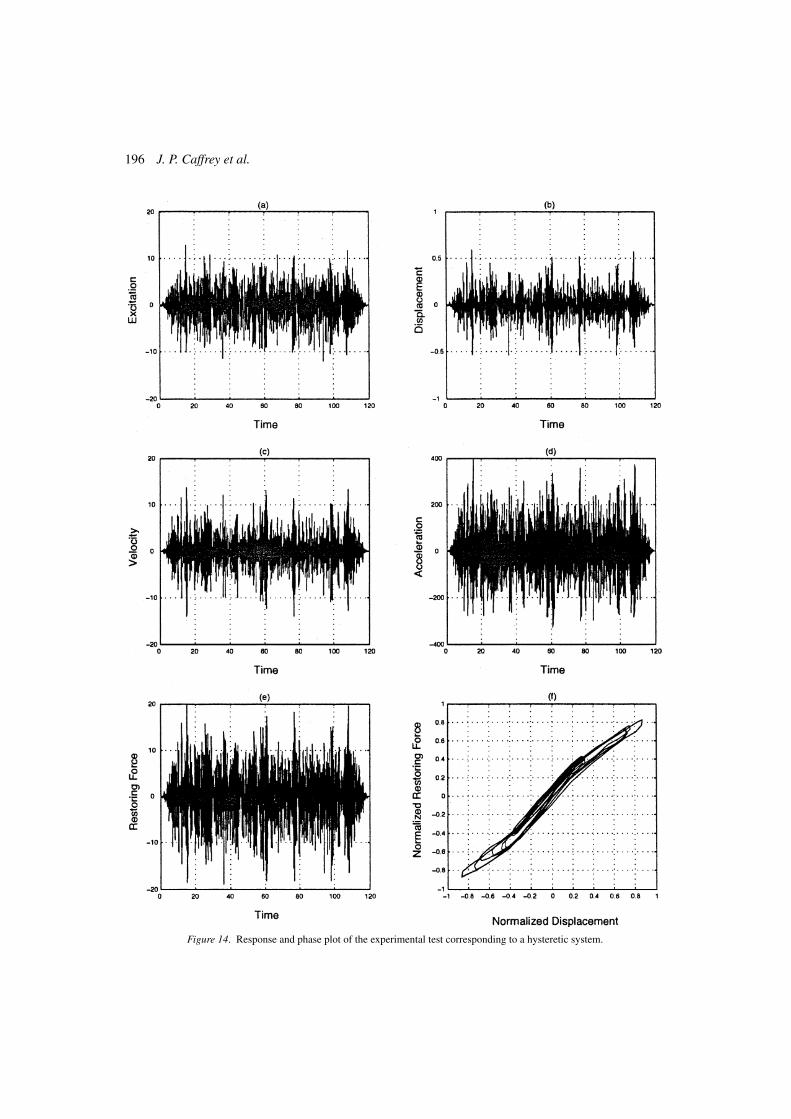
The equivalent mass of the system (the oscillating mass) was measured prior to the test. The numberof the Bouc–Wen terms, N , was selected to be 2; therefore the total number of the unknown parameterswas (3 + 2N ) = 7. At every time-step, the regressor vector (φ) and the measurement vector (z) wereconstructed. The initial value for P(0) was selected to be 1000. The identification algorithm was appliedto the parametric model, and the unknown parameters were identified for every time step (Figure 15). Asuper position of the seven parameters is shown in Figure 15h. The asymptotic values for the parameterswere
θ = [48.48, 0.18, −48.61, −0.12, −1.76, −0.00, 0.12]. (23)
A comparison of the identified measurement vector (z) with the actual measurement vector (z)indicated an accurate identification (Figure 16). The plot is Figure 16b is a high-resolution plot of the
196 J. P. Caffrey et al.
Figure 14. Response and phase plot of the experimental test corresponding to a hysteretic system.
A Re-Configurable Test Apparatus for Complex Nonlinear Dynamic Systems 197
Figure 15. Evolution of the identification parameters corresponding to the experimental data from a hysteretic system underrandom excitation.
198 J. P. Caffrey et al.
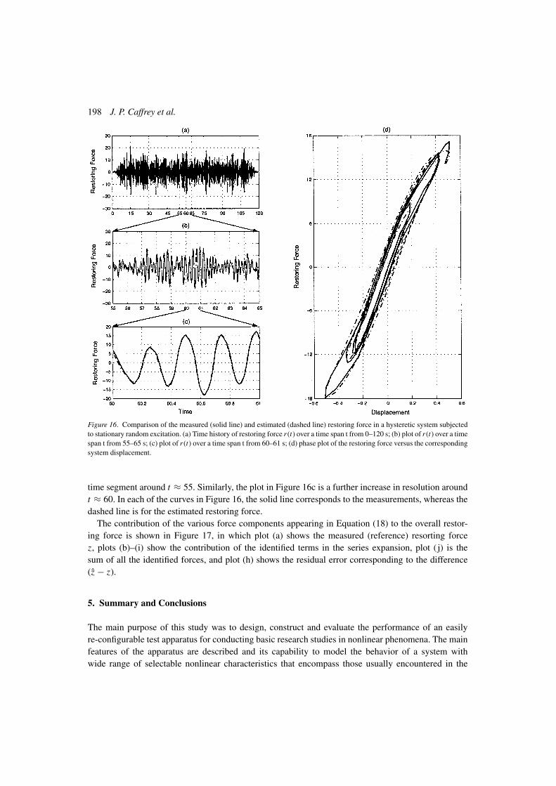
Figure 16. Comparison of the measured (solid line) and estimated (dashed line) restoring force in a hysteretic system subjectedto stationary random excitation. (a) Time history of restoring force r (t) over a time span t from 0–120 s; (b) plot of r (t) over a timespan t from 55–65 s; (c) plot of r (t) over a time span t from 60–61 s; (d) phase plot of the restoring force versus the correspondingsystem displacement.
time segment around t ≈ 55. Similarly, the plot in Figure 16c is a further increase in resolution aroundt ≈ 60. In each of the curves in Figure 16, the solid line corresponds to the measurements, whereas thedashed line is for the estimated restoring force.
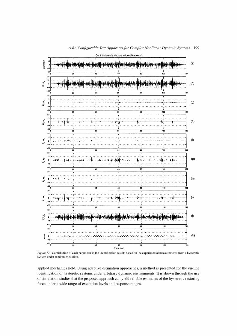
The contribution of the various force components appearing in Equation (18) to the overall restor-ing force is shown in Figure 17, in which plot (a) shows the measured (reference) resorting forcez, plots (b)–(i) show the contribution of the identified terms in the series expansion, plot ( j) is thesum of all the identified forces, and plot (h) shows the residual error corresponding to the difference(z − z).
5. Summary and Conclusions
The main purpose of this study was to design, construct and evaluate the performance of an easilyre-configurable test apparatus for conducting basic research studies in nonlinear phenomena. The mainfeatures of the apparatus are described and its capability to model the behavior of a system withwide range of selectable nonlinear characteristics that encompass those usually encountered in the
A Re-Configurable Test Apparatus for Complex Nonlinear Dynamic Systems 199
Figure 17. Contribution of each parameter in the identification results based on the experimental measurements from a hystereticsystem under random excitation.
applied mechanics field. Using adaptive estimation approaches, a method is presented for the on-lineidentification of hysteretic systems under arbitrary dynamic environments. It is shown through the useof simulation studies that the proposed approach can yield reliable estimates of the hysteretic restoringforce under a wide range of excitation levels and response ranges.
200 J. P. Caffrey et al.
Acknowledgements
This study was supported in part by grants from the US Air Force Office of Scientific Research(AFOSR), the National Science Foundation (NSF), and the National Aeronautics and Space Adminis-tration (NASA).
References
1. Ibrahim, R. A. and Pettit, C. L., ‘Uncertainties and dynamic problems of bolted joints and other fasteners’, in Proceedings ofthe IUTAM Symposium on Chaotic Dynamics and Control of Systems and Processes in Mechanics, June 8–13, 2003, Rome,Italy, Kluwer, Dordrecht, The Netherlands.
2. Worden, K., ‘Data processing and experiment design for the restoring force surface method, part I: Integration and differen-tiation of measured time data’, Mechanical Systems and Signal Processing 4(4), 1990, 295–319.
3. Smyth, A. W. and Pei, J. S., ‘Integration of response measurements for nonlinear structural health monitoring’, in Proceedingsof 3rd US–Japan Workshop on Nonlinear System Identification and Structural Health Monitoring, October 20–21, 2000,USC, Los Angeles, California.
4. Masri, S. F. and Caughey, T. K., ‘A nonparametric identification technique for nonlinear dynamic problems’, ASME Journalof Applied Mechanics. Presented at the 8th U.S. National Congress of Applied Mechanics, UCLA, 1978 46(2), June 1979,433–447.
5. Wen, Y. K., ‘Equivalent linearization for hysteretic systems under random excitations’, ASME Journal of Applied Mechanics47, 1980, 150–154.
6. Vestroni, F. and Noori, M., ‘Special issue: Hysteresis in mechanical systems, modelling and dynamic response’, InternationalJournal of Non-Linear Mechanics 37(8), 2002, 1261–1459.
7. Smyth, A. W., Sami, S. F., Kosmatoploulos, E. B., Chassiakos, A. G., and Caughey, T. K., ‘Development of adaptive modelingtechniques for non-linear hysteretic systems,’ International Journal of Non-Linear Mechanics 37(8), 2002, 1435–1451.
8. Housner, G. W. and Masri, S. F. (eds.), Proceedings of the U.S. National Workshop on Structural Control Research, Vol. 25–26.University of Southern California, Los Angeles, California, USC Publication No. M9013, 1990.
9. Housner, G. W., Bergman, L. A., Caughey, T. K., Chassiakos, A. G., Claus, R. O., Masri, S. F., Skelton, R. E., Soong, T. T.,Spencer, B. F., and Yao, J. T. P., ‘Special issue: Structural control: Past, present and future’, ASCE Journal of EngineeringMechanics 123(9), 1997, 897–971.
10. Caughey, T. K., ‘Random excitation of a system with bilinear hysteresis’, ASME Journal of Applied Mechanics 27, 1960,649–652.
11. Caughey, T. K., ‘Equivalent linearization techniques’, Journal of the Acoustical Society of America 35, 1963, 1706–1711.12. Jennings, P. C., ‘Periodic response of a general yielding structure’, ASCE, Journal of Engineering Mechanics 90(EM2), 1966,
131–166.13. Spanos, P. D., ‘Stochastic linearization in structural dynamics’, ASME Applied Mechanics Review 34(1), 1981.14. Andronikou, A. M. and Bekey, G. A., ‘Identification of hysteretic systems,’ in Proceedings of the 18th IEEE Conference on
Decision and Control, 1984, pp. 1072–1073.15. Iwan, W. D. and Cifuentes, A. O., ‘A model for system identification of degrading structures’, Earthquake Engineering and
Structural Dynamics 14(6), 1986, 877–890.16. Vinogradov, O. and Pivovarov, I., ‘Vibrations of system with non-linear hysteresis’, Journal of Sound and Vibration 111(1),
1986, 145–152.17. Jayakumar, P. and Beck, J. L., ‘System identification using non-linear structural models’, in Proceedings of the Structural
Safety Evaluation Based on System Identification Approaches, Lambracht, Germany, Glp Intl, Germany, 1987, pp. 82–102.
18. Roberts, J. B., ‘Application of averaging methods of randomly excited hysteretic systems’, in Proceedings of the IUTAMSymposium on Nonlinear Stochastic Dynamic Engineering Systems, Innsbruck, Austria, Springer-Verlag, Berlin, 1987,pp. 361–380.
19. Wen, Y. K. and Ang. A. H. S., ‘Inelastic modeling and system identification’, in Proceedings of the Structural SafetyEvaluation Based on System Identification Approaches, Lambrecht, Germany, Glp Intl, Germany, 1987, pp. 142–160.
20. Yar, M. and Hammond, J. K., ‘Modelling and response of bilinear hysteretic systems’, ASCE Journal of EngineeringMechanics 113, 1987, 1000–1013.
21. Yar, M. and Hammond, J. K., ‘Parameter estimation for hysteretic systems’, Journal of Sound and Vibration 117(1), 1987,161–172.
22. Worden, K. and Tomlinson, G. R., ‘Identification of linear nonlinear restoring force surfaces in single- and multi-modesystems’, in Proceedings of the Third International Conference on Recent Advances in Structural Dynamics, Institute ofSound and Vibration Research, Southampton, UK, 1988, pp. 299–308.
A Re-Configurable Test Apparatus for Complex Nonlinear Dynamic Systems 201
23. Sues, R. H., Mau, S. T., and Wen, Y. K., ‘System identification of degrading hysteretic restoring forces,’ ASCE Journal ofEngineering Mechanics 114, 1988, 833–846.
24. Roberts, J. B. and Spanos, P. D., Random Vibration and Statistical Linearization, Wiley, New York, 1990.25. Masri, S. F., Miller, R. K, Traina, M. I., and Caughey, T. K., ‘Development of bearing friction models from experimental
measurements’, Journal of Sound and Vibration 149(3), 1991, 159–167.26. Capecchi, D., ‘Accurate solutions and stability criterion for periodic oscillations in hysteretic systems,’ Meccanica 25, 1990,
159–167.27. Peng, C. Y. and Iwan, W. D., ‘An identification methodology for a class of hysteretic structures,’ Earthquake Engineering
and Structural Dynamics 21, 1992, 695–712.28. Loh, C. and Chung, S., ‘A three-stage identification approach for hysteretic systems’, Earthquake Engineering and Structural
Dynamics 22, 1993, 129–150.29. Chassiakos, A. G., Masri, S. F., Smyth, A. W., and Anderson, J. C., ‘Adaptive methods for identification of hysteretic
structures’, in Proceedings of the 1995 American Control Conference, Seattle, Washington, 21–23 June, IEEE ServiceCenter, Piscataway, New Jersey, 1995.
30. Benedettini, F., Capecchi, D., and Vestroni, F., ‘Identification of hysteretic oscillators under earthquake loading by nonpara-metric models’, ASCE Journal of Engineering Mechanics 121, 1995, 606–612.
31. Iwan, W. D. ‘A distributed-element model for hysteresis and its steady-state dynamic response’, ASME Journal of AppliedMechanics 33(4), 1966, 893–900.
32. Ni, Y. Q., Ko, J. M., and Wong, C. W., ‘Nonparametric identification of nonlinear hysteretic systems’, ASCE Journal ofEngineering Mechanics 125(2), 1999, 206–215.
33. Sato, T. and Qi, K., ‘Adaptive h∞ filter: its applications to structural identification’, ASCE Journal of Engineering Mechanics124(11), 1998, 1233–1240.
34. Smyth, A. W., Kosmatopoulos, E. B., Masri, S. F., and Chassiakos, A. G., ‘Adaptive identification of nonlinear hystereticstructural systems’, 2001 ASME International Mechanical Engineering Congress and Exposition, November 11–16, NewYork, ASME, 2001.
35. Worden, K. and Tomlinson, G. R., Nonlinearity in Structural Dynamics: Detection, Identification and Modelling, Instituteof Physics Publication, London, 2001.
36. Lin, J. W., Betti, R., Smyth, A. W., and Longman, R. W., ‘On-line identification of nonlinear hysteretic structural systemsusing a variable trace approach’, Earthquake Engineering & Structural Dynamics 30, 2001, 1279–1303.
37. Bouc, R., ‘Forced vibration of mechanical systems with hysteresis, abstract’, in Proceedings of the Fourth Conference onNonlinear Oscillation, Prague, Czechoslovakia, 1967, p. 315.
38. Wen, Y. K. ‘Method for random vibration of hysteretic systems’, ASCE Journal of Engineering Mechanics 102, 1976,249–263.
39. Ioannou, P. A. and Sun, J., Robust Adaptive Control, Prentice-Hall, Upper Saddle River, New Jersey, 1996.40. Ioannou, P. A. and Datta, A., ‘Robust adaptive control: A unified approach’, Proceedings of the IEEE 79(12), 1991, 1736–
1768.41. Chassiakos, A. G., Masri, S. F., Smyth, A. W., and Caughey, T. K., ‘On-line identification of hysteretic systems’, ASME
Journal of Applied Mechanics 65(1), 1998, 194–203.42. Smyth, A. W., Masri, S. F., and Chassiakos, A. G., ‘On-line parametric identification of mdof nonlinear hysteretic systems’,
ASCE Journal of Engineering Mechanics 125(2), 1999, 133–142.
Related Documents