A real-time versatile roadway path extraction and tracking on an FPGA platform Roberto Marzotto a , Paul Zoratti b , Daniele Bagni c , Andrea Colombari a , Vittorio Murino a,d,e, * a eVS embedded Vision Systems S.r.l., Ca’ Vignal 2, Strada Le Grazie 15, 37134 Verona, Italy b Xilinx, Inc., Detroit, USA c Xilinx, Inc., Milan, Italy d Dipartimento di Informatica, University of Verona, Ca’ Vignal 2, Strada Le Grazie 15, Verona, Italy e Istituto Italiano di Tecnologia (IIT), Via Morego 30, 16163 Genova, Italy article info Article history: Received 26 January 2009 Accepted 17 March 2010 Available online 4 May 2010 Keywords: Lane detection Lane tracking Road modeling Lane departure warning FPGA processing Embedded computer vision Automotive abstract This paper presents an algorithm for roadway path extraction and tracking and its implementation in a Field Programmable Gate Array (FPGA) device. The implementation is particularly suitable for use as a core component of a Lane Departure Warning (LDW) system, which requires high-performance digital image processing as well as low-cost semiconductor devices, appropriate for the high volume production of the automotive market. The FPGA technology proved to be a proper platform to meet these two con- trasting requirements. The proposed algorithm is specifically designed to be completely embedded in FPGA hardware to process wide VGA resolution video sequences at 30 frames per second. The main con- tributions of this work lie in (i) the proper selection, customization and integration of the main functions for road extraction and tracking to cope with the addressed application, and (ii) the subsequent FPGA hardware implementation as a modular architecture of specialized blocks. Experiments on real road sce- nario video sequences running on the FPGA device illustrate the good performance of the proposed sys- tem prototype and its ability to adapt to varying common roadway conditions, without the need for a per-installation calibration procedure. Ó 2010 Elsevier Inc. All rights reserved. 1. Introduction The huge population of motor vehicles and the related large number of accidents occurring on the roads have a dramatic impact on the cost to society in terms of medical expenses and lost productivity. Since a high percentage of accidents are mainly caused by human errors (due to driver distraction or other factors), Driver Assistance (DA) systems that support drivers and help pre- venting their mistakes can be effective in reducing such accidents and associated fatalities. Therefore, there is strong interest from many industrial organizations and research institutes to improve automotive safety through DA system development, which is con- sidered a very challenging task from both scientific and technolog- ical points of view. This paper presents a computer vision system prototype for roadway path extraction and tracking, which is the result of a project conducted between engineers at Xilinx and Embedded Vision Systems. The goal of the project was to implement a video processing algorithm suitable for use as a core component of a Lane Departure Warning (LDW) system in an embedded device, with a focus on achieving overall high-performance, low-cost and short development time [1]. The objective of an LDW system 1 is to alert the driver when the vehicle inadvertently strays from its road lane. Typically, it uses a forward-looking camera installed on the front of a vehicle to capture images of the roadway to identify and track the markings corre- sponding to the lane boundaries and to locate the host vehicle’s position with respect to them. When the vehicle crosses the lane bounds, the system issues a warning. Since LDW systems require high-performance digital image processing as well as low-cost devices appropriate for the high vol- umes of the automotive market, we decided to develop and imple- ment the lane detection and tracking procedures in a single Field Programmable Gate Array (FPGA) device, which represents a suit- able platform to meet these two contrasting requirements [2]. This choice is motivated by several reasons. First, FPGAs for auto- motive applications can also cope with the demanding require- ments requested by automotive safety systems, in terms of harsh working conditions and type of redundancy needed. Actually, they can work at high temperature range, e.g., Xilinx Automotive devices are available in two temperature grades, up to 100 degrees and up to 1077-3142/$ - see front matter Ó 2010 Elsevier Inc. All rights reserved. doi:10.1016/j.cviu.2010.03.015 * Corresponding author at: Dipartimento di Informatica, University of Verona, Ca’ Vignal 2, Strada Le Grazie 15, Verona, Italy. Fax: +39 045 802 7068. E-mail address: [email protected] (V. Murino). 1 In particular, authors are referring to camera-based LDW systems working in the visible range. There also exist LDW systems based on infrared technology and other types of sensors. Computer Vision and Image Understanding 114 (2010) 1164–1179 Contents lists available at ScienceDirect Computer Vision and Image Understanding journal homepage: www.elsevier.com/locate/cviu

Welcome message from author
This document is posted to help you gain knowledge. Please leave a comment to let me know what you think about it! Share it to your friends and learn new things together.
Transcript
Computer Vision and Image Understanding 114 (2010) 1164–1179
Contents lists available at ScienceDirect
Computer Vision and Image Understanding
journal homepage: www.elsevier .com/ locate /cviu
A real-time versatile roadway path extraction and tracking on an FPGA platform
Roberto Marzotto a, Paul Zoratti b, Daniele Bagni c, Andrea Colombari a, Vittorio Murino a,d,e,*
a eVS embedded Vision Systems S.r.l., Ca’ Vignal 2, Strada Le Grazie 15, 37134 Verona, Italyb Xilinx, Inc., Detroit, USAc Xilinx, Inc., Milan, Italyd Dipartimento di Informatica, University of Verona, Ca’ Vignal 2, Strada Le Grazie 15, Verona, Italye Istituto Italiano di Tecnologia (IIT), Via Morego 30, 16163 Genova, Italy
a r t i c l e i n f o a b s t r a c t
Article history:Received 26 January 2009Accepted 17 March 2010Available online 4 May 2010
Keywords:Lane detectionLane trackingRoad modelingLane departure warningFPGA processingEmbedded computer visionAutomotive
1077-3142/$ - see front matter � 2010 Elsevier Inc. Adoi:10.1016/j.cviu.2010.03.015
* Corresponding author at: Dipartimento di InformaVignal 2, Strada Le Grazie 15, Verona, Italy. Fax: +39
E-mail address: [email protected] (V. Murin
This paper presents an algorithm for roadway path extraction and tracking and its implementation in aField Programmable Gate Array (FPGA) device. The implementation is particularly suitable for use as acore component of a Lane Departure Warning (LDW) system, which requires high-performance digitalimage processing as well as low-cost semiconductor devices, appropriate for the high volume productionof the automotive market. The FPGA technology proved to be a proper platform to meet these two con-trasting requirements. The proposed algorithm is specifically designed to be completely embedded inFPGA hardware to process wide VGA resolution video sequences at 30 frames per second. The main con-tributions of this work lie in (i) the proper selection, customization and integration of the main functionsfor road extraction and tracking to cope with the addressed application, and (ii) the subsequent FPGAhardware implementation as a modular architecture of specialized blocks. Experiments on real road sce-nario video sequences running on the FPGA device illustrate the good performance of the proposed sys-tem prototype and its ability to adapt to varying common roadway conditions, without the need for aper-installation calibration procedure.
� 2010 Elsevier Inc. All rights reserved.
1. Introduction
The huge population of motor vehicles and the related largenumber of accidents occurring on the roads have a dramaticimpact on the cost to society in terms of medical expenses and lostproductivity. Since a high percentage of accidents are mainlycaused by human errors (due to driver distraction or other factors),Driver Assistance (DA) systems that support drivers and help pre-venting their mistakes can be effective in reducing such accidentsand associated fatalities. Therefore, there is strong interest frommany industrial organizations and research institutes to improveautomotive safety through DA system development, which is con-sidered a very challenging task from both scientific and technolog-ical points of view.
This paper presents a computer vision system prototype forroadway path extraction and tracking, which is the result of aproject conducted between engineers at Xilinx and EmbeddedVision Systems. The goal of the project was to implement a videoprocessing algorithm suitable for use as a core component of a LaneDeparture Warning (LDW) system in an embedded device, with a
ll rights reserved.
tica, University of Verona, Ca’045 802 7068.o).
focus on achieving overall high-performance, low-cost and shortdevelopment time [1].
The objective of an LDW system1 is to alert the driver when thevehicle inadvertently strays from its road lane. Typically, it uses aforward-looking camera installed on the front of a vehicle to captureimages of the roadway to identify and track the markings corre-sponding to the lane boundaries and to locate the host vehicle’sposition with respect to them. When the vehicle crosses the lanebounds, the system issues a warning.
Since LDW systems require high-performance digital imageprocessing as well as low-cost devices appropriate for the high vol-umes of the automotive market, we decided to develop and imple-ment the lane detection and tracking procedures in a single FieldProgrammable Gate Array (FPGA) device, which represents a suit-able platform to meet these two contrasting requirements [2].
This choice is motivated by several reasons. First, FPGAs for auto-motive applications can also cope with the demanding require-ments requested by automotive safety systems, in terms of harshworking conditions and type of redundancy needed. Actually, theycan work at high temperature range, e.g., Xilinx Automotive devicesare available in two temperature grades, up to 100 degrees and up to
1 In particular, authors are referring to camera-based LDW systems working in thevisible range. There also exist LDW systems based on infrared technology and othertypes of sensors.
2 Values for camera height from the road plane, focal length, dimensions of theCCD, and tilt angle are sufficient.
R. Marzotto et al. / Computer Vision and Image Understanding 114 (2010) 1164–1179 1165
125 degrees junction temperature, and are all AEC-Q100 qualified tomeet automotive performance. Also, Safety Integrity Level (SIL) is animportant aspect which is integrated in FPGAs: for instance, forXilinx FPGAs in particular, several methods or features can be lever-aged to meet a system wide SIL level, like the inherent parallelprocessing capability that can support double or triple moderedundancy and the continuous configuration monitoring doneautomatically in the background. These features can all be used incombination by system designers to ensure system level integrity.
In addition, FPGAs offer:
� low-power performance and design tools to be ‘‘power con-sumption aware” [3];� the possibility to reconfigure the algorithm as various roadway
conditions and scenarios are encountered;� great flexibility in manipulating the algorithm with high
abstraction level design and synthesis tools, besides the popularHardware Description Language (HDL) method;� large scalability to add more enhanced features such as road
sign recognition or intelligent headlamp control.
The last two features are particularly important advantages thatFPGAs offer over competing Application-Specific Standard Product(ASSP) or Application-Specific Integrated Circuit (ASIC) devices.While ASSP/ASIC technology might reduce the price production costper piece, this only makes sense once the design has reached its fullmaturity. In fact, in most cases, early system development phase re-quires extensive and iterative coding and testing, and FPGAs repre-sent a good trade-off among flexibility of development, possibility ofreconfigurability and testing the algorithms, real-time perfor-mances, and costs. The processing flexibility offered by the hardwareparallelism and programmability of an FPGA is unmatched by thefixed functionality of ASSP/ASIC and is a critical factor in risk reduc-tion of system development. Driver Assistance is still an emergingmarket and new algorithms/methods are being invented as engi-neers gain more experience with the incredibly wide variety of road-way scenarios in which such systems must operate. An FPGAimplementation allows design engineers to add/modify processingalgorithms much later in the development cycle than traditionalASSP/ASIC implementations, thereby reducing development risk.Furthermore, as semiconductor processing nodes continue to de-crease, now heading towards 32 nm, ASSP and ASIC developmentcosts are rising exponentially, increasing required volumes to sup-port development cost amortization. A related FPGA advantage isthe ability to scale the density of devices (and therefore the cost)based on the feature set to be provided.
The development of the proposed prototype consisted in tack-ling three main issues:
� the extraction of lane marking candidates from the edge mapwhile discarding spurious edges;� the fitting of a proper roadway model to the extracted data;� the tracking of the model parameters to get a more robust and
reliable outcome.
To solve these issues, an image pre-processing pipeline was de-signed to extract the lane marking candidates from the inputimages, and model fitting and tracking are subsequently performedby a module that estimates the road model parameters as seenfrom the vehicle.
The image pre-processing pipeline consists of various stages of2D filters: (a) Gaussian noise reduction, (b) histogram stretching,(c) edge-detection devoted to compute gradient magnitudes andphases, (d) edge thinning with automatic thresholding generatinga binary edge map, (e) morphological filtering to clean the resultingdata, and, finally, (f) lane marking pattern search aimed at selecting
a subset of edge points having a particular configuration and orien-tation, thus effectively facilitating the subsequent lane extraction.
The model fitting and tracking subsystem has the purpose ofestimating the road lane model: a cascade of two RANdom SAmpleand Consensus (RANSAC) stages is applied to robustly fit theparameters of a parabolic model on the extracted lane markingdata, followed by Kalman filtering to track them in real-time.
Overall, the main contributions of this work lie in (i) the designof a complex computer vision system as a combination and inte-gration of algorithms working both in the pixel and feature do-mains, and (ii) their proper customization and tuning for anFPGA implementation, which required the design of original solu-tions aimed at balancing the computational burden, the functionalperformances, and the usage of the device resources.
The proposed system architecture is composed of self-containedlogic modules that need no support from programmable micro-con-trollers, DSP processors or external memories: all the modules arecompletely implemented inside the FPGA. This is a very importantnovelty, making the proposed system quite unique because not onlytraditional low-level image processing algorithms, but also high-le-vel fitting and tracking strategies have been designed and imple-mented in FPGA. Typically, other video processing systems makeonly a partial use of the FPGA devices, combining them with otherexternal components like DSP processors [4]. In fact, to the best ofthe authors’ knowledge, only the work proposed in [5] utilizes asolution completely embedded in an FPGA, similar to ours, but theapproach is quite different. It implements a soft-CPU that runs sim-plified C/C++ code, hence not exploiting the customization propertyof the FPGAs and their capability to optimize parallel processing.
Furthermore, the adoption of the model-based design [1] of-fered an efficient and straightforward method for transitioningfrom a purely software model to a real-time FPGA-based hardwareprototype, without the need of complex HDL coding. In contrast tothe relatively slow processing of the pure software model, theFPGA implementation supports processing wide VGA (WVGA)images at 30 frames per second.
It is also worth noticing that the described system does not re-quire an ad hoc camera calibration for each installation, but onlyfew parameters have to be initially fixed depending on somenon-stringent hardware specifications on the camera setup.2
During the experimental phase of the project, the systemproved to be robust and suitable to cope with several road condi-tions as reliable results have been obtained even when roads werecluttered, shadows were present, and lane markings were unclearor partly masked.
The remainder of the paper is organized as follows: Section 2outlines the previous work for lane detection and tracking from apoint of view oriented to the target FPGA implementation, and con-sequently enriched with proper considerations. Section 3 describesin detail the proposed solution starting from the adopted road mod-el: for each stage of the system, the characteristics of the imple-mented algorithms are also reported as compared to the currentliterature. Section 4 is devoted to describe the FPGA implementa-tion and the specific issues faced during this phase. Section 5 illus-trates the results using actual freeway image sequences, and acritical analysis is provided to show performances and limitations.The work is summarized and conclusions are reported in Section 6.
2. Related work
Several algorithms for roadway path extraction and trackinghave been proposed in the last decade [6–26], whose differences
1166 R. Marzotto et al. / Computer Vision and Image Understanding 114 (2010) 1164–1179
mainly consist in the adopted image pre-processing pipeline, thelane model, the selected model fitting method and the trackingstrategy.
In the literature, only few systems use FPGA devices or otherlow-cost and low-power consumption architectures. For example,the system called GOLD [6] is based on the PArallel PRocessor forImage Checking and Analysis (PAPRICA) co-processor which is alow-cost special-purpose massively parallel architecture composedof 256 slow clocked processing elements integrated on a single VMEboard connected to a SPARC-based architecture. In [7], in order toreduce the computational burden of the main processor, an FPGAco-processor is employed for some low-level tasks like pre-filteringand sub-sampling. Similarly, the LDW system proposed by TRW3
uses the FPGA only for edge detection and feature extraction. In[17], lane detection is carried out using 3D data extracted by a hard-ware–software co-designed system implemented in FPGA, while therest of the processing is performed by an embedded processor. An-other example can be found in [32], where an embedded portableLDW system based on an ARM processor and FPGA is proposed. Inthis architecture, FPGA is exploited for the image pre-processing(low-pass filtering and edge detection) and data transfer among thememory bus, the sensor device, and the LCD display. The rest of theprocessing (lane detection and lane departure warning mechanismbased on the spatio-temporal procedure) is carried out by the proces-sor in software. In [33], a real-time algorithm for line keeping is pre-sented, which is implemented on a Celoxica RC203 board equippedwith a Xilinx Virtex II FPGA. The steering angle estimation (actualy,no tracking is performed) is based on the detection of the lane mark-ings via road segmentation using adaptive histogram thresholding.The performances are quite good in terms of speed (39 frames persecond) and steering angle accuracy on roads freed by nearby cars. Fi-nally, as already quoted in Section 1, [5] utilizes a solution completelyembedded in an FPGA but, implementing a soft-CPU core as maincomponent, it suffers from significant limitations in exploiting thecapability to optimize the parallel processing.
Regarding the individual processing stages, many algorithmshave been proposed in the past. A class of methods for imagepre-processing usually computes an edge map of lane markingcandidate points [9–11,15,18–21,25,26], which is subsequently in-put to the model-based fitting to detect the road model. The edgemap can be obtained using standard methods such as Canny[11,15,18] or Sobel [9,10,12,13], or by custom methods based ondark–light–dark transition detection [6,7,22,26]. Other algorithmsprefer to fit the model directly on the whole gradient map by max-imizing a likelihood function [8,24]. In order to prune out spuriousedge points, some constraints can be exploited. For example, to de-tect plausible directions of the lane markings, steerable filters areused [19], which also helps to filter out edges with disqualifyinggradient directions. The same idea is used in [10,17], where theHough Transform accumulator space is reduced around plausiblevalues. In [21,26], left and right lane markings candidate pointsare discriminated by using the gradient sign of the edge pixels.Lane marking width [23,26] together with or in alternative to roadand lane marking colors [12,15,23] can be used for pixel classifica-tion purposes. Typically, in order to obtain a better edge map, edgedetection can be preceded by a Gaussian filter to reduce noise [15],or followed by edge thinning stage to get more accurate contours[9]. In [6,19], the image is first warped to get a bird-eye view in or-der to subsequently exploit the parallelism between lane markingsusing various heuristics. This constraint can also be exploited with-out the time consuming warping stage at the Euclidean coordi-nates level using projection formulas [9,16]. Notice that, despitegood performances, the methods using image or coordinates’
3 http://www.trw.com/.
projection require sensor calibration which can be problematic inreal-world automotive applications.
The lane model may vary from a simple one to a complex one:straight-lines [10,15,17,18], piece-wise linear [9,23], parabolicapproximation on the flat (road) plane [8,12,13,19–21,24,27], cubicB-splines [11], cubic splines [25], and clothoid [7,14,16,22,26]; thelatter being a 3D model which should be combined with stereosystems (also requiring accurate calibration themselves). Obvi-ously, more complicated models require more processing re-sources for the fitting stage because of the larger number ofparameters to be estimated. Since the final goal is a low-costimplementation on an FPGA platform, the decision about whichmodel to adopt is critical. In the authors’ opinion, the model withthe best trade-off between modeling capabilities and performanceimpact is the parabolic approximation.
Once the road model has been selected, the data-model fittingcan be carried out in many ways. A possible class of methods isconstituted by the Hough Transform (HT) [10,11,15,17], and itsvariants like the Randomized Hough Transform (RHT) [24] andthe Adaptive Randomized Hough Transform (ARHT) [12]. Alterna-tives to HT-based techniques are the RANSAC algorithm and itsvariants [21,25], the minimization of a target function [11,26], orexploiting probabilistic approaches [8,20,24,25].
RHT implements HT as a series of random trials. As elucidated in[28], RHT is similar to RANSAC, but the main difference is that RAN-SAC does not use score accumulation in the parameter space, so it isnot appropriate for finding multiple model instances but just themost voted. ARHT is a variant of the RHT inspired by particle filter-ing where all the image points are considered in the random sam-pling stage, but they are weighted using gradient information.Moreover, ARHT also combines a multi-resolution strategy to in-crease accuracy. In order to have a more robust fitting, an interest-ing constraint is given by vanishing points: the parallelism betweenlane markings on the ground corresponds to a vanishing point con-straint in the image plane. For example, this constraint has beenused in [10,18] to reduce the HT accumulator space, and in [11]to compute vanishing point candidates, subsequently used for lineclassification purposes.
In the proposed work, considering that the final algorithm is tobe implemented in FPGA, effective but simple4 fitting and trackingprocedures were chosen. For model fitting, both probabilistic andminimization-based approaches, as well as ARHT were discarded be-cause they were considered too computationally expensive. Thestorage requirements of the classical HT can be a limit for an FPGAimplementation, so it was also discarded. Though the improvementsoffered by RHT (small storage requirements, improved perfor-mances, and higher parameter resolution) seem suitable for beingembedded in an FPGA, RHT needs dynamic accumulator construc-tion but dynamic memory allocation is difficult to be implementedin an FPGA.
Consequently, the final choice for the model fitting algorithm inthe proposed prototype is a RANSAC-like approach due to the fol-lowing advantages: (i) it is not memory consuming, (ii) it does notneed a peak detection stage, (iii) it is robust to outliers, (iv) it isflexible as it can be adapted to different lane models without rad-ically changing the implementation, and (v) its processing time canbe trimmed by changing the number of iterations.
Model tracking, when present, is usually performed by a Kal-man Filter (KF) [17,19,26], an Extended Kalman Filter (EKF)[7,14,22] or a Particle Filter (PF) [15,25,20]. Some approaches donot differentiate between model fitting and tracking, but theyuse a single global tracking stage able to directly relate image data
4 Simple in terms of number and type of the operations, in particular floating pointsage and memory consumption are critical from the point of view of resourceccupation.
uo
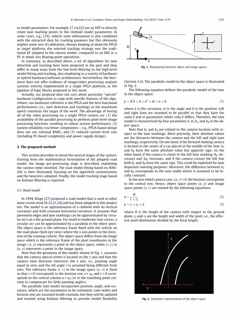
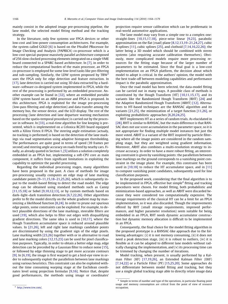
Fig. 1. Relationship between object and image spaces.
R. Marzotto et al. / Computer Vision and Image Understanding 114 (2010) 1164–1179 1167
to model parameters. For example, [7,14,22] use an EKF to directlyrelate lane marking points to the clothoid model parameters. Insome cases, e.g., [19], vehicle state information is also combinedwith the extracted data for tracking purposes but this obviouslyimplies some sort of calibration. Always keeping in mind the FPGAas target platform, the selected tracking strategy was the tradi-tional KF adapted to the chosen model: compared to an EKF or aPF, it needs less floating point operations.
In summary, as described above, a lot of algorithms for lanedetection and tracking have been proposed in the past and theydiffer in many ways from the low-level filtering to the high-levelmodel fitting and tracking, also employing in a variety of hardwareor hybrid hardware/software architectures. Nevertheless, the liter-ature does not offer evidence of image/video processing analysissystems entirely implemented in a single FPGA platform, as thepipeline of logic blocks proposed in this work.
Actually, our proposal does not care about particular ‘‘special”hardware configuration to cope with specific features of the algo-rithms: our hardware reference is the FPGA and the best functionalperformances (i.e., lane detection and tracking) at the maximumspeed constitute the target of the work. The advantage of havingall of the video processing on a single FPGA centers on: (1) theavailability of the parallel processing to perform pixel-level imageprocessing functions resulting in robust system performance, (2)system reliability (via fewer components – e.g., FPGA-based designdoes not use external RAM), and (3) reduced system level cost(including PC-board complexity and power supply design).
3. The proposed method
This section describes in detail the several stages of the system.Starting from the mathematical formulation of the adopted roadmodel, the image pre-processing stage is described, explainingthe various steps involved. The road model fitting based on RAN-SAC is then illustrated, focusing on the algorithm customizationand the heuristics adopted. Finally, the model tracking stage basedon Kalman filtering is reported.
Fig. 2. Schematic representation of the object space.
3.1. Road model
In 1994, Kluge [27] proposed a road model that is used in othermore recent work [8,12,21,24] and has been adopted in this projecttoo. The model is an approximation of a clothoid with no verticalcurvature and with constant horizontal curvature. It assumes thatpavement edges and lane markings can be approximated by circu-lar arcs on a flat ground plane. For small to moderate lane curves, acircular arc can be approximated by a parabola in the object space.The object space is the reference frame fixed with the vehicle onthe road plane (bird-eye view) where the x axis points in the direc-tion of the running vehicle. The object space differs from the imagespace which is the reference frame of the pixel coordinates in theimage: (x, y) represents a point in the object space, while (r, c) or(u, v) represents a point in the image space.
Note that the geometry of this model, shown in Fig. 1, assumesthat the camera optical center is located on the z axis and that thecamera view direction intersects the x axis, i.e., panning angleequal to zero, and the tilt angle h is assumed being different fromzero. The reference frame (r, c) in the image space (u, v) is fixedso that r = 0 corresponds to the horizon row v = v0, and c = 0 corre-sponds to the central column u = u0 (or to the vanishing point col-umn to compensate for little panning angles).
The parabolic lane model incorporates position, angle, and cur-vature, which are the parameters to be estimated. Lane width andhorizon row are assumed locally constant, but they will be updatedand tracked using Kalman filtering to provide model flexibility
(Section 3.4). The parabolic model in the object space is illustratedin Fig. 2.
The following equation defines the parabolic model of the lanein the object space:
y ¼ 0:5� k� x2 þm� xþ b ð1Þ
where k is the curvature, m is the angle and b is the position. Leftand right lines are assumed to be parallel so that they have thesame k and m parameters whilst only b differs. Therefore, the lanemodel is characterized by four parameters k, m, bL, and bR in the ob-ject space.
Note that bL and bR are related to the camera location with re-spect to the lane markings. More precisely, their absolute valuesare the distances between the camera and the left and right lanemarkings, respectively. On one hand, if the forward-looking camerais located in the center of a car placed in the middle of the lane, bL
and bR have the same absolute value but opposite sign; on theother hand, if the camera is closer to the left lane marking jbLj de-creases and jbRj increases, and if the camera crosses the left lineboth bL and bR have the same sign. This could be exploited for lanedeparture warning purposes. Moreover, the difference between bL
and bR corresponds to the lane width which is assumed to be lo-cally constant.
In the non-tilted camera case, i.e., h = 0, the horizon correspondsto the central row. Hence, object space points (x, y) and imagespace points (r, c) are related by the following equations:
x ¼ Hr � rf
ð2Þ
y ¼ c � cf � x ð3Þ
where H is the height of the camera with respect to the groundplane, rf and cf are the height and width of the pixel, i.e., the effec-tive pixel dimensions divided by the focal length.
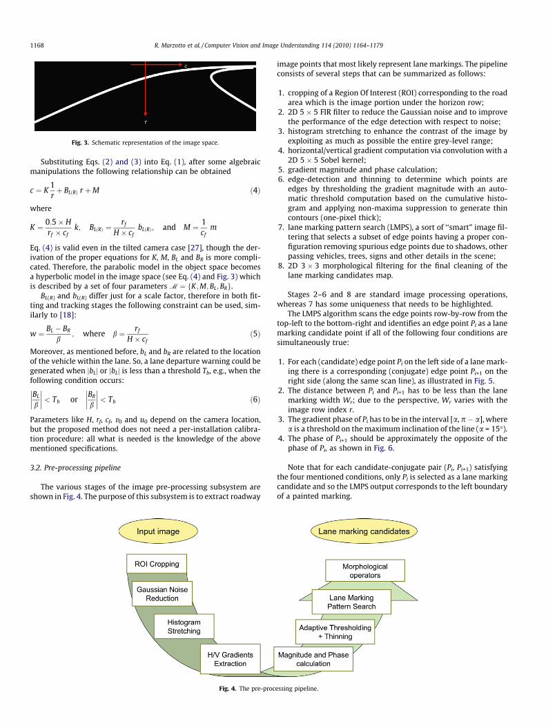
Fig. 3. Schematic representation of the image space.
1168 R. Marzotto et al. / Computer Vision and Image Understanding 114 (2010) 1164–1179
Substituting Eqs. (2) and (3) into Eq. (1), after some algebraicmanipulations the following relationship can be obtained
c ¼ K1rþ BLðRÞ r þM ð4Þ
where
K ¼ 0:5� Hrf � cf
k; BLðRÞ ¼rf
H � cfbLðRÞ; and M ¼ 1
cfm
Eq. (4) is valid even in the tilted camera case [27], though the der-ivation of the proper equations for K, M, BL and BR is more compli-cated. Therefore, the parabolic model in the object space becomesa hyperbolic model in the image space (see Eq. (4) and Fig. 3) whichis described by a set of four parameters M ¼ fK;M;BL; BRg.
BL(R) and bL(R) differ just for a scale factor, therefore in both fit-ting and tracking stages the following constraint can be used, sim-ilarly to [18]:
w ¼ BL � BR
b; where b ¼ rf
H � cfð5Þ
Moreover, as mentioned before, bL and bR are related to the locationof the vehicle within the lane. So, a lane departure warning could begenerated when jbLj or jbLj is less than a threshold Tb, e.g., when thefollowing condition occurs:
BL
b
�������� < Tb or
BR
b
�������� < Tb ð6Þ
Parameters like H, rf, cf, v0 and u0 depend on the camera location,but the proposed method does not need a per-installation calibra-tion procedure: all what is needed is the knowledge of the abovementioned specifications.
3.2. Pre-processing pipeline
The various stages of the image pre-processing subsystem areshown in Fig. 4. The purpose of this subsystem is to extract roadway
Fig. 4. The pre-proc
image points that most likely represent lane markings. The pipelineconsists of several steps that can be summarized as follows:
1. cropping of a Region Of Interest (ROI) corresponding to the roadarea which is the image portion under the horizon row;
2. 2D 5 � 5 FIR filter to reduce the Gaussian noise and to improvethe performance of the edge detection with respect to noise;
3. histogram stretching to enhance the contrast of the image byexploiting as much as possible the entire grey-level range;
4. horizontal/vertical gradient computation via convolution with a2D 5 � 5 Sobel kernel;
5. gradient magnitude and phase calculation;6. edge-detection and thinning to determine which points are
edges by thresholding the gradient magnitude with an auto-matic threshold computation based on the cumulative histo-gram and applying non-maxima suppression to generate thincontours (one-pixel thick);
7. lane marking pattern search (LMPS), a sort of ‘‘smart” image fil-tering that selects a subset of edge points having a proper con-figuration removing spurious edge points due to shadows, otherpassing vehicles, trees, signs and other details in the scene;
8. 2D 3 � 3 morphological filtering for the final cleaning of thelane marking candidates map.
Stages 2–6 and 8 are standard image processing operations,whereas 7 has some uniqueness that needs to be highlighted.
The LMPS algorithm scans the edge points row-by-row from thetop-left to the bottom-right and identifies an edge point Pi as a lanemarking candidate point if all of the following four conditions aresimultaneously true:
1. For each (candidate) edge point Pi on the left side of a lane mark-ing there is a corresponding (conjugate) edge point Pi+1 on theright side (along the same scan line), as illustrated in Fig. 5.
2. The distance between Pi and Pi+1 has to be less than the lanemarking width Wr; due to the perspective, Wr varies with theimage row index r.
3. The gradient phase of Pi has to be in the interval [a, p � a], wherea is a threshold on the maximum inclination of the line (a = 15�).
4. The phase of Pi+1 should be approximately the opposite of thephase of Pi, as shown in Fig. 6.
Note that for each candidate-conjugate pair (Pi, Pi+1) satisfyingthe four mentioned conditions, only Pi is selected as a lane markingcandidate and so the LMPS output corresponds to the left boundaryof a painted marking.
essing pipeline.
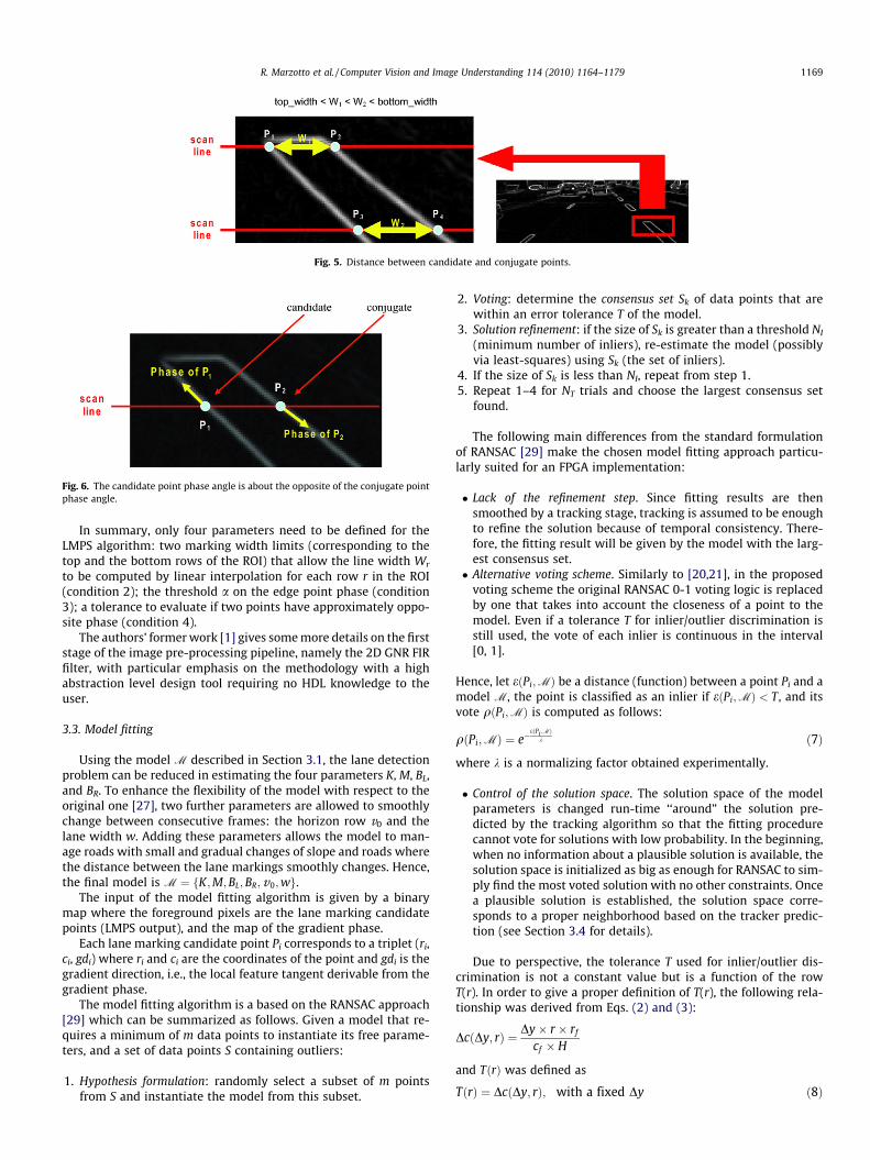
Fig. 5. Distance between candidate and conjugate points.
Fig. 6. The candidate point phase angle is about the opposite of the conjugate pointphase angle.
R. Marzotto et al. / Computer Vision and Image Understanding 114 (2010) 1164–1179 1169
In summary, only four parameters need to be defined for theLMPS algorithm: two marking width limits (corresponding to thetop and the bottom rows of the ROI) that allow the line width Wr
to be computed by linear interpolation for each row r in the ROI(condition 2); the threshold a on the edge point phase (condition3); a tolerance to evaluate if two points have approximately oppo-site phase (condition 4).
The authors’ former work [1] gives some more details on the firststage of the image pre-processing pipeline, namely the 2D GNR FIRfilter, with particular emphasis on the methodology with a highabstraction level design tool requiring no HDL knowledge to theuser.
3.3. Model fitting
Using the model M described in Section 3.1, the lane detectionproblem can be reduced in estimating the four parameters K, M, BL,and BR. To enhance the flexibility of the model with respect to theoriginal one [27], two further parameters are allowed to smoothlychange between consecutive frames: the horizon row v0 and thelane width w. Adding these parameters allows the model to man-age roads with small and gradual changes of slope and roads wherethe distance between the lane markings smoothly changes. Hence,the final model is M ¼ fK;M;BL; BR; v0;wg.
The input of the model fitting algorithm is given by a binarymap where the foreground pixels are the lane marking candidatepoints (LMPS output), and the map of the gradient phase.
Each lane marking candidate point Pi corresponds to a triplet (ri,ci, gdi) where ri and ci are the coordinates of the point and gdi is thegradient direction, i.e., the local feature tangent derivable from thegradient phase.
The model fitting algorithm is a based on the RANSAC approach[29] which can be summarized as follows. Given a model that re-quires a minimum of m data points to instantiate its free parame-ters, and a set of data points S containing outliers:
1. Hypothesis formulation: randomly select a subset of m pointsfrom S and instantiate the model from this subset.
2. Voting: determine the consensus set Sk of data points that arewithin an error tolerance T of the model.
3. Solution refinement: if the size of Sk is greater than a threshold NI
(minimum number of inliers), re-estimate the model (possiblyvia least-squares) using Sk (the set of inliers).
4. If the size of Sk is less than NI, repeat from step 1.5. Repeat 1–4 for NT trials and choose the largest consensus set
found.
The following main differences from the standard formulationof RANSAC [29] make the chosen model fitting approach particu-larly suited for an FPGA implementation:
� Lack of the refinement step. Since fitting results are thensmoothed by a tracking stage, tracking is assumed to be enoughto refine the solution because of temporal consistency. There-fore, the fitting result will be given by the model with the larg-est consensus set.� Alternative voting scheme. Similarly to [20,21], in the proposed
voting scheme the original RANSAC 0-1 voting logic is replacedby one that takes into account the closeness of a point to themodel. Even if a tolerance T for inlier/outlier discrimination isstill used, the vote of each inlier is continuous in the interval[0, 1].
Hence, let eðPi;MÞ be a distance (function) between a point Pi and amodel M, the point is classified as an inlier if eðPi;MÞ < T , and itsvote qðPi;MÞ is computed as follows:
qðPi;MÞ ¼ e�eðPi ;MÞ
k ð7Þ
where k is a normalizing factor obtained experimentally.
� Control of the solution space. The solution space of the modelparameters is changed run-time ‘‘around” the solution pre-dicted by the tracking algorithm so that the fitting procedurecannot vote for solutions with low probability. In the beginning,when no information about a plausible solution is available, thesolution space is initialized as big as enough for RANSAC to sim-ply find the most voted solution with no other constraints. Oncea plausible solution is established, the solution space corre-sponds to a proper neighborhood based on the tracker predic-tion (see Section 3.4 for details).
Due to perspective, the tolerance T used for inlier/outlier dis-crimination is not a constant value but is a function of the rowT(r). In order to give a proper definition of T(r), the following rela-tionship was derived from Eqs. (2) and (3):
Dc Dy; rð Þ ¼ Dy� r � rf
cf � H
and TðrÞ was defined as
TðrÞ ¼ Dc Dy; rð Þ; with a fixed Dy ð8Þ
1170 R. Marzotto et al. / Computer Vision and Image Understanding 114 (2010) 1164–1179
Given two points (r1, c1) and (r2, c2) belonging to the lane markings,K and M parameters are related to the image gradient directions gd1
and gd2 by the following equations that do not contain BL(R) [27]:
K ¼ ðc1 � c2Þ þ gd1 � r1 � gd2 � r2
2� 1r1� 1
r2
� � ð9Þ
M ¼ c1 �2Kr1þ gd1 � r1 ð10Þ
Eqs. (9) and (10) allow to split the fitting procedure in two subse-quent stages as suggested by [12,24]: two RANSAC-like fitting pro-cedures applied in cascade to estimate first K and M, and then BL
and BR.
3.3.1. K and M estimationStarting from a given solution space and a set of lane marking
candidate points Pi with coordinates (ri, ci) centered in (u0, v0),the algorithm performs the following operations for each iteration:
1. random sampling of a pair of points (r1, c1) and (r2, c2);2. random picking a delta horizon value dh in a small set of possi-
ble values, e.g., [�8, �4, �2, 0, 2, 4, 8] at wide VGA resolution752 � 480; this is used to adapt the horizon row v0 to smalldeviations from the current lane model as previouslymentioned;
3. hypothesis formulation by calculating candidate K and M usingthe selected pair of points and Eqs. (9) and (10), also consider-ing dh;
4. if K and M are inside the solution space then voting follows,otherwise repeat from step 1;
5. during voting each lane marking candidate point Pi = (ri,ci) isclassified as inlier if the following condition is satisfied
e Pi; fK;M; dhgð Þ ¼ 2Kri � dh
� gdi ðri � dhÞ þM� �
� ci
�������� < TðriÞ
where TðriÞ is defined in Eq. (8). Therefore, if the point is an in-lier, its vote is computed by using Eq. (7);
6. the model M ¼ fK;M; dhg with the largest sum of votes RM willbe the solution if its number of inliers is larger than a thresholdNK;M
I .
Since the most critical inliers for K and M are those at the top ofthe image where the curvature mostly biases the shape of the lanemarkings, the votes computation was modified in order to reducethe value of the votes at the bottom as compared to those at thetop on equal residual values. This was obtained just multiplyingEq. (7) by a linear function of the row index obtaining:
q0ðPi;MÞ ¼ qðPi;MÞ � 1� ri
2� rmax
� �ð11Þ
where rmax is the last row of the cropped ROI.
3.3.2. BL and BR estimationThis function outputs BL and BR starting from a given solution
space, the parameters K, M, and dh computed by the previousphase, the set of lane marking candidate points P0i ¼ ðr0i; c0iÞ with re-spect to the new horizon v 00 ¼ v0 þ dh, and the currently estimatedlane width w.
For each iteration, the following operations are carried out:
1. random sampling of a pair of points ðr01; c01Þ and ðr02; c02Þ. Noticethat, similarly to [21], the two points are now selected fromtwo different partitions of the candidate points set on the basisof the sign of the gradient direction, so that the pair will becomposed of a left and a right point;
2. hypothesis formulation by calculating candidate BL and BR usingthe selected pair of points and Eq. (4);
3. compute the lane width w using Eq. (5);4. if BL, BR, and w are inside the solution space, voting is per-
formed, otherwise repeat from step 1;5. voting is done independently for the two parameters BL and BR;
during voting, each lane marking candidate point P0i ¼ ðr0i; c0iÞ isclassified as inlier if the following condition is satisfied
eðP0i; fK;M;BLðRÞ; v 00;wgÞ ¼Kr0iþ r0i BLðRÞ þM � c0i
�������� < Tðr0iÞ
where Tðr0iÞ is defined in Eq. (8). Therefore, if the point is an in-lier, its vote is computed by using Eq. (7);
6. the model M ¼ fK;M;BL;BR;v 00;wg obtaining the largest sum ofvotes RM will be the solution if the number of inliers is largerthan a threshold NB
I .
There are three particular cases in which only one B (BL or BR)can be obtained:
� if one of the two partitions defined in the random sampling stepis not enough populated;� if only BL or BR is in the solution space;� if the constraint on the lane width w fails.
In the first case, points are picked from the bigger partitiononly; in the second case, only the parameter in the solution spaceis considered for further processing; in the third case, only themost voted parameter is considered valid.
3.4. Model tracking
The tracking algorithm is composed of three independent KFsworking respectively on K, M, and on the quadruple {BL, BR, h, w}.A constant velocity motion model is used for K, M, BL and BR, whereash and w are modeled as constant values. Moreover, Eq. (5) allows tosuppose that BL and BR vary together at the same velocity. The nota-tion used in this section is coherent with the one used in [30].
The used KFs assume no control input, so that the true state x ofthe i-th KF at time k is evolved from the state at instant (k � 1)according to
xi;k ¼ Fixi;k�1 þxi ð12Þ
where Fi is the state transition matrix of the i-th KF and xi is thecorrespondent noise process which is assumed to be uniformly dis-tributed as xi � Nð0;Q iÞ. At time k, an observation zi;k of the i-th KFis modeled according to
zi;k ¼ Hi xi;k þ mi;k
where Hi is the observation matrix of the i-th KF and vk is the cor-respondent observation noise which is assumed to be distributed asmk � Nð0;RkÞ.
As the used notation suggests, the observation covariance ma-trix Ri,k changes run-time whereas matrices Fi, Qi, and Hi are as-sumed to be a priori fixed. In fact, Ri,k is updated after the fittingstage by using the following equation:
Ri;k ¼ Rmaxi e�
�RMc
�2 2
ð13Þ
where RM is the sum of votes of the RANSAC solution, Rmaxi is a diag-
onal covariance matrix containing very large variance values and c isa normalization factor. Notice that the exponential function can beseen as a probability: the lower the sum of votes, the larger the prob-ability of obtaining a corrupted fitting. In this way, the smoothinglevel is proportional to the unreliability of the output of the fitting.
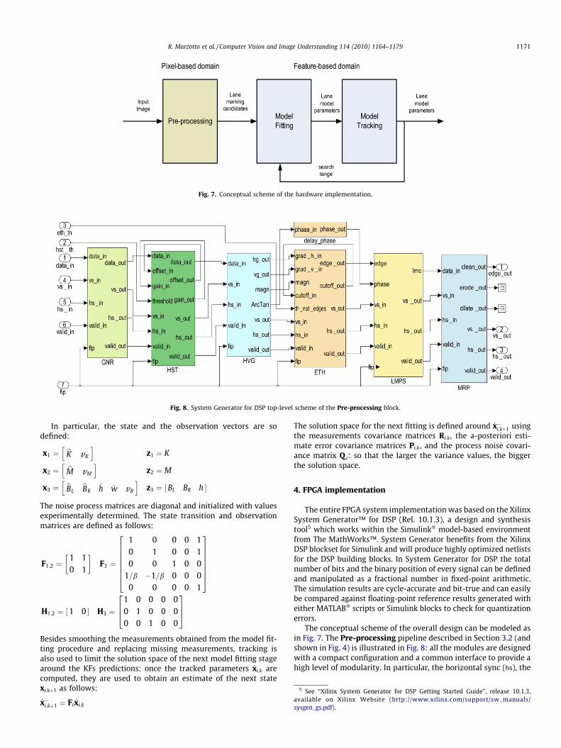
Fig. 7. Conceptual scheme of the hardware implementation.
Fig. 8. System Generator for DSP top-level scheme of the Pre-processing block.
5 See ‘‘Xilinx System Generator for DSP Getting Started Guide”, release 10.1.3available on Xilinx Website (http://www.xilinx.com/support/sw_manualssysgen_gs.pdf).
R. Marzotto et al. / Computer Vision and Image Understanding 114 (2010) 1164–1179 1171
In particular, the state and the observation vectors are sodefined:
x1 ¼ bK vK
h iz1 ¼ K
x2 ¼ bM vM
h iz2 ¼ M
x3 ¼ bBLbBR h w vB
h iz3 ¼ BL BR h½ �
The noise process matrices are diagonal and initialized with valuesexperimentally determined. The state transition and observationmatrices are defined as follows:
F1;2 ¼1 10 1
F3 ¼
1 0 0 0 10 1 0 0 10 0 1 0 0
1=b �1=b 0 0 00 0 0 0 1
26666664
37777775
H1;2 ¼ 1 0½ � H3 ¼1 0 0 0 00 1 0 0 00 0 1 0 0
264
375
Besides smoothing the measurements obtained from the model fit-ting procedure and replacing missing measurements, tracking isalso used to limit the solution space of the next model fitting stagearound the KFs predictions: once the tracked parameters xi;k arecomputed, they are used to obtain an estimate of the next statexi;kþ1 as follows:
x�i;kþ1 ¼ Fixi;k
The solution space for the next fitting is defined around x�i;kþ1 usingthe measurements covariance matrices Ri;k, the a-posteriori esti-mate error covariance matrices Pi;k, and the process noise covari-ance matrix Q i: so that the larger the variance values, the biggerthe solution space.
4. FPGA implementation
The entire FPGA system implementation was based on the XilinxSystem Generator™ for DSP (Rel. 10.1.3), a design and synthesistool5 which works within the Simulink� model-based environmentfrom The MathWorks™. System Generator benefits from the XilinxDSP blockset for Simulink and will produce highly optimized netlistsfor the DSP building blocks. In System Generator for DSP the totalnumber of bits and the binary position of every signal can be definedand manipulated as a fractional number in fixed-point arithmetic.The simulation results are cycle-accurate and bit-true and can easilybe compared against floating-point reference results generated witheither MATLAB� scripts or Simulink blocks to check for quantizationerrors.
The conceptual scheme of the overall design can be modeled asin Fig. 7. The Pre-processing pipeline described in Section 3.2 (andshown in Fig. 4) is illustrated in Fig. 8: all the modules are designedwith a compact configuration and a common interface to provide ahigh level of modularity. In particular, the horizontal sync (hs), the
,/
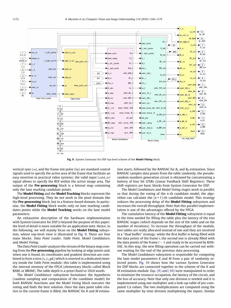
Fig. 9. System Generator for DSP top-level scheme of the Model Fitting block.
1172 R. Marzotto et al. / Computer Vision and Image Understanding 114 (2010) 1164–1179
vertical sync (vs), and the frame init pulse (fip) are standard controlsignals used to specify the active area of the frame that facilitate aneasy insertion in practical video systems; the valid input (valid_in)signal allows to specify the ROI within the active image area. Theoutput of the Pre-processing block is a bitonal map containingonly the lane marking candidate points.
The Model Fitting and the Model Tracking blocks represent thehigh-level processing. They do not work in the pixel domain likethe Pre-processing block, but in a feature-based domain. In partic-ular, the Model Fitting block works only on lane marking candi-dates points while the Model Tracking works on the lane modelparameters.
An exhaustive description of the hardware implementationwith System Generator for DSP is beyond the purpose of this paper:the level of detail is more suitable for an application note. Hence, inthe following, we will mainly focus on the Model Fitting subsys-tem, whose top-level view is illustrated in Fig. 9. There are fourmain blocks: Data Point Loader, Table Point, Model Candidature,and Model Voting.
The Data Point Loader analyzes the stream of the binary map com-ing from the Pre-processing pipeline by looking at edge points and,when one is found, its coordinates and gradient direction are com-bined to form a tern (ri, ci, gdi) which is inserted in a dedicated mem-ory inside the Table Point module; this table is implemented usingthe internal memory of the FPGA (elementary blocks called BlockRAM, or BRAM). The table depth is a-priori fixed to 1024 words.
The Model Candidature subsystem formulates the hypothesis(random sampling and computation of the candidate model) forboth RANSAC functions and the Model Voting block executes thevoting and finds the best solution. Once the data point table rela-tive to the current frame is filled, the RANSAC for K and M estima-
tion starts, followed by the RANSAC for BL and BR estimation. SinceRANSAC samples data points from the table randomly, the pseudo-random numbers generation circuit is obtained by concatenating abattery of four bit LFSRs (Linear Feedback Shift Registers). Theseshift registers are basic blocks from System Generator for DSP.
The Model Candidature and Model Voting stages work in parallel,so that during the voting of the n-th candidate model, the algo-rithm can calculate the (n + 1)-th candidate model. This strategyreduces the processing delay of the Model Fitting subsystem andincreases the overall throughput. Note that this parallel implemen-tation is one of the advantages offered by the FPGA.
The cumulative latency of the Model Fitting subsystem is equalto the time needed for filling the table plus the latency of the twoRANSAC stages (which depends on the size of the table and on thenumber of iterations). To increase the throughput of the module,two tables are really allocated instead of one and they are involvedin a ‘‘dual buffer” strategy: while the first buffer is being filled withthe data points of the frame i, the second one is already filled withthe data points of the frame i � 1 and ready to be accessed by RAN-SAC. In this way, the new filling operation can be carried out with-out waiting for the end of the previous data processing.
The Model Candidature subsystem is responsible for computingthe lane model parameters K and M from a pair of randomly se-lected points. Fig. 10 shows how the various System Generatorfor DSP blocks are connected together in the scheme of the K andM estimation module. Eqs. (9) and (10) were manipulated in orderto minimize the resource occupation, the latency of the circuit, andthe loss of accuracy. Note that only one division is needed and it isimplemented using one multiplier and a look-up-table of pre-com-puted 1/x values. The two multiplications are computed using thesame multiplier by time division multiplexing the inputs. Similar
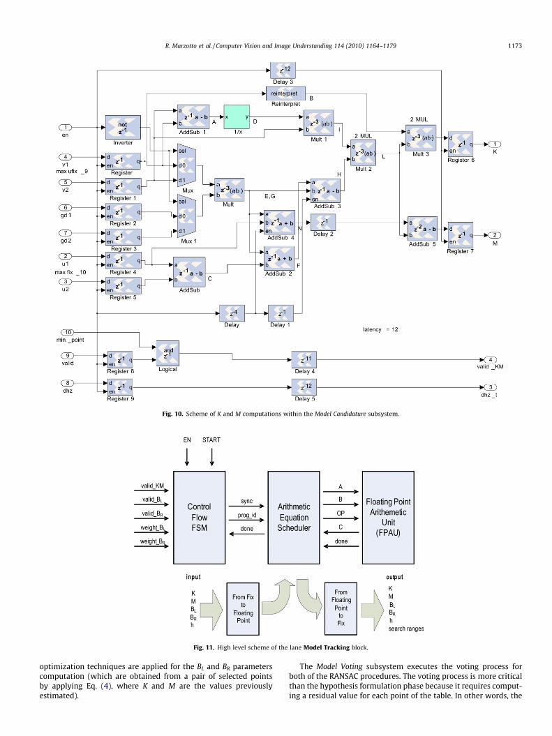
Fig. 10. Scheme of K and M computations within the Model Candidature subsystem.
Fig. 11. High level scheme of the lane Model Tracking block.
R. Marzotto et al. / Computer Vision and Image Understanding 114 (2010) 1164–1179 1173
optimization techniques are applied for the BL and BR parameterscomputation (which are obtained from a pair of selected pointsby applying Eq. (4), where K and M are the values previouslyestimated).
The Model Voting subsystem executes the voting process forboth of the RANSAC procedures. The voting process is more criticalthan the hypothesis formulation phase because it requires comput-ing a residual value for each point of the table. In other words, the
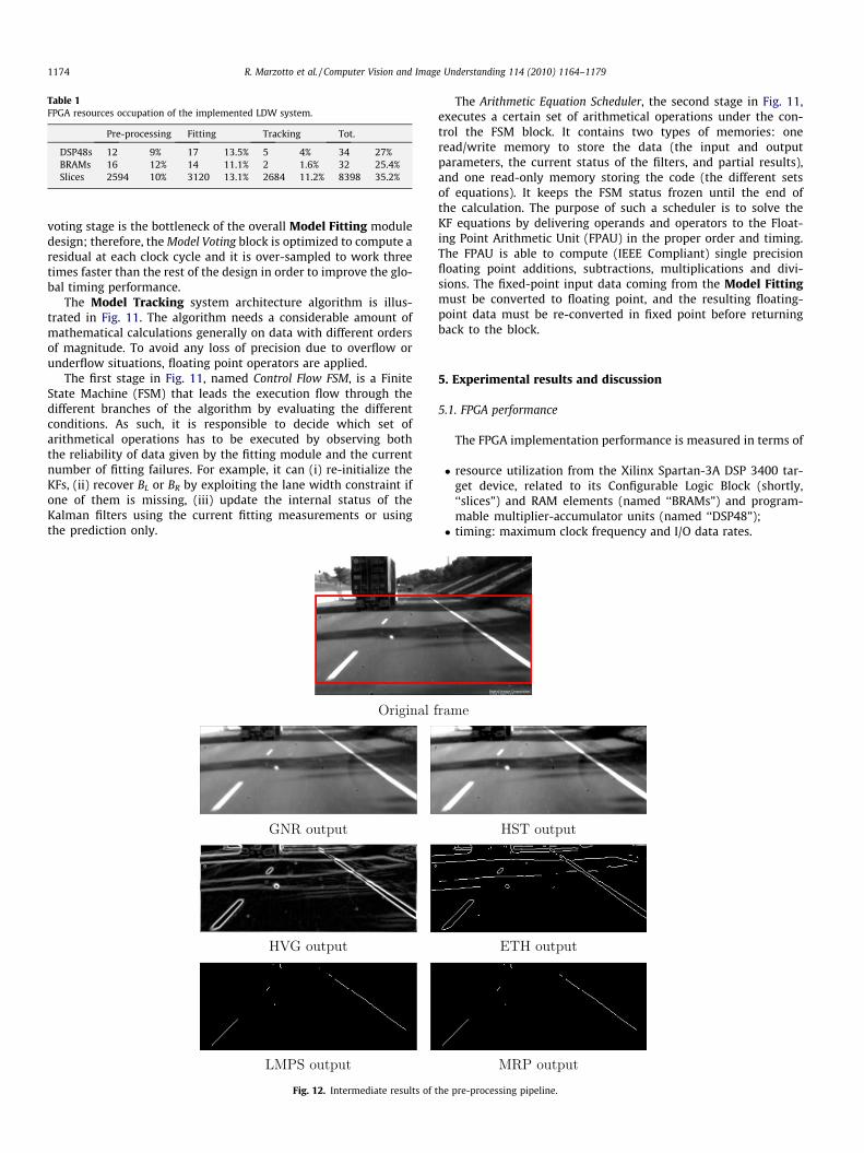
Table 1FPGA resources occupation of the implemented LDW system.
Pre-processing Fitting Tracking Tot.
DSP48s 12 9% 17 13.5% 5 4% 34 27%BRAMs 16 12% 14 11.1% 2 1.6% 32 25.4%Slices 2594 10% 3120 13.1% 2684 11.2% 8398 35.2%
1174 R. Marzotto et al. / Computer Vision and Image Understanding 114 (2010) 1164–1179
voting stage is the bottleneck of the overall Model Fitting moduledesign; therefore, the Model Voting block is optimized to compute aresidual at each clock cycle and it is over-sampled to work threetimes faster than the rest of the design in order to improve the glo-bal timing performance.
The Model Tracking system architecture algorithm is illus-trated in Fig. 11. The algorithm needs a considerable amount ofmathematical calculations generally on data with different ordersof magnitude. To avoid any loss of precision due to overflow orunderflow situations, floating point operators are applied.
The first stage in Fig. 11, named Control Flow FSM, is a FiniteState Machine (FSM) that leads the execution flow through thedifferent branches of the algorithm by evaluating the differentconditions. As such, it is responsible to decide which set ofarithmetical operations has to be executed by observing boththe reliability of data given by the fitting module and the currentnumber of fitting failures. For example, it can (i) re-initialize theKFs, (ii) recover BL or BR by exploiting the lane width constraint ifone of them is missing, (iii) update the internal status of theKalman filters using the current fitting measurements or usingthe prediction only.
Fig. 12. Intermediate results of
The Arithmetic Equation Scheduler, the second stage in Fig. 11,executes a certain set of arithmetical operations under the con-trol the FSM block. It contains two types of memories: oneread/write memory to store the data (the input and outputparameters, the current status of the filters, and partial results),and one read-only memory storing the code (the different setsof equations). It keeps the FSM status frozen until the end ofthe calculation. The purpose of such a scheduler is to solve theKF equations by delivering operands and operators to the Float-ing Point Arithmetic Unit (FPAU) in the proper order and timing.The FPAU is able to compute (IEEE Compliant) single precisionfloating point additions, subtractions, multiplications and divi-sions. The fixed-point input data coming from the Model Fittingmust be converted to floating point, and the resulting floating-point data must be re-converted in fixed point before returningback to the block.
5. Experimental results and discussion
5.1. FPGA performance
The FPGA implementation performance is measured in terms of
� resource utilization from the Xilinx Spartan-3A DSP 3400 tar-get device, related to its Configurable Logic Block (shortly,‘‘slices”) and RAM elements (named ‘‘BRAMs”) and program-mable multiplier-accumulator units (named ‘‘DSP48”);� timing: maximum clock frequency and I/O data rates.
the pre-processing pipeline.
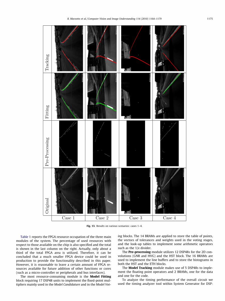
Fig. 13. Results on various scenarios: cases 1–4.
R. Marzotto et al. / Computer Vision and Image Understanding 114 (2010) 1164–1179 1175
Table 1 reports the FPGA resource occupation of the three mainmodules of the system. The percentage of used resources withrespect to those available on the chip is also specified and the totalis shown in the last column on the right. Actually, only about athird of the total FPGA area is utilized. Therefore, it can beconcluded that a much smaller FPGA device could be used inproduction to provide the functionality described in this paper.However, it is reasonable to leave a certain amount of FPGA re-sources available for future addition of other functions or cores(such as a micro-controller or peripherals and bus interfaces).
The most resource-consuming module is the Model Fittingblock requiring 17 DSP48 units to implement the fixed-point mul-tipliers mainly used in the Model Candidature and in the Model Vot-
ing blocks. The 14 BRAMs are applied to store the table of points,the vectors of tolerances and weights used in the voting stages,and the look-up tables to implement some arithmetic operatorssuch as the 1/x divider.
The Pre-processing module utilizes 12 DSP48s for the 2D con-volutions (GNR and HVG) and the HST block. The 16 BRAMs areused to implement the line buffers and to store the histograms inboth the HST and the ETH blocks.
The Model Tracking module makes use of 5 DSP48s to imple-ment the floating point operators and 2 BRAMs, one for the dataand one for the code.
To analyze the timing performance of the overall circuit weused the timing analyzer tool within System Generator for DSP:
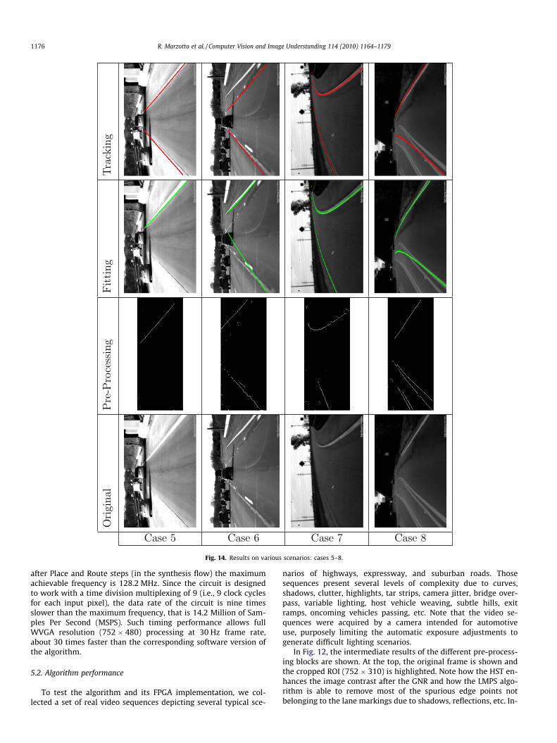
Fig. 14. Results on various scenarios: cases 5–8.
1176 R. Marzotto et al. / Computer Vision and Image Understanding 114 (2010) 1164–1179
after Place and Route steps (in the synthesis flow) the maximumachievable frequency is 128.2 MHz. Since the circuit is designedto work with a time division multiplexing of 9 (i.e., 9 clock cyclesfor each input pixel), the data rate of the circuit is nine timesslower than the maximum frequency, that is 14.2 Million of Sam-ples Per Second (MSPS). Such timing performance allows fullWVGA resolution (752 � 480) processing at 30 Hz frame rate,about 30 times faster than the corresponding software version ofthe algorithm.
5.2. Algorithm performance
To test the algorithm and its FPGA implementation, we col-lected a set of real video sequences depicting several typical sce-
narios of highways, expressway, and suburban roads. Thosesequences present several levels of complexity due to curves,shadows, clutter, highlights, tar strips, camera jitter, bridge over-pass, variable lighting, host vehicle weaving, subtle hills, exitramps, oncoming vehicles passing, etc. Note that the video se-quences were acquired by a camera intended for automotiveuse, purposely limiting the automatic exposure adjustments togenerate difficult lighting scenarios.
In Fig. 12, the intermediate results of the different pre-process-ing blocks are shown. At the top, the original frame is shown andthe cropped ROI (752 � 310) is highlighted. Note how the HST en-hances the image contrast after the GNR and how the LMPS algo-rithm is able to remove most of the spurious edge points notbelonging to the lane markings due to shadows, reflections, etc. In-
50 100 150 200 250−1000
−500
0
500
1000K
50 100 150 200 250−50
0
50M
50 100 150 200 250−1.5
−1
−0.5BL
50 100 150 200 2500.5
1
1.5BR
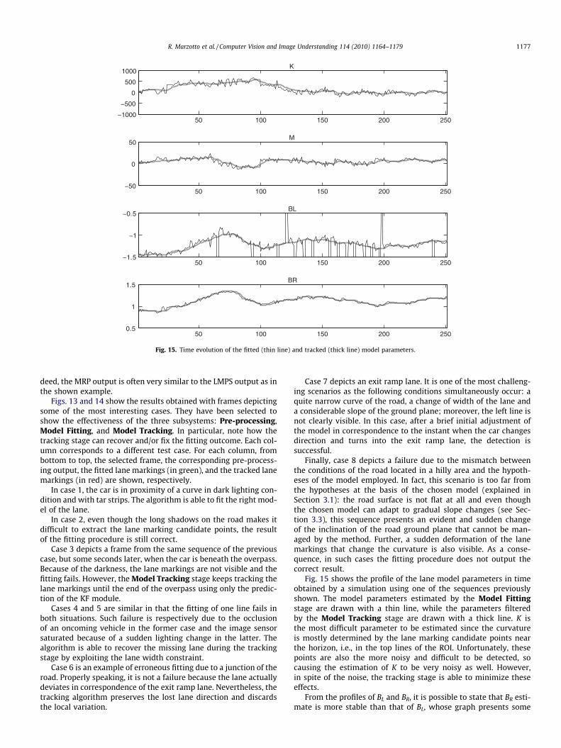
Fig. 15. Time evolution of the fitted (thin line) and tracked (thick line) model parameters.
R. Marzotto et al. / Computer Vision and Image Understanding 114 (2010) 1164–1179 1177
deed, the MRP output is often very similar to the LMPS output as inthe shown example.
Figs. 13 and 14 show the results obtained with frames depictingsome of the most interesting cases. They have been selected toshow the effectiveness of the three subsystems: Pre-processing,Model Fitting, and Model Tracking. In particular, note how thetracking stage can recover and/or fix the fitting outcome. Each col-umn corresponds to a different test case. For each column, frombottom to top, the selected frame, the corresponding pre-process-ing output, the fitted lane markings (in green), and the tracked lanemarkings (in red) are shown, respectively.
In case 1, the car is in proximity of a curve in dark lighting con-dition and with tar strips. The algorithm is able to fit the right mod-el of the lane.
In case 2, even though the long shadows on the road makes itdifficult to extract the lane marking candidate points, the resultof the fitting procedure is still correct.
Case 3 depicts a frame from the same sequence of the previouscase, but some seconds later, when the car is beneath the overpass.Because of the darkness, the lane markings are not visible and thefitting fails. However, the Model Tracking stage keeps tracking thelane markings until the end of the overpass using only the predic-tion of the KF module.
Cases 4 and 5 are similar in that the fitting of one line fails inboth situations. Such failure is respectively due to the occlusionof an oncoming vehicle in the former case and the image sensorsaturated because of a sudden lighting change in the latter. Thealgorithm is able to recover the missing lane during the trackingstage by exploiting the lane width constraint.
Case 6 is an example of erroneous fitting due to a junction of theroad. Properly speaking, it is not a failure because the lane actuallydeviates in correspondence of the exit ramp lane. Nevertheless, thetracking algorithm preserves the lost lane direction and discardsthe local variation.
Case 7 depicts an exit ramp lane. It is one of the most challeng-ing scenarios as the following conditions simultaneously occur: aquite narrow curve of the road, a change of width of the lane anda considerable slope of the ground plane; moreover, the left line isnot clearly visible. In this case, after a brief initial adjustment ofthe model in correspondence to the instant when the car changesdirection and turns into the exit ramp lane, the detection issuccessful.
Finally, case 8 depicts a failure due to the mismatch betweenthe conditions of the road located in a hilly area and the hypoth-eses of the model employed. In fact, this scenario is too far fromthe hypotheses at the basis of the chosen model (explained inSection 3.1): the road surface is not flat at all and even thoughthe chosen model can adapt to gradual slope changes (see Sec-tion 3.3), this sequence presents an evident and sudden changeof the inclination of the road ground plane that cannot be man-aged by the method. Further, a sudden deformation of the lanemarkings that change the curvature is also visible. As a conse-quence, in such cases the fitting procedure does not output thecorrect result.
Fig. 15 shows the profile of the lane model parameters in timeobtained by a simulation using one of the sequences previouslyshown. The model parameters estimated by the Model Fittingstage are drawn with a thin line, while the parameters filteredby the Model Tracking stage are drawn with a thick line. K isthe most difficult parameter to be estimated since the curvatureis mostly determined by the lane marking candidate points nearthe horizon, i.e., in the top lines of the ROI. Unfortunately, thesepoints are also the more noisy and difficult to be detected, socausing the estimation of K to be very noisy as well. However,in spite of the noise, the tracking stage is able to minimize theseeffects.
From the profiles of BL and BR, it is possible to state that BR esti-mate is more stable than that of BL, whose graph presents some
1178 R. Marzotto et al. / Computer Vision and Image Understanding 114 (2010) 1164–1179
spikes in the measurement trend. This behavior is likely due to thepresence of a dashed line in the left lane. Actually, because of thedisconnected segments, there are frames where no lane markersare present, and even when the line segment is visible, lane mark-ing points are very few as compared to those of a solid line. Even inthis case, the tracking algorithm successfully fills these gaps andrecovers the missing line by exploiting the presence of the otherline and the lane width constraint.
Although Figs. 12–14 report necessarily only 1 frame, the testwas exhaustively done on the whole sequences using the FPGAdevelopment board of the Spartan-3A 3400 DSP device [31], in par-ticular in the so called Ethernet point-to-point hardware-softwareco-simulation, a procedure allowed only by System Generator forDSP. The tool, transparently to the user, creates the Ethernet infra-structure communication between the Simulink environment run-ning on the host PC and the FPGA target device placed on theboard. The host PC transmits the frames from the video sequenceto the FPGA device via shared memories, thus allowing pseudoreal-time communication during the testing procedure.
In this way, the Ethernet protocol is used only to transfer the in-put video data from the PC side to the hardware platform and totransfer the output results from the hardware platform to the PC.This simulation allows to test the design on the real hardwareand to measure actual performances as the whole processing wason the FPGA. Nevertheless, we recently integrated our design in astand-alone hardware platform directly connected with an auto-motive CMOS camera, and preliminar tests on a real vehicle pro-vides performances up to 60 fps at VGA resolution.
6. Conclusions
In this paper, a roadway path extraction and tracking algo-rithm is presented. The algorithm is composed of three mainmodules: (1) a pre-processing pipeline devoted to removingnoise, increasing the image quality and extracting the lane mark-ing candidates, (2) a model fitting module that estimates theparameters of the parabolic road model using a RANSAC-likealgorithm, and (3) a stage to track the model parameters for amore stable and reliable operation. No camera calibration is re-quired, and this makes the method suitable to be implementedmore easily in real applications.
A prototype has been implemented on a Spartan-3A DSP 3400FPGA device. The design consumes about 30% of the FPGA hard-ware resources and runs in real-time at a 30 Hz frame rate withWVGA image resolution. To the best of the authors’ knowledge,this is the first time that a complete image/video processing anal-ysis system and its control procedures, are completely imple-mented in an FPGA as a pipeline of specialized modules.
Results have been provided using real and challenging roadsequences of different complexities collected by an onboard auto-motive camera, and have shown that the method has good perfor-mance in terms of both image quality and numerical accuracy.The restrictions of the system reside mainly in the limits of the roadmodel employed and on the complexity of certain type of roads,which do not allow the extraction of road boundaries or to reliablyrecover model parameters.
The FPGA prototype can be considered as a good starting point fora deployable off-the-shelf core for LDW systems due to the robustand stable performances under various roadway conditions.
Future work will be devoted to improving the tracking phasewhich can be made more effective to manage critical situations,changing the Kalman framework into a particle filter-basedmethod, and extending the validation phase by extensively test-ing the proposed method on a car equipped by a camera directlylinked to the proposed system prototype. The system will be
completed by adding a warning module based on the modelparameters check. Finally, a repartitioning of all the includedfunctions between the FPGA fabric and an on-chip serial proces-sor will also be considered to provide the best optimal FPGA-based implementation.
References
[1] D. Bagni, R. Marzotto, P. Zoratti, Building automotive driver assistancesystem algorithms with Xilinx FPGA, Xilinx Xcell Journal (Fourth quarter)(2008) 20–26.
[2] D. Bagni, P. Zoratti, Block matching for automotive applications on Spartan-3ADSP devices, Xilinx Xcell Journal (First quarter) (2008) 16–19.
[3] P. Abusaidi, M. Klein, B. Philofsky, Virtex-5 FPGA system power designconsiderations, Xilinx White Paper WP285 (v1.0), February 14, 2008.
[4] M. Santarini, Driver assistance revs up on Xilinx FPGA platforms, Xilinx XcellJournal (Fourth quarter) (2008) 8–15.
[5] Image-Based Driver Assistance Development Environment, White Paper,Altera Corporation, December 2008 (FPGAs Used in Image-Based DriverAssistance System. Nikkei Electronics Asia, April 2009; <http://techon.nikkeibp.co.jp/article/HONSHI/20090327/167919/>).
[6] M. Bertozzi, A. Broggi, GOLD: a parallel real-time stereo vision system forgeneric obstacle and lane detection, in: IEEE Transaction on Image Processing,1998, pp. 62–81.
[7] J. Goldbeck, B. Huertgen, Lane detection and tracking by video sensors, in:Proceedings of the IEEE/IEEJ/JSAI International Conference on IntelligentTransportation Systems, 1999, pp. 74–79.
[8] M. Beauvais, S. Lakshmanan, CLARK: a heterogeneous sensor fusion method forfinding lanes and obstacles, Image and Vision Computing 18 (5) (2000) 397–413.
[9] A.H.S. Lai, N.H.C. Yung, Lane detection by orientation and lengthdiscrimination, IEEE Transactions on Systems, Man, and Cybernetics, Part B30 (4) (2000) 539–548.
[10] J.B. McDonald, Application of the hough transform to lane detection andfollowing on high speed roads, in: Proceedings of the Irish Machine Vision andImage Processing Conference, 2001.
[11] Y. Wang, E.K. Teoh, D. Shen, Lane detection and tracking using B-snake, Imageand Vision Computing Journal 22 (4) (2004) 269–280.
[12] Q. Li, N. Zheng, H. Cheng, Springrobot: a prototype autonomous vehicle and itsalgorithms for lane detection, IEEE Transactions on Intelligent TransportationSystems 5 (4) (2004) 300–308.
[13] Y.U. Yim, S.Y. Oh, Three-feature based automatic lane detection algorithm(TFALDA) for autonomous driving, IEEE Transactions on IntelligentTransportation Systems 4 (4) (2003) 219–225.
[14] S. Nedevschi, R. Schmidt, T. Graf, R. Danescu, 3D lane detection system basedon stereovision, in: Proceedings of the IEEE Conference on IntelligentTransportation Systems, 2004, pp. 161–166.
[15] K. Macek, B. Williams, S. Kolski, R. Siegwart, A lane detection vision module fordriver assistance, in: Proceedings of the IEEE/APS Conference on Mechatronicsand Robotics, 2004.
[16] K. Huh, J. Park, D. Hong, D.D. Cho, J.H. Park, Development of a vision-based lanedetection system considering configuration aspects, Optics and Lasers inEngineering 43 (11) (2005) 1193–1213.
[17] J. Kaszubiak, M. Tornow, R.W. Kuhn, B. Michaelis, C. Knoeppel, Real-timevehicle and lane detection with embedded hardware, in: Proceedings of theIEEE Intelligent Vehicles Symposium, 2005, pp. 619–624.
[18] D. Schreiber, B. Alefs, M. Clabian, Single camera lane detection and tracking, in:Proceedings of the IEEE Conference on Intelligent Transportation Systems,2005, pp. 1114–1119.
[19] J.C. McCall, M.M. Trivedi, Video-based lane estimation and tracking for driverassistance: survey, system, and evaluation, IEEE Transactions on IntelligentTransportation Systems 7 (1) (2006) 20–37.
[20] Y. Zhou, R. Xu, X. Hu, Q. Ye, A robust lane detection and tracking method basedon computer vision, Measurement Science and Technology 17 (4) (2006)736–745.
[21] H. Wang, Q. Chen, Real-time lane detection in various conditions and nightcases, in: Intelligent Transportation Systems Conference, 2006, pp. 1226–1231.
[22] M. Tian, F. Liu, Z. Hu, Single camera 3D lane detection and tracking based onEKF for urban intelligent vehicle, in: Proceedings of the IEEE InternationalConference on Vehicular Electronics and Safety (ICVES 2006), 2006, pp.413–418.
[23] H.Y. Cheng, B.S. Jeng, P.T. Tseng, K.C. Fan, Lane detection with moving vehiclesin the traffic scenes, IEEE Transactions on Intelligent Transportation Systems 7(4) (2006) 571–582.
[24] F. Samadzadegan, A. Sarafraz, M. Tabibi, Automatic lane detection inimage sequences for vision-based navigation purpose, in: Proceedings ofthe ISPRS Commission V Symposium ‘‘Image Engineering and VisionMetrology”, 2006.
[25] Z. Kim, Realtime lane tracking of curved local road, in: Proceedings of the IEEEIntelligent Transportation Systems Conference (ITSC 2006), 2006, pp.1149–1155.
[26] S. Nedevschi, R. Danescu, T. Marita, F. Oniga, C. Pocol, S. Sobol, C. Tomiuc, C.Vancea, M.M. Meinecke, T. Graf, T.B. To, M.A. Obojski, A sensor for urban

R. Marzotto et al. / Computer Vision and Image Understanding 114 (2010) 1164–1179 1179
driving assistance systems based on dense stereovision, in: Proceedings of theIEEE Intelligent Vehicles Symposium, 2007, pp. 276–283.
[27] K. Kluge, Extracting road curvature and orientation from image edge pointswithout perceptual grouping into features, in: Proceedings of IEEE IntelligentVehicles ’94 Symposium, 1994, pp. 109–114.
[28] L. Xu, E. Oja, Randomized hough transform (RHT): basic mechanisms,algorithms, and computational complexities, CVGIP: Image Understanding57 (2) (1993) 131–154.
[29] M.A. Fischler, R.C. Bolles, Random sample consensus: a paradigm for modelfitting with applications to image analysis and automated cartography,Communications of the ACM 24 (1981) 381–395.
[30] Y. Bar-Shalom, T.E. Fortmann, Tracking and data association, Mathematics inScience and Engineering, vol. 179, Academic Press Professional, Inc., San Diego,CA, USA, 1987.
[31] T. Hill, Accelerating video development on FPGAs using the Xilinx XtremeDSPvideo starter kit, Xilinx Xcell Journal (Second quarter) (2008) 52–54.
[32] P-Y. Hsiao, C-W. Yeh, S-S. Huang, L-C. Fu, A portable vision-based real-timelane departure warning system: day and night, IEEE Transactions on VehicularTechnology 58 (4) (2009) 2089–2094.
[33] S. Vitabile, S. Bono, F. Sorbello, An embedded real-time lane-keeper forautomatic vehicle driving, in: International Conference on Complex, Intelligentand Software Intensive Systems, 2008, pp. 279–285.
Related Documents