JOURNAL OF L A T E X CLASS FILES, VOL. X, NO. X, JANUARY 2009 1 12345

Welcome message from author
This document is posted to help you gain knowledge. Please leave a comment to let me know what you think about it! Share it to your friends and learn new things together.
Transcript

JOURNAL OF LATEX CLASS FILES, VOL. X, NO. X, JANUARY 2009 1
1 2 3 4 5
JOURNAL OF LATEX CLASS FILES, VOL. X, NO. X, JANUARY 2009 2
A reactive robotized interface for lower limbrehabilitation: clinical resultsLudovic Saint-Bauzel*, Viviane Pasqui* and Isabelle Monteil**
Abstract—This article presents clinical results from the useof MONIMAD, a reactive robotized interface for lower limbRehabilitation of patients suffering from cerebellar disease. Thefirst problem to be addressed is the postural analysis of sit-to-stand motion. Experiments with healthy subjects were performedfor this purpose. Analysis of external forces shows that sit-to-stand transfer can be subdivided into several phases: preaccel-eration, acceleration, start rising, rising. Observationof Centerof Pressure, ground forces and horizontal components forceonhandles yields rules to identify the stability of the patient andto adjust the robotic interface motion to the human voluntarymovement. These rules are used in a fuzzy-based controllerimplementation. The controller is validated on experiments withdiseased patients in Bellan Hospital.
Index Terms—Physical Human-Robot Interaction ;Rehabilitation ; Assistive device ; Robotic interface ; Humancentered robotic ; Postural stability ; Sit-to-stand ; Fuzzycontrol.
I. I NTRODUCTION
REHABILITATION involves the management of disordersthat alter the function and the performance of patients.
Rehabilitation is in essence a combination of medication, phys-ical manipulation, therapeutic exercises adapted to technicalaids. In the case of rehabilitation for locomotion, physiothera-pists are confronted to an additional problem: management ofpostural balance. Several persons are then needed to maintainquite at the same time the person in standing up posture andmake him/her do therapeutic movements. This supplementarytask is difficult and does not require any medical skills (seeFig. 1, left ).
Fig. 1. Classical gait rehabilitation [1]
e-mail: [email protected], [email protected],[email protected]*ISIR,UPMC-Paris 6**Sainte Marie Hospital, ParisManuscript received 15 september, 2008; revised december 25, 2008.
In addition, postures needed to apply these exercises to apatient are uncomfortable for medical staff (see Fig. 1, right).Consequently, exercises are short in time, a further limitationto the rehabilitation protocols.
Finally, the more time the medical staff spends with apatient, the better the patient is healed but less patients arehealed.
Recently, technological aids and robots have been intro-duced to reduce the number of persons around the patient.
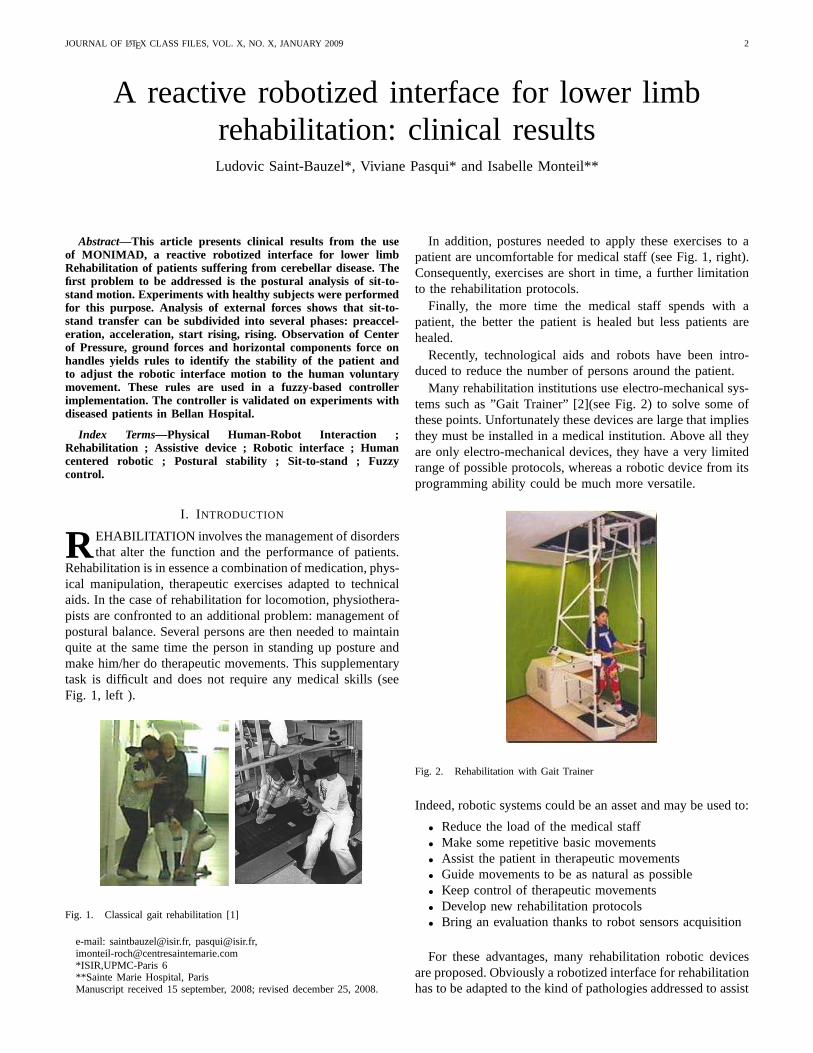
Many rehabilitation institutions use electro-mechanicalsys-tems such as ”Gait Trainer” [2](see Fig. 2) to solve some ofthese points. Unfortunately these devices are large that impliesthey must be installed in a medical institution. Above all theyare only electro-mechanical devices, they have a very limitedrange of possible protocols, whereas a robotic device from itsprogramming ability could be much more versatile.
Fig. 2. Rehabilitation with Gait Trainer
Indeed, robotic systems could be an asset and may be used to:
• Reduce the load of the medical staff• Make some repetitive basic movements• Assist the patient in therapeutic movements• Guide movements to be as natural as possible• Keep control of therapeutic movements• Develop new rehabilitation protocols• Bring an evaluation thanks to robot sensors acquisition
For these advantages, many rehabilitation robotic devicesare proposed. Obviously a robotized interface for rehabilitationhas to be adapted to the kind of pathologies addressed to assist
JOURNAL OF LATEX CLASS FILES, VOL. X, NO. X, JANUARY 2009 3
the patient and to make him/her ”work” to reduce effects ofhis/her disease.
In some pathologies (multi-sclerosis, postfall syndrome,etc.), recovery of the locomotion is possible if someone walkswith the patient. These pathologies affect postural balance andconsequently lead to many difficulties during both sit-to-standtransfer and walking actions. In these cases, it is necessary tosupport the balance. This support can be a first requirementto involve rehabilitation. In these conditions, it is important tochoose a solution that can be used in daily life and that is ableto help the patient during gait and sit-to-stand. Currently, whenthe locomotion exists but is deficient, the most used technicalaid is the zimmer frame. Such a mechanical system, improvedby advanced robotics techniques in order to reinforce walkingin safe conditions, could address many diseases or deficiencies.
Concerning rehabilitation of lower limbs, the most commonexercises are addressing locomotor system training. Theseex-ercises are used to train upright posture and walking movementand paraplegia patients are often the aim of this therapy.
The robotized solutions for those exercises consist in onehand of a body harness supporting the patient’s weight and onthe other hand of a robotized interface in contact with lowerlimbs to make him/her walk.
A first kind of such solutions is based on an exoskeletonstructure, existing solutions are Lokomat [3], and also Au-toAmbulator [4] or PAM/POGO [5]. They are mechanicallydesigned to follow many parts of the body. They bring someasset in guiding. The walking is trained but exoskeletonsolutions need too much power to be embedded so that thepatient is walking on a threadmill and his motion is guidedby the robot. This solution is safe but can only be used ina clinical environment. For the same reason, a device likeHapticWalker [6] that is totally different in its design is notsuitable. It can only move the feet of the patient. Its mechanicaldesign is based on an analysis of operational space of the feetconsidered as end effectors that the robot must be able tofollow. A weight support is included in the system and it isable to propose some motions of daily life like climbing stairs,walking... Those solutions are real clinical aid but due to theirgreat size, they are not suitable for a daily home training.So they are more used for patient that need to recover basicmovements. Their lack of mobility does not permit to makedaily home reinforcement rehabilitation exercises.
Adapted robotized interfaces like KineAssist [7] or WHERE[8] can help patients that need to walk and to have a weightysupport. However, when the patient is still strong enough tosupport his/her body, it is not suitable to use a harness, thatcan lead to a loose of muscular strength.
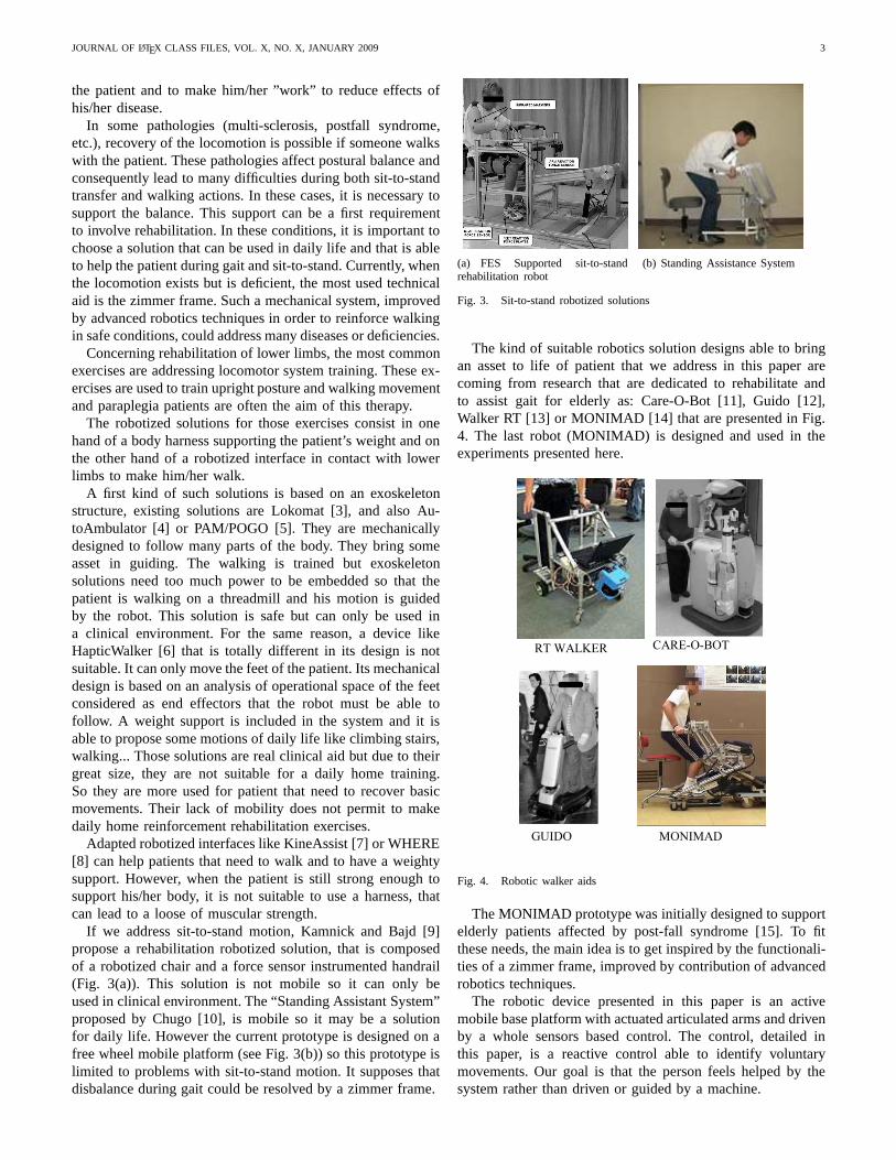
If we address sit-to-stand motion, Kamnick and Bajd [9]propose a rehabilitation robotized solution, that is composedof a robotized chair and a force sensor instrumented handrail(Fig. 3(a)). This solution is not mobile so it can only beused in clinical environment. The “Standing Assistant System”proposed by Chugo [10], is mobile so it may be a solutionfor daily life. However the current prototype is designed onafree wheel mobile platform (see Fig. 3(b)) so this prototypeislimited to problems with sit-to-stand motion. It supposes thatdisbalance during gait could be resolved by a zimmer frame.
(a) FES Supported sit-to-standrehabilitation robot
(b) Standing Assistance System
Fig. 3. Sit-to-stand robotized solutions
The kind of suitable robotics solution designs able to bringan asset to life of patient that we address in this paper arecoming from research that are dedicated to rehabilitate andto assist gait for elderly as: Care-O-Bot [11], Guido [12],Walker RT [13] or MONIMAD [14] that are presented in Fig.4. The last robot (MONIMAD) is designed and used in theexperiments presented here.
Fig. 4. Robotic walker aids
The MONIMAD prototype was initially designed to supportelderly patients affected by post-fall syndrome [15]. To fitthese needs, the main idea is to get inspired by the functionali-ties of a zimmer frame, improved by contribution of advancedrobotics techniques.
The robotic device presented in this paper is an activemobile base platform with actuated articulated arms and drivenby a whole sensors based control. The control, detailed inthis paper, is a reactive control able to identify voluntarymovements. Our goal is that the person feels helped by thesystem rather than driven or guided by a machine.
JOURNAL OF LATEX CLASS FILES, VOL. X, NO. X, JANUARY 2009 4
A particularity of this work is that it is centered on helpingpeople. The patient is not considered in the control as a masternor a slave of the robot. Patients do exercises with the robotin a way that the support of the machine feels transparent.This aim is achieved by the use of a fuzzy-logic based controlthat works from an immediate and natural handling of therobot, not a control based on a box with buttons or particulargesture to control the device. Furthermore, assistance mustbegin from the sit gesture, with as few preparation as possibleto use the robotized interface.The MONIMAD prototype (see Fig. 5) is evaluated in arehabilitation hospital specialised in the case of multi-sclerosisdiseased patients who are often affected by cerebellar ataxia,a disease that leads to trouble in balance during sit-to-standand walking gestures.
Fig. 5. The MONIMAD Prototype
The aim of this paper is to present experiments withMONIMAD used by patient to stand-up, and to study thelearning rate of the device. Section II explains the mechanicalstructure of the MONIMAD prototype and the implementedcontrol that brings reactivity to the robot. In section III,wedescribe the experimental protocol worked out by the medicalstaff. Then, section IV is dedicated to the discussion on thepros and cons of both our method and our experiments.
II. M ATERIAL AND METHODS
The aim of the MONIMAD prototype is to help peoplewithout human assistance. This work is driven by the PhysicalHuman-Robot Interaction in mechanical design and in controldesign. The design of this solution can be divided in two mainparts:
• the assistive robot with its mechanical characteristics,• the control that makes the robot actions intuitive and safe
for patients.
A particularity of this work is that it is centered on helpingpeople. The role of the patient in the control is neither to bea master nor a slave of the robot but a few of each.
A. Mechanical design
The detailed mechanical design method is described in[16]. The main idea of the design is to place natural ac-tions addressed above as the main requirement. The designed
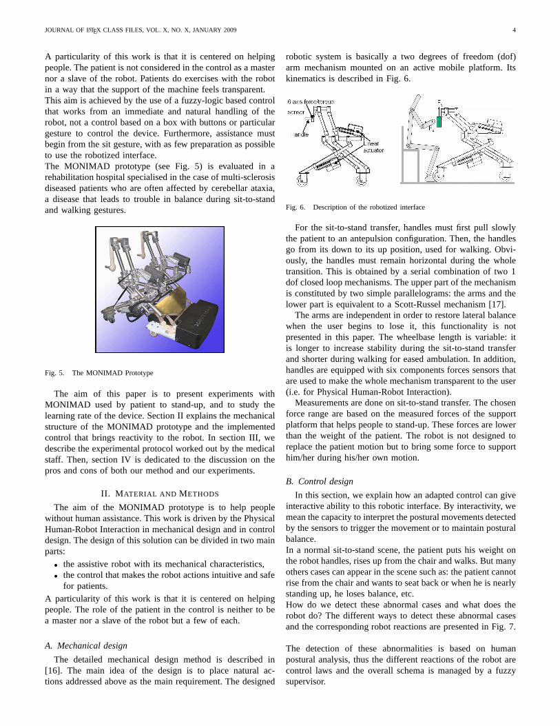
robotic system is basically a two degrees of freedom (dof)arm mechanism mounted on an active mobile platform. Itskinematics is described in Fig. 6.
Fig. 6. Description of the robotized interface
For the sit-to-stand transfer, handles must first pull slowlythe patient to an antepulsion configuration. Then, the handlesgo from its down to its up position, used for walking. Obvi-ously, the handles must remain horizontal during the wholetransition. This is obtained by a serial combination of two 1dof closed loop mechanisms. The upper part of the mechanismis constituted by two simple parallelograms: the arms and thelower part is equivalent to a Scott-Russel mechanism [17].
The arms are independent in order to restore lateral balancewhen the user begins to lose it, this functionality is notpresented in this paper. The wheelbase length is variable: itis longer to increase stability during the sit-to-stand transferand shorter during walking for eased ambulation. In addition,handles are equipped with six components forces sensors thatare used to make the whole mechanism transparent to the user(i.e. for Physical Human-Robot Interaction).
Measurements are done on sit-to-stand transfer. The chosenforce range are based on the measured forces of the supportplatform that helps people to stand-up. These forces are lowerthan the weight of the patient. The robot is not designed toreplace the patient motion but to bring some force to supporthim/her during his/her own motion.
B. Control design
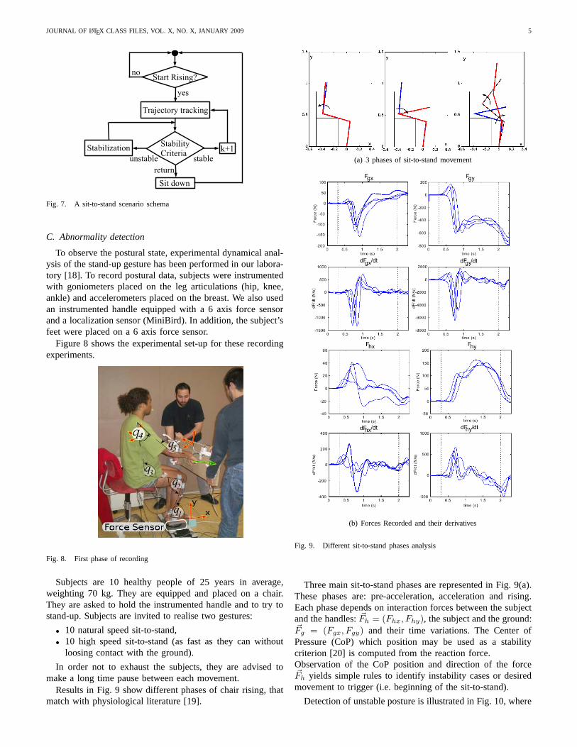
In this section, we explain how an adapted control can giveinteractive ability to this robotic interface. By interactivity, wemean the capacity to interpret the postural movements detectedby the sensors to trigger the movement or to maintain posturalbalance.In a normal sit-to-stand scene, the patient puts his weight onthe robot handles, rises up from the chair and walks. But manyothers cases can appear in the scene such as: the patient cannotrise from the chair and wants to seat back or when he is nearlystanding up, he loses balance, etc.How do we detect these abnormal cases and what does therobot do? The different ways to detect these abnormal casesand the corresponding robot reactions are presented in Fig.7.
The detection of these abnormalities is based on humanpostural analysis, thus the different reactions of the robot arecontrol laws and the overall schema is managed by a fuzzysupervisor.
JOURNAL OF LATEX CLASS FILES, VOL. X, NO. X, JANUARY 2009 5
Fig. 7. A sit-to-stand scenario schema
C. Abnormality detection
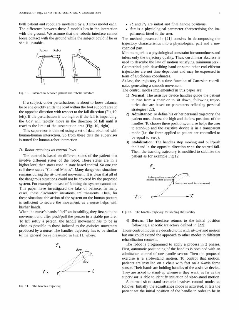
To observe the postural state, experimental dynamical anal-ysis of the stand-up gesture has been performed in our labora-tory [18]. To record postural data, subjects were instrumentedwith goniometers placed on the leg articulations (hip, knee,ankle) and accelerometers placed on the breast. We also usedan instrumented handle equipped with a 6 axis force sensorand a localization sensor (MiniBird). In addition, the subject’sfeet were placed on a 6 axis force sensor.
Figure 8 shows the experimental set-up for these recordingexperiments.
Fig. 8. First phase of recording
Subjects are 10 healthy people of 25 years in average,weighting 70 kg. They are equipped and placed on a chair.They are asked to hold the instrumented handle and to try tostand-up. Subjects are invited to realise two gestures:
• 10 natural speed sit-to-stand,• 10 high speed sit-to-stand (as fast as they can without
loosing contact with the ground).
In order not to exhaust the subjects, they are advised tomake a long time pause between each movement.
Results in Fig. 9 show different phases of chair rising, thatmatch with physiological literature [19].
(a) 3 phases of sit-to-stand movement
(b) Forces Recorded and their derivatives
Fig. 9. Different sit-to-stand phases analysis
Three main sit-to-stand phases are represented in Fig. 9(a).These phases are: pre-acceleration, acceleration and rising.Each phase depends on interaction forces between the subjectand the handles:~Fh = (Fhx, Fhy), the subject and the ground:~Fg = (Fgx, Fgy) and their time variations. The Center ofPressure (CoP) which position may be used as a stabilitycriterion [20] is computed from the reaction force.Observation of the CoP position and direction of the force~Fh yields simple rules to identify instability cases or desiredmovement to trigger (i.e. beginning of the sit-to-stand).
Detection of unstable posture is illustrated in Fig. 10, where
JOURNAL OF LATEX CLASS FILES, VOL. X, NO. X, JANUARY 2009 6
both patient and robot are modelled by a 3 links model each.The difference between these 2 models lies in the interactionwith the ground. We assume that the robotic interface cannotloose contact with the ground while the subject could if he orshe is unstable.
Fig. 10. Interaction between patient and robotic interface
If a subject, under perturbations, is about to loose balance,he or she quickly shifts the load within the foot support areainthe opposite direction with respect to the fall direction (Fig.10.left). If the perturbation is too high or if the fall is impending,the CoP will rapidly move in the direction of fall until itreaches the limit of the sustentation area (Fig. 10, right).
This supervisor is defined using a set of data obtained withhuman-human interaction. So from these data the supervisoris tuned for human-robot interaction.
D. Robot reactions as control laws
The control is based on different states of the patient thatinvolve different states of the robot. These states are in ahigher level than states used in state based control. So one cancall these states “Control Modes”. Many dangerous situationsremains during the sit-to-stand movement. It is clear that all ofthe dangerous situations could not be covered by the proposedsystem. For example, in case of fainting the system cannot act.This paper have investigated the lake of balance. In manycases, these discomfort situations are transients. Then, forthese situations the action of the system on the human postureis sufficient to secure the movement, as a nurse helps withhis/her hands.When the nurse’s hands ”feel” an instability, they first stopthemovement and after push/pull the person in a stable posture.To lift softly a person, the handle movement has to be asclose as possible to those induced to the assistive movementproduced by a nurse. The handles trajectory has to be similarto the general curve presented in Fig.11, where:
Fig. 11. The handles trajectory
• Pi andPf are initial and final handle positions• dev is a physiological parameter characterising the im-
pairment, fitted to the user.The method presented in [21] consists in decomposing thetrajectory characteristics into a physiological part and ame-chanical part.Minimum jerk is a physiological constraint for smoothness andinfers only the trajectory quality. Thus, curvilinear abscissa isused to describe the law of motion satisfying minimum jerk.Geometrical path describing hand or some other end effectortrajectories are not time dependent and may be expressed interm of Euclidean coordinates.At last, the trajectory is a time function of Cartesian coordi-nates generating a smooth movement.The control modes implemented in this paper are:
1) Normal: The assistive device handles guide the patientto rise from a chair or to sit down, following trajec-tories that are based on parameters reflecting personalstrategies [22].
2) Admittance: To define his or her personal trajectory, thepatient must choose the high and the low positions of thehandles. To choose these positions, a nurse helps the userto stand-up and the assistive device is in a transparentmode (i.e. the force applied to patient are controlled tobe equal to zero).
3) Stabilization: The handles stop moving and pull/pushthe hand in the opposite direction w.r.t. the started fall.Then, the tracking trajectory is modified to stabilize thepatient as for example Fig.12
Fig. 12. The handles trajectory for keeping the stability
4) Return: The interface returns to the initial positionfollowing a specific trajectory defined in [22].
Those control modes are decided to fit with sit-to-stand motionbut one could extend the approach to other modes in differentrehabilitation contexts.
The robot is programmed to apply a process in 2 phases.First, automatic positioning of the handles is obtained with anadmittance control of one handle sensor. Then the proposedexercise is a sit-to-stand motion. To control that motion,patients are installed on a chair with feet on a 6-axis forcesensor. Their hands are holding handles of the assistive device.They are asked to stand-up whenever they want, as far as thesupervisor is able to identify initiation of sit-to-stand motion.
A normal sit-to-stand scenario involves control modes asfollows. Initially the admittance mode is activated, it lets thepatient set the initial position of the handle in order to be in
JOURNAL OF LATEX CLASS FILES, VOL. X, NO. X, JANUARY 2009 7
good position for sit-to-stand motion. After that, theNormalmode is triggered by detection of the pre-acceleration phase.So in that mode, the handlers movement begins to guidethe patient from sit to stand posture. During this sit-to-standmotion, theReturn mode can be activated when an abortingmovement of the patient is identified. In that case, the robotreturns to the initial position.If postural instability is detected, theStabilization mode isthen activated, the vertical motion of the device is stopped,and a new desired position is computed that guaranteespatient stability.
All these control modes are designed with fuzzy logicblocks that identify the postural state of the patient, and putthe robot into the corresponding control mode.
E. Fuzzy supervisor
A fuzzy controller is a good way to design an interactivedevice [23],[24]. Here, we have extended the role of the fuzzysupervisor from the detection of voluntary movements to thedetection of instability.From the set of experimental data, fuzzy logic sets are tunedto have a representative definition of supervisor. The fuzzysupervision has to fulfill two tasks, that define two outputs:
• output 1: recognition of the current phase, resulting inthe choice of control modes 1, 2, 4
• output 2: determination of the proper reaction to ensurestability of the subject, and determine amount of use ofcontrol mode 3.
The fuzzy sets defined for the output 1 are shown in Fig. 13
Fig. 13. Membership functions for output 1
The detection of the phases of the sit-to-stand is obtainedanalyzing the value of the~Fh, ~Fg forces shown in Fig. 9, theirtime variation and computed CoP.
A fuzzy-controller able to represent sit-to-stand transfer isset-up from force information Fig. 9(b) obtained at the handle,force information coming from the ground interaction andspecially computation of the CoP.
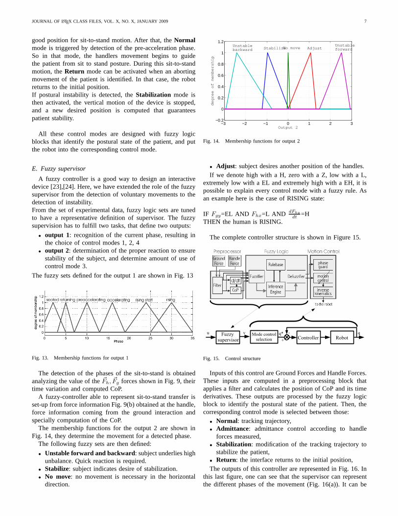
The membership functions for the output 2 are shown inFig. 14, they determine the movement for a detected phase.
The following fuzzy sets are then defined:
• Unstable forward and backward: subject underlies highunbalance. Quick reaction is required.
• Stabilize: subject indicates desire of stabilization.• No move: no movement is necessary in the horizontal
direction.
−3 −2 −1 0 1 2 3−0.2
0
0.2
0.4
0.6
0.8
1
1.2
Output 2
degree of membership
Unstablebackward StabilizeNo move Adjust
Unstableforward
Fig. 14. Membership functions for output 2
• Adjust : subject desires another position of the handles.If we denote high with a H, zero with a Z, low with a L,
extremely low with a EL and extremely high with a EH, it ispossible to explain every control mode with a fuzzy rule. Asan example here is the case of RISING state:
IF Fgy=EL AND Fhx=L AND dFhy
dt=H
THEN the human is RISING.
The complete controller structure is shown in Figure 15.
Fig. 15. Control structure
Inputs of this control are Ground Forces and Handle Forces.These inputs are computed in a preprocessing block thatapplies a filter and calculates the position of CoP and its timederivatives. These outputs are processed by the fuzzy logicblock to identify the postural state of the patient. Then, thecorresponding control mode is selected between those:
• Normal: tracking trajectory,• Admittance: admittance control according to handle
forces measured,• Stabilization: modification of the tracking trajectory to
stabilize the patient,• Return: the interface returns to the initial position,The outputs of this controller are represented in Fig. 16. In
this last figure, one can see that the supervisor can representthe different phases of the movement (Fig. 16(a)). It can be
JOURNAL OF LATEX CLASS FILES, VOL. X, NO. X, JANUARY 2009 8
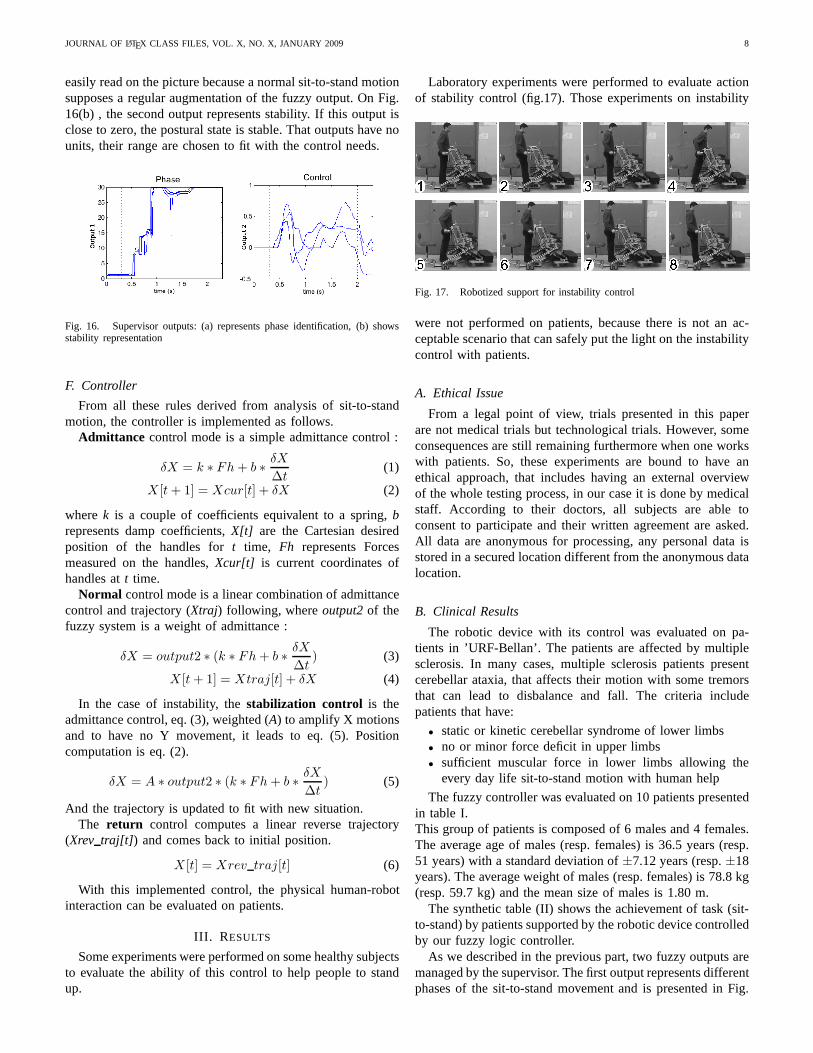
easily read on the picture because a normal sit-to-stand motionsupposes a regular augmentation of the fuzzy output. On Fig.16(b) , the second output represents stability. If this output isclose to zero, the postural state is stable. That outputs have nounits, their range are chosen to fit with the control needs.
Fig. 16. Supervisor outputs: (a) represents phase identification, (b) showsstability representation
F. Controller
From all these rules derived from analysis of sit-to-standmotion, the controller is implemented as follows.
Admittance control mode is a simple admittance control :
δX = k ∗ Fh + b ∗δX
∆t(1)
X [t + 1] = Xcur[t] + δX (2)
wherek is a couple of coefficients equivalent to a spring,brepresents damp coefficients,X[t] are the Cartesian desiredposition of the handles fort time, Fh represents Forcesmeasured on the handles,Xcur[t] is current coordinates ofhandles att time.
Normal control mode is a linear combination of admittancecontrol and trajectory (Xtraj) following, whereoutput2 of thefuzzy system is a weight of admittance :
δX = output2 ∗ (k ∗ Fh + b ∗δX
∆t) (3)
X [t + 1] = Xtraj[t] + δX (4)
In the case of instability, thestabilization control is theadmittance control, eq. (3), weighted (A) to amplify X motionsand to have no Y movement, it leads to eq. (5). Positioncomputation is eq. (2).
δX = A ∗ output2 ∗ (k ∗ Fh + b ∗δX
∆t) (5)
And the trajectory is updated to fit with new situation.The return control computes a linear reverse trajectory
(Xrev traj[t]) and comes back to initial position.
X [t] = Xrev traj[t] (6)
With this implemented control, the physical human-robotinteraction can be evaluated on patients.
III. R ESULTS
Some experiments were performed on some healthy subjectsto evaluate the ability of this control to help people to standup.
Laboratory experiments were performed to evaluate actionof stability control (fig.17). Those experiments on instability
Fig. 17. Robotized support for instability control
were not performed on patients, because there is not an ac-ceptable scenario that can safely put the light on the instabilitycontrol with patients.
A. Ethical Issue
From a legal point of view, trials presented in this paperare not medical trials but technological trials. However, someconsequences are still remaining furthermore when one workswith patients. So, these experiments are bound to have anethical approach, that includes having an external overviewof the whole testing process, in our case it is done by medicalstaff. According to their doctors, all subjects are able toconsent to participate and their written agreement are asked.All data are anonymous for processing, any personal data isstored in a secured location different from the anonymous datalocation.
B. Clinical Results
The robotic device with its control was evaluated on pa-tients in ’URF-Bellan’. The patients are affected by multiplesclerosis. In many cases, multiple sclerosis patients presentcerebellar ataxia, that affects their motion with some tremorsthat can lead to disbalance and fall. The criteria includepatients that have:
• static or kinetic cerebellar syndrome of lower limbs• no or minor force deficit in upper limbs• sufficient muscular force in lower limbs allowing the
every day life sit-to-stand motion with human help
The fuzzy controller was evaluated on 10 patients presentedin table I.This group of patients is composed of 6 males and 4 females.The average age of males (resp. females) is 36.5 years (resp.51 years) with a standard deviation of±7.12 years (resp.±18years). The average weight of males (resp. females) is 78.8 kg(resp. 59.7 kg) and the mean size of males is 1.80 m.
The synthetic table (II) shows the achievement of task (sit-to-stand) by patients supported by the robotic device controlledby our fuzzy logic controller.
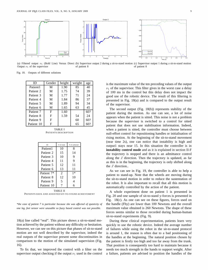
As we described in the previous part, two fuzzy outputs aremanaged by the supervisor. The first output represents differentphases of the sit-to-stand movement and is presented in Fig.
JOURNAL OF LATEX CLASS FILES, VOL. X, NO. X, JANUARY 2009 9
0 1 2 3 4 5 6 70
5
10
15
20
25
30Output 1
Time (s)
Fuz
zy V
alue
RealFiltered
(a) Filtered outputν1 (Bold Line) Versus DirectOutputν1 of the supervisor
0 1 2 3 4 5 6 7−3
−2
−1
0
1
2
3
Time(s)
Fuz
zy V
alue
Output 2
(b) Supervisor output 2 during a sit-to-stand motionof patient 8
0 0.5 1 1.5 2 2.5 3 3.5 4 4.5−600
−500
−400
−300
−200
−100
0
100
Time (s)
Fgy (N)
Fhy (N)
(c) Supervisor output 1 during a sit-to-stand motionof patient 8
Fig. 18. Outputs of different solutions
ID Gender height weight agePatient1 M 1.90 85 40Patient 2 M 1.75 74 39Patient 3 M 1.77 71 24Patient 4 M 1.84 86 37Patient 5 M 1.89 94 34Patient 6 M 1.65 63 45Patient 7 F 1.60 60?Patient 8 F 1.59 54 24Patient 9 F 60 60?Patient 10 F 65 60?
TABLE IPATIENTS DESCRIPTION
ID # of trials # of achieved
Patient1 10 8Patient 2 15 14Patient 3 10 9Patient 4 11 9Patient 5 12 11Patient 6 13 11Patient 7* 2 1*Patient 8 12 10Patient 9 5 4Patient 10 7 6
TABLE IIPATIENTS DATA AND ASSISTED SIT-TO-STAND ACHIEVEMENT
*the case of patient 7 is particular because she was affected of spasticity of
one leg, feet sensor were unusable so fuzzy based control was not possible.
18(a) line called “real”. This picture shows a sit-to-standmo-tion achieved by the patient without any difficulty or hesitation.However, we can see on this picture that phases of sit-to-standmotion are not well described by the supervisor, indeed thereal outputs of the supervisor present some discontinuities incomparison to the motion of the simulated supervision (Fig.16).
To fix that, we improved the control with a filter on thesupervisor output checking if the outputν1 used in the control
is the maximum value of the ten preceding values of the outputν1 of the supervisor. This filter gives in the worst case a delayof 100 ms in the control but this delay does not impact thegood use of the robotic device. The result of this filtering ispresented in Fig. 18(a) and is compared to the output resultof the supervisor.
The second output (Fig. 18(b)) represents stability of thepatient during the motion. As one can see, a lot of noiseappears when the patient is sitted. This noise is not a problembecause the supervisor is switched to a control for sittedpatient that does not use stabilisation information. Indeed,when a patient is sitted, the controller must choose betweennull-effort control for repositioning handles or initialisation ofrising motion. At the beginning of the sit-to-stand movement(near time 2s), one can notice that instability is high andoutput1 stays near 15. In this situation the controller is ininstability control mode and as it is explained in section II-Fthe trajectory is stopped and there is an admittance controlalong the~x direction. Then the trajectory is updated, as faras this is in the beginning, the trajectory is only shifted alongthe ~x direction..
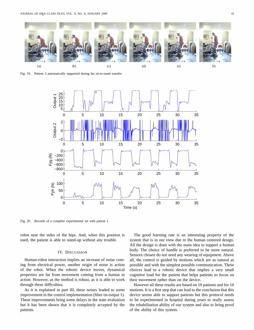
As we can see in Fig. 19, the controller is able to help apatient to stand-up. Note that the wheels are moving duringthe sit-to-stand motion in order to reduce the sustentationofthe robot. It is also important to recall that all this motionisautomatically controlled by the action of the patient.
A whole experiment done on patient 1 is presented inFig. 20 and one sample of sit-to-stand y-forces is presentedinFig. 18(c). As one can see on these figures, forces used onthe handle (Fhy) are lower than 100 Newtons and the overallmaximum value obtained is 260 Newtons. The shape of theseforces seems similar to those recorded during human-humansit-to-stand experiments (Fig. 9).
During these clinical experimentation, patients learn veryquickly to use the robotic device. Indeed the average numberof failures while using the robot in the sit-to-stand protocolis around 1, the reason is often due to a bad positioning ofthe handles at the beginning. The natural position chosen bythe patient is firstly too high and too far away from the trunk.That position is consequently too hard to maintain because itneeds too much strength in the hands to support weight. Aftera failure, patients are advised to position the handles of the
JOURNAL OF LATEX CLASS FILES, VOL. X, NO. X, JANUARY 2009 10
(a) (b) (c) (d) (e) (f)
Fig. 19. Patient 3 automatically supported during his sit-to-stand transfer
0 5 10 15 20 25 30 35
510152025
Out
put 1
0 5 10 15 20 25 30 35−2
0
2
Out
put 2
0 5 10 15 20 25 30 35−800−600−400−200
0
Fyg
(N
)
0 5 10 15 20 25 30 350
50
100
Time (s)
Fyh
(N
)
Fig. 20. Records of a complete experimental set with patient1
robot near the sides of the hips. And, when this position isused, the patient is able to stand-up without any trouble.
IV. D ISCUSSION
Human-robot interaction implies an increase of noise com-ing from electrical power, another origin of noise is actionof the robot. When the robotic device moves, dynamicalproperties are far from movement coming from a human inaction. However, as the method is robust, as it is able to workthrough these difficulties.
As it is explained in part III, these noises leaded to someimprovement in the control implementation (filter on output1).These improvements bring some delays in the state evaluationbut it has been shown that it is completely accepted by thepatients.
The good learning rate is an interesting property of thesystem that is in our view due to the human centered design.All the design is done with the main idea to support a humanbody. The choice of handle is preferred to be more natural.Sensors chosen do not need any wearing of equipment. Aboveall, the control is guided by motions which are as natural aspossible and with the simplest possible communication. Thesechoices lead to a robotic device that implies a very smallcognitive load for the patient that helps patients to focus ontheir movement rather than on the device.
However all these results are based on 10 patients and for 10motions. It is a first step that can lead to the conclusion thatthisdevice seems able to support patients but this protocol needsto be experimented in hospital during years to really assessthe rehabilitation ability of our system and also to bring proofof the ability of this system.
JOURNAL OF LATEX CLASS FILES, VOL. X, NO. X, JANUARY 2009 11
Another limitation of this work is the way fuzzy parametersare tuned. Indeed, tuning is based on a small set of datacoming from healthy subjects. There is room in this part foroptimization on the way these parameters are tuned. In thesame order of idea, it can also be interesting to propose someoptimisation strategies for the whole control tuning.
Finally the use of a ground force sensor becomes a lim-itation when we imagine protocols that combine sit-to-standmotions with walking. We need to develop some solutions thatare able to work without a force sensor under the feet.
V. CONCLUSION
It has been shown in this paper that our rehabilitationrobotics device with its fuzzy based control seems able toassist patients in sit-to-stand motions. The fuzzy-based controlbenefits from using a supervisor in the control to identifystates of the human motion and determine the correspondingbest strategy. This kind of control results in a natural styleof interaction where each partner interacts physically with theother and a common movement emerges from this interaction,that improves the feeling of the patient. This reactive andinteraction based kind of control is a promising approach torehabilitation.
REFERENCES
[1] S. Jezernik, R. Schrer, G. Colombo, and M. Morari, “Adaptive roboticrehabilitation of locomotion: a clinical study in spinallyinjured individ-uals,” Spinal Cord, vol. 41, p. 657666, 2003.
[2] S. Hesse, C. Werner, D. Uhlenbrock, S. Frankenberg, A. Bardeleben,and B. Brandl-Hesse, “An electromechanical gait trainer for restorationof gait in hemiparetic stroke patients: Preliminary results,” NeurorehabilNeural Repair, vol. 15, no. 1, pp. 39–50, 2001.
[3] R. Riener, G. Colombo, and L. Lunenburge, “Overview of robot-aided gait biofeedback and assessment,” inThe First IEEE/RAS-EMBSInternational Conference on Biomedical Robotics and Biomechatronics,february 2006, pp. 965– 970.
[4] J. Kathryn and M. Syranosian, “Autoambulator im-proves functionality for healthsouth’s rehab patients,”http://www.braintreerehabhospital.com/pdf/autoambulator MDNews.pdf.
[5] J. Galvez and D. Reinkensmeyer, “Robotics for gait training after spinalcord injury,” ord Inj Rehabil, vol. 11, no. 2, pp. 18–33, 2005.
[6] H. Schmidt, S. Hesse, R. Bernhardt, and J. Kruger, “”hapticwalker - anovel haptic foot device”,”ACM Transactions on Applied Perception,vol. 2, pp. 166–180, 2005.
[7] M. Peshkin, D. A. Brown, J. J. Santos-Munne, A. Makhlin,E. Lewis,J. Colgate, J. Patton, and D. Schwandt, “Kineassist: A robotic over-ground gait and balance training device,” inroceedings of the 2005IEEE 9th International Conference on Rehabilitation Robotics, June 28- July 1 2005, pp. 241–246.
[8] C. Lee, K. Kim, S. Oh, and J. Lee, “A system for gait rehabilitation:mobile manipulator approach,” inIEEE Int. Conference on Robotics andAutomation, Washington, USA, 2002, pp. 3254–3259.
[9] R. Kamnik and T. Bajd, “Standing-up robot: an assistive rehabilitativedevice for training and assessment,”Journal of Medical Engineeringand Technology, vol. 28, no. 2, p. 7480, march-april 2004.
[10] D. Chugo, W. Matsuoka, S. Jia, and K. Takase, “Rehabilitation walkersystem for standing-up motion,”Proc. of 2007 IEEE/RSJ InternationalConference on Intelligent Robots and Systems, 2007.
[11] B. Graf, “Reactive navigation of an intelligent robotic walking aid,” inProceedings of the IEEE International Workshop on Robot and HumanInteraction: RO-MAN 2001, Bordeaux-Paris, France, 2001, pp. 353–358.
[12] D. Rodriguez-Losada, F. Matia, A. Jimenez, and G. Galan, R.and Lacey,“Implementing map based navigation in guido, the robotic smart walker,”in IEEE International Conference on Robotics and Automation, ICRA’05, Barcelona, Spain, 2005, pp. 3401–3406.
[13] Y. Hirata, A. Hara, and K. Kosuge, “Passive-type intelligent walkingsupport system rt walker,” inProceedings of 2004 1EEElRS.J Inter-national Conference on Intelligent Robots and Systems, September 28.October 2 2004, pp. 4303–4305.
[14] P. Mederic, V. Pasqui, F. Plumet, P. Bidaud, and J. Guinot, “Elderlypeople sit to stand transfer experimental analysis,” in8th Int. Conferenceon Climbing on Walking Robots (CLAWAR’04), London, England, 2005,pp. 953–960.
[15] P. Mederic, J. Lozada, V. Pasqui, F. Plumet, P. Bidaud, and J. Guinot, “Anoptimized design for an intelligent walking-aid,” in6th Int. Conferenceon Climbing on Walking Robots (CLAWAR’03), Catania, Italy, 2003, pp.53–60.
[16] P. Mederic, V. Pasqui, F. Plumet, P. Bidaud, and J. Guinot, “Design of awalking-aid and sit-to-stand transfer assisting device for elderly people,”in 7th Int. Conference on Climbing on Walking Robots (CLAWAR’04),Madrid, Spain, 2004.
[17] H. Chang and Y. Wang, “Design and performance of a piezoelectricactuated precise rotary positioner,”Proceedings on IEEE InternationalConference on Mechatronics, pp. 313–317, 2005.
[18] V. Pasqui, L. Saint-Bauzel, and P. Bidaud, “Postural stability controlfor robot-human cooperation for sit-to-stand assistance.” in Proceedingsof the 10th International Conference on Climbing and Walking Robots,2007, pp. 409–416.
[19] R. Aissaoui and J. Dansereau, “Biomechanical analysisand modellingof sit to stand task: a literature review,” inIEEE International conferenceon systems, man and cybernetics, vol. 1, 1999, pp. 141–146.
[20] P. Sardain and G. Bessonnet, “Forces acting on a biped robot. center ofpressure-zero moment point,”IEEE Transactions on Systems, Man, andCybernetics, Part A: Systemsand Humans, vol. 34, no. 5, pp. 630 – 637,September 2004.
[21] V. Pasqui and P. Bidaud, “Natural trajectory generation for guided armmovement during assisted sit-to-stand transfer.” Brussels, Belgium: 9thInt. Conf. on Climbing and Walking Robots, 2006, pp. 246–251.
[22] P. Mederic, “Conception et commande d’un systeme robotiqued’assistance a la verticalisation et a la deambulation,” Ph.D. dissertation,Universite Pierre et Marie Curie-Paris06, 11 Dec. 2006.
[23] B. KenKnight, R. Sweeney, J. Stahmann, and S. Girouard,“Cardiacrhythm management systems and methods predicting congestive heartfailure status,”US Patent 7 127 290, 2006.
[24] S. Hussein and M. Granat, “Intention detection using a neuro-fuzzyEMG classifier,”Engineering in Medicine and Biology Magazine, IEEE,vol. 21, no. 6, pp. 123–129, Nov.-Dec. 2002.
Ludovic Saint-Bauzel received a Ph.D. in Mechanical Engineering at Uni-versite Pierre et Marie Curie-Paris 6, in 2007. He is Associate Professor inComputer Science at Institut des Systemes Intelligents etde Robotique atUniversite Pierre et Marie Curie-Paris 6.
Isabelle Monteil is doctor in physical medicine and rehabilitation. She is headof the rehabilitation department at Sainte-Marie Hospitalin Paris. She is anexpert in multi sclerosis rehabilitation. She was the head of the rehabilitationdepartment at URF L. Bellan, in Paris when trials were proceeded.
Viviane Pasqui received a Ph.D. in Mechanical Engineering at UniversitePierre et Marie Curie-Paris 6, in 1994. She is Associate Professor in Biomed-ical Robotics at Institut des Systemes Intelligents et de Robotique at UniversitePierre et Marie Curie-Paris 6.
Related Documents