258 PHILIPS TECHNICAL REVIEW VOLUME 19 A RADAR SONDE SYSTEM FOR UPPER AIR MEASUREMENTS The measurement of upper arr conditions is an important branch of meteorology because informa- tion is required for research, for weather forecasting and for aircraft operation. Although the first sound- ings were made in the 18th century, using kites and manned balloons, the systematic measurement of air conditions at great heights has become pos- sible only since the development of radio and radar. The development of radio and radar sonde equip- ment is therefore one of the most significant ad- vances in meteorological instrumentation. 621.396.969: 551.508.8 station of the wind vector as a function of height. Temperature, pressure and humidity are measured and recorded at the ground station at approximately 100 m intervals of the height of the sonde. For each sounding, an airborne unit (which in a large percentage of soundings is not recovered) is carried into the upper atmosphere by a free, hy- drogen-filled balloon. This unit (jig. 1) contains a small combined transmitter and receiver with aux- iliary equipment and instruments for measuring temperature, pressure and humidity. The transmitter Fig. 1. Airborne unit of the radar sonde (cover removed). The humidity and ternperat.ure measuring elements are carried on external arms; the main part of the unit is enclosed in a thermally insulating case. The aerial, receiver, telemetering circuit, switch, barometer and batteries are seen mounted on the chassis plate. The 10 cm wave transmitter and aerial assembly, which are mounted underneath the chassis plate, are shown separatelyon the right-hand side of the photograph. The airborne unit is suspended from a hydrogen-filled balloon which is approximately 2 m in diameter at the ground and lifts the unit at 360 m per minute (1200 ft/min). A parachute is inserted in the suspension to allow a gentle descent after the balloon has burst (at a height greater tban 80000 feet). In the following note, a short descript.ion will be given of a radar sonde system which has been de- veloped by the Mullard Research Laboratories, Salfords (England), in conjunction with the Royal Radar Establishment, Malvern, for measurements of wind speed, wind direction, temperature, pres- sure and humidity at heights up to at least 24 km (80000 ft) 1). The equipment is automatic in oper- ation and provides continuous records at a ground allows the telemetering of these data during the whole ascent, until the bursting of the balloon, which may occur after it has reached a height greater than 80000 feet and travelled a distance of over 100 1) See also: F. E. Jones, J. E. N. Hocper and N. L. Alder, The radar sonde system for the measurement of upper wind and air data, Proc. Instn. El. Engrs. 98, II, 461-469, 1951. A. L. Maidens, Sounding the upper atmosphere, Discovery 18, 156-160, 1957 (No. 4).

Welcome message from author
This document is posted to help you gain knowledge. Please leave a comment to let me know what you think about it! Share it to your friends and learn new things together.
Transcript
258 PHILIPS TECHNICAL REVIEW VOLUME 19
A RADAR SONDE SYSTEM FOR UPPER AIR MEASUREMENTS
The measurement of upper arr conditions is animportant branch of meteorology because informa-tion is required for research, for weather forecastingand for aircraft operation. Although the first sound-ings were made in the 18th century, using kitesand manned balloons, the systematic measurementof air conditions at great heights has become pos-sible only since the development of radio and radar.The development of radio and radar sonde equip-ment is therefore one of the most significant ad-vances in meteorological instrumentation.
621.396.969: 551.508.8
station of the wind vector as a function of height.Temperature, pressure and humidity are measuredand recorded at the ground station at approximately100 m intervals of the height of the sonde.For each sounding, an airborne unit (which in a
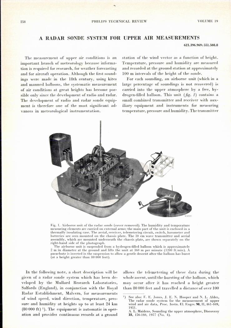
large percentage of soundings is not recovered) iscarried into the upper atmosphere by a free, hy-drogen-filled balloon. This unit (jig. 1) contains asmall combined transmitter and receiver with aux-iliary equipment and instruments for measuringtemperature, pressure and humidity. The transmitter
Fig. 1. Airborne unit of the radar sonde (cover removed). The humidity and ternperat.uremeasuring elements are carried on external arms; the main part of the unit is enclosed in athermally insulating case. The aerial, receiver, telemetering circuit, switch, barometer andbatteries are seen mounted on the chassis plate. The 10 cm wave transmitter and aerialassembly, which are mounted underneath the chassis plate, are shown separatelyon theright-hand side of the photograph.
The airborne unit is suspended from a hydrogen-filled balloon which is approximately2 m in diameter at the ground and lifts the unit at 360 m per minute (1200 ft/min). Aparachute is inserted in the suspension to allow a gentle descent after the balloon has burst(at a height greater tban 80000 feet).
In the following note, a short descript.ion will begiven of a radar sonde system which has been de-veloped by the Mullard Research Laboratories,Salfords (England), in conjunction with the RoyalRadar Establishment, Malvern, for measurementsof wind speed, wind direction, temperature, pres-sure and humidity at heights up to at least 24 km(80000 ft) 1). The equipment is automatic in oper-ation and provides continuous records at a ground
allows the telemetering of these data during thewhole ascent, until the bursting of the balloon, whichmay occur after it has reached a height greaterthan 80000 feet and travelled a distance of over 100
1) See also: F. E. Jones, J. E. N. Hocper and N. L. Alder,The radar sonde system for the measurement of upperwind and air data, Proc. Instn. El. Engrs. 98, II, 461-469,1951.A. L. Maidens, Sounding the upper atmosphere, Discovery18, 156-160, 1957 (No. 4).

1957/58, No. 9 RADAR SONDE 259
Fig. 2. Left: the aneroid barometer; right: the fine-wire resist-ance thermometer; centre: the skin hygrometer. The aneroidand hygrometer are conventional elements, but the thermometeris a considerable improvement over earlier types. It is con-structed with fine, coiled-coil, tungsten wire, has a very shorttime constant and a very small radiation error at highaltitude.
miles from the release point. Tracking the flight ofthe balloon by radar at the ground station providesthe data necessary for determining the wind vectorand height at each moment. Conventional radarmethods, which depend on a pulse signal transmittedby the ground station being reflected by the target,would involve a very high transmitting power inorder to enable the balloon to be tracked during itswhole flight. Therefore in this radar sonde a systemknown as "secondary radar" has been employed.The airborne transmitter is made to send a pulse(or in fact 2 pulses, see later) every time the airbornereceiver picks up a pulse signal transmirted by theground station. The time delay measured at theground station between the departure of the
• "interrogating pulse" and the arrival of the "res-ponding pulse" is a direct measure of the range ofthe balloon; the azimuth and elevation angles of thetransmitting aerial, which is automatically keptaligned on. the balloon, convey the information con-cerning its direction.The interrogating signal has a frequency of 152.5
Mcfs and is transmitted at a peak power of 50 kWwith a pulse repetit.ion rate of 404 pulses per second.The responding signalof the airborne transmitterhas a frequency of 2850 Mcfs and is radiated at apeak power of 0.03 kW.
For the sensing of pressure, humidity and temper-ature, the airborne unit carries an aneroid barom-eter, a goldbeater's skin hygrometer and a resist-ance thermometer (fig. 2). The changes in theseelements under varying atmospheric conditions areconverted into voltage variations which, in turn,control an "encoding" circuit. This circuit is trig-gered byeach of the interrogating pulses, derivedfrom the receiver, and generates a pulse of its ownwith a time delay dependent on the control voltage.The airborne transmitter is operated both by this.delayed pulse and by the interrogating pulse and
thus transmits back to the ground a pair of pulsesfor each interrogating pulse, the time delay betweenthe two pulses of a pair representing the reading ofthe meteorological instrument. The control voltagesof the three instruments are brought into eperationin sequence by a motor-driven switch, so that eachinstrument reading is encoded once every 17 seconds.
The airborne centimetric transmitter contains atriode transmitting valve, controlled by a blocking-oscillator modulator and mounted in a coaxialcavity designed to facilitate large-scale production.The transmitter aerial is an unipole with counter-poise (fig. 1). The power supply of the sonde com-prises three primary cells and a vibrator.
The ground equipment is divisible functionallyand physically into two groups. The radar group isconcerned with the interrogation of the airborneunit, reception of the return' signal and determina-tion of the basic positional data (azimuth angle,elevation angle and slant range of the balloon as afunction of time). The computer group continuouslytranslates the positional data into wind speed anddirection, decodes the t.elemetering signal and re-cords all the results in graphical and printed form.
The radar equipment is illustrated infigs 3 and 4.The transmitting aerial (a Yagi array) and the
Fig. 3. Tbe Yagi array transmitting the 50 kW interrogatingpulses of 2 m waves is mounted on a common pedestal withthe receiving aerial, a 5 ft diameter parabolic reflector withnutating dipole. They are automatically kept aligned on theballoon.

260 PHILlPS TECHNICAL REVIEW VOLUME 19
recervmg aerial (a parabolic reflector) are mountedon a common pedestal driven by a motor servo-system. The receiving aerial is fitted with a nutatingdipole which produces a conical scan of the narrowaerial beam and superimposes a modulation on thereceived signal when the aerial is incorrectly aligned.This error signal steers the servosystem so as togive accurate automatic following of the balloonin direerion. The microwave receiver, which isequipped with automatic gain and frequency con-trol, amplifies the signal from the balloon anddelivers it to the automatic ranging system and thetelemetering system. The ranging system is of anovel type in which the rotation of a motor-driven,
of a mile to be measured; full tenths of a mile aredetermined by counting the number of oscillationsof a crystal calibrator occurring between transmittedand responding pulse. The calibrator controls thepulse repetition frequency of the transmitter andoscillates with a time period exactly correspondingto one tenth of a nautical mile in radar range. Thereceived signal is monitored and readings of rangeR, azimuth e and elevation E are provided by adisplay unit (fig. 4). This unit is also fitted withthe manual controls for range and aerial positionwhich are used at the beginning of a flight beforethe equipment is finally switched over to fullyautomatic operation.
Fig. 4. The radar console. The left-hand unit contains the SOkW transmitter, the right-hand unit the 10 cm wave receiver and the automatic ranging and aerial-alignmentequipment. The centre unit is the display and control system.
phase-shifting transformer is related to the changein distance of the balloon, so that the speed ofrotation is an accurate measure of the radialvelocity of the balloon (radial wind component). Arotation of 3600 is equivalent to a change in distanceof one tenth of a nautical mile. The phase-shiftingtransformer, therefore, permits fractions of a tenth
The continuous computation of the wind vector(which is parallel to the surface of the earth) iseffected from the tangential and radial wind com-ponents, given by the equations (in spherical polarcoordinates) :
VT = R (dejdt) cos E,VR = (dRjdt) cos E - R(dEjdt) sin E.

1957/58, No. 9 RADAR SONDE 261
Fig. 6. The telemetering console. The left-hand unit contains wind-speed and heightrecorders, the right-hand unit encoders and temperature, pressure and humidity recordersand the centre unit a digital computer and teleprinter.
An important feature of these equations is theoccurrence of the derivatives of (slant) range R,azimuth e and elevation E with respect to timet, i.e. the radial and angular velocities. The auto-ranging and auto-alignment circuits are so designedas to provide signals directly proportional to thesevelocities. The wind computer which determinesthe vector resultant of VT and VR is illustratedinfig. 5. It is an analogue computer employing pre-cision potentiometers for multiplication and mag-slips (synchros) for trigonometrical computation.The vector amplitude and direction are derivedfrom VT and VR in a "triangle-solver" magslipwhose rotor shaft assumes a position correspondingat every moment to the wind direction. A 4 ftdiameter recording table is directly coupled to thisshaft and a recording pen is driven at a constantspeed in a radial direction across the table. The penthus traces out a continuous graph of instantaneouswind direction against time. A voltage proportionalto the vector amplitude, i.e. the wind speed, isinduced in the magslip rotor coil and is recordedby a conventional recording meter. The height ofthe balloon, corrected for earth curvature, is com-puted by similar analogue methods and recordedas a function of time.The ground telemetering cquipment, shown in
fig. 6, is designed to identify the coded signals fromthe balloon, to measure accurately the time delaybetween the ranging and telemetering pulses andto encode the results in a form suitable for operatinga standard teleprinter. The time delay is measuredby allowing crystal-controlled timing pulses, with aone microsecond separation, to pass through a gat-
93883
Pig. 5. The wind computer. A mag slip turns the rotatable 4 ftdiameter table so that at every instant it has a position corre-sponding to the computed wind direction. A recording penmoving at constant speed along the fixed radial arm tracesout a graph of wind direction as a function of time (cf. fig. 7).
ing circuit during a period initiated by the rangingpulse and terminated by the telemetering pulse.The total number of timing pulses corresponding tofive hundred pairs of signal pulses is counted by anelectronic counter and the average delay is trans-ferred to the teleprinter encoder. The figures areprinted by the teleprinter in five columns, each offour digits, corresponding to the three meteorologi-cal parameters and two reference signals which arealso transmitted by the airbome unit. Coding sig-

262 PHILIPS TECHNICAL REVIEW VOLUME 19e
TELEPRINTER RECORDPR TR P T u' PR TR T UIS" Ul1 :~l ~JI. lJIJJ-BAUOOH41/2 H!l 'JO' = LAUNCH.,.. 1111 "Hl.,.. ~m mz "'1 Wl-1 :!l: ~~~119
' ".. Hu-IS.,.. '" ...,~ )l1. 1111 im !ift
... ~m :m.,., '" Jl)l
~ 'Si' )21' .,., JU) m' "Ol 1111
~ ~: .... ~:'~ !:~ m ll1l "".". ''''1 "'0 mI In.IHI )lI. m; ''0) Ill'
..,. ):lJ ".. IJl'..~ JUl "U 191' Hl ..'119 )lIJ ..., 'lU ,,,)0 '" H'5 ,,,, nu.~, )lIJ IlJ' '5H HI''''_';''2 ·"SO )Ill ml u,: 11":m )111 US' 1515 Ulo' ::~: 1''' mi IUO m~-16.,,, )ll. 1211 "5' n~, '" 211>'
Hit "Ol .,.r. "~' '''So) '" .~:. UH nu.,., )11. 1)1. "ll g:!'590, )lIJ 1))) IUS .." )IU ... laU UI'.~,. )lil UH ",1 11)5 '''51 )ll' :g:~ nu n1J.", ~m nu .", :m
..,. UH IJ ..' 1nl.,,, ,,,, .". ..." :m ~m :m..." )119.,,, ~m U,) ::~; ... )1 )lIJ "'. Hn
"" un ",) "5n JU' "" 1101 nU_17.," nu m~ ui' 1,15,-3JU' .,u
.m Jl11 ::1~ ~m :t~ IJ)9 1)11
:~ .., U" m~ :m nOl 1110
"'1 UH)l1. 'SlO .,.. i:t: 1050 JlIl IU, nu nn:= JlH '51' .,.. .. 6 .. ,
~U, :m "lO HU)l,. '5"J ut' 2)'0 ..,.., "! IlO)Jln "., "·'5 l1U "U9 ,)U .n, ,...
"" )U, i~ .)0) U95 "~.9 "1" 2611 '1'"..., 12'"
.)U
~m_4 :t;~ ~m "0) U)9 1115.... ", U95 ... :)20 , n'9 tm_IS<&0, JlU ~~!:m U5' ..,. ~2U :H~ "" nu.... Jl2) in! ..,., ... "" :m.... r" ..,.., )IU 'JI>I mi:!ll ~::m :m U'S .." lm 'JU '111
UI' .." ·na m~.." )UI 11)1 ..., 11n ....~ 5 ::'6" Jm 115) :m m~ = ....
''') ", 1111 ......u, )U, "" "" ...,"'5 )11, .." 'Ju un_5
.... '55'.,,,
-19.... ~m :m ')1' 'u, .... )1)5 ...,. nu nu"'5 .". llU ..,., nn :;H U1l
'''5 ,... m~ .,,, Ji~.... jlZl "'1 HU"'1> ,... ..,.') .... '" ...,
.6,. nn "".,,, UJ: .... )1)0 '525 "" IJ65",. ua .,,, ~m ..., llll ." . .,.. m::::: ,." m; ..I.., un .5.5 nu)U, ".. :m ..,., :u: ....•,u )ZII ~ m: ~:! U)Z UlO
"'" )ll' "" "".,.. "" :~'1;-20.... )ll. rul .". lI'l,o-6 ..., J')D '59' U)l.... )lil .", IIJ5 ..I.., '" :!ll "U :m:m m: ..., ~H g!i
.... ,no lUl..., ..I..., )IJl .615 1635 :m.'" )ll, m! ,,,. )llD ..., n~~mI )lll "" .... :::: )l)0 :m :m)ln m! .," mi mz J~!:m )111 .U' ,I.., :~n n",)111 .... :::: )l)0 m: IJ")
"11 Jll' ..., "19 "5'_7 )In .611 116J_21.U6 )11' m! "UI "55 .... JU' .... "" n.5.... ~'l' "'5 "'5
.... m .,,, n)l lh.).616
)~~ J~~~ .", ,,,. .,.., nu "U .", HU•'u "'59 1911 .," HU m. nu"., n" "" "'55 "".,,, m~ ....
"., )11' IJl. .'5J '" . ..I..., m~ 'U)•6zt ~w "41 .'J' "'l :::: )lIJ (1)5 Il".611 ", 1)61 .." ",. )l)0 '1') 165l I1U'UO )119 m~ "H .." :%!! nu •1.., esn .....t)l )U, '091 .,,, )IU 'ln "n IJ"_22,,)1 )It, e-n .on 190,-8 :::1 Ju4 '161 lllJ 11107:m )U, Z')l :gn ...' )11' .,U etu BU)ll~ 2.J5 :m ..,., ~w. ·lIO 211)..,. )121 Z'9~ !g:~ ...., HU IJl) 11.5.6)2 ~m 2515 lUI ......, ,m .ns nil m.l")' 2528 :m ~m .6., )U, ·S~l Z11~ .,,,.iJ' )lU "" .", )U' :m lUI mI'U' m~ '>0, U5. :i!i JU' lua"J' ng 'OIJ IU5 ~m d" ll~' 1161"n )Ill, ''J'5 ::~:-9 ,,,'l! d)) .... lJ~23
"" )1)) lion '0" :::; mz d" 111) 11.''6n )21. 26)1 4011 ~:~ .,., "" 1) ..6
:tn )2)1 :65) .,,, • 64' mz :m .... IJ,",)U) 1611 ~., :m "oH IJ). 11".,,, JU, ,.,a '015 ....., JU!.' ~H lJlJ ,nI
"J6 JUS ~m 'Oll HU ,~" )IIS IJ)) I1,L..." )128 ~., ... sa )lil 1115 '1610:m JU, nl.· ~ .6., JUJ .sn "" m~)114 im ..,. !:~~JUl :;.3~ m~..,. JUl J9" "'1_10 Jl1~ 1)~6_24...; )I,ol ..dl) ~!~'Ut .." )UI .~Il .... lhl..., )l)0 la.) 111' ''''' )ll'! .,,, i'i~ ,hIJ."6 )ua lal.' IJ)I.Ion Jl)1 11115 "') m~ .OSI JU,! :m Hp
"5J Ui'" "5:1 IJ":t:~ )11' zen '<JH .'5J )IZI .9)1 "~1 lh5)IH 191J "11 nil.... )l15 l'JU m; Ill) 0651.1 )119 ."1 ..... lJ~'
:!!1 )ll) 1')5) :m '~5' )ll' .,., I"') nu)lIl 19n Hf>1 .'51 )1)1 "" z,n 1J~'
';') JUh .", ".) 11~_lr'~~l w' :;l~ "" 116).~~. JU' lhl:" 11:'_25.... lUl JOIJ ,,,. .." "~II U)1 '911 l"lj. 111>6:m )IU )0)) ,al~ a~ .~~.)111 .", '"'' 11'"
)11' )0'" )JU ...~~JIJ' ·,n .u. ",J
E:: JUJ 'Ol' H:Z nu ...,. )2)1 .".. 2"~J 116.)Ut )05' 'b~" )lJ~ '9~oQ m' 1161)1)0 )1115 "., 1)01 '''5~ )IJO .,,, 1161::; JU, JI1) )JU II>~' '''51 llJU ,... il~: 1}6.Jl)1 )IH )15· IJOI ...~:. )IJO '0" IJ,;5
".) JUl )1'0 nu II>~, .6~!I )1)C ,... ~m 1165JU, JIJ) )1U I~" '~5' JIJO "., 116.
,... ~m '"l nil a:-12 .. -26~" '''' ) ..,. ."57 )1)1 501C ~m g~t::~ )UJ )U) )10" lffi :m )1)1 ,."..., )UJ )I.' "'.. )1)) ~z nIl :mm~ )1.1 )u:. :~î; )2)) ...,'i" )l16 )ion m~ •IIJ. ".. l&,~ IJ~''''5 )Ui, )l" ".. ~ )IJ' ,... ~~1 116:'~., JlU HIJ ,,)1 g:; m~ "., ;zn.~o, )lz, )J~3 n5) )1)1 ,.,.'~·5 )lIl ))1>1 )5J) 1Jl'-'3 1165 -27
~m i2ll »81 ,,,. lJll '662 )1)' m. 26U 116'
'" J';!' JU' m: :W )In l::1 11>5' 116'm. '''I )'~5 nJ' 2670 :mBALLOOHJUl )u, "). IJlI '''5' )l)' Wl ""JUl )"" )lIJ "29 ." .. mt ~ mKi BURST
:::l JUl ,.... "" Ill' illi )IJ.)U, "" ))8) 'H).u, )IU ,.", )J.' n" ~m "" ~~!Z 1l)1.~., )lU '5" )Ju If" ,.,. 115).,., JU' )561> "" "'5 .... )1)) ".. 1651 1155...., )Ul ~~~~m "01-14 :W ~m ~m ".. m:-2S.6., JUl n:: nu..., )tI) JU. :m )I)) '0)' ",. 115....., )U3 '''1 )1)' HS1 )2), ,... 21)' ll5J:t:; )Il) ,... )101 115) ·"57 )lJ) ,.n lU')l21 ,... m~ IJ" "59 JUl ,... .... m~:!:: )lIJ )J1l H5. ..,. )IJ) ".. '1:')lld UH )Ut lhl "51 )2)) ,." hn Ut.6., )l10 HSO JU" nu '''59 JIJ) = ;Z"..,. )llJ )JJb JO" 11·'_15 '''5' )1)
PR,TR- REFERENCES FIGURES REPRESENT PULSEP- PRESSURE TIME DELAY IN TENTHS OFT - TEMPERATURE A MICROSECONDU- HUMIDITY
Q390S
Fig. 7 Fig. 8
Fig. 7. A typical wind direction record obtained from the radar sonde system.
Fig. 8. Typical teleprinter record obtained from the radar sonde system.
nals interposed in the airhome unit switching se-quence are used to ensure that the results are print-ed in the correct columns.
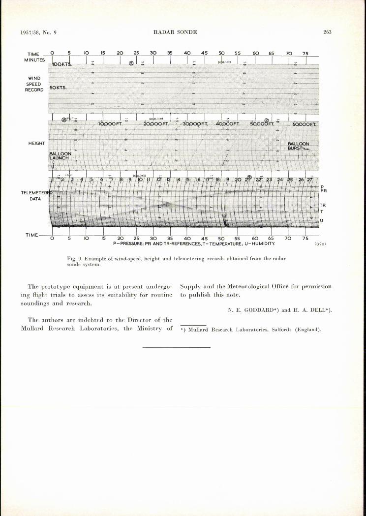
Some typical flight records, which are self-explan-atory, are shown in figures 7,8 and 9. The equip-
ment is designed to measure wind speed with anerror not exceeding 5 km/hr. The telemeteringchannels are designed for an error of the order0.1%, but at present the meteorological instrumentsthemselves contribute somewhat larger errors.
1957/58, No. 9 RADAR SONDE
TIME 0 5 10 15
MINUTES ,!100KTt ~J_;:; _. I30
I20I
35
I40
I45
I55 60 65 70 75
L <; ~1~,__1 ____,____,I=;'--. .."._I----,---.....,.~-._----------------WIND
SPEED ~r-------~.---------~~~~----~--~__-~RECORD :sG-K.:r-s.~. -__,~- . '----'------. ----~ ..-~~
·~-~~_~x ------_----~---------~~-----~----- __---~----- ..
.. TR'T•• ~.U
93907
Fig. 9. Example of wind-speed, height and telemetering records obtained from the radarsonde system.
The prototype equipment is at present undergo-ing flight trials to assess its suitability for routinesoundings and research.
Supply and the Meteorological Office for permissionto publish this note.
N. E. GODDARD*) and H. A. DELL').
The authors are indebted to the Director of theMullard Research Laboratories, thc Ministry of *) Mullard Research Laboratories, Salfords (England).
263
Related Documents