DKS 504 Vario Instruction Manual DKS 504 VARIO JIG SAW DKS 504 Vario

Welcome message from author
This document is posted to help you gain knowledge. Please leave a comment to let me know what you think about it! Share it to your friends and learn new things together.
Transcript

DKS 504 Vario
Instruction Manual
DKS 504 VARIO
JIG SAW
DKS 504 Vario

2 DKS 504 Vario | Version 1.03
Imprint
Product identification
JIG SAW Item Number
DKS 504 Vario 5902504
Manufacturer
Stürmer Maschinen GmbH
Dr.-Robert-Pfleger-Str. 26
D-96103 Hallstadt
Fax: 0049 (0) 951 96555 - 55
E-Mail: [email protected]
Internet: www.holzstar.de
Information about the operating instructions
Original operating instructions
Published: 09.12.2019
Version: 1.03
Language: English
Author: FL
Copyright information
Copyright © 2019 Stürmer Maschinen GmbH, Hallstadt,
Germany.
Stürmer Maschinen GmbH is the sole owner of the con-
tent of these operating instructions.
Forwarding and reproduction of this document as well as
use and notification of its content is not permitted without
explicit consent. Infringements will lead to claims for da-
mages.
Subject to technical changes and errors.
Contents
1 Introduction ............................................. 31.1 Copyright ............................................................ 31.2 Customer service................................................ 31.3 Disclaimer........................................................... 3
2 Safety ....................................................... 32.1 Legend of symbols.............................................. 32.2 Operator responsibility........................................ 42.3 Operating staff qualification ................................ 42.4 Personal protective equipment ........................... 52.5 Safety labels on the Jig Saw............................... 52.6 General safety aspects ....................................... 5
3 Intended Use............................................ 7
4 Technical Data......................................... 74.1 Table................................................................... 74.2 Type plate........................................................... 8
5 Transport, packaging, storage............... 85.1 Transport ............................................................ 85.2 Packaging........................................................... 85.3 Storage ............................................................... 8
6 Description of the machine .................... 86.1 Illustration ........................................................... 86.2 Scope of supply .................................................. 86.3 Strokes and saw blade selection ........................ 96.4 Optional accessories .......................................... 9
7 Installation ............................................... 97.1 Requirements for the place of installation........... 97.2 Setting up the JIG SAW...................................... 97.3 Selection of the correct saw blade.................... 107.4 Inserting Pinless Blades ................................... 107.5 Clamp the saw blade ........................................ 117.6 Tilt the saw table............................................... 117.7 Mount the saw blade guard and workpiece holder..... 117.8 Align saw blade and saw table ......................... 127.9 Setting the scale ............................................... 137.10 Electrical connection....................................... 13
8 Operation of the Jig Saw ..................... 138.1 Workflow........................................................... 148.2 Carry out internal cuts....................................... 158.3 Cutting serveral workpieces.............................. 158.4 Connecting a separate tool............................... 158.5 Change the tools............................................... 168.6 Working with the hand tool ............................... 16
9 Care, maintenance and overhaul/repair... 169.1 Care after working ............................................ 179.2 Maintenance and repair .................................... 17
10 Troubleshooting.................................. 18
11 Disposal, recycling of used devices . 1811.1 Decommissioning ........................................... 1811.2 Disposal of electrical devices.......................... 1811.3 Disposal of lubricants...................................... 1911.4 Disposal via municipal collection points.......... 19
12 Spare parts .......................................... 1912.1 Ordering spare parts....................................... 1912.2 Spare parts drawing DKS 504 Vario............... 20
13 Electrical Wiring Diagram................... 21
14 EC-Declaration of Conformity............ 22

Introduction
DKS 504 Vario | Version 1.03 3
1 Introduction
You have made an excellent choice in purchasing a
HOLZSTAR Jig Saw.
Carefully read the operating instructions prior to
commissioning.
They describe correct commissioning, intended use and
safe as well as efficient operation and maintenance of
the Jig Saw.
The operating instructions form part of the Jig Saw. Al-
ways keep them at the Jig Saw´s location of use. Please
also observe the local accident prevention regu-lations
and general safety regulations for the use of the Jig Saw.
1.1 Copyright
The contents of these operating instructions are pro-
tected by copyright. Their use is permitted within the con-
text of using the Jig Saw. Any further use shall not be
permitted without written consent by the manufacturer.
To protect our products, we register our rights to our
brands, patents and designs where possible in each indi-
vidual case. We take strong action against any violation
of our intellectual property.
1.2 Customer service
Please contact your specialist retailer if you have any
questions regarding your Jig Saw or require any techni-
cal information. Your specialist retailer will be happy to
support you with specialist advice and information.
Germany:
Stürmer Maschinen GmbH
Dr.-Robert-Pfleger-Str. 26
D-96103 Hallstadt
Repair service:
Fax: 0049(0)951 96555-111E-Mail: [email protected]: www.holzstar.de
Spare parts orders:
Fax: 0049(0)951 96555-119 E-Mail: [email protected]
Please submit any information and experiences you
make during application of the machine as these may be
valuable for product improvements.
1.3 Disclaimer
All data in this operation manual has been compiled on
the basis of the state-of-the-art, valid standards and gui-
delines as well as our many years of expertise and expe-
rience.
The manufacturer shall not be liable for damage in the
following cases:
- Failure to comply with the operation manual,
- Unintended use
- Deployment of untrained staff
- Conversions at one's own responsibility
- Technical modifications
- Use of unauthorised spare parts
The actual scope of delivery may deviate from the des-
criptions and illustrations in this document as a result of
special variants, optional extras or recent, technical mo-
difications. The obligations defined in the supply contract
shall apply in addition to the general terms and conditi-
ons and the manufacturer's general terms and conditions
as well as the statutory regulations valid at the time of
the conclusion of the contract.
2 Safety
This section provides an overview of all important safety
packages for personal protection as well as safe and re-
liable operation. The individual sections contain additio-
nal, task-specific safety information.
2.1 Legend of symbols
Safety instructions
Safety instructions in this operation manual have been
highlighted with symbols. Safety instructions are indica-
ted by signal terms that express the degree of risk invol-
ved.
DANGER!
This combination of symbol and signal term indica-tes a potentially dangerous situation which may cause death or serious injury if not averted.
WARNING!
This combination of symbol and signal term indica-tes a immediate dangerous situation which may cause death or serious injury if not averted.

4 DKS 504 Vario | Version 1.03
Safety
Tips and recommendations
Observe the safety information in these operating in-
structions to minimise the risk of personal injury as well
as material damage and prevent hazardous situations.
2.2 Operator responsibility
Operators are defined as the persons who operate the
machine for commercial or profit-based purposes or pro-
vide the machine to third parties for use or application
and bear the legal product responsibility in terms of the
protection of users, staff or third parties during opera-
tion.
Obligations of the operator:
If the machine is used for commercial purposes, opera-
tors are subject to the legal stipulations in terms of occu-
pational safety. For this reason, the safety instructions in
these operating instructions as well as the safety, acci-
dent prevention and environmental protection regulati-
ons valid at the installation location must be complied
with. In this process, the following shall apply in particu-
lar:
- Operators shall obtain information about valid oc-
cupational safety regulations and determine addi-
tional hazards as part of a risk assessment which
result from the specific operating conditions at the
machine's installation location. Said risk as-
sessment shall be reflected in operating instructi-
ons for machine operation.
- During the entire machine operating time operators
must check whether the operating instructions they
created meet current standards and adapt the ope-
rating instructions where necessary.
- Operators shall clearly manage and specify the re-
sponsibilities for installation, operation, trouble-
shooting, maintenance and cleaning.
- Operators must make sure that all persons hand-
ling the machine have read and understood these
operating instructions. Operators must also regu-
larly train staff and notify of the hazards.
- Operators shall provide staff with the required pro-
tective equipment and wearing the required protec-
tive equipment shall be mandatory.
Operators shall also be responsible for maintaining the
machine in a technically perfect condition. For this rea-
son, the following shall apply:
- Operators shall make sure that the maintenance in-
tervals described in these operating instructions
are complied with.
- Operators shall regularly check that the safety
equipment is fully functional and complete.
2.3 Operating staff qualification
The different tasks described in these operating instructi-
ons require different levels of skills in terms of the qualifi-
cations of operating staff working with the machine.
Exclusively persons of whom it can be expected that
they reliably complete assigned tasks shall be authori-
sed to carry out any tasks. Persons whose reactions
have been impaired shall not be authorized, e.g. drug
users, users under the influence of alcohol or medica-
tion.
These operating instructions specify the following perso-
nal qualifications for the different tasks:
ATTENTION!
This combination of symbol and signal term indica-tes a potentially hazardous situation which may cause minor or light injuries if it is not averted.
IMPORTANT!
This combination of symbol and signal term indica-tes a potentially dangerous situation which may cause material damage or harm the environment if it is not averted.
NOTE!
This combination of symbol and signal term indic tes a potentially dangerous situation which may cause material damage or harm the environment if it is not averted.
Tips and recommendations
This symbol highlights useful tips and recommendati-ons as well as information for efficient and reliable operation.
WARNING!
Risk from inadequately qualified persons!
Inadequately qualified persons are unable to assess the risks when handling the machine, thus putting themselves and others at risk of severe injuries.
- All work must be carried out by qualified persons
only.
- Keep inadequately qualified persons and children
away from the work area.

Safety
DKS 504 Vario | Version 1.03 5
Operating staff:
Operating staff has undergone an induction by the ope-
rator about the entrusted tasks and potential hazards re-
sulting from improper behaviour. Tasks which go beyond
normal operation may only be carried out by the operator
if they are listed in the operation manual and the opera-
tor has made him/herself familiar with them.
Qualified electrician:
Due to the electrician's specialised training, know-how,
experience and knowledge of pertinent standards and
regulations the electrician is in a position to work on the
electrical systems, and autonomously identify and avoid
potential hazards.
Specialist staff:
As a result of specialist training, expertise, experience
and skills in terms of the relevant standards and regulati-
ons, specialist staff is able to complete the tasks they are
entrusted with and independently identify hazards and
avert risks.
Manufacturer:
Certain work must be carried out by manufacturer spe-
cialist staff only. Other staff is not permitted to carry out
this work. Contact our customer service to have the work
carried out.
2.4 Personal protective equipment
Personal protective equipment is intended to protect the
health and safety of persons at work. Staff must wear the
personal protective equipment indicated in individual
sections of these operating instructions when carrying
out the different tasks on the machine.
The personal protective equipment is described in the
following section:
2.5 Safety labels on the Jig Saw
The following safety labels and instructions are attached
to the Jig Saw s (Fig. 1) and must be observed.
Fig. 1: Safety labels
If safety labels on the machine are damaged or missing,
this can cause errors, personal injury and material da-
mage. The safety symbols attached to the machine must
not be removed. Damaged safety symbols must be re-
placed immediately.
As soon as the signs are not clearly visible and compre-
hensible at first glance, the machine must be stopped
until new signs have been attached.
2.6 General safety aspects
Note the following:
- Keep the work area clean and well lit.
- Do not use power tools in potentially explosive at-
mospheres, such as near flammable liquids, gases
or dust. Power tools generate sparks that can
ignite dust or fumes.
- Keep children and unauthorized personnel away
from the power tool. Distractions can cause you to
lose control.
Ear and head protection
The ear protection protects against hearing damage caused by noise. The industrial helmet protects the head against falling objects and bumping against fixed objects.
Eye protection
Protective glasses protect the eyes against projected parts and splashes of liquid.
Protective gloves
Protective gloves protect the hands from compo-nents with sharp objects as well as friction, abrasion, and deep-cut injuries.
Respiratory Protection
The respiratory protection is used to protect the respi-ratory tract and the lungs before the intake of dust particles.
Safety boots
The safety boots protect the feet against crushes, fal-
ling parts and slipping over on slippery under-ground.
Protective clothing
Protective work clothing means tight-fitting clothing
with low tear resistance.

6 DKS 504 Vario | Version 1.03
Safety
- Do not expose the power tool to rain or moisture.
The penetration of water into a power tool increa-
ses the risk of electric shock.
- Never change the power plug in any way. Do not
use adapter plugs with grounded power tools.
- When operating a power tool outdoors, use an ex-
tension cord that is suitable for outdoor use. The
use of a cable suitable for outdoor use reduces the
risk of electric shock.
- Never use the cable to carry or pull the power tool.
Keep the cable away from heat, oil, sharp edges or
moving parts. Damaged or entangled cables in-
crease the risk of electric shock.
- Do not use a power tool when you are tired or un-
der the influence of drugs, alcohol or medication. A
moment of carelessness when operating power
tools can cause injury.
- Keep the right balance and the right balance at all
times. This allows better control of the power tool in
unexpected situations.
- Do not wear loose clothing or jewelry. Keep hair,
clothing and gloves away from moving parts.
Loose clothing, jewelry or long hair can get caught
in moving parts.
- Use safety equipment. Always wear eye protection.
Safety equipment such as dust mask, non-slip
safety shoes, hard hat or hearing protector, which
are used for suitable conditions.
- Wear safety goggles to protect against flying wood
chips and sawdust. In many cases, a full shield
provides even better protection.
- Wear a dust mask to protect your lungs from toxic
sawdust.
- Certain types of wood and wood products produce
harmful dust emissions when processed. Only use
your machine in a well-ventilated area and use a
suction device.
- Avoid accidentally starting the device. Make sure
that the switch is in the off position before connec-
ting the device.
- The scroll saw must be firmly bolted to a work-
bench. If the saw moves during certain operations,
secure the workbench to the floor.
- This scroll saw is intended for indoor use only.
- Do not cut pieces of material that are too small to
be held by hand.
- Before switching on the saw, empty the worktable
of all objects except the workpiece (tools, waste,
rulers, etc.).
- Remove all adjustment keys before turning on the
power tool. A wrench or key attached to a rotating
part of the power tool may cause injury.
- Make sure that the teeth of the blades point down
to the table and that the blade tension is adjusted
correctly.
- Do not cut the workpiece too fast. Only feed as fast
as the blade cuts.
- Keep your fingers away from the blade. Use a push
stick as you approach the end of the cut.
- Be careful when cutting a workpiece that is irregu-
lar in cross section. For example, molded parts
must lie flat on the table and must not be "defor-
med" when cutting.
- Turn off the saw and make sure that the saw blade
has come to a complete stop before removing saw-
dust or debris from the table or moving away from
the work area.
- Remove the workpiece to be machined only after
the saw blade has come to a complete standstill.
- Make sure there are no nails or foreign objects in
the part to be sawn.
- To avoid injury and damage to the unit, do not cut
multiple workpieces at once.
- Be especially careful with very large, small or irre-
gularly shaped workpieces.
- Disconnect the power plug from the mains before
any adjustments or maintenance.
- DO NOT operate the machine with the saw blade
guard removed.
- Be sure to use the correct blade size and type for
the material.
- Use ONLY approved replacement saw blades.
Contact your HOLZSTAR dealer. Using inferior
blades can increase the risk of injury.
- Only have your power tool repaired by qualified
service personnel, using only identical replace-
ment parts. This ensures that the safety of the po-
wer tool is maintained.
- When connecting the accessory, make sure that
you disconnect it from the saw after use. If the ac-
cessories are not disconnected, there is a risk of
misplacement by turning the tool.

Intended Use
DKS 504 Vario | Version 1.03 7
3 Intended Use
The JIG SAW DKS 504 Vario is used to saw edged wood
or wood-like workpieces, plastics and non-ferrous me-
tals. The scroll saw cuts softwood, plastic and non-fer-
rous metals. In addition, the machine can be easily used
for separating Plexiglas, fiberglass, foam, rubber, leather
and cork. Round materials may only be cut with suitable
holding devices. Only saw blades suitable for the ma-
chine may be used. The use of cutting discs of all kinds
is prohibited. It is suitable for private use, not for indu-
strial use. Proper use also includes compliance with all
information in this manual. Any use beyond the intended
use or otherwise is considered misuse.
For structural and technical changes to the JIG SAW, the
company Stürmer Maschinen GmbH assumes no liabi-
lity.
Claims of any kind due to damage due to improper use
are excluded.
4 Technical Data
4.1 Table
Duty cycle:
The duty cycle S2 30 min (short-time operation) states
that the engine may be permanently loaded for 30 minu-
tes. Otherwise he would heat up unacceptably. During
the break, the engine cools down again to its starting
temperature.
Noise and vibration:
The effect of noise can cause hearing loss.
Minimize noise and vibration!
- Use only flawless devices.
- Clean and service the device regularly.
- Adapt the method of operation to the device.
- Do not overload the device.
- If necessary, have the device checked.
- Turn off the power when not in use.
DANGER!
Certain types of wood and wood products produce harmful dust emissions when processed. Therefore, use your machine only in a well-ventilated room and use a suction device.
WARNING!
Danger in case of misuse!
Misuse of the JIG SAW can lead to dangerous situations.
- Only operate the scroll saw in the power range spe-
cified in the technical data.
- Never bypass or override the safety devices.
- Never work on other materials than specified in the
intended use.
- Only operate the scroll saw in a technically perfect
condition.
- Never work on several workpieces at the same time.
Model DKS 504 Vario
Length 630 mm
Width / Depth 320 mm
Height 380 mm
Weight 12 kg
Supply voltage 230 V
Table length 414 mm
Table width 254 mm
Extraction duct 31 / 35 mm
Saw blade length 133 mm
Stroke speed 550-1600 min‾¹
Max. cutting height at 90° 52 mm
Max. cutting height at +45° 20 mm
Power output 42 W
Power consumption 0,09 kW
Nominal mode drive motor S2 30 minutes
Rotational speed 1650-4800 rpm
Chuck Ø 3,1 mm
Wear ear protection!

8 DKS 504 Vario | Version 1.03
Transport, packaging, storage
4.2 Type plate
Fig. 2: Type plate DKS 504 Vario
5 Transport, packaging, storage
5.1 Transport
Check the Jig Saw for visible transport damage upon de-
livery. In case of visible damage to the Jig Saw, immedi-
ately notify the carrier or your retailer.
5.2 Packaging
All used packaging materials and packaging aids of the
Jig Saw are recyclable and generally need to be trans-
ported to the material recycling.
Crush the packaging material made of cardboard and
supply it to the waste paper collection.
The films are made of polyethylene (PE) and the uphol-
stery parts are made of polystyrene (PS). These materi-
als have to be delivered to a recycling station of the re-
sponsible dumping company.
5.3 Storage
The Jig Saw must be stored thoroughly cleaned in a dry,
clean and frost-free environment. Cover the machine
with a protective tarpaulin.
6 Description of the machine
6.1 Illustration
The illustrations in these operating instructions
serve the general comprehension and may deviate
from the actual type.
Fig. 3: JIG SAW
1 Adjustable lamp
2 Blade guard
3 Top blade holder
4 Workpiece pressure plate
5 Sawdust blower nozzle
6 Blade
7 Table insert
8 Blade speed regulator
9 On/Off switch
10 Dust extraction outlet
11 Table tilt lock knob
12 Angle adjustment scale
13 Hand tool
14 Saw table
15 Blade tension knob
16 Hose (sawdust blower)
6.2 Scope of supply
- Universal grinder without tools
- Saw blade 133 x 3 x 0.3 mm, T18
- Saw blade 133 x 3 x 0.3 mm, T15
- Instruction Manual

Installation
DKS 504 Vario | Version 1.03 9
6.3 Strokes and saw blade selection
Different types of saw blades can be used with the ma-
chine. The saw blade strength and amount of teeth/inch
(teeth division) depends on the radius to be cut.The nar-
rower the radius to be cut, the narrower the saw blade
must be and the amount of strokes must be also reduced
accordingly.
Reference values:
Teeth/inch
Approx. 10 t.p.i. wood from 6 mm to approx. 50 mm
Approx. 18 ZpZ fine sawing work, wood up to approx. 6
mm
Approx. 25 ZpZ plastic, GRP, non-ferrous metals, plexig-
lass
Selecting rotations:
The harder the material, the smaller the number of stro-
kes.
400–600 strokes/min. For narrow radii and thin material
from 0.25 to 0.3 mm
600–1200 strokes/min. For wood and plastic and extre-
mely thin cuts with material strength from 0.25 to 1.3 mm
1200–1600 strokes/min. For cutting hard and soft wood
from 0.5 to 5.0 mm in thickness. Also for plastic,paper,
aluminium, styrofoam, rubber, leather, cork.
6.4 Optional accessories
We recommend using only high-quality original Holzstar
accessories. Faultless operation and optimal work re-
sults can only be guaranteed with original accessories.
- Pin saw blades 135 x 3,0 x 0,25mm
Item number: 5911628
- Pin saw blades 135 x 6,0 x 0,4mm
Item number: 5911660
- Pin saw blades 135 x 6,0 x 0,4mm
Item number: 5911661
- Tool set 103-part in wooden case
Item number: 5912504
7 Installation
7.1 Requirements for the place of installation
Remove the jig saw from its packaging and remove any
protective film. Do not set up or operate the machine in a
damp or wet environment. The humidity should not ex-
ceed 60% and the measured room temperature should
be between 0 ° C and 40 ° C.
The installation or working room must be dry and well
ventilated.
7.2 Setting up the JIG SAW
The Jig saw is already mostly delivered assembled. Only
a few parts have to be mounted after delivery.
To set up the saw is a workbench made of solid wood. A
noise reducing foam pad is not included with the saw.
Such a base is recommended in order to minimize vibra-
tion and noise pollution.
The tools and hardware needed to mount on a work-
bench were not supplied with the saw.
NOTE!
To reduce noise, a rubber interlayer can be placed
between the machine and the workbench. This effecti-
vely prevents vibration and noise.
CAUTION!
Risk of injury due to a machine that is not stably er-
ected!
Check the stability of the machine after placing it on
stable ground.
ATTENTION!
To ensure sufficient stability of the machine, it should
be screwed to the ground. There are 4 holes at the
bottom of the machine housing for this purpose.
DANGER!
Do not overtighten the screws securing the base
plate. The base plate must not be warped.
Wear protective gloves!
Wear protective clothing!
Wear safety shoes!

10 DKS 504 Vario | Version 1.03
Installation
Use the following equipment:
- 4 Hexagon bolts M8
- 4 Washers Ø 8 mm
- 8 Hex nuts M8
The following steps will make the machine operational:
Step 1: After unpacking, park the machine at the desired
location.
Fig. 4: Mounting on a workbench
A: Base plate of the saw
B: Foam rubber underlay
C: Workbench
D: Flat gasket
E: Washer
F: Hex nut
G: Locknut
H: Hex screw
Step 2: Screw the base plate of the machine over the ho-
les with the work surface. Do not over tighten the
screws so that the rubber mat absorbs any vibra-
tion.
7.3 Selection of the correct saw blade
As a rule, choose narrow blades for complicated curved
cuts and wide blades for straight and large curved cuts.
Circular saw blades wear out and must be replaced re-
gularly to achieve optimum cutting results. Saw blades
generally become dull after 1/2 to 2 hours, depending on
the type of material and the working speed. The best re-
sults are achieved with pieces that are less than 25 mm
thick.
If you are cutting workpieces that are thicker than 25
mm, you must insert the blade into the workpiece very
slowly. Be especially careful not to bend or twist the
blade when cutting.
7.4 Inserting Pinless Blades
The adapter allows you to use saw blades with no loca-
ting pins at both ends.
Step 1: Switch off the machine and disconnect the power
plug from the socket.
Step 2: Adjust the locking screw on the adapter until it
covers approximately half of the hole when vie-
wed from the top.
Fig. 5: Insert saw blade adapter
Step 3: Slightly loosen the other locking screw to push
an adapter onto each end of the blade.
Step 4: Insert the knife and adapters into the machine
(Fig.6). Now set the knife to the correct length.
Fig. 6: Insert pinless blades
Cut right angle with the pinless saw blade
Cut from the side of the saw as soon as your workpiece
has a length of more than 405 mm. With the blade posi-
tioned, the table must always be in the 0 ° position.
Remove both setscrews from each blade adapter and in-
sert them into the opposite holes of the blade adapter
perpendicular to the adjustment pin.
Saw blade
Installation
DKS 504 Vario | Version 1.03 11
7.5 Clamp the saw blade
Turning the saw blade tension handle (Fig.7) counter-
clockwise decreases (loosens) the blade tension.
Turning the saw blade tension handle (Fig.7) clockwise
increases (tightens) the blade tension.
Fig. 7: Clamping the saw blade
7.6 Tilt the saw table
Fig. 8: Tilt the saw table
Step 1: Loosen the clamping screw (Fig.8).
Step 2: Tilt the saw table to the left until the pointer indi-
cates the desired angle on the graduated scale.
The worktable can be tilted from 0 ° to 45 ° to the
left.
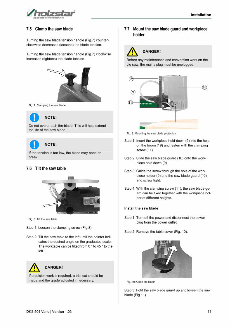
7.7 Mount the saw blade guard and workpiece
holder
Fig. 9: Mounting the saw blade protection
Step 1: Insert the workpiece hold-down (9) into the hole
on the boom (19) and fasten with the clamping
screw (11).
Step 2: Slide the saw blade guard (10) onto the work-
piece hold down (9).
Step 3: Guide the screw through the hole of the work-
piece holder (9) and the saw blade guard (10)
and screw tight.
Step 4: With the clamping screw (11), the saw blade gu-
ard can be fixed together with the workpiece hol-
der at different heights.
Install the saw blade
Step 1: Turn off the power and disconnect the power
plug from the power outlet.
Step 2: Remove the table cover (Fig. 10).
Fig. 10: Open the cover
Step 3: Fold the saw blade guard up and loosen the saw
blade (Fig.11).
NOTE!
Do not overstretch the blade. This will help extend the life of the saw blade.
NOTE!
If the tension is too low, the blade may bend or break.
DANGER!
If precision work is required, a trial cut should be
made and the grade adjusted if necessary.
DANGER!
Before any maintenance and conversion work on the
Jig saw, the mains plug must be unplugged.
19
9
11
10

12 DKS 504 Vario | Version 1.03
Installation
Fig. 11: Loosen the saw blade
Step 4: Press the upper pendulum arm down, then hook
the saw blade to the blade holder.
The blade holder has two notches:
Notch 1: For cutting with the upper saw arm.
Notch 2: To cut at right angles with the Upper saw arm.
Fig. 12: Insert the saw blade
Fig. 13: Insert pinless blade
Step 5: Tighten the saw blade (Fig. 11) and fold down
the saw blade guard.
Change the saw blade
Step 1: Turn off the power and disconnect the power
plug from the power outlet.
Step 2: Remove the table cover (Fig. 10).
Step 3: Fold the saw blade guard up andrelax the saw
blade (Fig.11).
Step 4: Press the upper blade holder down.The saw
blade from the lower blade holderfar away and
upwards.
7.8 Align saw blade and saw table
Step 1: Turn off the power and disconnect the power plug
from the power outlet.
Step 2: Loosen the clamping screw of the workpiece holder
and push the workpiece holder upwards. Then tigh-
ten the clamping screw.
Fig. 14: Position workpiece hold down
Step 3: Release the table lock knob (Fig.15) and tilt the
table until it is approximately at right angles to
the blade.
Step 4: Place a small angle on the saw table next to the
saw blade and lock the table at 90 ° to the angle.
Fig. 15: Tilt the saw table
Step 5: Retighten the table lock using the handle.
DANGER!
If you are using pen-less blades, hook the blade adap-
ter into the front of the blade holder (Fig.13).
DANGER!
Always insert the saw blade so that the teeth point in
the direction of the saw table.
DANGER!
To avoid an accident, switch off the machine before-
hand and disconnect the power plug.

Operation of the Jig Saw
DKS 504 Vario | Version 1.03 13
7.9 Setting the scale
Step 1: Turn off the power and disconnect the power
plug from the power outlet.
Step 2: Loosen the locking screw (Fig.16) that fixes the
scale display. Move the indicator to the 0 °
mark and tighten the screw.
Fig. 16: Setting the scale
Step 3: Lower the workpiece hold down so that it is re-
sting on the workpiece and secure it.
7.10 Electrical connection
When making electrical connections, make sure that the
characteristics (voltage, mains frequency) comply with
the information given on the rating plate. We strongly re-
commend that this device be connected to the mains via
a residual current device (RCD).
Step 1: Check that the JIG SAW is off.
Step 2: Connect the machine to the mains.
8 Operation of the Jig Saw
DANGER!
Remember that the scale is only a guide and is not re-
liable for accuracy. Make cuts with the piece of waste
to make sure the angle settings are correct.
DANGER!
Danger of electrocution!
Contact with live components may cause mortal dan-ger. Switched on electrical components can cause uncontrolled movements and lead to serious injuries.
DANGER!
All work on the electrical installation may only be car-
ried out by a qualified electrician.
DANGER!
Danger of electrocution!
Contact with live components may cause mortal dan-ger. Switched on electrical components can cause uncontrolled movements and lead to serious injuries.
- Disconnect the power before starting any adjust-
ments to the machine.
WARNING!
Risk of injury!
There is a risk of injury to the operator and other per-sons if they do not adhere to the following rules.
- The JIG SAW may only be operated by a trained
person.
- The operator may not work while under the influ-
ence of alcohol, drugs or medication.
- The operator must not work when he is tired or suf-
fering from concentration-impairing illnesses.
- The JIG SAW may only be operated by one person.
ATTENTION!
Risk of crushing!
Incorrect work on the machine can cause injury to the upper limbs.
DANGER!
- Harmful emissions of wood dust when used indoors.
- Danger due to backlash of the workpiece.
- Danger due to ejection of branch parts and work-
piece parts
DANGER!
- Protect the machine against moisture (danger of
short circuit!)
- Do not overload the machine! You work better and
safer in the specified performance range.
- Never use blunt or damaged saw blades. Check that
the appropriate saw blade is used.

14 DKS 504 Vario | Version 1.03
Operation of the Jig Saw
inweise
Notes for sawing
The saw does not cut wood automatically. The user
allows cutting by guiding the wood into the moving saw
blade.
The teeth cut the wood only on the downstroke.
The wood must be slowly guided into the saw blade, as
the teeth of the saw blade are very small.
Every person who wants to work with the saw needs a
certain amount of study time. During this time, some lea-
ves will surely break.
When cutting thicker wood, special care should be taken
not to bend or twist the saw blade. This increases the
service life of the saw blade.
8.1 Workflow
Step 1: Check that the JIG SAW is turned off and the po-
wer plug is unplugged.
Step 2: Check that all covers and safety devices are pro-
perly installed.
Step 3: The workpiece on foreign objects such as e.g.
Check nails or screws and remove if necessary.
Step 4: Select saw blade, clamp and check the moving
parts for ease of movement.
Step 5: Adjust the tilt angle if necessary.
Step 6: Adjust the position of the workpiece hold down,
blower and lighting. The blower is preset to direct
the air to the most effective point on the cut line.
Make sure the pressure plate is set to secure the
workpiece and direct air onto the cutting surface.
Fig. 17: Adjust the sawdust blower
Step 7: Connect exhaust (eg vacuum cleaner) to exhaust
and switch on.
Step 8: Switch on the saw by pressing the green START
button (Fig.18).
Fig. 18: ON / OFF Switch
Step 9: Set the desired speed (number of strokes) on the
speed controller - depending on the material to
be cut.Turn the speed selector clockwise to in-
crease the number of strokes per minute. Turn
the speed selector counterclockwise to de-
crease the number of strokes per minute.
Fig. 19: Speed control
Step 10: Guide the workpiece against the saw blade.
DANGER!
- Before you start cutting, turn on the saw and hear
the sound that the machine produces. If you notice
strong vibrations or unusual noises, immediately
stop the saw and unplug the power cord.
Wear ear protection!
Wear safety glasses!
Wear respiratory protection!
Wear safety shoes!
Wear protective clothing!
DANGER!
The machine is equipped with a safety switch against
reconnection after voltage drop.

Operation of the Jig Saw
DKS 504 Vario | Version 1.03 15
Step 11: After finishing sawing, switch off the device with
the red STOP button, switch off the suction and
disconnect the mains plug.
When pulling out the workpiece, the blade can be mis-
diagnosed on average. This is usually caused by saw-
dust which clogs the kerf. If that happens, do the follo-
wing:
- Set the switch to OFF.
- Wait for the saw to stop and unplug the power cord.
- Remove the blade and the workpiece.
8.2 Carry out internal cuts
A feature of this scroll saw is the ability to make internal
cuts in a panel without damaging the exterior or perime-
ter of the panel.
Step 1: Check that the machine is switched off and the
power plug is unplugged.
Step 2: Remove the saw blade.
Step 3: Drill a hole in the piece to be cut out inside the
workpiece.
Step 4: Place the workpiece with the hole over the ac-
cess hole on the saw table.
Step 5: Guide the saw blade through the hole in the
workpiece, clamp into the holder and adjust the
blade tension.
Step 6: Carry out the cut.
Step 7: After completing the internal cuts, remove the
saw blade from the blade holders and remove
the workpiece from the table.
8.3 Cutting serveral workpieces
The scroll saw can be used to cut several identical sha-
pes. Several workpieces can be stacked on top of each
other and must be secured together prior to cutting.
The stacked parts must be attached to each other so that
they can be handled as a single workpiece on the table.
8.4 Connecting a separate tool
Step 1: Turn off the power and disconnect the power plug
from the power outlet.
Step 2: Remove the cap of the separate tool connector on
the scroll saw.
Fig. 20: Remove the cover
Step 3: Connect the connection of the tool to the connec-
tion of the scroll saw and tighten.
Fig. 21: Connect the worktool
NOTE!
The scroll saw has an attached work light which lights
up automatically as soon as the scroll saw is switched
on.
The light arm can be bent to bring the light in a
suitable position.
DANGER!
Before adjusting the device and before removing or
replacing the saw blade, the device must be switched
off and the mains plug must be disconnected!
DANGER!
To avoid injury, do not cut multiple workpieces that
are lying on top of each other if they are not
connected.
DANGER!
As soon as the tool is connected to the scroll saw and
the scroll saw is switched on, the tool also switches on
automatically. Therefore, make sure to hold the tool
firmly and securely when turning on the scroll saw.

16 DKS 504 Vario | Version 1.03
Care, maintenance and overhaul/re-pair
8.5 Change the tools
Step 1: Loosen the screw in the hole in the handle.
Step 2: Turn the clamping nut until the spindle lock enga-
ges and the shaft does not turn.
Fig. 22: Change the tool
Step 3: Insert the required tool and tighten the collet with
the supplied key.
Step 4: Remove the tool.
8.6 Working with the hand tool
Observe the following notes when working with the
hand tool:
- Once the tool is connected to the scroll saw and
the scroll saw is turned on, the tool also turns on.
Therefore, make sure to hold the tool firmly and se-
curely when turning on the scroll saw.
- Secure the workpiece which you are working on to
avoid slippage.
- Hold the tool firmly in your hand and always at a
safe distance from other persons.
- Keep children away from the scroll saw and hand
tools.
- Always aim the tool away from your body.
- The slow speed is best for polishing, delicate wood
carving or working on fragile model parts.
- A high speed is suitable for operation on hardwo-
ods, metals and glass, eg. As carving, milling, mol-
ding, cutting and drilling.
- Only put the hand tool out of hand as soon as the
tool stops turning.
- Disconnect the separate tool immediately after use
from the scroll saw, otherwise injury to the opera-
tor.
9 Care, maintenance and overhaul/re-
pair
NOTE!
First insert the shaft of the connection cable into the
connection to the Jig saw and then tighten the
connection.
DANGER!
Disconnect the separate tool immediately after use
from the scroll saw, otherwise injury to the operator.
DANGER!
To avoid the risk of injury, make sure that the blade
guard is mounted over the saw blade when using the
hand tool.
DANGER!
Electric shock is life-threatening!
There is a danger of life in case of contact with cur-rent running through components.Electrical compo-nents that are on can cause uncontrolled movements and lead to the most serious injuries.
- Always disconnect the mains plug before you start
cleaning and maintenance works.
- Connections and repairs of the electrical equipment
may only be carried out by specialized electrical
staff.

Care, maintenance and overhaul/re-pair
DKS 504 Vario | Version 1.03 17
9.1 Care after working
Step 1: Disconnect the power plug from the power outlet.
Step 2: Empty and clean the suction device.
Step 3: Clean the machine from chips and sawdust with
compressed air (Attention: wear safety goggles
and a dust mask!) And / or with a brush or a dry
cloth.
Step 4: Periodically clean the unit with a dry cloth and
mild detergent.
Step 5: Spray or oil all unpainted metal surfaces with a
little anti-rust spray.
Step 6: Lubricate the bearings of the pulleys regularly,
but at the latest after about 25-30 operating
hours, with a high-quality engine grease.
Step 7: Check the power cord regularly for damage. If
the cable is damaged, have it replaced by a qua-
lified technician.
9.2 Maintenance and repair
Maintenance and repair work may only be carried out by
qualified personnel.
If the JIG SAW does not work properly, contact a dealer
or our customer service. The contact details can be
found in chapter 1.2 Customer Service.
All protective and safety equipment must be reinstalled
immediately after repair and maintenance work has been
completed.
Extraction device
Check daily the extraction device on the sufficient func-
tion. If the extraction device does not work or is re-
stricted, it must be restored. Only then can the Jig Saw
be put into operation.
Lubrication
Lubricate the bearings with oil after 10 hours of opera-
tion. After every 50 hours of operation or squeaking from
the bearings, oil as follows:
Step 1: Turn off the unit and disconnect it from the power
supply.
Step 2: Turn the saw on its side.
Step 3: Pry off the rubber caps that cover the pivot axes.
Step 4: Spray a small amount of SAE 20 oil around the
shaft end and bearing.
Step 5: Let the oil soak in this condition overnight. The
next day repeat the above procedure for the op-
posite side of the saw.
Carbon brushes
Your saw has externally accessible carbon brushes that
should be checked regularly for wear.
Step 1: Using a flat-head screwdriver, remove the cap of
the upper brush assembly on top of the motor.
Step 2: Carefully pry the brush assembly out with a small
screwdriver.
Step 3: The second carbon brush is accessible through
the access opening on the bottom of the motor.
Remove this in the same way. If one of the brus-
hes is shorter than 6 mm, replace both brushes
in pairs.
Step 4: Make sure the brush cap is properly positioned
(straight). Only tighten the carbon brush cap with
a hand screwdriver. Do not overdo it!
Fig. 23: Change the Carbon brushes
Drive belt
To change the drive belt, proceed as follows:
Use protective gloves!
NOTE!
Never use strong detergents for all cleaning work.
This can lead to damage or destruction of the device.
DANGER!
Do not remove chips with bare hands. You can suffer
a cut injury through chips and tools!DANGER!
Turn off the saw and disconnect it from the power sup-
ply. The carbon brushes may only be replaced by a
qualified electrician!

18 DKS 504 Vario | Version 1.03
Troubleshooting
Step 1: Turn off the unit and disconnect it from the power
supply.
Step 2: Remove the 3 screws that secure the belt cover.
Fig. 24: Remove the belt cover
Step 3: Remove the belt cover.
Step 4: Remove the ankle strap and dispose of it properly.
Step 5: Lay the new belt over the small gear. Then turn the
larger gear by hand and pull the belt onto the big
gear.
Fig. 25: Change the drive belt
Step 6: Replace the cover and screws.
10 Troubleshooting
11 Disposal, recycling of used devices
For environmental benefits it is necessary to ensure that
all components of the machine are only disposed of by
the provided and allowed means.
11.1 Decommissioning
Immediately decommission used machines in order to
avoid later misuse and endangering of the environment
or of persons.
Step 1: Remove all environmentally hazardous fluids
from the old unit.
Step 2: If necessary, dismantle the machine into mana-
geable and usable assemblies and components.
Step 3: Guide the machine components and operating
materials to the appropriate disposal routes.
11.2 Disposal of electrical devices
Electrical devices include numerous recyclable materials
as well as environmentally hazardous components.
These components must be disposed of separately and
professionally. In case of doubt, please contact your mu-
nicipal waste management company.
For the recycling process, please request the assistance
of a specialized waste disposal centre if required.
Drive belt
Fault Possible cause Remedy
Engine does not start No mains voltage,
Connection cable defect.
Engine defective
Have the power supply checked by
qualified personnel.
Let replaced the engine by qualified
personnel.
Saw blades break 1. Too high or too low voltage
2. Worn out saw blade
3. Saw blade twisted
4. Wrong saw blade
1. Pay attention to the correct
voltage.
2. Reduce feed, less feed.
3. Avoid lateral pressure on the saw
blade.
4. Fine saw blades for thin work-
pieces, coarse saw blades for thic-
ker workpieces.
The Saw blades loosed while wor-
king
1. Saw blade is not correctly adjusted 1. Loosen the saw blade retaining
bolt and reorient the bracket.

Spare parts
DKS 504 Vario | Version 1.03 19
11.3 Disposal of lubricants
The manufacturer of the lubricant makes the disposal in-
structions for the used lubricants available. If applicable,
ask for the product-specific data sheets.
11.4 Disposal via municipal collection points
Disposal of used electrical and electronic equipment
(Applicable in the countries of the European Union and
other European countries with a separate collection sys-
tem for these appliances).
The symbol on the product or its packaging indi-
cates that this product should not be treated as normal
household waste, but must be returned to a collection
point for the recycling of electrical and electronic equip-
ment. By helping to properly dispose of this product, you
are protecting the environment and the health of others.
Environment and health are endangered by improper
disposal. Material recycling helps to reduce the con-
sumption of raw materials. For more information about
recycling this product, contact your local community, mu-
nicipal waste management, or the shop where you pur-
chased the product.
12 Spare parts
12.1 Ordering spare parts
The spare parts may be purchased with the authorised
dealer or directly with the manufacturer. Please find the
corresponding contact data in Chapter 1.2 Customer
service.
Indicate the following basic information for spare part or-
ders:
- Type of device
- Serial number
- Position number
- Quantity
- Year of manufacture
- Required mode of dispatch (mail, freight, sea, air,
express)
- Address of dispatch
Spare part orders which do not include the above indi-
cations may not be taken into consideration. If the indica-
tions regarding the mode of dispatch are missing, the
product is dispatched at the discretion of the supplier.
You will find indications regarding the device type, item
number and year of manufacturing on the type plate
which is fixed on the device.
Example
The drive belt for the Jig Saw DKS-504 Vario must be or-
dered. The drive belt has the number 95 in the spare
parts drawing 1.
By ordering spare parts, send a copy of the spare parts
drawing (1) with the marked part (drive belt) and marked
positon number (95) to the dealer or spare parts depart-
ment and provide the following information:
- Type of device: JIG SAW DKS 504-Vario
- Item number: 5902504
- Drawing number: 1
- Position number: 95
DANGER!
Danger of injury by the use of wrong spare parts!
Dangers may result for the user and damages as well as malfunctions may be caused by using wrong or damaged spare parts.
- Only use original spare parts of the manufacturer or
spare parts admitted by the manufacturer.
- Always contact the manufacturer in case of uncer-
tainties.
Tips and recommendations
The manufacturer's warranty will become null and void if non admitted spare parts are being used.

20 DKS 504 Vario | Version 1.03
Spare parts
12.2 Spare parts drawing DKS 504 Vario
The following drawing are intended to help in case of service, to identify necessary spare parts. To order send a copy of
the parts drawing with marked components to your dealer.
Fig. 26: Spare parts drawing JIG SAW DKS 504 Vario

Electrical Wiring Diagram
DKS 504 Vario | Version 1.03 21
13 Electrical Wiring Diagram
Fig. 27: Electrical Wiring Diagram DKS 504 Vario

22 DKS 504 Vario | Version 1.03
EC-Declaration of Conformity
As per machine directive 2006/42/EC, Appendix II 1.A
Manufacturer / distributor: Stürmer Maschinen GmbH
Dr.-Robert-Pfleger-Str. 26
D-96103 Hallstadt
hereby declares that the following product
Product Category: Holzstar® Woodworking machines
Machine type: JIG SAW
Designation of the machine: DKS 504 Vario
Item number: 5902504
Serial number*: ___________________
Year of manufacture*: 20____ * please fill in according to the information on the type plate
corresponds, on the basis of its design and construction, as well as the version that we have put into circulation, with the
relevant fundamental health and safety requirements of (subsequent) EU Directives.
Relevant EU Directives: 2014/30/EU EMC-Directive
2011/65/EU RoHS-Directive
2012/19/EU WEEE-Directive
The following harmonized standards have been applied:
EN 61029-1: 2000 +A11+A12 Safety of transportable motor-operated electric tools - Part 1: General requirements
EN 55014-1:2017 Electromagnetic compatibility - Requirements for household appliances, electric tools and similar apparatus - Part 1: Emission
EN 55014-2:2015 Electromagnetic compatibility - Requirements for household appliances, electric tools and similar apparatus - Part 2: Immunity - Product family standard (CISPR 14-2:2015)
EN 61000-3-2:2014 Electromagnetic compatibility (EMC) - Part 3-2: Limits - Limits for harmonic current emissions (equipment input current <= 16 A per phase) (IEC 61000-3-2:2014)
EN 61000-3-3:2013 Electromagnetic compatibility (EMC) - Part 3-3: Limits - Limitation of voltage changes, voltage fluctuations and flicker in public low-voltage supply systems, for equipment with rated current <= 16 A per phase and not subject to conditional connection
Responsible for documentation: Kilian Stürmer, Stürmer Maschinen GmbH,
Dr.-Robert-Pfleger-Str. 26, D-96103 Hallstadt
Hallstadt, 25.01.2019
______________________Kilian StürmerGeneral Manager
14 EC-Declaration of Conformity

Notes
DKS 504 Vario | Version 1.03 23
15 Notes

www.holzstar.de
Related Documents


![a comuna de paris FINAL.indd 1 24/08/2015 11:40:02 · R io S e n a R io S e n a R io S e n a ... a família real francesa), ... do-o de “o chapéu [napoleônico] sem a cabeça”](https://static.cupdf.com/doc/110x72/5be8534609d3f29e6f8ba644/a-comuna-de-paris-finalindd-1-24082015-114002-r-io-s-e-n-a-r-io-s-e-n-a.jpg)