A QUADCOPTER CONTROLLER TO MAINTAIN RADIO LINK QUALITY A.H.M.Ayyoob (Reg No. 2010CS019,Index no. 10000194) University of Colombo School of Computing A Thesis Submitted In Partial Fullfillment Of The Requirements For The Degree Of B.Sc in Computer Science For Subject Individual Project - SCS 4001 Recommended For Acceptance By The Department Of Computer Science Supervisors Dr.Chamath Keppitiyagama Dr.Kasun de Zoysa JANUARY 19, 2014

Welcome message from author
This document is posted to help you gain knowledge. Please leave a comment to let me know what you think about it! Share it to your friends and learn new things together.
Transcript

A QUADCOPTER CONTROLLER TOMAINTAIN RADIO LINK QUALITY
A.H.M.Ayyoob(Reg No. 2010CS019,Index no. 10000194)
University of Colombo School of Computing
A Thesis SubmittedIn Partial Fullfillment OfThe Requirements For The
Degree Of B.Sc in Computer ScienceFor Subject Individual Project - SCS 4001
Recommended For AcceptanceBy The Department Of Computer Science
SupervisorsDr.Chamath Keppitiyagama
Dr.Kasun de Zoysa
JANUARY 19, 2014

To God for everything I am, and everything I ever will be.To My parents and my family.

Abstract
The excellent maneuverability and the availability of large number of sensors includinggood quality video cameras make quadcopters an attractive device for deployment insurveillance systems. Most video surveillance systems require a real-time high qualityvideo to stream from the cameras on the quadcopter to the base-station. This requiresa good quality radio link between the quadcopter and the base-station. Furthermorea good link quality is also needed to be maintained to make sure that either controlsignal or the result from o�ine processing gets back to the quadcopter without any loss.The link quality depends on the distance of the quadcopter from the base-station; thesignal strength decreases with distance. The link quality also depends on the noiseof the environment. This study consider the problem of hovering a quadcopter atthe maximum distance from the base-station while maintaining a link quality at agiven value indicated by the Signal to Noise Ratio (SNR). This solves the problemon having an empirical measurement for the distance on a wireless device. Whereinhaving a pre-set value for distance does not fully utilize the maximum range it couldfly or it would break the communication link if the pre-set value for distance is greaterthan the communication range. There are existing solution on the field of roboticsthat incorporates the concept of link aware mobility. However, this is the first time apractical implementation and experiments is considered on the quadcopters. A novelapproach is proposed on link aware mobility - An autonomous controller that uses acognitive based model to learn the SNR change and provide necessary feedback. SNRis a metric that depends on many factors. Therefore a suitable in depth analysis isdone on how to use the SNR as a signal metric.

Contents
Contents i
List of Figures v
List of Tables viii
Acronyms and Abbreviations ix
1 Introduction 1
1.1 Quadcopter . . . . . . . . . . . . . . . . . . . . . . . . . . . . . . . . . 2
1.2 Motivation . . . . . . . . . . . . . . . . . . . . . . . . . . . . . . . . . . 2
1.3 Thesis Contribution . . . . . . . . . . . . . . . . . . . . . . . . . . . . . 3
1.3.1 Aims and Objectives . . . . . . . . . . . . . . . . . . . . . . . . 4
1.3.2 Research Question . . . . . . . . . . . . . . . . . . . . . . . . . 5
1.3.3 Scope and Limitations . . . . . . . . . . . . . . . . . . . . . . . 5
1.4 Organization of Thesis . . . . . . . . . . . . . . . . . . . . . . . . . . . 6
2 Background 7
2.1 Unmanned Aerial Vehicles . . . . . . . . . . . . . . . . . . . . . . . . . 7
2.2 Signal Quality Measurement Metrics . . . . . . . . . . . . . . . . . . . 8
2.2.1 Received Signal Strength Indicator (RSSI) . . . . . . . . . . . . 8
2.2.2 Signal to Noise Ratio (SNR) . . . . . . . . . . . . . . . . . . . . 9

Contents ii
2.2.3 Signal to Interference plus Noise Ratio (SINR) . . . . . . . . . . 9
2.3 Literature Survey . . . . . . . . . . . . . . . . . . . . . . . . . . . . . . 10
2.3.1 Human Controlled Combined with Signal Based Steering Model 10
2.3.2 Autonomous Controlled Combined with Range Based SteeringModel . . . . . . . . . . . . . . . . . . . . . . . . . . . . . . . . 11
2.3.3 Autonomous Controlled Combined with Signal Based SteeringModel . . . . . . . . . . . . . . . . . . . . . . . . . . . . . . . . 13
2.3.4 Summary . . . . . . . . . . . . . . . . . . . . . . . . . . . . . . 18
2.4 Techniques that used on this project . . . . . . . . . . . . . . . . . . . 18
2.4.1 Signal Propagation . . . . . . . . . . . . . . . . . . . . . . . . . 18
2.4.2 AR Drone 2.0 . . . . . . . . . . . . . . . . . . . . . . . . . . . . 19
2.4.3 Navigation model . . . . . . . . . . . . . . . . . . . . . . . . . . 20
2.4.4 PID Controller . . . . . . . . . . . . . . . . . . . . . . . . . . . 21
2.4.5 Kalman Filter . . . . . . . . . . . . . . . . . . . . . . . . . . . . 22
3 Design 24
3.1 System Architecture . . . . . . . . . . . . . . . . . . . . . . . . . . . . 25
3.1.1 Low Level Controller . . . . . . . . . . . . . . . . . . . . . . . . 26
3.1.2 Asynchronous Data Reader and Writer . . . . . . . . . . . . . . 28
3.1.3 State Estimator . . . . . . . . . . . . . . . . . . . . . . . . . . . 28
3.1.4 Position Controller . . . . . . . . . . . . . . . . . . . . . . . . . 33
3.1.4.1 Altitude Hold . . . . . . . . . . . . . . . . . . . . . . . 34
3.1.4.2 Signal Controller . . . . . . . . . . . . . . . . . . . . . 34
3.2 Design Summary . . . . . . . . . . . . . . . . . . . . . . . . . . . . . . 40
4 Implementation 41
4.1 Wi-Fi Network . . . . . . . . . . . . . . . . . . . . . . . . . . . . . . . 42

Contents iii
4.2 SNR Reader . . . . . . . . . . . . . . . . . . . . . . . . . . . . . . . . . 42
4.3 Controller Implementation . . . . . . . . . . . . . . . . . . . . . . . . . 43
4.3.1 Data Reader and Writer . . . . . . . . . . . . . . . . . . . . . . 43
4.3.2 State Estimator . . . . . . . . . . . . . . . . . . . . . . . . . . . 45
4.3.3 PID Controller . . . . . . . . . . . . . . . . . . . . . . . . . . . 48
4.3.4 Altitude Hold . . . . . . . . . . . . . . . . . . . . . . . . . . . . 49
4.3.5 Reconnaissance for SNR vs Distance . . . . . . . . . . . . . . . 50
4.3.6 Signal Controller . . . . . . . . . . . . . . . . . . . . . . . . . . 52
5 Evaluation And Validation 55
5.1 State Estimator . . . . . . . . . . . . . . . . . . . . . . . . . . . . . . . 55
5.2 Evaluation of Data Collection Procedure . . . . . . . . . . . . . . . . . 57
5.3 Knowledge Module . . . . . . . . . . . . . . . . . . . . . . . . . . . . . 60
5.3.1 Pre Processing . . . . . . . . . . . . . . . . . . . . . . . . . . . 61
5.3.2 SNR vs Distance - Data Model . . . . . . . . . . . . . . . . . . 62
5.3.2.1 SNR and Flight ID vs Distance - Data Model . . . . . 64
5.3.2.2 Summary . . . . . . . . . . . . . . . . . . . . . . . . . 67
5.4 Learning Module . . . . . . . . . . . . . . . . . . . . . . . . . . . . . . 68
5.5 Evaluation of Autonomous Quadcopter Controller for maintaining Ra-dio Link Quality. . . . . . . . . . . . . . . . . . . . . . . . . . . . . . . 69
5.5.1 SNR Controller with Prior Knowledge . . . . . . . . . . . . . . 71
5.5.2 SNR Controller without Prior Knowledge . . . . . . . . . . . . . 80
5.5.3 SNR Controller with Prior Knowledge vs without Prior Knowledge 83
5.5.4 Analysis of Cognitive model decision with the change of Trans-mitter Power . . . . . . . . . . . . . . . . . . . . . . . . . . . . 84
5.6 Controller Refinement . . . . . . . . . . . . . . . . . . . . . . . . . . . 86

Contents iv
6 Discussion 88
7 Conclusion and Future Works 91
A Code Segments 96
A.0.1 Computing position of the quadcopter on base coordinate sys-tem using GPS . . . . . . . . . . . . . . . . . . . . . . . . . . . 96
A.0.2 Correction Step of EKF . . . . . . . . . . . . . . . . . . . . . . 97
A.0.3 Mission planner to form a flight to collect data . . . . . . . . . . 98
B Data Sets 100
B.0.4 Data set on actual, predicted and GPS distance. . . . . . . . . . 100
B.0.5 Sample data on distance and SNR changes over the flying status( Flying or Hovering) . . . . . . . . . . . . . . . . . . . . . . . . 101
B.0.6 Sample data set on filtered data over SNR vs distance for eachflight - using median . . . . . . . . . . . . . . . . . . . . . . . . 102
B.0.7 Sample data set on filtered data on distance - median and har-monic mean. . . . . . . . . . . . . . . . . . . . . . . . . . . . . . 103
List of Figures
1.1 Relative spherical movement of quadcopter . . . . . . . . . . . . . . . . 5
2.1 A: rotary wing UAV, B : fixed wing UAV . . . . . . . . . . . . . . . . . 8
2.2 Illustration of RSSI, SNR and SINR . . . . . . . . . . . . . . . . . . . 9
2.3 Taxonomy of mobility control . . . . . . . . . . . . . . . . . . . . . . . 11
2.4 Scenario on a quadcopter ad hoc network [14] . . . . . . . . . . . . . . 15
2.5 A control loop design to control MUAV . . . . . . . . . . . . . . . . . . 16
2.6 Scenario of a RSSI based model[17] . . . . . . . . . . . . . . . . . . . . 17
2.7 3D coordinate system of the AR Drone 2.0 [4][20] . . . . . . . . . . . . 20
2.8 Simplified Version of PID Controller . . . . . . . . . . . . . . . . . . . 21
2.9 Kalman Filter Cycle[22] . . . . . . . . . . . . . . . . . . . . . . . . . . 22
3.1 A simple scenario on flying the quadcopter to achieve the target SNR . 24
3.2 Schematic of a cognitive control system [28] . . . . . . . . . . . . . . . 25
3.3 System architecture for the autonomous controller . . . . . . . . . . . . 26
3.4 Low level controller [4] . . . . . . . . . . . . . . . . . . . . . . . . . . . 27
3.5 Abstract model on mobility control . . . . . . . . . . . . . . . . . . . . 27
3.6 State estimation for the quadcopter . . . . . . . . . . . . . . . . . . . . 29
3.7 PD Controller for altitude hold[4] . . . . . . . . . . . . . . . . . . . . . 34
3.8 Design for the Signal Controller . . . . . . . . . . . . . . . . . . . . . . 34
List of Figures vi
3.9 Calculates the target position for the next step . . . . . . . . . . . . . . 38
3.10 Controller design for X, Y and Yaw Motion . . . . . . . . . . . . . . . . 39
4.1 Approaches to control AR Drone 2.0 . . . . . . . . . . . . . . . . . . . 41
4.2 Snapshot of the file read for calculating SNR . . . . . . . . . . . . . . . 43
4.3 Process for collecting navigation data[25] . . . . . . . . . . . . . . . . . 44
4.4 Schematic diagram of data reader and writer . . . . . . . . . . . . . . 45
4.5 GPS deviation from target(0) . . . . . . . . . . . . . . . . . . . . . . . 47
4.6 Computational flow of state estimation using EKF . . . . . . . . . . . . 47
4.7 Altitude changes over time . . . . . . . . . . . . . . . . . . . . . . . . 50
4.8 Flow diagram of the controller for reconnaissance . . . . . . . . . . . . 51
4.9 Test flight . . . . . . . . . . . . . . . . . . . . . . . . . . . . . . . . . . 52
4.10 Decision flow of the SNR controller . . . . . . . . . . . . . . . . . . . . 53
5.1 Experiment on yaw over SNR . . . . . . . . . . . . . . . . . . . . . . . 57
5.2 Graph on SNR changes with yaw on AR Drone 2.0 . . . . . . . . . . . 59
5.3 Scenario used for the experiments . . . . . . . . . . . . . . . . . . . . . 61
5.4 A flight data set on SNR and distance variation over time . . . . . . . 62
5.5 Residual plots over observation on univariate regression ( SNR, distance) when – = 1 . . . . . . . . . . . . . . . . . . . . . . . . . . . . . . . . 63
5.6 Normal P-P Plot on standardized residual for distance on univariateregression ( SNR, distance ) when – = 1 . . . . . . . . . . . . . . . . . 63
5.7 Prediction over observation on Uni variate Regression ( SNR, Distance), when – = 1 . . . . . . . . . . . . . . . . . . . . . . . . . . . . . . . . 64
5.8 Residual plots over observation on Uni variate Regression (SNR, Dis-tance, Flight ID), when – = 1 . . . . . . . . . . . . . . . . . . . . . . . 66
5.9 Normal P-Plot on standardized residual for distance on univariate re-gression model (SNR, Distance, Flight ID) when – = 1 . . . . . . . . . 66

List of Figures vii
5.10 Predicted and observed distance on univariate regression model(SNR,Distance, Flight ID) when – = 1 . . . . . . . . . . . . . . . . . . . . . 67
5.11 Current state, target and quadcopter speed with the Time . . . . . . . 72
5.12 Behavioral of the cognitive controller with prior knowledge . . . . . . . 75
5.13 SNR and status changes with Time . . . . . . . . . . . . . . . . . . . . 77
5.14 Distance variation on X axis after the first reach of the target SNR . . 78
5.15 SNR to distance variation . . . . . . . . . . . . . . . . . . . . . . . . . 80
5.16 Behavioral of the cognitive controller without prior knowledge . . . . . 81
5.17 Smoothed SNR and status changes with Time . . . . . . . . . . . . . . 81
5.18 Access point controller to change transmitter power . . . . . . . . . . . 84
5.19 Quadcopter behavior and perception on SNR with TX Power . . . . . . 85
List of Tables
2.1 Research done on Autonomous UAV combined with Signal Based Model 13
4.1 Parameters for PID controller . . . . . . . . . . . . . . . . . . . . . . . 49
5.1 Mean and variance of the predicted distance, GPS calculation and phys-ical measurement . . . . . . . . . . . . . . . . . . . . . . . . . . . . . . 56
5.2 Descriptive Statistics over SNR on a given point of space with a fixedorientation . . . . . . . . . . . . . . . . . . . . . . . . . . . . . . . . . . 58
5.3 Tests of Between-Attribute E�ects on Distance over SNR and FlyingStatus . . . . . . . . . . . . . . . . . . . . . . . . . . . . . . . . . . . . 60
5.4 Description of the data collected for the knowledge module . . . . . . . 60
5.5 Results from univariate regression (SNR, distance) when – = 1 . . . . 63
5.6 Result from regression over SNR and distance while changing – . . . . 64
5.7 Results from univariate regression model (SNR, Distance, Flight ID)when – = 1 . . . . . . . . . . . . . . . . . . . . . . . . . . . . . . . . . 65
5.8 Mean and standard deviation of the filtered data (median and harmonicmean) . . . . . . . . . . . . . . . . . . . . . . . . . . . . . . . . . . . . 68
5.9 Number of Flights with di�erent conditions . . . . . . . . . . . . . . . 69
5.10 Time taken to achieve the target SNR and the flown distance . . . . . 70
5.11 Descriptive statistics of the flights . . . . . . . . . . . . . . . . . . . . 71
5.12 Descriptive Statistics over the changes on distance over the Y, Z Axisand Yaw . . . . . . . . . . . . . . . . . . . . . . . . . . . . . . . . . . . 73

List of Tables ix
5.13 Two mean descriptive for state and target for Y Axis . . . . . . . . . . 73
5.14 Two mean descriptive for state and target for Z Axis . . . . . . . . . . 74
5.15 Descriptive Statistics over the changes on distance over the X Axis andSNR after the first pass of the target SNR 25dB (with prior knowledge) 76
5.16 Two mean descriptive for SNR and target SNR . . . . . . . . . . . . . 76
5.17 Descriptive statistics of the smoothed SNR . . . . . . . . . . . . . . . . 77
5.18 Hover measure and descriptive of smoothed SNR over the flights withprior knowledge . . . . . . . . . . . . . . . . . . . . . . . . . . . . . . . 79
5.19 Descriptive of SNR over the flights without prior knowledge - After thefirst pass of the target SNR . . . . . . . . . . . . . . . . . . . . . . . . 82
5.20 Mean for population error and experiments . . . . . . . . . . . . . . . 82
5.21 Two sample mean test on distance for SNR 25 dB and 30dB . . . . . . 84
5.22 Descriptive statistics of the SNR with the change of transmitter power 85
5.23 Hover measure with the change on Hover Shift . . . . . . . . . . . . . 87

Acronyms and Abbreviations
UAV Unmanned Aerial Vehicle
COTS Commercial O� The Shelf
MAVlink Micro Air Vehicle Link
RSSI Received Signal Strength Indication
SNR Signal to Noise Ratio
SINR Signal to Interference plus Noise Ratio
ES Extreme Seeking
RF Radio Frequency
CPS Cyber Physical System
PID Proportional Integral Derivative
SP Set Point
PV Process Variable
IMU Inertial Measurement Unit
GPS Global Positioning System
EKF Extended Kalman filter
SNRDM SNR to Distance Map
HS Hover Measure

Chapter 1
Introduction
Surveillance has entered a new era with the introduction of UAVs. This is mainlybecause of its communication, sensing (eg:camera) and flying capabilities. Most UAVscan capture high resolution images and transmit them to the base station in real time.In the past UAVs were mainly targeted for military purposes. However, the advance ofresearch in science and engineering has propelled the progress on embedded systems.There has been a determined focus on making the UAVs smaller, thus smaller UAVsare available at a very low cost. This has increased the usage of UAVs for civilianpurposes.
Research and development on quadcopters is an emerging area for computer sci-ence. Initially, most research was focused on the mechanical, controlling, stabilityand maneuverability of the UAVs. However, with continued focus it has evolved intohaving a commercial usability. These consumer-o�-the-shelf (COTS) quadcopters aremostly equipped with a radio transceiver, frequently found on toys. Some quadcoptersare controlled via a radio communication techniques where an adequate wireless con-nection is a pre-requisuite. Despite the potential benefits of using quadcopters forsurveillance, various limitations have to be considered on COTS quadcopters. Thebiggest downsides are the limited operation range and flying time. To counter thesedownsides a reliable wireless communication link is needed for the quadcopters. Thislink is used for bi-directional communication; to send sensor information to the basestation and control signal and telemetry data to the quadcopter. Therefore latency,reliability and bandwidth of the connection should be factors that one needs to beconcerned about when flying a quadcopter. UAVs are battery powered, and thereforehas a limited flying time. It is a resource constrained system, therefore maximumuse should be made of these quadcopters. One such means to maximization is theoperational range. Therefore this study will focus on how to increase the operationalrange while maintaining the radio link with the base station.
1.1 Quadcopter 2
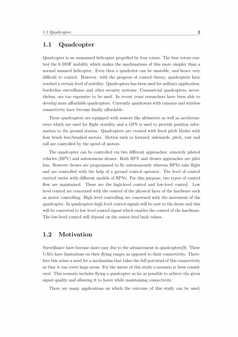
1.1 Quadcopter
Quadcopter is an unmanned helicopter propelled by four rotors. The four rotors con-trol the 6 DOF mobility which makes the machinations of this more simpler than anormal manned helicopter. Even then a quadrotor can be unstable, and hence verydi�cult to control. However, with the progress of control theory, quadcopters havereached a certain level of stability. Quadcopters has been used for military application,borderline surveillance and other security systems. Commercial quadcopters, never-theless, are too expensive to be used. In recent years researchers have been able todevelop more a�ordable quadcopters. Currently quadrotors with cameras and wirelessconnectivity have become finally a�ordable.
These quadcopters are equipped with sensors like altimeters as well as accelerom-eters which are used for flight stability and a GPS is used to provide position infor-mation to the ground station. Quadcopters are created with fixed pitch blades withfour brush less/brushed motors. Motion such as forward, sidewards, pitch, yaw androll are controlled by the speed of motors.
The quadcopter can be controlled via two di�erent approaches: remotely pilotedvehicles (RPV) and autonomous drones. Both RPV and drones approaches are pilotless. However drones are programmed to fly autonomously whereas RPVs take flightand are controlled with the help of a ground control operator. The level of controlexerted varies with di�erent models of RPVs. For this purpose, two types of controlflow are maintained. These are the high-level control and low-level control. Lowlevel control are concerned with the control of the physical layer of the hardware suchas motor controlling. High level controlling are concerned with the movement of thequadcopter. In quadcopters high level control signals will be sent to the drone and thiswill be converted to low level control signal which enables the control of the hardware.The low-level control will depend on the sensor feed back values.
1.2 Motivation
Surveillance have become more easy due to the advancement in quadcopters[9]. TheseUAVs have limitations on their flying ranges as opposed to their connectivity. There-fore this arises a need for a mechanism that takes the full potential of this connectivityso that it can cover large areas. For the intent of this study a scenario is been consid-ered. This scenario includes flying a quadcopter as far as possible to achieve the givensignal quality and allowing it to hover while maintaining connectivity.
There are many applications on which the outcome of this study can be used;
1.3 Thesis Contribution 3
quadcopters be used as surveillance during public events and demonstrations, disastermanagement, damage assessment, recovery operations, border surveillance and relayfor ad hoc networks [1][2][6]. Even though there are functions that necessitate theneed for quadcopter network exist, the technology of quadcopters are still in its veryearly stage and significant improvements needs to be done on quadcopter networks.
Even the capability of a single UAV is limited. Coordination and collaboration ofmultiple small UAVs can create a system that can stretch beyond the capability ofonly one UAV. The multi small UAVs has its advantages over using one large UAV.In a multi UAV system, one of the important problem faced is controlling the UAVand maintaining its communication link when stretching the distance from the basestation. Therefore, when the number of UAVs used increases maintaining connectivitybecomes vital. E�cient network architecture has to be considered to resolve thisissue. Dynamic environment changes, UAV movements and terrain structures are fewfactors that has made maintaining communication with the base station become moredi�cult. Also, if UAVs moves out of the communication range, the ground controllerwill lose the ability to control the drone. Therefore, this raises the question on how tomaintain the network topology whilst moving. The primary focus of this study is tomaintain the network whilst increasing the flying range between each communicationlinks.
This gives us a clear picture that our proposed solution is not only applied forsurveillance but can also be applied to the multi hop network to maintain relay com-munication. Our main motivation is to ensure the link quality is maintained so infor-mation can be sent to the base station from the the furthest point away.
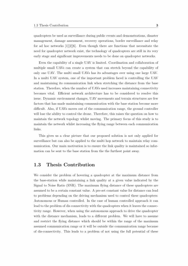
1.3 Thesis Contribution
We consider the problem of hovering a quadcopter at the maximum distance fromthe base-station while maintaining a link quality at a given value indicated by theSignal to Noise Ratio (SNR). The maximum flying distance of these quadcopters areassumed to be a certain constant value. A pre-set constant value for distance can leadto problems depending on the driving mechanism used to control these quadcopters:Autonomous or Human controlled. In the case of human controlled approach it canlead to the problem of dis connectivity with the quadcopters when it leaves the connec-tivity range. However, when using the autonomous approach to drive the quadcopterwith the distance mechanism, leads to a di�erent problem. We will have to assumeand restrict the flying distance which should be within the range of the maximumassumed communication range or it will be outside the communication range becauseof dis-connectivity. This leads to a problem of not using the full potential of these

1.3 Thesis Contribution 4
quadcopters or loosing the control of the quadcopter. Therefore, flying the quadcopterat a maximum distance depends on factors; transmission power of the transmitter, freepath loss, background noise, antenna type and signal propagation.
The main contribution of this study are :
1. Propose a novel solution to maximize the flying distance by combining, au-tonomous driven and link aware cognitive based controller.
2. Analyze and discuss on how to control the link aware based mobility
3. A self-learning mechanism is used to adapt and learn the SNR granularity in agiven deployed environment
4. This solution can be used on existing quadcopters without any additional hard-ware
1.3.1 Aims and Objectives
In a surveillance maintaining link with the quadcopter is a vital need. Therefore de-signing, e�ciency and reliable network are vital issues to be solved. However makingthis network to be autonomous will be a more challenging feat. In this thesis wepropose a novel approach to devise a cognitive based controller to maintain the com-munication link by an autonomous high level control mechanism between the nodes.Hence, the study will detail on small quadcopter. These quadcopter could o�er meansof connectivity without any radio infrastructure; this can be used on remote areas inscenarios where network connectivity is disabled. In addition, the quadcopter will becontrolled by an high level controller with the purpose of maintaining connectivityand being autonomous[3]. This study will focus on the scenario of random mobilitymodel. where in this case the quadcopters doesn’t move in a pre defined path ratherit will be either random or autonomous.
Figure 1.1 illustrates mobility of the UAV, relative to the base station. In thiscase we can consider this movement in spherical because of its 3 DOF translation andconsidering omni directional antennas. Yet a suitable restriction has be considered ofits mobility since node mobility is one of the concerns of link breakage. Therefore acontrolled node mobility is need.
1.3 Thesis Contribution 5
Figure 1.1: Relative spherical movement of quadcopter
1.3.2 Research Question
Maintaining communication link while increasing the flying range is a challenging task.Because quadcopter operates in a very high dynamic environment where environmentconditions might change rapidly and also high node mobility is factor to be concerned.In this study, we will focus on a solution to create an autonomous drone, which movesits self to maintain the link. Therefore the main questions of this study would be on“How to maintain the radio link quality whilst maintaining the flying range”. In herewe are trying to create a cognitive based controller1 to solve this problem. Thereforethis arise a question on “How to model the SNR granularity opposed to the distanceas a prior knowledge for the cognitive control”.
1.3.3 Scope and Limitations
This study will not consider the situation of the survivability of drones. The scopeof this thesis is limited to maintain connectivity and will not consider the situationon how to connect the network if the quadcopter move away from the range. Themain focus is to maintain the network without breaking it. For this study Wi-Fi isused as the communication medium since high throughput is needed. O� the shelfquadcopter AR Drone 2.0 is used for the experiments. This quadcopter has four brush-less motors, control board, sensors, GPS and two cameras. AR Drone 2.0 supportsemergency stop function to ensure safety and will lock the propellers in case it touchesa body. The control board support low level stability control. this quadcopter is Wi-Fiad hoc enabled. where controlling and data transmission is sent through the Wi-Finetwork[4].
1http://wiki.ldv.ei.tum.de/tiki-index.php?page=5.+Cognitive+Control+-+An+example+of+Cognitive+Dynamic+Systems

1.4 Organization of Thesis 6
1.4 Organization of Thesis
• Chapter 2 : Provides a background of UAVs, signal quality metrics and literaturereview on the problem domain. This chapter also describes the techniques thatgoing to be used throughout the thesis.
• Chapter 3 : Provides an in depth description of the design and the reason forusing each modules and explanation on the derivation of the equations.
• Chapter 4 : Describes the implementation and the problem faced.
• Chapter 5 : Describes the reason for choosing each assumption by providingjustifications, validation. This chapter also describes evaluation of the controllerdesign.
• Chapter 6 : Describes the drawbacks of the controller and discusses on how tomitigate such problems
• Chapter 7 : Describes the contribution of this study and suggests future work.

Chapter 2
Background
A comprehensive review on literature has been done on this problem domain. Back-ground and terminology has been explained to increase further understanding of theproblem domain. Finally on this chapter a conclusion has made about the most suit-able signal metric to measure the quality.
2.1 Unmanned Aerial Vehicles
UAVs can be categorized into two kinds; they are fixed wing UAVs and rotary wingUAVs[5]. Fixed wing UAVs are similar to an aircraft which needs a runaway to takeo� and land. In contrast to a fixed wing UAVs, rotary wing UAVs are capable oftaking o� and landing without a runaway. Rotary wing UAVs are more similar to ahelicopter. In a helicopter a tail rotor is used to prevent the helicopter from spinningin order to achieve more stability.Whereas, with a rotary wing UAV a pair of rotorswith a configuration of four, six or eight rotors to spin in opposite direction achievesthe same desired outcome seen in a helicopter.Their capability to fly at a higherrange without much infrastructure or space for deploy, their high mobility to fly abovecrowds, obstacles and places where people cannot go including the low cost makethese types of UAVs more suitable for addressing key issues on surveillance. Rotarywing UAVs can also provide a video transmission of the scenario when needed. Incomparison to fixed wing UAV these provide better stabilized video transmission asfixed wing UAVs is unable to stay in one place[5, 7].

2.2 Signal Quality Measurement Metrics 8
Figure 2.1: A: rotary wing UAV, B : fixed wing UAV
2.2 Signal Quality Measurement Metrics
In this section, terms such as RSSI, SNR and SINR are being delved into. These arethe most commonly used signal metric to measure the signal quality. Their definitionsand the pros and cons of these metric are discussed.
2.2.1 Received Signal Strength Indicator (RSSI)
Wi-Fi devices transmit data by radiating signal energy. This is known as EquivalentIsotropically Radiated Power(EIRP). This output can be amplified by high gain an-tennas. Most WLAN devices use omni directional antennas. This led to an averagegain compared to the gain from directional antennas.
This transmitted signal is a�ected by path loss. This happens due to power lossover the air. Therefore, with distance the signal strength decreases. The signal can alsobe a�ected by signal transformation on the environment due to multi path propagation.Hence, this creates constructive and destructive interferences. This interference canminimized if the line of sight is high without any obstacles. With these traversals, thereceived signal at the receiver is the ’receive sensitivity’. The logarithmic scale of thismeasurement is indicated by Received Signal Strength Indicator(RSSI)1.
The RSSI can be used to indicate the signal quality. However, this measurementdoes not indicate the level of signal as opposed to interference or noise. ThereforeRSSI does not provide a suitable feedback to the user regarding the performance ofWi-Fi.
1http://www.celtrio.com/support/documentation/coverazone/2.0.1/basics.sensitivity.html

2.2 Signal Quality Measurement Metrics 9
2.2.2 Signal to Noise Ratio (SNR)
SNR is the ratio between signal level and background noise level. This can be con-sidered as a di�erence between received signal strength and noise level when the unitsare in decibels.
As shown in Figure 2.2. if RSS is close to noise level then data corruption is high.However, the SNR does not indicate the level of interference. This interference level isembedded within the signal therefore we cannot di�erentiate the interference withinthe SNR. However, if the line of sight is high then the level of interference is reduceddrastically and in such case SNR can be used.
2.2.3 Signal to Interference plus Noise Ratio (SINR)
SINR is the better indicator for measuring the performance of a Wi-Fi system com-pared to SNR or RSSI. This indicates the signal strength as opposed to interferenceand noise. SINR can be increased by increasing the signal strength or decreasing eitherinterference or noise level. Figure 2.2 indicates how SINR can be calculated.
Figure 2.2: Illustration of RSSI, SNR and SINR
SINR is a very complex model. In order to measure the interference the distanceto the other node points is needed for the calculation2. If the nodes are moving thisis not a feasible calculation then a continuous distance calculation has to be donebetween all nodes for each packet.
2http://en.wikipedia.org/wiki/Stochastic_geometry_models_of_wireless_networks

2.3 Literature Survey 10
2.3 Literature Survey
In a radio link, there are di�erent factors that decides the communication range :
• Line of sight propagation properties
• Hardware availability
• Node Mobility.
These factors impact the reliability, latency and throughput of a radio link. However,in a communication link, aerial dynamic and mobility of the quadcopter have a hugeimpact on the performance of the wireless link. This is because quadcopters are ableto move in a high speed and a sudden change in signal could take the quadcopter o�from the communication range. Therefore a controlled mobility mechanism is needed.Additionally, the frequency band used for the communication has a significant impacton the communication range and data rate. For the purpose of this study we will beusing IEEE 802.11 a/b/g band for communication. This band has a high interferencerate and high usage. This is because most devices used in our daily lives use thisband for communication[10]. This shows that interference level for this band is high.Hence, a controlled mobility is needed to control these quadcopters to operate themwithin the range.
We will look into how researchers have solved the problem of maintaining the linkwith the base station while increasing the range.
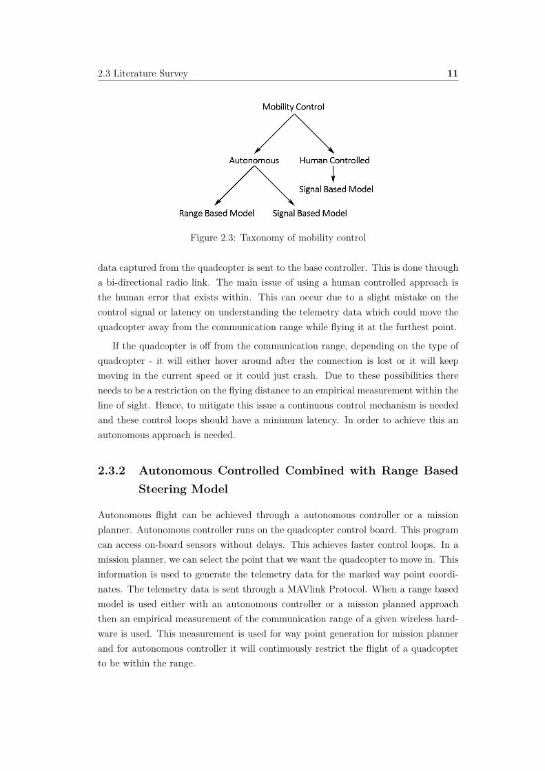
First, we will look into how current mobility control works. This has been illus-trated in Figure 2.3. There are two unmanned approaches to control the quadcopter.The two approaches are autonomous control and Human control approach(RPV).
In most cases, human controlled approach use signal based model and autonomousmodel uses range based model and signal based model to control the quadcopter.
Figure 2.3 Provides a simplified picture on how current mobility control model isused to fly within the communication range.
2.3.1 Human Controlled Combined with Signal Based Steer-ing Model
Currently most of the COTS quadcopters supports human based controlled approach.The controlling of this quadcopter can be performed via a remote controller. However,this controlling mechanism restrict its range of flying because the range of flying needsto be within the sight of the user. The telemetry data is sent to the quadcopter and the
2.3 Literature Survey 11
Figure 2.3: Taxonomy of mobility control
data captured from the quadcopter is sent to the base controller. This is done througha bi-directional radio link. The main issue of using a human controlled approach isthe human error that exists within. This can occur due to a slight mistake on thecontrol signal or latency on understanding the telemetry data which could move thequadcopter away from the communication range while flying it at the furthest point.
If the quadcopter is o� from the communication range, depending on the type ofquadcopter - it will either hover around after the connection is lost or it will keepmoving in the current speed or it could just crash. Due to these possibilities thereneeds to be a restriction on the flying distance to an empirical measurement within theline of sight. Hence, to mitigate this issue a continuous control mechanism is neededand these control loops should have a minimum latency. In order to achieve this anautonomous approach is needed.
2.3.2 Autonomous Controlled Combined with Range BasedSteering Model
Autonomous flight can be achieved through a autonomous controller or a missionplanner. Autonomous controller runs on the quadcopter control board. This programcan access on-board sensors without delays. This achieves faster control loops. In amission planner, we can select the point that we want the quadcopter to move in. Thisinformation is used to generate the telemetry data for the marked way point coordi-nates. The telemetry data is sent through a MAVlink Protocol. When a range basedmodel is used either with an autonomous controller or a mission planned approachthen an empirical measurement of the communication range of a given wireless hard-ware is used. This measurement is used for way point generation for mission plannerand for autonomous controller it will continuously restrict the flight of a quadcopterto be within the range.

2.3 Literature Survey 12
M.Asadpour,et al [8] proposed a solution to use on multi UAV system with an onair ad hoc network. Author states that one quadcopter takes the video and relays thevideo feed via multi hop Wi-Fi ad hoc quadcopter network. However, each of thesequadcopters are maintained by way points. A presumed distance for range is usedfor generating the telemetry data and this control data is sent through the zigbeeprotocol. This solution can be used as surveillance in small scale areas. This approachhas limitation on the flying range since each quadcopter is individually limited to anassumed range. Therefore, using a range based model will restrict the full potential ofthese quadcopters or could make the quadcopter fly o� from the communication range.Because if the noise level is high on the deployed environment then the presumed valuewill be higher than the range. Therefore an autonomous model combined with rangebased model is more suitable to applications where real time data is not needed or toflight within a short distance.
The range of these radio links will decrease depending on the terrain structure, nodepositions, communication characteristics, physical layer (wireless medium) [11].An ob-ject in the environment will attenuate, refract and reflect the signal. This mightdegrade the range of a wireless medium. Therefore using a range based model tomaximize coverage in an unknown terrain is not suitable.Thus, this leads to the needfor an autonomous controller combined with signal based steering model.
2.3 Literature Survey 13
2.3.3 Autonomous Controlled Combined with Signal BasedSteering Model
Research SignalMetric
Signal GranularityControl
Controller Vehicular Type
C.Dixon, etal.[2009][12]
SNR ES with Gradientbased Controller
ESController
Robots whichmoves forwardand Backward
Kam, KhimYee[2008][13]
SNR ES with Gradientbased Controller
ESController
Fixed WingUAV
P. Freitas, etal.[2010] [14]
RSSI - - UAV
R.Rohde,etal.[2010] [15]
Amount ofpersistentconnec-
tions
Neighbor Repellenceand OverlayMovement
- UAV
K.Daniel,etal.[2010][16]
RSSI Node Repellence,Cluster Breathing,
Cluster Fusion
Cognitivebased
Controller
Quadcopter
N.Goddemeier,etal.[2010][17]
RSSI Cluster Breathing - Quadcopter
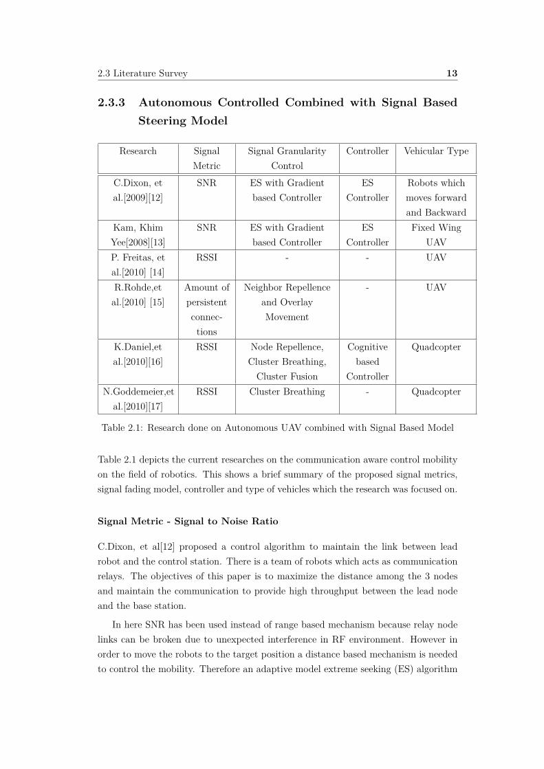
Table 2.1: Research done on Autonomous UAV combined with Signal Based Model
Table 2.1 depicts the current researches on the communication aware control mobilityon the field of robotics. This shows a brief summary of the proposed signal metrics,signal fading model, controller and type of vehicles which the research was focused on.
Signal Metric - Signal to Noise Ratio
C.Dixon, et al[12] proposed a control algorithm to maintain the link between leadrobot and the control station. There is a team of robots which acts as communicationrelays. The objectives of this paper is to maximize the distance among the 3 nodesand maintain the communication to provide high throughput between the lead nodeand the base station.
In here SNR has been used instead of range based mechanism because relay nodelinks can be broken due to unexpected interference in RF environment. However inorder to move the robots to the target position a distance based mechanism is neededto control the mobility. Therefore an adaptive model extreme seeking (ES) algorithm

2.3 Literature Survey 14
is proposed to control the motion of the relay nodes. In here the ES model is moresimilar to a bicycle-like kinematics that can only be used on vehicles that can moveforward and backwards. ES methods are applied to gradient based controllers to get areal time estimate on SNR gradient. Extreme seeking controller is an adaptive controltechnique which uses the gradient of a given cost function. In this case it uses SNR.By using SNR as the cost function the model drives the plant to an optimal position.This proposed model is an abstract model for robots that moves on one axis[12].
Kam, Khim Yee[13]proposed a solution to increase the flying range and to sendreal time data back to the command station. In here multiple survey vehicle acts as acommunication relay. This thesis had two main objectives
1. Predicting the signal to noise ratio of the communication link using communi-cation propagation model.
2. Using the predicted SNR as reference to the autonomous control algorithm toreposition them on to the optimal loitering flight path to maximize the qualityof the communication and the range.
ES algorithm is been used with a real-time adaptive controller to create the au-tonomous quadcopter controller to maintain the link . With the continuous feed backthe controller make sure that it achieves the target positions. This approach is similarapproach to C.Dixion[12]. However in this case he has catered the solutions to thefixed wing UAV. Therefore it has the same pros and cons of C.Dixion approach[12].
Using Extreme seeking controller will provide a good result if we want the quad-copter to be move in only one direction. However due wind and other external influenceit could rotate from its current heading. In that case using only single axes will makethe quadcopter to fly in an orbit to reposition it self. Therefore we are in much needof a simplest controller to achieve the needed mobility and take advantage of thequadcopter maneuverability.
Signal Metric - Received Signal Strength Indicator
P.Freitas, et al.[14] proposed a solution on wireless sensor networks, where reliableconnection is needed to maintain the connectivity with the base station

2.3 Literature Survey 15
Figure 2.4: Scenario on a quadcopter ad hoc network [14]
Figure 2.4 illustrates a scenario in a ad hoc network. In part (1), node3 D isbounded within the range of B and C. Therefore it can randomly move among thoseranges. However in part (2) the link between node C and D is broken and node D isonly bound within the range of node B. Part (3) illustrates the scenario where node Dis going o� the range from node B and part (4) shows us that the link is broken. Thisfigure gives us a clear picture that a node can be moved freely as long as its boundedwith more than 1 node. However in case of a single link a controlling mechanismis essential to maintain the link within the node. Similarly even node A should bemaintained within the range of base station.
Therefore in order to maintain the overall network topology, single links betweenthe nodes have to be maintained, so that it can be applicable for the overall mainte-nance of the ad hoc network. There are two types of individual links to be consideredThese are:
1. Link Between Base station and UAV
2. Link Between UAV and UAV
In order to maintain these two links the author proposed a simple algorithm by makingthe UAVs to track the connected adjacent node. When there is only one link to bemaintained, then depending on the RSSI value, it either moves towards or move awayfrom the adjacent node[14]. In this paper the author has proposed an algorithmto solve the problem of disconnectivity. Still in a cyber physical system having a
3In here node represents a single UAV

2.3 Literature Survey 16
deterministic model will not solve the problem rather a controller design is needed tomaintain the connectivity.
In contrast to P.Freitas, et al[14], K.Daniel,et al. proposed a controller design [16]that uses a channel aware mobility model to control the mobility of UAV clusters.In this a steering algorithm is designed based on overlay movement(OM), clusterbreathing(CB), node repellence(NR), cluster fusion(CF). This steering algorithm isused to maintain the inter drone links.
Figure 2.5: A control loop design to control MUAV
Figure 2.5 illustrates the proposed controller design. A reference RSSI is givenas a input to the mobility control. In here, 3 individual separate model Node re-pellence(NR), Cluster breathing (CB), Cluster fusion (CF) is used to calculate thesteering vector. NR is used for avoiding collision between the neighbor nodes, CB isused for maintaining the connectivity while considering the spacial coverage and CFmaintains the coherence of the clusters. With the output from steering vector, overlaymovement addresses the motion to the given target area. In here overlay movementacts independent to the RSSI value. Therefore overlay movement (OM) aims to movethe UAV to the given target. While moving RSSI restricts the movement to maintainthe mesh topology. This is handled by a control loop that continuously tries to drivethe UAV to the target or to achieve the maximum distance. This solution is morecatered to manage the cluster rather focusing on single link individually. In this theauthor hasn’t stated any practical implementation rather has proposed this by using asimulation. When we consider a controller design, real world experiments are in needbecause there are many factors that impacts the node mobility.
N.Goddemeier,et al[17]. proposed an experimental testbed to analyze the behaviorof the communication aware based controller . For this RSSI based communicationaware steering algorithms is been used. Figure 2.6 illustrates a simple outdoor scenario.In this the distance changes depending on the environment interferences. Communica-tion aware algorithm will be able to identify this interference and steers the quadcopterto the next point of target while maintains the connectivity.

2.3 Literature Survey 17
Figure 2.6: Scenario of a RSSI based model[17]
The mobility on this approach uses the cluster breathing algorithm. This modelcompares the reference RSS to the actual RSS and then decides whether to movethe quadcopter to either towards, away or loiter. In order to test this framework asimulation is used on the drone to find the reaction . Still in this the authors haven’tevaluated this approach on a physical world.
In both the above studies have used RSSI as a signal metric. However RSS providesthe information about the signal level on the physical layer though this doesn’t ensurethat the communication can be done. Because for an example the noise level could behigher than the signal level and in that case the throughput will be low. Therefore abetter metric has to be considered.
Signal Metric - Amount of persistent connections
R.Rohde, et al[15]. proposed a solution for aerial sensor networks. In this the UAVs aredeployed in a mesh protocol. The authors have used amount of persistent connectionsfor a node as a metric. With this metric they have maintained the connectivity byconsidering all the links for a node. However, the motion of each node depends onchannel characteristics. RSSI measurements of each links are broadcast and with thiseach node steers its motion to keep the mesh network alive. In here for each link inthe mesh network neighbor repellence and overlay movement is used to control themobility. Neighbor repellence for each node concerns of the closest node and tries toavoid it by using RSSI to get the appropriate distance. Depending on this distancesteering force is calculated. And by using neighbor repellence the nodes either seeks,stays or flees. The overlay movement uses a seek movement to reach a specific targetarea. This solution is more catered to a mesh networks and this cannot be used ina scenario where we have to consider a single link. In here distance is calculatedusing the RSSI values. If its a dynamic changing environment that is influenced by
2.4 Techniques that used on this project 18
interference and noise then this will give inaccurate results.
2.3.4 Summary
Communication aware based steering concept is already been used on the robotics.Still from our knowledge on the literature there aren’t any practical implementation onquadcopter [16, 17]. However K.Daniel,et al[16] solution is catered to the quadcopterto quadcopter link. It is based on mesh network and uses RSSI as a metric. And onN.Goddemeier,et al[17] solution, it is more focused on the experimental test bed rathera real world implementation. Therefore both K.Daniel,et al[16] and N.Goddemeier,etal[17] solutions are deterministic and in simulation it could provide a good result yetin a CPS having a deterministic model doesn’t ensure that it will be same becausesensors are error proned. This shows us the vital need of a autonomous controller tomaintain the link quality.
Most of the research on the signal based steering model have used either SNR orRSSI. In Table 2.1 the researchers have considered the scenario on sending real timedata back to base station or to maintain the link between adjacent node. Thereforeif we want only to maintain the link then RSSI will be suitable metric because RSSIdetermines the quality of signal. However when looking at the scenario on sending realtime data to the base station, then we have to consider the data rate. If we need higherdata rate and operation range then signal level should be very high compared to thenoise level. This will increase SNR and SINR value. Therefore if we want higher datarate and fewer retransmissions error then SNR or SINR are suitable metric. HoweverSINR is very complex model to be used within a quadcopter because quadcopter isa resource constrained environment. Quadcopters has a very good line of sight withbase station since it flies in very high altitude. Therefore the amount of interferencecan be low in a open space. Therefore SNR is a suitable metric to measure thesignal quality for the purpose of this study.
2.4 Techniques that used on this project
2.4.1 Signal Propagation
A wireless transmission degrades by several factors, among the most commons are[18, 19].
1. Distance dependent path loss
2. Electronic Interference
2.4 Techniques that used on this project 19
3. Thermal Noise
4. Physical Obstacles
5. Bandwidth use
Most literature on communication aware motion controlling does not consider thesefactors. They tend to go for an suitable model to approximate it by either withdistance-dependent path loss or fading with distance-dependent path loss.
In the case of distance-dependent path loss model it is been assumed that there arestrong line of sight is available. This means that there isn’t any fading in the signal.Therefore the signal degradation can be be model in a function of distance. How everthis is not suitable, because noise is factor to be concerned.
However if we use the distance dependent path loss model with fading then we tendto move to a probabilistic approach to model the changes. In this case we have toconsider about the small scale and large scale fading. With that the average of fadingis used to create a distance dependent path loss with fading model[18]. Thereforemost of the research tends to go with this model to find the signal gradient. Yetthe problem is due to dynamic environment changes, parameters on this model willchange. Therefore this will not be feasible for physical experiments for the purpose ofquick deployment.
2.4.2 AR Drone 2.0
AR Drone is a quadcopter which will be used for this study. The technical specificationof the device is listed below[4]:
• 1GHz 32 bit ARM Cortex A8
• Linux 2.6.32
• 1GB DDR2 RAM at 200MHz
• Wi-Fi b g n
• 3 axis gyroscope 2000°/second precision
• 3 axis accelerometer +-50mg precision
• 3 axis magnetometer 6° precision Pressure sensor +/- 10 Pa precision
• Ultrasound sensors for ground altitude measurement - up to 5 meters
2.4 Techniques that used on this project 20
AR Drone has an on-board Wi-Fi card. This can be controlled by either smartphone/tablet application or it can be controlled from a PC with a joystick. AR Dronehas the auto pilot capability, from which take-o� and land is been done. The ARdrone runs on a busy box version of Linux distribution. The internal software takescare of the auto pilot. Initially the AR Drone runs on a ad hoc mode which is thedefault mode on the AR Drone. In the ad hoc mode, a device can get connected to thedrone to communicate with it. The communication is done through 3 UDP channels .This is used to send the navigation data, control signal and the video feed. Navdatachannel provides the drone navigational, sensory data and controller parameters as afeed back. Control channel is used for the user to give control command signal throughAT format to the drone. This control signal should be sent on less than or equal to30Hz.
2.4.3 Navigation model
In this section we will discuss on how quadcopter/ardrone navigation model operates.Since it will be the basics for understanding of modeling flight dynamic to design flightcontroller.
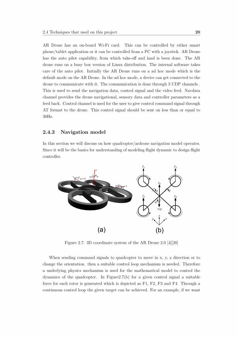
Figure 2.7: 3D coordinate system of the AR Drone 2.0 [4][20]
When sending command signals to quadcopter to move in x, y, z direction or tochange the orientation. then a suitable control loop mechanism is needed. Thereforea underlying physics mechanism is used for the mathematical model to control thedynamics of the quadcopter. In Figure2.7(b) for a given control signal a suitableforce for each rotor is generated which is depicted as F1, F2, F3 and F4. Through acontinuous control loop the given target can be achieved. For an example, if we want
2.4 Techniques that used on this project 21
to fly the quadcopter in vertical direction then we have to equally move the speedof all 4 rotors which will increase the thrust equally, if the total force is more thanthe gravity then it will slowly ascend. Similarly by changing the speed of 4 motorswe can descend, turn left, turn right, move forward and backwards. This is the basicprinciple of a low level controller on a quadcopter. In thesis we will talk about thecontroller design while considering the coordinate system of AR Drone as shown inFigure 2.7(a).
2.4.4 PID Controller
In Control theory, PID is the most used controller design on closed loop system. Thisis the most common feedback controller to be used. PID is a combination of logic,functions and blocks.
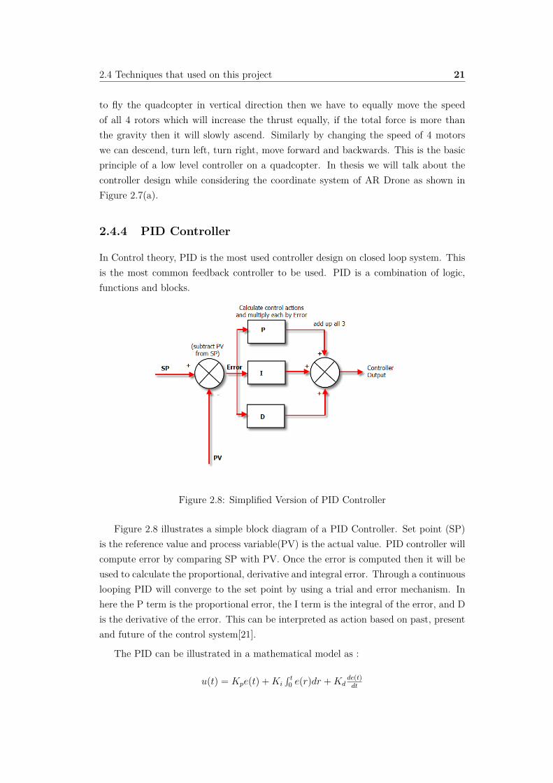
Figure 2.8: Simplified Version of PID Controller
Figure 2.8 illustrates a simple block diagram of a PID Controller. Set point (SP)is the reference value and process variable(PV) is the actual value. PID controller willcompute error by comparing SP with PV. Once the error is computed then it will beused to calculate the proportional, derivative and integral error. Through a continuouslooping PID will converge to the set point by using a trial and error mechanism. Inhere the P term is the proportional error, the I term is the integral of the error, and Dis the derivative of the error. This can be interpreted as action based on past, presentand future of the control system[21].
The PID can be illustrated in a mathematical model as :
u(t) = Kpe(t) + Ki
s t0 e(r)dr + Kd
de(t)dt
2.4 Techniques that used on this project 22
In here the Kp is the proportional gain,Ki is the integral gain and Kd is thederivative gain e is the control error and u is the control signal. Depending on theparameters Kp,Ki,Kd, we can create di�erent flavors of controllers. For example ifKi = 0 then control signal will only depend on the proportional and integral gain.This is known as PD controller.
2.4.5 Kalman Filter
Kalman filter is a technique to estimate the state of a system using sensor and observedmeasurements which contains random errors. Kalman filter is been used extensivelyon applications particularly on autonomous. This is developed in the late 1950’s.This has a set of mathematical equations which only requires a few matrix operationsfor each step. Therefore this is a very e�cient model. This model uses Bayes filterwith continuous states. In which the states are represented in normal distribution. Inhere the estimations support past, present and future state estimation[22].The modelis only applicable for the model that is governed by the linear stochastic di�erenceequation.
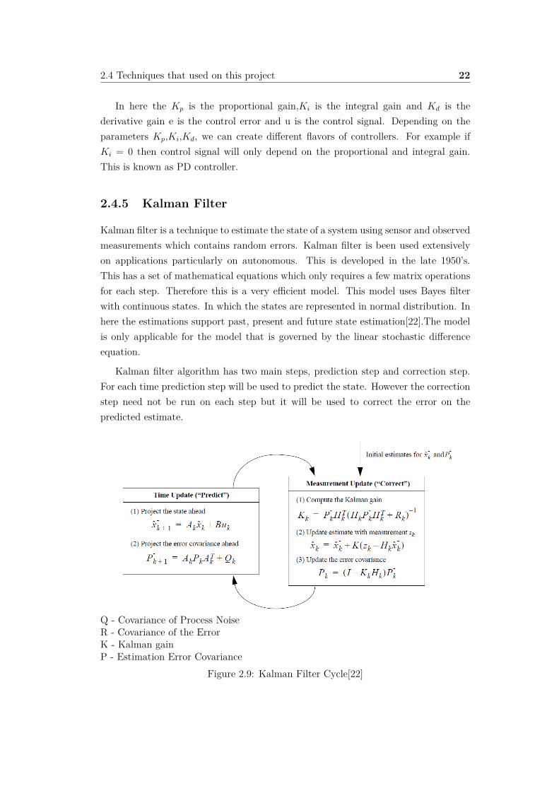
Kalman filter algorithm has two main steps, prediction step and correction step.For each time prediction step will be used to predict the state. However the correctionstep need not be run on each step but it will be used to correct the error on thepredicted estimate.
Q - Covariance of Process NoiseR - Covariance of the ErrorK - Kalman gainP - Estimation Error Covariance
Figure 2.9: Kalman Filter Cycle[22]

2.4 Techniques that used on this project 23
On the Figure 2.9, equations on time update is the motion model. This is theprediction step on the Kalman filter algorithm. In here the first equation illustratesthat a given estimation depends on the previous estimation and the control signal. thesecond equation illustrates the uncertainty of the state. These two equations are usedto estimate the current state and project the error covariance. This error covarianceis the prior estimate for the next time step.
In correction step, first we have to compute the Kalman gain. This gain is used toestimate the state with the help of the observed measurement. Observed measurementand motion measurement is used to compute the error. This error correction will bedone and updated on the prediction state.

Chapter 3
Design
This chapter highlights the design steps and the constraints of creating an autonomousand signal sensed steering cognitive control system to maintain the link quality.
The target of the controller design is to achieve the following traits:
Autonomous - moves without external influences(human).
Signal based steering - use SNR as a signal metric to maintain the link
Cognitive - have a thought process to understand the changes in SNR and abilityreact to such changes and achieve the target goal.
Figure 3.1: A simple scenario on flying the quadcopter to achieve the target SNR

3.1 System Architecture 25
3.1 System Architecture
The main idea behind this controller design is to achieve a similar human thoughtprocessing. In such an instance, to achieve a given SNR, a person can use a sensor andif he has prior knowledge then that knowledge can be used to make a decision on wherethe target point is. The person can move faster with the understanding he possesswhile continuously checking the sensor and learning the changes in the environmentto make better decisions on estimating the target position. The cognitive behavior ofthe scenario can be illustrated through Figure 3.2.
Figure 3.2: Schematic of a cognitive control system [28]
A Cognitive based model has 5 main components[28]:
1. Perception : extract important data and estimate the state.
2. Actions : acts to be performed on the plant.
3. Learning : learn from the sensors and actions to gain prior knowledge
4. Knowledge : have past information stored to understand the behavior of theenvironment.
5. Cognition (Control) : use prior knowledge and the learning to make decisions.
We have proposed an architecture to achieve the target with underlying principles ofcognitive behavior.The proposed solution has 4 main components. They are :
1. Asynchronous Data Reader and Writer
2. State Estimator
3. Position Controller

3.1 System Architecture 26
4. Low Level Controller
The interaction between these components are depicted on Figure 3.3
Figure 3.3: System architecture for the autonomous controller
Position controller is the core component of this model. The signal controllercontinuously checks if it has achieved the referenced signal metric(SNR). Altitudehold makes certain the quadcopter flies in the given altitude. The low level controlleris considered as a plant1. This is considered as a model that represents the physicalproperties of the quadcopter. The low level controller acts as an open loop control 2
system that takes control signals as input and navigational data will be the output.
In an autonomous controller, having a deterministic model is not su�cient as thereare other concerns such as timing, latency and sensor noise to consider. Therefore,to address these problems we need to consider a suitable architecture. Thus, we haveconsidered the aspect of reading data from sensors that will be controlled by theasynchronous data reader and writer. State estimator will estimate the position of thequadcopter with the data collected while considering the sensor noise.
3.1.1 Low Level Controller
We need to understand the dynamic behavior of the quadcopter in order to designan autonomous controller. We can consider the quadcopter as a plant which takespropeller speed as inputs. However, the quadcopter only knows how much thrust thatneeds to be produced with its motors. Therefore it tries to integrate the current speedto achieve the required speed. This behavior can be modeled as a low level controller.The main object of this low level quadcopter is to maintain the required speed of x,y, z , yaw, pitch and roll. Therefore this can be shown as a controller as depictedin the Figure 3.4. To achieve a required pitch and roll the quadcopter should haveforward (x axis) and sidewards (y axis) speed. Therefore the model can be thoughtas a decoupled model that has an independent x, y, vertical and yaw controller. The
1A plant in control theory, is the combination of process and actuator.2http://en.wikipedia.org/wiki/Open-loop_controller
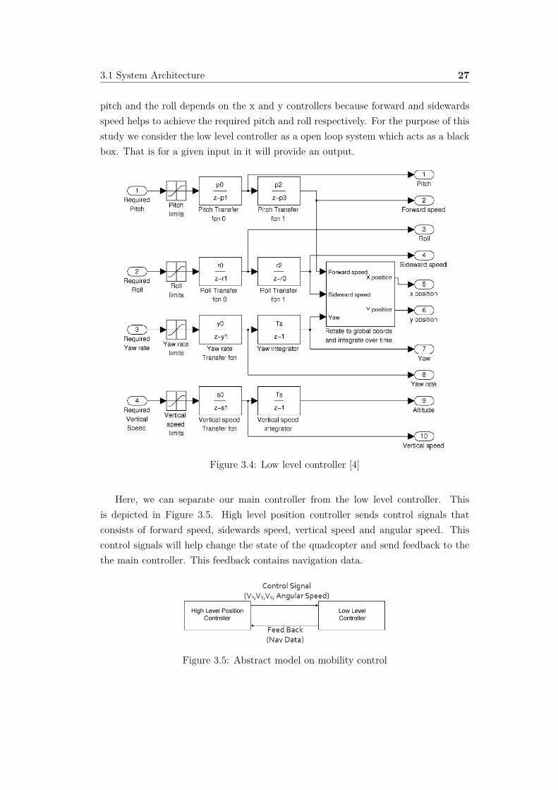
3.1 System Architecture 27
pitch and the roll depends on the x and y controllers because forward and sidewardsspeed helps to achieve the required pitch and roll respectively. For the purpose of thisstudy we consider the low level controller as a open loop system which acts as a blackbox. That is for a given input in it will provide an output.
Figure 3.4: Low level controller [4]
Here, we can separate our main controller from the low level controller. Thisis depicted in Figure 3.5. High level position controller sends control signals thatconsists of forward speed, sidewards speed, vertical speed and angular speed. Thiscontrol signals will help change the state of the quadcopter and send feedback to thethe main controller. This feedback contains navigation data.
Figure 3.5: Abstract model on mobility control

3.1 System Architecture 28
3.1.2 Asynchronous Data Reader and Writer
A data extractor is needed to collect the required navigation data. A suitable archi-tecture is needed to achieve this. Hence, an asynchronous data reader and writer havebeen used. The data writer reads the navigation data from the low level controllerand this is stored on a data store. The data reader reads the data and feeds this infor-mation to the state estimator to predict the current position. Data writer and readerexecutes concurrently. The data loss can be reduced with the use of concurrency. Thismodule acts as a perception module as described on a cognitive control system.
3.1.3 State Estimator
A sensor measurement is most likely to be unreliable due to system noises, softwareand hardware errors. Therefore, a computational e�cient approach is needed to filterthe data. Current yaw, altitude, velocity and GPS data are the navigational data thatwill be used. These data will contain quite noise sensory information. Therefore, afilter mechanism that learns measurements, predicts expected values and also detectanomalies is required.
AR Drone has its own data filter that filters errors on velocity, altitude and yawmeasurements[23]. These estimated data can then be used directly for state estimation.However, there would still be errors and noise in this data. Hence, a suitable designis used to suppress this noise for the prediction of the position estimate.
For the purpose of state estimation we have considered a 3D coordinate system.This is because localizing the quadcopter is a vital need so that the quadcopter canbe kept in control within range. The idea is to have a 3D Coordinate system relativeto the base station. If we depend only on local coordinate system for the quadcoptersthen due to external influence like wind and noise on GPS data, the quadcopter couldindicate a wrong position and heading. Hence, we have used three coordinate systems.They are :
• World coordinate system (world state) : 3D coordinate system relative to thebase station but the north is in Y Axis.
• Base coordinate system (base state): 3D coordinate system relative to base sta-tion. Axis and zero point is considered as the initial placement of the quadcopter.
• Local coordinate system (local state): local coordinate of the quadcopter (Note:see Figure 2.7 for AR Drone 2.0 Coordinate System).
In order to reduce the complexity of the research problem, the movement can beconsidered as a one dimensional problem in a base coordinate system. In reality it

3.1 System Architecture 29
moves in a 3 dimensional on world coordinate system. Therefore, the main intentionis to make the quadcopter move along the X axis in the base coordinate system.
Thus, we considered the initial placement of the quadcopter as the zero point of thebase coordinate system. The quadcopter should be placed close to the base station andthe initial forward direction should be the direction of its flight. Quadcopter’s initiallocal coordinate X, Y, and Z axis will be considered as the the base state. This hasbeen illustrated on the Figure 3.6. From this we can map a three dimension mobilityto a one dimension mobility by making the quadcopter to move along the X axis.Since we are moving the quadcopter through out the line then target y coordinate willalways be zero in the base coordinate system. Yet, due to environment influence itwould drift away from the target.
Figure 3.6: State estimation for the quadcopter
The main target of the state estimator is to estimate the base state by inferringsensor observations and motion actions. Through sensor observations we can estimatethe base coordinate and this can be shown as :
z = h(x) (3.1)
xÕ = g(x, u) (3.2)
In Equation 3.1, z is the sensor reading, h is the observation function and x is theworld state. However in real application we have to infer the real world estimate fromthe sensor reading :x = h≠1(z). For this intent we have used the GPS as the sensorobservation. The position can be directly calculated using the GPS of the quadcopter

3.1 System Architecture 30
and the GPS coordinate of the starting point. And while flying it can calculate itsposition from Equations 3.8 and 3.9.
a = sin�(—Ï/2) + cosÏ1 ú cosÏ2 ú sin2(�⁄/2) (3.3)
c = 2 ú atan2(Ô
a,Ô
(1 ≠ a)) (3.4)
d = Rad ú c (3.5)
In here the ’haversine’ formula is used to calculate the distance between two points.The reason for using haversine formula is that it gives more accurate results for smalldistance3.
Direction is computed along the true north. For this intent forward azimuth isapplied to find the bearing.
◊ = atan2(sin�⁄ ú cosÏ2, cosÏ1 ú sinÏ2≠sinÏ1 ú cosÏ2 ú cos�⁄) (3.6)
Ïis latitude, ⁄ is longitude, Rad is earth’s radius
The above equation returns a value from range of -180 to 180. This can be con-verted to angle from x axis on world space :
◊Õ = �
2 ≠ ((◊ + 2�)%2�) (3.7)
From distance d and angle ◊Õwe can compute the coordinate of the quadcopter in
world space.
PosXx = d ú cos◊Õ (3.8)
PosYx = d ú sin◊Õ (3.9)
(PosXx, PosYx, RotXY x)T is the current state on the world coordinate. InhereRotXY x is the yaw value and this can be directly extracted from the navigationaldata(magneto meter).
3http://mathforum.org/library/drmath/view/51879.html

3.1 System Architecture 31
We cannot only rely on sensor observation because GPS has its own delay and theobservations are noisy4. This leads to a wrong estimation.
To solve this problem we have fusioned GPS data with dead reckoning (“deadreckoning is the process of calculating one’s current position by using a previouslydetermined position and advancing that position based upon known or estimatedspeeds over elapsed time and course.”). Thus we can use motion action (Vx,Vy,Vz) asshow on Equation 3.2 where x
Õ is the current state, x is the previous state, u is theexecuted command and g is motion model for state prediction. Where g integrates themotion commands to estimate the world state. However this will lead to inaccurateresults if we fly for long distance.
Therefore Kalman Filter is used to fuse gps and dead reckoning for state prediction.The motion actions will be used as the prediction model and sensor observations areused as correction steps. However Kalman filter is used for linear system and in herethe quadcopter is a non linear system. Therefore Extended Kalman Filter (EKF) isused to linearized the non linear function.
1. Prediction Step:
µt = g(µt≠1, ut) (3.10)
�t = Gt�GTt + Q with Gt = ”g(x, ut)
”x
----- x=µt≠1 (3.11)
Q is the motion noise covariance this is already known. the covariance � of themotion model is estimated using previous covariance added with motion noise covari-ance.
We are considering the motion in a 2D space with a given altitude. Therefore wecan show Motion Function (x , y , yaw) as:
g(x, u) =
Q
ccca
x + (cos(Â)x ≠ sin(Â)y)�t
y + (sin(Â)x + +cos(Â)y)�t
 + �t
R
dddb (3.12)
G = ”g(x, u)”x
=
Q
ccca
1 0 (≠sin(Â)x ≠ cos(Â)y)�t
0 1 (cos(Â)x + sin(Â)y)�t
0 0 1
R
dddb (3.13)
4http://ardrone2.parrot.com/apps/flight-recorder/

3.1 System Architecture 32
From Equation 3.12, it is clearly visible that motion function is not linear becauseit has cosine and sine in function. This was the reason to choose EKF to linearizethe function. From prediction step the state will be continuously estimated. Howeverdead-reckoning is error prone over time. Therefore the estimated value is correctedusing GPS estimation.
2. Correction Step:
µt = µt + Kt(zt ≠ h(µt)) (3.14)
Equation 3.14 shows that the new estimation depends on previous estimation,Kalman gain(Kt) and current measurement error. Current measurement error cancomputed as zt ≠h(µt). In here zt can be calculated by transforming quadcopter worldstate(GPS data) to local Coordinate and h(µt) is current state of the quadcopter onbase state.
X =Q
a Rx tx
0 1
R
b =
Q
ccca
cos(Âx) ≠sin(Âx) xx
sin(Âx) cos(Âx) yx
0 0 1
R
dddb (3.15)
where Rx is the rotation matrix and tx is the translation vector.
Equation 3.15 is used convert local coordinate system to global coordinate system.Therefore X≠1is computed to transform global coordinate to local coordinate system.
We can use Equation 3.17 with Equation 3.15 to convert world coordinate to localcoordinate system.
RRT =I since R is orthogonal matrix.
zt = X≠1
Q
ccca
≠PosXx
≠PosYx
≠RotXYx
R
dddb =Q
a RxT ≠RxT tx
0 1
R
b
Q
ccca
≠PosXx
≠PosYx
≠RotXYx
R
dddb (3.16)
In here tx is the translation vector and it is a zero vector. therefore :
zt =Q
a RxT 00 1
R
b
Q
ccca
≠PosXx
≠PosYx
≠RotXYx
R
dddb (3.17)

3.1 System Architecture 33
Similarly h(x)can be shown as (convert current quadcopter position to local coor-dinate) :
h(x) =Q
a RxT 00 1
R
b
Q
ccca
≠xx
≠yx
≠Âx
R
dddb (3.18)
From Equations 3.17 and 3.18 current measurement error can be computed (zt ≠h(µt)).
Kalman gain can be computed using equation 3.20.
�t = (I ≠ KtHt)�t (3.19)
Kt = �tHTt (Ht�tH
Tt + R)≠1 with Ht = ”h(x, ut)
”x
-----x=µt
(3.20)
The above equation depends on Ht and R. R is the sensor noise covariance andthis is already known. Ht can be computed from :
h(x) =
Q
ccca
≠xcosÂl ≠ ysinÂx
xsinÂx ≠ ycosÂx
≠Âx
R
dddb (3.21)
H = ”h(x, u)”x
=
Q
ccca
≠cosÂx ≠sinÂx xsinÂx ≠ yxcosÂx
sinÂx ≠cosÂx xcosÂx + ysinÂx
0 0 ≠1
R
dddb (3.22)
We can estimate the current state using the Equation 3.14 after calculating theKalman gain and current measurement error
3.1.4 Position Controller
The main objective of this controller is to fly the quadcopter in a given altitude and toachieve the given SNR. Therefore two controllers is used to achieve these objectives.Position controller is the core of the study. This will move the quadcopter from thebase coordinate X0, Y0 to the base coordinate X1, Y1 while maintaining the given Z
altitude. The target coordinate for horizontal space will be provided by the signalcontroller.

3.1 System Architecture 34
3.1.4.1 Altitude Hold
Altitude hold is used to maintain the quadcopter in a given altitude. Therefore the 3dimensional mobility can be considered as a 2 dimensional problem. A PD controller isused to achieve this objective. This is depicted on Figure 3.7. The integral part is notconsidered on the PID controller because the drone has its own stabilizing mechanismimplemented on the low level controller. The PD controller is used as a trial and errormechanism to converge to the target altitude. The altitude error is computed andwith vertical speed transfer function; the vertical speed will be calculated. This speedis then sent to the low level controller as a control signal to drive the quadcopter. Thetarget altitude can be achieved with a continuous loop.
Figure 3.7: PD Controller for altitude hold[4]
3.1.4.2 Signal Controller
Figure 3.8: Design for the Signal Controller
Figure 3.8 illustrates the basic design of the signal controller. We will be using SNRas the signal metric. The plant only understands the signal in velocity. A suitable

3.1 System Architecture 35
model is in need to transfer SNR to velocity. Distance is the integration of the veloc-ity. Therefore, we have proposed a transfer function and an algorithm to decide thedistance and the direction of the quadcopter to move. Once the target distance anddirection is calculated, a PD Controller is used to move the quadcopter to achieve thetarget position. Below we will look at each components and the reasons for it.
Signal to Noise Ratio (SNR) as signal metric
We are considering the scenario where real time data have to be sent back to the basestation. Therefore a communication link aware mechanism is needed. In Section 2,we have concluded that Signal to Noise ratio is a suitable metric to measure the linkquality. This is because SNR decreases with the distance due to the free space lossand background noise.
SNR = Psignal
Pnoise
(3.23)
SNR is a suitable metric to depict the performance of the wireless connection. Thisis because
1. If signal level is higher than the noise level then it will allow higher data rateand reduce the retransmission errors - Shannon–Hartley theorem5.
2. If noise increases. then Pnoise increase and SNR will reduce. Therefore commu-nication range will decrease.
3. SNR provide the information of the physical layer to the controller.
4. No need of any additional hardware.
Therefore, SNR is a suitable metric to be used to sense changes on the physical layer.
Transfer Function
The main objective of the transfer function is to make the controller to behave as alearning, knowledge and cognition module as described in a cognitive control system.This module tries to learn the change of SNR over distance and uses this knowledgeto make a better decision.
One of the major performance constraints on wireless communication is fading.This is caused due to multiple factors as mentioned in Section 2.4.1. Due to these
5http://en.wikipedia.org/wiki/Shannon%E2%80%93Hartley_theorem

3.1 System Architecture 36
Algorithm 3.1 Modeling Transfer functionStep 1: Send the quadcopter to fly in a direction to collect SNR vs DistanceStep 2: Plot the data x:SNR, y: DistanceStep 3: Regression over the dataStep 4: Get the Coe�cients and create a SNRDM
factors, a small change can introduce either a small or drastic change on signal quality.This change can be continuously detected by the SNR value.
Understanding the change of signal to noise ratio in this space is a vital importanceon this study because this information is used as the knowledge module on cognitivesystem. As mentioned in Section 2.4.1 there are no direct methods that can be foundthat depicts the signal change as opposed to the distance. Therefore, we have proposeda learning mechanism to solve this issue. The quadcopter is sent for a reconnaissanceto a given direction and for the given altitude with this test run SNR vs distance datafor a given environment is collected. Using polynomial regression, a machine learningapproach is used to create a model to approximate the signal gradient. The gathereddata is used for the the initial estimation to create a map on signal changes withthe distance. This map is called as SNRDM - (SNR to Distance Map). While flyingSNRDM is updated with the current changes. However for the flights without initialestimation for SNRDM will use a small step size to converge to the target. Yet thiswill take long time to achieve the target(Section 5.5.3). In a quadcopter system flyingtime is an important factor to be concerned. Therefore using such learning mechanismcan make the convergence faster than having a small stepping size. Therefore usingthis approach will make the quadcopter move towards the target position quickly.
In this study we assumed that rate of change on signal in a line will be the sameon di�erent flights. However this assumption is not suitable for a practical scenariowhere fading will vary depending on multiple factors. However, we need this modelonly to give an approximate value as a prior knowledge . We can also consider thisassumption to be valid if we are able fly the quadcopter through the line and reducethe impact of the external force by increasing the withstanding ability.
Algorithm 3.1 illustrates the steps to be proceed to create a transfer function model.For the purpose of regression, we have considered a 1/x based model. This is becausewith the distance SNR decreases. Therefore we can model this as :
d Ã3 1
SNR
4–
(3.24)
However we cannot say what is the rate of change with distance. Therefore, finding– will be a challenging task. Since the main purpose of this model is to approximatethe environment change. Therefore we have to assume the – to a constant because

3.1 System Architecture 37
increasing –will be computationally expensive. Once the coe�cients are found then aSNRDM will be created for the range of minimum SNR to maximum SNR.
SNRDM will be considered as a initial map and this is an array, in which the indexwill be the SNR and value will be the distance. On fly the SNR vs distance datawill be collected and from this data the map will be updated. Main objective of thetransfer function is to simulate the behavior of the knowledge and learning module oncognitive control system. These modules will be analyzed on chapter 5.
Direction Algorithm
An algorithm is used to calculate the direction of the flight.
Algorithm 3.2 Algorithm to find the flight directionIf SNR < Reference SNR:
MoveTowardsTheBaseStation()Else SNR > Reference SNR:
MoveAwayFromBaseStation()Else
Hover();
The direction of the the flight will be calculated using the magneto meters whichis on world space. These values are then converted to the base coordinate system.
Motion Controller
Once the distance(d) and direction(⁄ (+: move away/-: move towards) ) is found wecan calculate the target x, y and yaw to be achieved. This scenario can be illustratedwith Figure 3.9.
currentstate = (xt, yt, Ât)T (3.25)
targetstate = ((((xt)2 + (yt)2)1/2) + (⁄ ú d), 0, Âs)T (3.26)
Âsis the target orientation.

3.1 System Architecture 38
Figure 3.9: Calculates the target position for the next step
From the above model we can infer the values for the x,y and yaw axis.
The Equation 3.26 can be further understood with the Figure 3.9. The quadcopterdrifts away from the target. However, the SNR of the current position can be achievedin the same distance along the x axis. This assumption is true for the same radiuswith small ◊. The ◊ will decrease with the withstanding ability of the quadcopterbecause it will be more stable to environmental influences and will minimize the drift.Using this assumption we can model the target to be achieved by using the followingequation :
[ x y yaw ]T = currentstate ≠ targetstate (3.27)
x, y and yaw values are fed to its own proportional derivative (PD) controller asprocess variable. In this control design we are not considering the stability of the dronewhile achieving the velocity, since it will be controlled by the low level Controller. Andwe are also continuously changing the target distance considering the current SNR.Due to these reasons the integral part is not considered on PID. The complete controlflow of the control mechanism for X, Y, and Yaw controller is given on Figure 3.10.
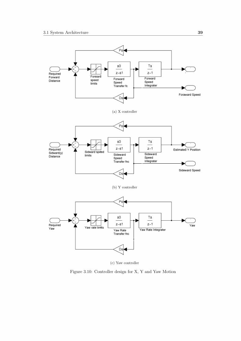
3.1 System Architecture 39
(a) X controller
(b) Y controller
(c) Yaw controller
Figure 3.10: Controller design for X, Y and Yaw Motion

3.2 Design Summary 40
3.2 Design Summary
Asynchronous data reader and writer have been used to avoid data loss. The datawriter reads the sensor data values such as magneto meter, altitude and GPS data.These data are stored on a data store. The data reader reads the data and sends itto the state estimator. State estimator estimates the position of quadcopter in basecoordinate space. The position controller has two components: altitude hold andsignal controller. Altitude hold controller has been designed to fly the quadcopter ina given altitude. The purpose of the signal controller is to achieve the target SNR.Keeping to that aim, it initially flies away from the base station. The flying distancewill be decided by the transfer function which uses a self-learning mechanism to decidethe distance that needs to be flown to achieve the given SNR. An algorithm has beenused to decide the direction of the flight by considering the SNR, and the local axisof the quadcopter. The distance and direction will be fed into the motion controllerwhich has 3 proportional derivative (PD) controllers in it: the X, Y axis controller andthe yaw controller. These controllers will calculate the error value as the di�erence tothe measured distance variable, with that it will converge to the desired point. Theoutput of the signal controller is a control signal of velocity of X, Y axis and angularspeed of local axis of the quadcopter. This is sent to the low level PID controller onthe drone. This will then control the flight.
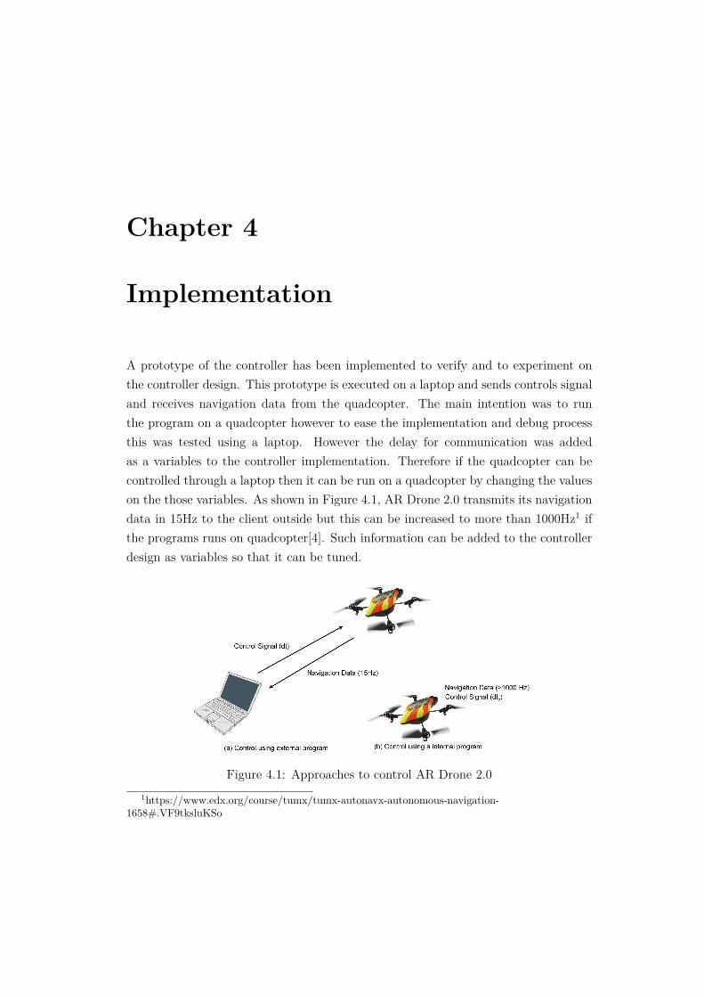
Chapter 4
Implementation
A prototype of the controller has been implemented to verify and to experiment onthe controller design. This prototype is executed on a laptop and sends controls signaland receives navigation data from the quadcopter. The main intention was to runthe program on a quadcopter however to ease the implementation and debug processthis was tested using a laptop. However the delay for communication was addedas a variables to the controller implementation. Therefore if the quadcopter can becontrolled through a laptop then it can be run on a quadcopter by changing the valueson the those variables. As shown in Figure 4.1, AR Drone 2.0 transmits its navigationdata in 15Hz to the client outside but this can be increased to more than 1000Hz1 ifthe programs runs on quadcopter[4]. Such information can be added to the controllerdesign as variables so that it can be tuned.
Figure 4.1: Approaches to control AR Drone 2.01https://www.edx.org/course/tumx/tumx-autonavx-autonomous-navigation-
1658#.VF9tksluKSo

4.1 Wi-Fi Network 42
4.1 Wi-Fi Network
Ad hoc mode is the default network mode on AR Drone 2.0. A user can connect theclient to the network by requesting a IP address from drone’s DHCP server and canleave whenever needed. In order to measure the SNR, the drone should be connectedto an existing network. Therefore to change the default settings of the drone, theinternal program on drone should be accessible. This can be accessed through telnet.By default AR Drone runs on the IP Address 192.168.1.1. Below is a shell commandthat can be used to access AR Drone 2.0 with root privileges.
1 Telnet 192.168.1.1
Following steps has to be followed to connect the AR Drone to another network:
1. Stop DHCP server
2. Stop ath0 interface
3. Bring back ath0 interface on ad hoc mode with the preferred essid
4. Run DHCP server to get an IP address
The above steps can be achieved through the below shell commands.
1 killall udhcpd2 ifconfig ath0 down3 iwconfig ath0 mode ad -hoc essid DEVICE_ESSID4 ifconfig ath0 192.168.1.1 netmask 255.255.255.0 up
4.2 SNR Reader
SNR can be computed by finding the signal and noise level of the communicationlink. These details can be directly fetched from the OS. However this feature onaccessing the signal level and noise level depends with the network card. On Atheroswireless driver implementation, it has been said that by using CMOS technology RSSIcannot be directly calculated rather absolute signal strength can be calculated[29].Absolute signal strength is the incoming signals relative to the noise floor. Atherosdriver implementation also suggests that absolute signal strength is the SNR. Howeverthe value for absolute signal strength is not discretized to a range. Therefore the valuefor noise floor is fixed and used as a relative value to calculate the SNR.

4.3 Controller Implementation 43
Values for RSS and noise floor can be fetched from the file /proc/net/wireless. Thisreturns the values for RSS and noise floor on unit Decibel-milliwatts(dBm). Figure4.2 shows a screen shot of the result.
Figure 4.2: Snapshot of the file read for calculating SNR
A simple server program has been created to fetch and serve the SNR values. Thisdata is then sent through a TCP socket to the client. The reason for using a TCP socketis because the controller requires the most recent data of SNR. This SNR data shouldbe stabled and continuous. Since TCP connection is reliable and ordered it guaranteesthat the received data is in the same order as its been sent. Whenever the controllerreceives a SNR it creates a control signal accordingly. However cognition controldecides the slot to send this signal to the quadcopter by considering the precision onthe di�erence between last and current result.
4.3 Controller Implementation
Node.js2 language has been used for the controller implementation. The reason forusing Node.js is because there are already basic tools and programs that has beenimplemented for AR Drone 2.0. These programs are well managed and stabled.
4.3.1 Data Reader and Writer
There are 3 main communication ports on AR Drone 2.0.
• Navigation data (navdata) is sent back to the controller though the UDP port5554.
• Video stream is sent through the UDP port 5555.
• Controlling and configuration of the drone is done using UDP port 5556
UDP port 5554 is used to initiate communication to get the navigation data . Thisprocess can be seen through the Figure 4.3. This figure describes the process ofaccepting the navdata_demo. navdata_demo is a data structure that holds altitude,
2http://nodejs.org/

4.3 Controller Implementation 44
rotation, speed...etc data. Similar configuration signal can be sent to the drone to getother sensor information.
Figure 4.3: Process for collecting navigation data[25]
The node.js library ’ar-drone’ is used to initiate the communication with the quad-copter. This is the node.js version of AR Drone SDK[24][25]. This SDK provides anAPI for handling the communication for data collection, controlling and configuration.Below is a code snippet for initiating the data collection. Furthermore AR Drone 2.0can be controlled through AT commands. Therefore whenever the high level con-troller generate a command it will be then converted to AT commands with the helpof ’ar-drone’ library.
1 var navdata_options = (2 navdata_option_mask ( arDroneConstants . options .DEMO)| # Navigation
Data3 navdata_option_mask ( arDroneConstants . options . MAGNETO )| # Magneto
meter4 navdata_option_mask ( arDroneConstants . options . ZIMMU_3000 )); #GPS
Data
The above code describes a navdata configuration. This is a request that is sent tothe quadcopter to get the demo, magneto, motion and GPS data back to the controller.The data collection and control is done concurrently. This can be easily achieved withnode.js since node.js supports asynchronous control flow. The below code describe theevent of reading the data from drone. Whenever client gets a data following functionwill be triggered with requested data as arguments.

4.3 Controller Implementation 45
1 ARclient .on(’navdata ’,function (data){2 #The data that needed can be extracted from here3 });
The above function will have the demo, magneto, wind and GPS data as arguments.Yet this won’t ensure that the client will always get the data it has requested. Thisis because for example, GPS has a delay and due to this, GPS frequency will be low.GPS frequency is small compared to the other navigation data[26]. Therefore theselatency has to be considered when designing a controller. This is one of the reason touse data fusion with GPS and dead reckoning for state prediction. A suitable errorhandling is needed to avoid the data loss. Through this setup asynchronous datareader and writer has been achieved. Figure 4.4 illustrates an abstract model of thedata reader and writer.
Figure 4.4: Schematic diagram of data reader and writer
4.3.2 State Estimator
State estimation is used to find the quadcopters position in a base coordinate system.GPS is one of the most widely used tool to estimate the position on an outdoor. Yetdue to GPS delay and noise this will lead to an inaccurate estimation. Thereforequadcopter motion sensor data is fused with GPS to increase the accuracy. For thispurpose EKF has been used. ’ardrone-autonomy’ is a node.js library that has beenused for the implementation of the state estimator. This is a library used for visualbased state estimation. This source is used as a base and made necessary changesto support GPS based prediction[27]. Following is a code snippet that shows motiondata being used for prediction step on EKF.
1 var pitch = data.demo. rotation .pitch . toRad ();2 roll = data.demo. rotation .roll. toRad ();

4.3 Controller Implementation 46
3 yaw = data.demo. rotation .yaw.toRad ();4 vx = data.demo. velocity .x / 1000;5 vy = data.demo. velocity .y / 1000;6 vz = data.demo. velocity .z / 1000;7 alt = data.demo. altitude ;8 dt = 1 / 15;
In the above code 15Hz is considered for dt because the drone sends navdata ina fixed rate[4]. The the above data is used for the prediction step on Kalman filter.Prediction step is illustrated on below code snippets.
1 var o = {dx: vx * dt , dy: vy * dt , dyaw: yaw - this. _last_yaw };2 this. _last_yaw = yaw;
Once the odometry is calculated then the changes is added to the state estimationas described on below code. In here predicted state is on the base coordinate system.
1 var state = this. _state ;2 state .x= state .x + o.dx*Math.cos( state.yaw)-o.dy*Math.sin(state.yaw
);3 state .y= state .y + o.dx*Math.sin( state.yaw)+o.dy*Math.cos(state.yaw
);4 state .yaw = state .yaw + o.dyaw;
Once the state is predicted the G and q term on the prediction step can becomputed. For this intent value for Q and R is in need. Q is same as the valueused on the ’ardrone-autonomy’ library[27]. This is because it has used the same deadreckoning approach for prediction and therefore it has the same covariance. This valuewas then validated by calculating the covariance using a test flight. An experimentwas done to find the measurement covariance noise(R) using GPS. For this intent GPSdata was gathered as depicted on Figure 4.5. This GPS data was gathered for 15 minand from this data the covariance was estimated as 2.2004.
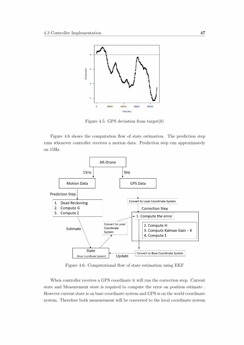
4.3 Controller Implementation 47
Figure 4.5: GPS deviation from target(0)
Figure 4.6 shows the computation flow of state estimation. The prediction stepruns whenever controller receives a motion data. Prediction step run approximatelyon 15Hz.
Figure 4.6: Computational flow of state estimation using EKF
When controller receives a GPS coordinate it will run the correction step. Currentstate and Measurement state is required to compute the error on position estimate .However current state is on base coordinate system and GPS is on the world coordinatesystem. Therefore both measurement will be converted to the local coordinate system

4.3 Controller Implementation 48
of the quadcopter. From which the error would be computed. Once the error iscomputed then it will update the current state. (Section A.0.1 and A.0.2 are examplesof code snippets to convert GPS coordinate to local coordinate system and code snippetfor correction step). Once the error is computed then correction parameters H and Kare calculated. After H and K are calculated then state will be updated. In here thecorrection is only done on position not on yaw value because the filtered value on yawvalue can directly be fetched from the drone.
4.3.3 PID Controller
Quadcopter steering commands is generated by a 4 DOF controller. Here 4 individualPD controllers have been used to control each degree of freedom. This includes X,Y,Zand Yaw. These controllers will steer the quadcopter from the base station by consid-ering the current state and the target distance. This target point will be provided bythe signal controller(Note: section 4.3.6 - signal controller). The controller generatescontrol commands considering the state on the base coordinate system of the drone.Code snippet on implementation of the PID controller is given below.
1 var time = Date.now ();2 # Compute dt to calculated integrate and derivative error3 var dt = (time - this. _last_time ) / 10004 var de = 0;5 if (this. _last_time != 0) {6 if (this. _last_error < Infinity ) {7 # Compute the derivative of the error8 de = (e - this. _last_error ) / dt;9 }
10 # Compute the integral error11 this. _error_sum += e * dt;12 }13 this. _last_time = time;14 this. _last_error = e;15 # Compute commands16 var command =this._kp*e+this._ki*this. _error_sum +this._kd*de;
Table 4.1 illustrates the parameter values used for the PID Controller. PID con-troller parameter values are determined considering the parameters used on ’ardrone-autonomy’ library [27]. These values are then verified by an experiment.

4.3 Controller Implementation 49
Axis P I DX 0.5 0 0.35Y 0.5 0 0.35Z 0.8 0 0.35
yaw 1 0 0.3
Table 4.1: Parameters for PID controller
In here PID controllers converge to the target by having maximum 0.1 precision.This means 10cm error on X,Y and Z and 5 degree error on yaw motion. Below is acode snippet to generate target distance to move.
1 this._go ({x:A, y:B, z:C, yaw: D});
When the above function is called. Then it will compute the distance to move onx,y,z axis and the direction to achieve. Coordinate A, B, C(arguments) and currentstate is used to compute the distance. This distance and angle to achieve will be setas the reference variable on the respective PD controllers.
4.3.4 Altitude Hold
Altitude hold can be achieved by setting up the desired target goal to the givenaltitude.
1 this._go ({x: state.x, y: state .y, z: altitude , yaw: state .yaw });
The altitude can be achieved by the command go(x:0,y:0,z=altitude). Howeveronce altitude is achieved then a continues error correction is needed. This need isillustrated in the Figure 4.7. Horizontal line on the figure illustrates the target altitude.
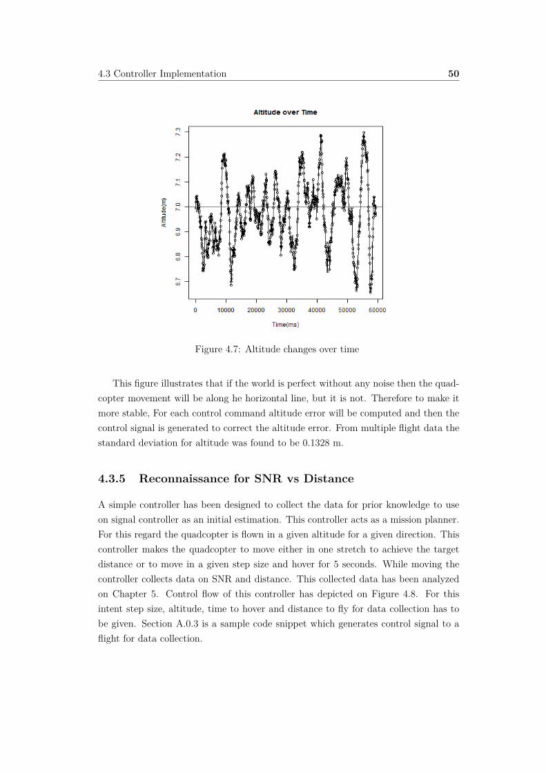
4.3 Controller Implementation 50
Figure 4.7: Altitude changes over time
This figure illustrates that if the world is perfect without any noise then the quad-copter movement will be along he horizontal line, but it is not. Therefore to make itmore stable, For each control command altitude error will be computed and then thecontrol signal is generated to correct the altitude error. From multiple flight data thestandard deviation for altitude was found to be 0.1328 m.
4.3.5 Reconnaissance for SNR vs Distance
A simple controller has been designed to collect the data for prior knowledge to useon signal controller as an initial estimation. This controller acts as a mission planner.For this regard the quadcopter is flown in a given altitude for a given direction. Thiscontroller makes the quadcopter to move either in one stretch to achieve the targetdistance or to move in a given step size and hover for 5 seconds. While moving thecontroller collects data on SNR and distance. This collected data has been analyzedon Chapter 5. Control flow of this controller has depicted on Figure 4.8. For thisintent step size, altitude, time to hover and distance to fly for data collection has tobe given. Section A.0.3 is a sample code snippet which generates control signal to aflight for data collection.

4.3 Controller Implementation 51
Figure 4.8: Flow diagram of the controller for reconnaissance
Figure 4.9 is a image which was taken from an experiment to collect data for initialestimation.
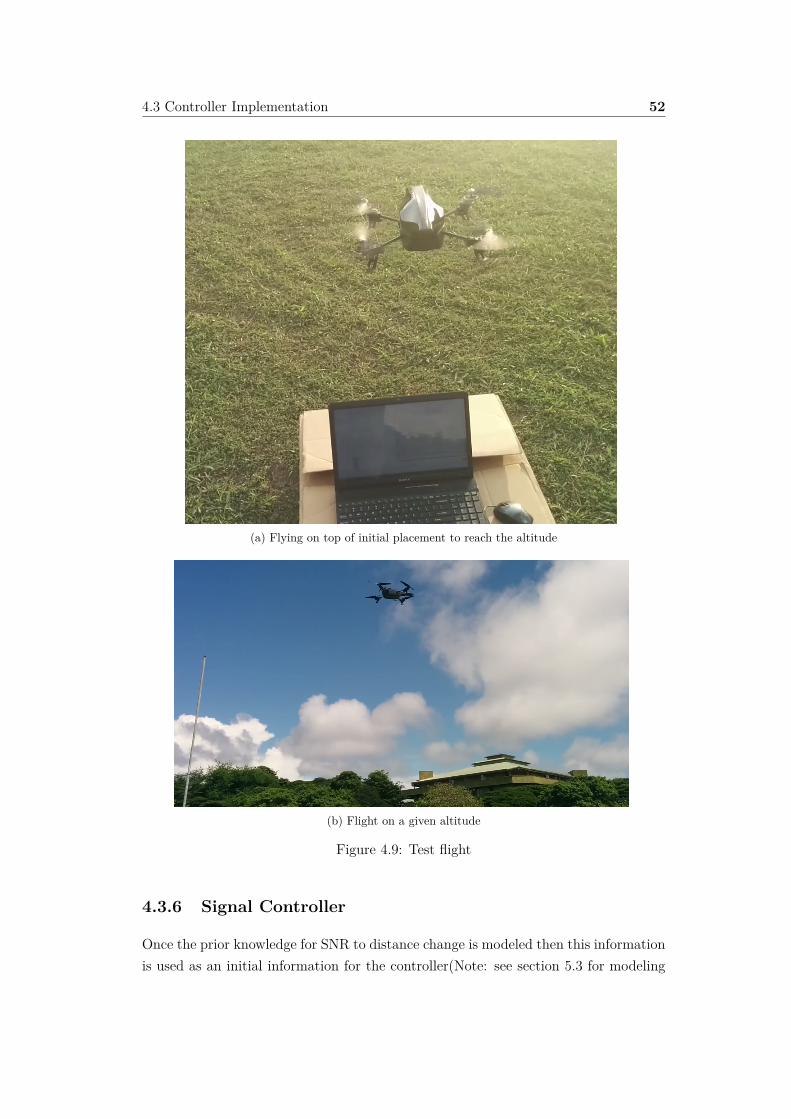
4.3 Controller Implementation 52
(a) Flying on top of initial placement to reach the altitude
(b) Flight on a given altitude
Figure 4.9: Test flight
4.3.6 Signal Controller
Once the prior knowledge for SNR to distance change is modeled then this informationis used as an initial information for the controller(Note: see section 5.3 for modeling

4.3 Controller Implementation 53
of initial estimation). This knowledge is stored on an array where its index is the SNRand the value is the distance from the base station.
SNRDM[Current SNR] will provide an approximate distance to achieve the currentSNR from base station. However the main purpose is to find the distance to the targetSNR from current SNR. This can be calculated by a linear approximation :
SNRDM[Target SNR]-SNRDM[Current SNR]=Distance to achieve.
The SNRDM will be used as a initial estimate to understand the distance change.However while flying the values on SNRDM will be updated with the recent valuesfor distance. This module will act as a online SNRDM. Figure 4.10 illustrates thedecision flow of the signal controller.
Figure 4.10: Decision flow of the SNR controller
Below is a sample code snippet that describes this algorithm.
1
2 if( global .SNR == global . ReferenceSNR ){3 #Hover4 ARctrl .go ({x: d.state.x,y:0,z: targetAltitude ,yaw: initialYaw });5 }else{6 # Checks if the controller has learned about the new
environemnt7 if( global . OnlineSNRDM [ global . ReferenceSNR ]==0){

4.3 Controller Implementation 54
8 distToMove = global .SNRDM[ global . ReferenceSNR ]- global . SNRDM[global .SNR ];
9 }else{10 # Compute the distance to be flown from knowledge that has
gained from online learning11 distToMove = global . OnlineSNRDM [ global . ReferenceSNR ]- global .
OnlineSNRDM [ global .SNR -1- MinSNR ];12 }13 global . nextTarget = curDistance + distToMove ;14 ARctrl .go ({x: global . nextTarget , y:0,z: targetAltitude , yaw:
initialYaw });15 }
The above code describes that while the quadcopter is flying, it continuously esti-mates where the target position is ought to be. The target position is then estimatedusing the current flight data and initial knowledge.

Chapter 5
Evaluation And Validation
This chapter focuses on a in depth analysis on reasoning and justification for selectedmodules. The evaluation and testing was focused on 5 stages.
1. Validation of state estimator
2. Evaluation of Data collection procedure.
3. Evaluation and validation of the knowledge module.
4. Modeling and Evaluation of Learning Algorithm.
5. Evaluation of Autonomous Controller for maintaining radio link quality.
Sony Vaio laptop was used as the base station for evaluation purposes. This has aAtheros AR9285 Wireless Network Adapter. For the intent of the experiments 2.4GHzmedium was used for the wireless communication.
5.1 State Estimator
State estimator provides an estimate of the current position. This is in need for thecontroller to verify the distance quadcopter had moved. Therefore an experiment hasbeen done to validate whether is it moving to the required distance.
To test the state estimator an experiment was done by providing the target distancefor the quadcopter. For this experiment three types of data collection procedure isused verify(Appendix B.0.4).
Once it achieved the target then distance was calculated by GPS, Kalman predic-tion and finally it was manually measured by a measuring tape. For testing purposesthree di�erent target distance was set. These distances were 5m, 10m and 14m. The

5.1 State Estimator 56
reason for using these values for the distance was because to keep the quadcopterwithin the range of the base station to avoid connection loss. We experiment with5 flights for each target distance. These flight were combined and the descriptiveanalysis of the actual, predicted and GPS can be seen on Table5.1.
Target Distance Type Mean Variance AbsoluteMeanError
(Estimate-
Measured)
AbsoluteMeanError
Variance(Estimate
-Measured)
5Predicted 5.232 0.04647 0.528 0.15277
GPS 6.06705 0.80831557 1.1421 0.28787557Physical Measurement 5.76 0.263 - -
10Predicted 10.138 0.01032 1.202 0.44212
GPS 12.34753559 3.128074112 1.00753558 1.34154559Physical Measurement 11.34 0.433 - -
14Predicted 14.156 0.00933 1.464 0.33263
GPS 16.83411379 3.234530079 1.47317201 0.83491588Physical Measurement 15.62 0.377 - -
Table 5.1: Mean and variance of the predicted distance, GPS calculation and physicalmeasurement
Above table depicts that prediction using Kalman filter and GPS has the sameerror. However this clearly illustrates that prediction has a small variance and smallabsolute mean error variance compared to the GPS. This shows that the Kalman fil-ter is more consistent than using the GPS measurement. However the absolute meanerror of GPS and Kalman prediction suggest that both has similar error. However forthe purpose of this controller design more consistent is needed than the absolute mea-surement. Because the controller predicts the distance to be moved from the currentposition and this distance will be continuously corrected. Therefore the quadcoptershould behave consistently throughout the flight. Furthermore in here consistency isvery much important because for the learning purpose deviation on the distance foreach SNR should be low. Therefore this shows that using Kalman filter fused withGPS is su�cient for the desired problem. However increasing the accuracy of theabsolute position will make this controller more stable.

5.2 Evaluation of Data Collection Procedure 57
5.2 Evaluation of Data Collection Procedure
In this section the focus is onto forming a data collection procedure to achieve con-trolled mobility with the quadcopter.Thus when experimenting on this, following ques-tion was arose when designing the yaw controller that is “If we move the quadcopterin a 2D space (fixed altitude) and if the quadcopter and base station uses omni di-rectional antenna then an argument can be made that moving the quadcopter to thedesired position is su�cient and there is no need of controlling the orientation”. Toanalyze this argument an experiment was done with the following hypothesis.
Hypothesis: Yaw Motion has no significance over the SNR on a fixed point ofspace.
In here only yaw motion is considered for the orientation because the quadcoptermoves on a 2D space (base coordinate system and fixed altitude).
Suitable approach to test this hypothesis would be making the quadcopter to flyand do the yaw motion in one fixed position. In theory this motion is possible howeverthere are other factors such as wind and motor motion errors that will make thequadcopter to drift away from its position. This would lead to inaccurate results forSNR readings due to change on distance. Therefore in order to do this experiment thequadcopter was placed on a rotatable disk base structure. This can be seen on Figure5.1. SNR over Yaw data was collected by rotating the base which the quadcopter wasplaced. After the data collection rotation data was compared with the data collectedfor without rotation.
Figure 5.1: Experiment on yaw over SNR
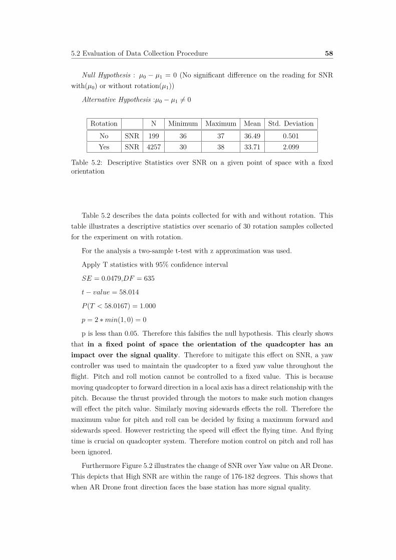
5.2 Evaluation of Data Collection Procedure 58
Null Hypothesis : µ0 ≠ µ1 = 0 (No significant di�erence on the reading for SNRwith(µ0) or without rotation(µ1))
Alternative Hypothesis :µ0 ≠ µ1 ”= 0
Rotation N Minimum Maximum Mean Std. DeviationNo SNR 199 36 37 36.49 0.501Yes SNR 4257 30 38 33.71 2.099
Table 5.2: Descriptive Statistics over SNR on a given point of space with a fixedorientation
Table 5.2 describes the data points collected for with and without rotation. Thistable illustrates a descriptive statistics over scenario of 30 rotation samples collectedfor the experiment on with rotation.
For the analysis a two-sample t-test with z approximation was used.
Apply T statistics with 95% confidence interval
SE = 0.0479,DF = 635
t ≠ value = 58.014
P (T < 58.0167) = 1.000
p = 2 ú min(1, 0) = 0
p is less than 0.05. Therefore this falsifies the null hypothesis. This clearly showsthat in a fixed point of space the orientation of the quadcopter has animpact over the signal quality. Therefore to mitigate this e�ect on SNR, a yawcontroller was used to maintain the quadcopter to a fixed yaw value throughout theflight. Pitch and roll motion cannot be controlled to a fixed value. This is becausemoving quadcopter to forward direction in a local axis has a direct relationship with thepitch. Because the thrust provided through the motors to make such motion changeswill e�ect the pitch value. Similarly moving sidewards e�ects the roll. Therefore themaximum value for pitch and roll can be decided by fixing a maximum forward andsidewards speed. However restricting the speed will e�ect the flying time. And flyingtime is crucial on quadcopter system. Therefore motion control on pitch and roll hasbeen ignored.
Furthermore Figure 5.2 illustrates the change of SNR over Yaw value on AR Drone.This depicts that High SNR are within the range of 176-182 degrees. This shows thatwhen AR Drone front direction faces the base station has more signal quality.

5.2 Evaluation of Data Collection Procedure 59
Figure 5.2: Graph on SNR changes with yaw on AR Drone 2.0
The next question on the data collection procedure was posed on whether movingor hovering a quadcopter in a same point of space makes a di�erent on SNR readings.This question arose because a quadcopter has a high node mobility and due to thatreadings of SNR might have unsteadiness compared to the hovering. Hovering tendsto be more stable in a fixed point of space. Therefore this arose following hypothesis :
Hypothesis : Data collection while moving and hovering in a same point of spacehas a significant di�erence on SNR reading.
To experiment this, a quadcopter was programmed to move autonomously with a1 meter step size with 5 seconds interval. This means that the quadcopter flies for 1m and hovers for 5seconds and then move another 1 m and likewise it moves to thetarget distance. We collected 360 sample points for each flying status (moving andhovering) from a single flight. Then this data was separately modeled and combinedinto one table with the columns : SNR, Flying Status and Yaw (Appendix B.0.5 -Flying status has two values 1 and 2. 1 indicates that the data collection was donewhile hovering and status 2 indicates that it was collected while moving. )
Null Hypothesis: Flying status has significant impact over the SNR.
Alternative Hypothesis : Flying Status has no significant impact over SNR.
Analysis : Using F-Test with 95 confidence interval.
To analyze this a univariate regression was conducted on SNR and flying status

5.3 Knowledge Module 60
with distance. Table 5.3 illustrates the significance of the attributes over the univariatemodel. In here it clearly shows that flying status is not significant to the model.Therefore flying status has no significant impact on the SNR reading.
Source Type III Sum of Squares Mean Square F Sig.Corrected Model 86.867 43.433 125.026 0
Intercept 208.243 208.243 599.442 0SNR 84.606 84.606 243.543 0
Flying Status 0.03 0.03 0.087 0.772
Table 5.3: Tests of Between-Attribute E�ects on Distance over SNR and Flying Status
The outcome of this analysis shows that node speed doesn’t e�ect the signalquality in a fixed point of space. This shows that SNR readings are reliable whenquadcopter moving or hovering.
From the outcome of the above two hypothesis a data collection procedure can beformed. This plan includes that the quadcopter should be flown in a fixed yaw valuerelative to the base station and collect SNR and distance data while either moving orhovering.
5.3 Knowledge Module
Knowledge module provides prior information to the cognitive system to make deci-sions. Therefore an analysis was done on how to model this knowledge. For this intent10 flight data was collected on a fixed position and was flown in a fixed direction asdepicted on the Figure 5.3. This figure illustrates the place where the experiments wasconducted and also it shows the direction the quadcopter was flown. The descriptionof the collected data has been illustrated on the Table 5.4.
No. of Flights Average Sample Points Per Data Set Target Distance For Flight10 218 14
Table 5.4: Description of the data collected for the knowledge module

5.3 Knowledge Module 61
Figure 5.3: Scenario used for the experiments
5.3.1 Pre Processing
These flight data were individually analyzed and was found that a pre processing is inneed. Figure 5.4 provides an illustration on how distance and SNR varies with timefor a flight. In this figure it is evident that the SNR readings have an unusual behaviorafter passing the target distance for the first time. Through observations it was foundthat this variation occurs due to the sudden change of velocity. This is because whenthe target distance is passed due to shoot out then PD controller suddenly providesa change on velocity to achieve the target. Thus due to sudden change on velocity,quadcopter does a quick reaction to achieve it. Because of this there will be a changeon orientation of the quadcopter and this will change position of the antenna. This isthe reason for having high fluctuation on SNR readings when current state is close tothe target distance. Therefore to avoid this the data was ignored on the point fromthe first pass of the target distance.
Still there are outliers on the filtered data. These outliers are generated due toeither continuous error correction done on altitude or by drifting. Due to this therewill be some small fluctuations on SNR readings. To avoid this a median is consideredfor each point of the data to reduce the e�ect of outliers.

5.3 Knowledge Module 62
Figure 5.4: A flight data set on SNR and distance variation over time
5.3.2 SNR vs Distance - Data Model
To model the knowledge module, the collected flight data set were combined togetherwith following attributes: {SNR, Distance, Flight_ID} (Appendix B.0.6). For mod-eling the distance change with SNR, the model was assumed as shown in Equation5.1.
Distance Ã3 1
SNR
4–
; – = 1 (5.1)
With this assumption an univariate regression was conducted on the data set. Table5.5 illustrates the result of this outcome. This results provides an acceptable value(78.6%) for R squared. Yet R squared does not indicate that model has a good fit.Therefore if we look into the residuals through Figure 5.5. This figure illustrates theresiduals of predicted distance. This depicts that there are randomness on residualshowever slight bias has formed and this can seen through from few clusters. Thereforethis indicates a somewhat of bias over coe�cients.
Figure 5.6 provides a normal P-P plot on residuals from which we can understandwhether the residuals are normalized or not. A good model will make the points tolie on the line(shown on the figure). However this figure shows shows that the resultlies closer to the line and in some point there are few deviation. However if we look

5.3 Knowledge Module 63
into Figure 5.7, It shows that observed and prediction forms a closer line and it hassome deviations.
R squared 78.6%Adjusted R squared 78.4%
Intercept -17.618Coe�cient 788.054
Table 5.5: Results from univariate regression (SNR, distance) when – = 1
Figure 5.5: Residual plots over observation on univariate regression ( SNR, distance )when – = 1
Figure 5.6: Normal P-P Plot on standardized residual for distance on univariate re-gression ( SNR, distance ) when – = 1

5.3 Knowledge Module 64
Figure 5.7: Prediction over observation on Uni variate Regression ( SNR, Distance ),when – = 1
Further analysis was done to test whether increasing or decreasing the – on Equa-tion 5.1 does make a di�erence. The outcome of this has been illustrated on Table 5.6.When – increases the value for R squared decreases. And also when looking at thecoe�cient it is clearly evident that with increase of – the coe�cient has increased andthe weight for 1/SNR has decreased. Therefore this shows that increasing – makesthe model more complex compared to the improvement it does. When decreasing the– it doesn’t make much di�erence on residuals. Therefore to make this model simplewe can conclude – = 1. This gives us a simple model for the estimation.
– R squared Highest Degree Coe�cient (1/SNR) Intercept0.33 78.7% 233.323 -67.1340.5 78.7% 278.222 -42.0231 78.6% 788.054 -17.6182 77.4% 12340.402 -5.3443 75% 249524.745 -1.190
Table 5.6: Result from regression over SNR and distance while changing –
5.3.2.1 SNR and Flight ID vs Distance - Data Model
To further understand the bias on the knowledge module Flight_ID was added tothe data model to the regression model. This is to understand whether the modeldepends on di�erent environment conditions over the same environment with di�er-ent flights. Table 5.7 clearly illustrates that Flight ID is significant over the model.

5.3 Knowledge Module 65
Therefore this has increased the value on R squared. In Figure 5.8 it clearly indicatesmore randomness on residuals compared to model which had the attribute -{SNR,Distance}.
This model has outperformed the prediction compared to the model on Table 5.5.Figure 5.8 depicts that the residuals is more random and the Figure 5.9 illustratesthat standardized residuals of the distance is more normalized. Further Figure 5.10 isevident that the prediction and observation is following a closer line. Therefore thisis clearly shows that the Flight Id is significant.
R squared 88.8%Adjusted R squared 87%
Parameter Significance F-TestIntercept 0.000
Co�. 1/SNR 0.000Flight_Id 0.000
Flight_Id Period_ID Significance T testFlight_Id(1) 1 0.000Flight_Id(2) 1 0.332Flight_Id(3) 1 0.447Flight_Id(4) 2 0.056Flight_Id(5) 2 0.002Flight_Id(6) 2 0.337Flight_Id(7) 2 0.001Flight_Id(8) 3 0.116Flight_Id(9) 3 0.002Flight_Id(10) 3 Base
Table 5.7: Results from univariate regression model (SNR, Distance, Flight ID) when– = 1
When looking at the Period ID(Di�erent time slots) with flight ID on Table 5.7.It suggest that there are flights that has the similar characteristics on di�erent period(eg: flight ID-2, 3, 6, 10). This shows that a model can be used with another flighthowever choosing which flight it is will di�cult.

5.3 Knowledge Module 66
Figure 5.8: Residual plots over observation on Uni variate Regression (SNR, Distance,Flight ID), when – = 1
Figure 5.9: Normal P-Plot on standardized residual for distance on univariate regres-sion model (SNR, Distance, Flight ID) when – = 1

5.3 Knowledge Module 67
Figure 5.10: Predicted and observed distance on univariate regression model(SNR,Distance, Flight ID) when – = 1
Outcome of this analysis clearly shows that one model cannot be used fordi�erent flight. Yet even without the flights characteristics still the model is accept-able for initial estimation. Moreover this conclusion also suggest that for each flightthe communication range di�ers therefore we cannot always achieve the maximumdistance with a fixed distance based approach.
5.3.2.2 Summary
The above analysis is evident for using cognitive control system as the basis principleof the controller. Because the outcome of the experiments illustrates unlike to a fixeddistance based approach, SNR to distance model has a need for a controller thatreacts to the change on the environment. Therefore for each flight a SNR to distancebased model is in need. This is infeasible to adapt therefore learning based model wassuggested. However we can have an acceptable approximation on SNR vs distancemodel as for the knowledge for the initial estimation. Furthermore increasing the – onEquation 5.1 suggest that the model becomes more complex compared to improvementit does and decreasing the – doesn’t makes a di�erence. Therefore knowledge modulecan illustrated through an approximate module :
Distance = M ú3 1
SNR
4+ C
From experiments the values for M and C was concluded as 788.054 and -17.618 forthe place depicted on Figure 5.3. Having multiple test on the environment will lead to

5.4 Learning Module 68
more accurate initial estimation. However its is proven that the controller cannot relyon this data throughout the flight. Therefore a suitable learning module is in need.This will be used to update the initial estimation while flying.
5.4 Learning Module
The main intent of the learning module is to predict the target distance for the refer-ence SNR while flying. To achieve this we have to solve the problem on SNR outliers.These outliers occurs due to the sudden change on orientation, drifting and whencorrecting the altitude error. A median filter was used to avoid this on knowledgemodule. However median filter cannot be used as an online learning algorithm due toits complexity and growing space. Therefore for the learning purpose harmonic mean(Equation 5.2) was used on distance data for a given SNR. “Harmonic mean tends tomitigate the impact of large outliers and aggravate the impact of small ones”[30].
H = n1
x1+ 1
x2+ 1
x3+ .... + 1
xn
(5.2)
An analysis was done to validate whether the outcome of the median and the harmonicmean on the flight distance for a SNR is same or significantly di�erent. To test thisharmonic mean was applied on the 10 flight data which was collected for the knowledgemodeling. (Note: The outcome of this can be seen on Appendix B.0.7)
Hypothesis : median (µ0) and harmonic mean(µ1 )over the collected flight dataset is not significant
Null Hypothesis : µ0 ≠ µ1 = 0
Alternative Hypothesis :µ0 ≠ µ1 ”= 0
A two sample t-test with two tailed was conducted on Table 5.8.
Filter mean std dev nMedian 6.6831 4.347882898 121
Harmonic Mean 6.5686 4.349421178 121
Table 5.8: Mean and standard deviation of the filtered data (median and harmonicmean)
Apply T statistics with 95% confidence interval with Z approximation :
SE = 0.5591,DF = 239.5
t ≠ difference = 0.205

5.5 Evaluation of Autonomous Quadcopter Controller for maintaining Radio LinkQuality. 69
p = 2 ú min(0.581, 0.419) = 0.838
p is greater than 0.05. This shows that the di�erence is not significant. Thereforeharmonic mean can be used as a filter instead of median filter for the learning purpose.Therefore for the online learning purpose Equation 5.2 can be updated as followingequations 5.3 & 5.4 as an learning algorithm.
HSNR,t = nSNR,t≠1 + 1nSNR≠1
HSNR,t≠1+ 1
dSNR,t
(5.3)
nSNR = nSNR,t≠1 + 1 (5.4)
The above model is still vulnerable to sudden change of orientation. Where thischange can impact the SNR reading. Therefore to minimize this e�ect a filter wasused. This has been described using the ternary operator on equation 5.5:
((SNRt≠1 + CSNR) < SNRt) ? Accept SNRt : Reject SNRt (5.5)
CSNR indicates the Ceiling on the standard deviation of the SNR. From the 10flight data the standard deviation was found as 1.326241135 . Therefore CSNR is 2.CSNR describes the maximum SNR change that could occur from the current SNRreading. This will minimize the the sudden fluctuation on SNR readings. The use ofCSNR has been justified on Section 5.5.1.
5.5 Evaluation of Autonomous Quadcopter Con-troller for maintaining Radio Link Quality.
Performance of the controller has been analyzed on this section. As depicted on Table5.9, 22 flight data was collected for the evaluation. These flights were performed ondi�erent day and time. All these flight were flown in the altitude of 7 meters. Theseflight were experimented with the target SNR 25dB and 30dB. These two SNR valueswere picked because through experiments it had been shown that 40dB-25dB is therange for a good link quality1. Therefore we picked the minimum SNR and anothervalue in that range for experiments.
Target SNR With Prior Knowledge Without Prior Knowledge30 5 525 7 5
Table 5.9: Number of Flights with di�erent conditions1http://www.enterprisenetworkingplanet.com/netsp/article.php/3747656/WiFi-Define-
Minimum-SNR-Values-for-Signal-Coverage.htm

5.5 Evaluation of Autonomous Quadcopter Controller for maintaining Radio LinkQuality. 70
In the experiments all flights achieved its target SNR. The detailed summary ofthese flights can be seen on the Table 5.10. Step size 0.5m was used for flights whichdid not have a prior knowledge.
In the Table 5.10 ’Time’ means the time taken for the flight to achieve the targetSNR and been stabled on that point for more than 5 seconds.
Flight ID Target SNR Prior Knowledge Step Size Time Distance1 30 No 0.5 43.974 5.482291432 30 No 0.5 6.367 3.7807219523 30 No 0.5 86.548 4.01564 30 No 0.5 11.574 7.12655 30 No 0.5 27.598 8.15646 30 Yes - 56.81 5.084152667 30 Yes - 4.948 5.3077497388 30 Yes - 13.564 4.8244542539 30 Yes - 25.518 8.59460561610 30 Yes - 37.154 7.58264307911 25 No 0.5 60.283 15.6146348812 25 No 0.5 72.446 19.8185406613 25 No 0.5 84.141 20.484695114 25 No 0.5 56.336 12.3006840515 25 No 0.5 121.292 24.5712725416 25 Yes - 57.473 15.6214290917 25 Yes - 31.469 14.6134292118 25 Yes - 32.815 14.6134292119 25 Yes - 37.136 19.8691610720 25 Yes - 23.552 32.3137370221 25 Yes - 41.673 19.037822 25 Yes - 60.921 15.0500971
Table 5.10: Time taken to achieve the target SNR and the flown distance
Furthermore the descriptive statistics of the Table 5.10 is illustrated on the Table5.11.

5.5 Evaluation of Autonomous Quadcopter Controller for maintaining Radio LinkQuality. 71
Target SNR PriorKnowledge
Parameter N Minimum Maximum Mean Std.Deviation
25No
Time 5 56.336 121.292 78.8996 26.0860Distance 5 12.300 24.5712 18.5579 4.72435
YesTime 7 23.552 60.9021 40.71985 13.81609
Distance 7 14.61 32.31373 18.73129 6.364059
30No
Time 5 6.367 86.548 35.2122 32.25259Distance 5 3.7807 8.1564 5.71230 1.912869
YesTime 5 4.948 56.81 27.5988 20.36516
Distance 5 4.8244 8.5946 6.27872 1.699132
Table 5.11: Descriptive statistics of the flights
A further analysis was done on below section to understand how controller behaveswith and without a prior knowledge.
5.5.1 SNR Controller with Prior Knowledge
12 Flights were flown with the prior knowledge. And all the flights have achievedthe target SNR. A further analysis was done on a single flight to understand thecontroller behavior. The controller was designed to move through the X axis on thebase coordinate system while maintaining a fixed value on Y, Z axis and Yaw. Thebehavior on Y, Z axis and Yaw Orientation is depicted on the Figure 5.11. This figureillustrates the behavior of the quadcopter and the controller. In this the ’StateA’indicates the current position on axis A. ’GoalA’ indicates the target to achieve onaxis A and ’ControlUA’ indicates the current velocity of the quadcopter on axis A.As the Figure 5.11 depicts Y,Z and yaw controller had a 0,7,0 respectively
When quadcopter takes o� the controller gives the priority to the Z axis con-troller(Altitude Hold). Z axis controller sends a control signal continuously to thequadcopter’s low level controller to achieve the target altitude. This in regards makesthe quadcopter to provide initially a larger thrust to achieve a high value on velocitywhich will then reduce when its closer to the target altitude. Once it reaches thetarget altitude then it gives priority to the X axis controller however z axis controllerwill continuously corrects its error while flying (See Figure 5.11b). Similar to this, Yaxis controller continuously makes the quadcopter to fly parallel to the X axis throughthe zero point (see Figure 5.11a). In both the Figure 5.11b & 5.11a there is a sud-den fluctuation around 118719 ms. Through the observation, it was found that thisarouse due to the influence of the wind on the quadcopter. This wind tries to push thequadcopter away from achieving the target. To mitigate this drift controller creates a

5.5 Evaluation of Autonomous Quadcopter Controller for maintaining Radio LinkQuality. 72
larger thrust to achieve the target. Furthermore the Table 5.12 provides a clear picturethat Y axis mean is very close to zero and standard deviation is also a small value(40 cm). Z axis also is close to the target value 7 meters and the standard deviationis 12 cm. Therefore this gives a reasonable conclusion that the quadcopter has triedto maintain its trajectory. However For the Yaw Controller it has a mean of -0.1167radian (-6.68687584 degree) and has standard deviation of 0.4933975 (28.2695944 de-gree). This shows that yaw motion has a struggle to maintain its orientation. Yawmotion is relatively very slow compared to other movements. Therefore it takes timeto regain its orientation.
(a) Changes on Y axis (b) Changes on Z axis
(c) Changes on Yaw
Figure 5.11: Current state, target and quadcopter speed with the Time

5.5 Evaluation of Autonomous Quadcopter Controller for maintaining Radio LinkQuality. 73
N Minimum Maximum Mean Std. DeviationY Axis 2393 -2.605 1.532 -0.05449 0.452371Z Axis 2393 6.460 7.427 7.00202 0.122589Yaw 2393 -3.9926 21.2946 -0.116708 0.4933975
Table 5.12: Descriptive Statistics over the changes on distance over the Y, Z Axis andYaw
Furthermore a statistical analysis was done to a flight to test whether Y, Z con-trollers are achieving its target or not. Following hypothesis tests are done to validatethe statements on Y and Z axis :
Hypothesis : Y Controller achieves its target therefore there is no significantdi�erence between the real target and the achieved target.
Null Hypothesis (target goal and current state has no significance): µ0 ≠ µ1 = 0
Alternative Hypothesis :µ0 ≠ µ1 ”= 0
One sample t-test (z approximation) was conducted over the data on Table 5.13.
Y Axis n Mean Std. DeviationState 2393 -0.05449 0.452371
Target (Population) 0
Table 5.13: Two mean descriptive for state and target for Y Axis
Apply T statistics with 95% confidence interval :
SE = 0.0092,
z ≠ difference = 5.892
p = 2 ú min(1, 0) = 0
p is less than 0.05. This shows that the di�erence is significant. Therefore thisclearly illustrates that Y axis controller is not achieving the actual target. HoweverTable 5.12 illustrates it is very close to the target value.
Furthermore a similar analysis was done on Z axis :
Hypothesis : Z Controller achieves its target therefore there is no significantdi�erence between the real target and achieved target.
Null Hypothesis (Goal and State has no significance): µ0 ≠ µ1 = 0
Alternative Hypothesis :µ0 ≠ µ1 ”= 0
One sample t-test (z approximation) was conducted over the data on Table5.14.

5.5 Evaluation of Autonomous Quadcopter Controller for maintaining Radio LinkQuality. 74
Z Axis n Mean Std. DeviationState 2393 7.00202 0.122589
Target (Population) 7
Table 5.14: Two mean descriptive for state and target for Z Axis
Apply T statistics with 95% confidence interval :
SE = 0.0025
z ≠ difference = ≠0.806
p = 2 ú min(0.7899, 0.21013) = 0.4202
p is larger than 0.05. Therefore this shows that the di�erence is not significant.Therefore this clearly illustrates that Z axis controller is achieving the target goal.
In the above two hypothesis, we can see that Y is not achieving the target but Z isachieving it. However Y is very close to the target value. From this we can concludethat in a deterministic model a given target can be achieved but in practical thereare factors such as motor errors, timing, environmental influences etc. These factorswill continuously influence the quadcopter to drift. However Table 5.12 suggests thatY and Z axis controllers and yaw controller achieves the target when looking at themean and the standard deviation. Furthermore the standard deviation on yaw is muchhigher compared to the other two axis. Therefore this could create outliers on SNRreading.
An analysis was conducted to understand cognition behavior of on the controller.This case it is used to control the mobility on the X Axis on base coordinate. Thebehavior of the X axis controller is illustrated on the Figure 5.12. Figure 5.12a illus-trates that initially it takes time to initiate where in this case the priority has given toZ axis controller to achieve the altitude. Once Z axis controller achieves the altitudethen X axis controller uses prior knowledge, from which it has a reasonable conclusionof where the target might be. This information is then then used to take a largervalue for initial thrust. When X axis controller converges to the goal then it maintainsquadcopter’s velocity to a smaller value to avoid the shoot out. Still on the figure thefluctuation around 118719 ms can be seen. This is the e�ect of the wind. Even whenthere are influences on quad copter, controller still tries to with stand and achieve thetarget by increasing the velocity. Figure 5.12b illustrates the decision made by thecontroller (GoalX) with regards to the change of SNR over time.

5.5 Evaluation of Autonomous Quadcopter Controller for maintaining Radio LinkQuality. 75
(a) Current state, target and generated control signal changes withthe time on X axis
(b) State and target Changes with the SNR on X axis
Figure 5.12: Behavioral of the cognitive controller with prior knowledge
A further analysis was done to understand the behavior of the controller when itscloser to the target SNR. This has been illustrated on the table 5.15. An inference canbe made from this table that having a SNR as reference had a deviation 1.3 metersand a deviation 3.882 dB on SNR.

5.5 Evaluation of Autonomous Quadcopter Controller for maintaining Radio LinkQuality. 76
N Minimum Maximum Mean Std. DeviationState Distance 2187 15.381 21.999 18.90846 1.438984Goal Distance 2187 15.591 22.259 19.03114 1.309722
SNR 2187 15 33 23.89 3.882
Table 5.15: Descriptive Statistics over the changes on distance over the X Axis andSNR after the first pass of the target SNR 25dB (with prior knowledge)
A statistical test is done to check whether there is any significant di�erence betweenthe real target and achieved SNR value on a single flight :
Hypothesis : X axis controller achieves the target SNR therefore there is nosignificant di�erence between the real target and achieved value.
Null Hypothesis (target and achieved SNR has no significance): µ0 ≠ µ1 = 0
Alternative Hypothesis :µ0 ≠ µ1 ”= 0
One sample t-test (z approximation) was conducted over the data on Table5.16 .
X Axis n Mean Std. DeviationSNR 2187 23.89 3.882
Target(Population) 25
Table 5.16: Two mean descriptive for SNR and target SNR
Apply T statistics with 95% confidence interval :
SE = 0.083
z ≠ difference = 13.37
p = 2 ú min(0, 1) = 0
p is less than 0.05. This shows that the di�erence is significant. Therefore thisillustrates that controller doesn’t achieve it’s real target. Reasons for such deviationis due to the outliers on SNR reading.
Therefore to mitigate this problem, we had proposed an outlier filter CSNR. Thebehavior of the controller with the filter CSNR is depicted on Figure 5.13.

5.5 Evaluation of Autonomous Quadcopter Controller for maintaining Radio LinkQuality. 77
Figure 5.13: SNR and status changes with Time
Figure 5.12 and 5.13 was obtained to the same flight. However we have shownthat without CSNR filter (raw data) it doesn’t achieve the target. Therefore a furtherevaluation was conducted to test whether flight with CSNR filter achieves the targetSNR. Figure 5.13 clearly illustrates that noise filter on SNR makes the flight moresmoother. The descriptive statistics of the smoothed SNR change is depicted onTable5.17.
N Minimum Maximum Mean Std. DeviationSmoothed SNR 1038 16 44 25.12 2.826
Table 5.17: Descriptive statistics of the smoothed SNR
Hypothesis : X Controller achieves its target SNR. therefore there is no significantdi�erence between the target and achieved SNR after smoothing.
Null Hypothesis (goal and achieved SNR has no significance): µ0 ≠ µ1 = 0
Alternative Hypothesis :µ0 ≠ µ1 ”= 0
One sample t-test (z approximation) was conducted over the data on Table 5.17 .
Apply T statistics with 95% confidence interval :
SE = 0.0854
z ≠ difference = ≠1.406
p = 2 ú min(0.07995, 0.9201) = 0.1598
p is greater than 0.05. This shows that the di�erence is not significant. Therefore

5.5 Evaluation of Autonomous Quadcopter Controller for maintaining Radio LinkQuality. 78
this illustrates that module achieves its the target SNR. Therefore from this we canconclude that without the outlier filter we cannot achieve the target. This justifiesthe reason for using CSNR as a filter to remove the noise on SNR data. This onlymeans that the quadcopter continuously achieving its target SNR after smoothing.We further analyzed the percentage of hovering compared to the total flight time. Forthis intent we proposed a metric ’Hover Measure’ :
Hover Measure = Total hovering time from the first reach of target SNR
Total flying time from the first reach of target SNRx100 %(5.6)
The Equation 5.6 is only applicable after the first reach of target SNR. The aboveflight was analyzed with the hover measure and it indicated 24.88% . This clearlyindicates that even though the mean of smoothed SNR suggest it achieves the targetSNR however hover measure indicates that it has only flown 28.42% of total time.Therefore this indicates that the flight is continuously moving back and forth and thiscan be seen on Figure 5.14 .
Figure 5.14: Distance variation on X axis after the first reach of the target SNR
On the above experiments we have used two metrics to measure the performance.
1. Mean of smoothed SNR
2. Hover Measure
mean of smoothed SNR indicates whether the target is achieved or not and hovermeasure indicates the percentage of the hovering with the target SNR over total flight

5.5 Evaluation of Autonomous Quadcopter Controller for maintaining Radio LinkQuality. 79
time. Further analysis was done to test the hover on all the flights and the results isdepicted on Table 5.18.
Flight ID Hover Measure HoverMeasure -
Mean
HoverMeasure -
StdDeviation
TargetSNR
Mean ofSmoothed
SNR
Std. Deviation
6 26.28%
30.16 0.131819
30 29.54839 5.34057 27.87% 30 30 0.4803848 17.832% 30 31.3125 3.1020749 52.67% 30 30.3125 3.102010 26.1507% 30 30.32 0.63820716 6.5%
13.63 0.075838
25 26.16667 2.69522317 20.6% 25 24.95413 0.85418 24.88% 25 24.92157 0.52318819 7.8% 25 23.8 2.3360520 6.2% 25 25.38938 1.769921 18.42% 25 25.04968 1.02594122 10.99% 25 24.73555 2.826023
Table 5.18: Hover measure and descriptive of smoothed SNR over the flights withprior knowledge
Table 5.18 illustrates that when considering mean and the standard deviation ofthe smoothed SNR, this suggests that the controller is achieved its very close to thetarget SNR . However when considering the hover measure, this has a very small value.This is because even though the quadcopter is very close to the target SNR it is stillmoving back and forth. The reason for such movement is that when SNR is decreasing,rate of change on distance for a SNR is increasing. This is depicted on Figure 5.15.This figure shows that when we move the quadcopter to a smaller SNR value thenhover time will decrease. Because it only has a small distance range to move. Thiscan be tested with following hypothesis.
Hypothesis :
Null Hypothesis : Hover Measure for SNR 30dB is greater than the 25dB: µ0 > µ1
Alternative Hypothesis :µ0 <= µ1
A two-sample one tail t-test is done over the data on Table 5.18.
Apply T statistics with 95% confidence interval :
DF = 5.894
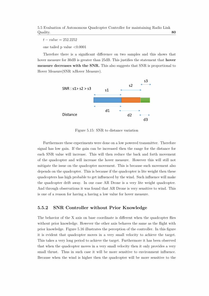
5.5 Evaluation of Autonomous Quadcopter Controller for maintaining Radio LinkQuality. 80
t ≠ value = 252.2252
one tailed p value <0.0001
Therefore there is a significant di�erence on two samples and this shows thathover measure for 30dB is greater than 25dB. This justifies the statement that hovermeasure decreases with the SNR. This also suggests that SNR is proportional toHover Measure(SNR ÃHover Measure).
Figure 5.15: SNR to distance variation
Furthermore these experiments were done on a low powered transmitter. Thereforesignal has low gain. If the gain can be increased then the range for the distance foreach SNR value will increase. This will then reduce the back and forth movementof the quadcopter and will increase the hover measure. However this will still notmitigate the issue on the quadcopter movement. This is because such movement alsodepends on the quadcopter. This is because if the quadcopter is lite weight then thesequadcopters has high probable to get influenced by the wind. Such influence will makethe quadcopter drift away. In our case AR Drone is a very lite weight quadcopter.And through observations it was found that AR Drone is very sensitive to wind. Thisis one of a reason for having a having a low value for hover measure.
5.5.2 SNR Controller without Prior Knowledge
The behavior of the X axis on base coordinate is di�erent when the quadcopter flieswithout prior knowledge. However the other axis behaves the same as the flight withprior knowledge. Figure 5.16 illustrates the perception of the controller. In this figureit is evident that quadcopter moves in a very small velocity to achieve the target.This takes a very long period to achieve the target. Furthermore it has been observedthat when the quadcopter moves in a very small velocity then it only provides a verysmall thrust. Thus in such case it will be more sensitive to environment influence.Because when the wind is higher then the quadcopter will be more sensitive to the

5.5 Evaluation of Autonomous Quadcopter Controller for maintaining Radio LinkQuality. 81
wind. However in the case of the flight with the prior knowledge it moves with a largerthrust so that the e�ect of wind is minimized. Figure 5.17 illustrates the decisionsand behavior of the controller on a flight. After 19714 ms the controller gets activatedand then it takes 0.5 m as a step size to converge the target.
Figure 5.16: Behavioral of the cognitive controller without prior knowledge
Figure 5.17: Smoothed SNR and status changes with Time
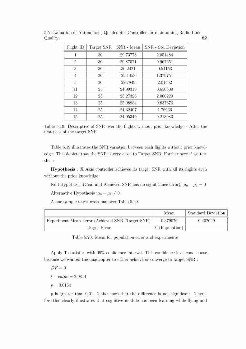
5.5 Evaluation of Autonomous Quadcopter Controller for maintaining Radio LinkQuality. 82
Flight ID Target SNR SNR - Mean SNR - Std Deviation1 30 29.73778 2.0514842 30 29.87571 0.9676513 30 30.2421 0.541534 30 29.1453 1.3797515 30 28.7849 2.0145211 25 24.99319 0.65050912 25 25.27326 2.00022913 25 25.08984 0.83767614 25 24.32407 1.7696615 25 24.95349 0.213083
Table 5.19: Descriptive of SNR over the flights without prior knowledge - After thefirst pass of the target SNR
Table 5.19 illustrates the SNR variation between each flights without prior knowl-edge. This depicts that the SNR is very close to Target SNR. Furthermore if we testthis :
Hypothesis : X Axis controller achieves its target SNR with all its flights evenwithout the prior knowledge.
Null Hypothesis (Goal and Achieved SNR has no significance error): µ0 ≠ µ1 = 0
Alternative Hypothesis :µ0 ≠ µ1 ”= 0
A one-sample t-test was done over Table 5.20.
Mean Standard DeviationExperiment Mean Error (Achieved SNR- Target SNR) 0.379076 0.402029
Target Error 0 (Population)
Table 5.20: Mean for population error and experiments
Apply T statistics with 99% confidence interval. This confidence level was choosebecause we wanted the quadcopter to either achieve or converge to target SNR :
DF = 9
t ≠ value = 2.9814
p = 0.0154
p is greater than 0.01. This shows that the di�erence is not significant. There-fore this clearly illustrates that cognitive module has been learning while flying and

5.5 Evaluation of Autonomous Quadcopter Controller for maintaining Radio LinkQuality. 83
achieving the target goal without prior knowledge. This proves that the proposedcontroller achieves the target SNR with or without the prior knowledge.
5.5.3 SNR Controller with Prior Knowledge vs without PriorKnowledge
It has been proven that the target SNR can be achieved with or without prior knowl-edge. A further analysis was done on time taken for achieving target SNR for thecontrollers with or without prior knowledge. It shows that using prior knowledgemakes the convergence faster. However a question arouse whether is there a signifi-cant di�erence. In order to test this following hypothesis was claimed :
Hypothesis: Time taken for achieving SNR 25 with or without prior knowledgeis not significant
Null Hypothesis : µ0 ≠ µ1 = 0
Alternative Hypothesis :µ0 ≠ µ1 ”= 0
A two-sample t-test was conducted on SNR 25dB on table 5.11.
Applied T statistics with 95% confidence interval :
DF = 5.61
t ≠ value = 2.987
p = 2 ú min(0.98928, 0.0107) = 0.0265
p is less than 0.05 therefore this falsifies the null hypothesis. This clearly showsusing prior knowledge makes the quadcopter to achieve the target faster compared toflight without prior knowledge. However flight without prior knowledge needs a stepsize. Depending on the step size the convergence time can vary.
Further analysis was done to test whether the flight with prior knowledge andwithout prior knowledge has the same learning.
Hypothesis :
To test this claim an argument can be made that the flight should have the samedistance for the SNR after the end of the flight.
A two-sample t-test on on combined data set of SNR 25dB and 30dB was done andthis has been depicted on table 5.11. For this intent T statistics with 95% confidenceinterval was applied

5.5 Evaluation of Autonomous Quadcopter Controller for maintaining Radio LinkQuality. 84
Sample With PriorKnowledge
Sample WithoutPrior Knowledge
2 sample 2tailed T Test
with 95 %Confidence
TargetSNR
n Mean Std.Deviation
n Mean Std.Deviation
DF t- value P (twosided)
25 7 18.7313 6.36406 5 18.558 4.72435 9.4 0.054 0.957830 5 6.278721 1.699132 5 5.712303 1.912869 7.8903 0.495 0.6341
Table 5.21: Two sample mean test on distance for SNR 25 dB and 30dB
Table 5.21 illustrates that the flights with and without prior knowledge has nosignificant di�erence on achieved distance. This shows that both had achieved thesame learning. However with prior this learning has become faster.
5.5.4 Analysis of Cognitive model decision with the changeof Transmitter Power
A further analysis was conducted to test whether the quadcopter achieves its targetSNR even if there is a sudden change on the characteristics of the signal. Thereforeto test this a simple program was created to control the wireless transmitter power ofthe access point. This program has been depicted on Figure 5.18.
Figure 5.18: Access point controller to change transmitter power
This program was used change the transmitter power while the quadcopter is flying.For the purpose of this experiment a timer was set to change the transmitter powerfrom 14 to 12 and 12 to 10. Each level will last for 120 seconds. With these changesthe flight data was analyzed to understand the behavior of the flight decision . Thisis depicted on Figure 5.19.

5.5 Evaluation of Autonomous Quadcopter Controller for maintaining Radio LinkQuality. 85
Figure 5.19: Quadcopter behavior and perception on SNR with TX Power
Table 5.22 illustrates the statistics of the SNR with the change of transmitterpower. When the TX power decreases the value for achieved SNR is reducing. Thismeans that the flight is passing the target SNR value. And also standard deviation isgetting high. However still mode and median indicates that most of the time it is onthe target SNR. Therefore this shows that the controller is always trying to converge tothe target. However the deviation is high because the controller takes time to unlearnwhat it has learned. Therefore this makes the quadcopter to move pass the targetSNR.
Mean Std Deviation Max Min Mode Median
TX power10 SNR 22.398 4.047 27 13 25 2512 SNR 23.595 3.511 27 10 25 2514 SNR 24.819 2.872 32 13 25 25
Table 5.22: Descriptive statistics of the SNR with the change of transmitter power

5.6 Controller Refinement 86
Through observations it was found that changing the TX power does not make avery large impact on the distance. The reason for not having large impact on distanceis because of using the laptop as a transmitter. Laptop network card uses CMOStechnology. Therefore it has smaller di�erence on gain for each transmitter powerlevel. Therefore a more powerful network device and infrastructure is in need forfurther testing.
5.6 Controller Refinement
We have proven that the controller achieves target SNR. However it had only a smallvalue for hover measure still we proved that with the increase of SNR, hover measureincreases (SNR ÃHover Measure ). Therefore to increase the hover measure followingrefinement was proposed. We increase the hover measure by increasing the range ofSNR.
Target SNR ≠ — < Target SNR < Target SNR + — (5.7)
This refinement was added to the controller with the following Algorithm.
Algorithm 5.1 Refined Algorithm for boundary Conditionif Target SNR ≠ — <= Target SNR <= Target SNR + —:
HOVER
A Threshold analysis is needed to estimate the optimal value for — (Hover Shift(HS). Value for HS can vary depending on the environment, transmitter gain andquadcopter type. This is because noise depends on environment, and signal dependson transmitter power and antenna type. HS depends on the quadcopter type becauseof its motor error can vary with the type of quadcopter where this error can makethe quadcopter not to be stabled. And also wind in another factor that dependson the environment which can also make the quadcopter not to be stabled.Thereforethese factors decides the value for HS. A suitable value for HS on a given environmentwill increase the Hover measure. For all the above experiments we discussed had avalue of 0 for HS. This is because the primary focus was to prove that the quadcoptercontroller design is working. Therefore with this refinement a further analysis wasdone to test whether hover measure increases with the HS. The experiment result hasbeen depicted on Table 5.23.

5.6 Controller Refinement 87
Hover Shift (—) Hover Measure Mean Std. Deviation0 6.5%
13.63% 0.0758
0 20.6%0 24.88%0 7.8%0 6.2%0 18.42%0 10.99%1 26.27%
19.77% 0.06221 15.37%1 24.56%1 11.48%1 21.15%2 20.33%
31.37% 0.16082 17.38%2 34.87%2 57.51%2 26.74%
Table 5.23: Hover measure with the change on Hover Shift
The above table clearly depicts that with the change on hover shift there is asignificant di�erent on the hover measure. To increase the hover measure we have tofind an optimal value hover shift considering all the facts.

Chapter 6
Discussion
State estimator is more consistent than the GPS readings (Section 5.1). However,GPS and Kalman predictions have the same errors. When designing the Kalman filteran absolute value was considered for the measurement noise covariance(R). Howeverthe value for R depends on the accuracy of GPS. The accuracy of GPS depends on thesatellite links. Therefore a dynamic value for parameter R needs to be considered. Thisvalue should depend on the goodness of the GPS links. Using dynamic value for R willincrease the accuracy of the absolute position and then will increase the accuracy of thestate estimator. Furthermore it has been observed that dead reckoning has more noisewhen the battery level is low. Therefore a suitable analysis is in need to identify theaccuracy of dead-reckoning with the change of power level. If there is any significantdi�erence with the power level then a dynamic value for motion noise covariance Qhas to be used. These changes will increase the accuracy on the absolute position. Yetit has been shown that even with an absolute value for covariance robustness has beenachieved for the controller. However increasing the accuracy of the position estimatorwill increase the consistency of the controller
With experiments it has been proven that yaw motion has significant impact overthe SNR (Section 5.2). Therefore yaw value is set to a fixed value when flying. InTable 5.13, its been shown that the flight is continuously achieving its target yawvalue with a standard deviation of 28.2695 degrees. However, it had a maximum of140 degrees. This is because yaw motion in quadcopter is very sensitive to the wind.Therefore CSNR is used as a filter to avoid the fluctuations on the SNR readings.Furthermore it has been shown that there is no deviation on SNR readings with thechange of flying status (hovering or moving). From the above two conclusions a flightplan can be formed to restrict the node mobility.
The reason for the use of cognitive control has been discussed on the Section 5.3.It has been shown that the controller cannot rely only on initial estimation and has

89
proven that a learning is needed. Furthermore it has been discussed the reason forthe use of pre processing stage for the intent of modeling the knowledge module. Thefluctuation on SNR is a reason for pre processing stage. This fluctuation is high dueto the sudden change of velocity. This sudden change can be reduced if the flight isflown for large distance. The fluctuation is much higher when the flying range is small.Therefore median filter is used to avoid the outliers generated from the fluctuations.Furthermore it is proven that even without an initial estimation the flight can achievethe target. However the disadvantage of the flight without a initial estimation is thetime it takes to converge. Furthermore with observations it is found that flight withoutinitial estimation is sensitive to wind when the step size is small. This is because whenit is flying on a step size, it has a small velocity. Therefore it will only create a smallerthrust to achieve the target to avoid overshoot. However if there is wind, in thatcase it will make the quadcopter to drift away. This can be minimized if quadcopterproduce a larger thrust. Furthermore flight without prior knowledge depends on thestep size. Therefore it would be interesting to conduct a study on dynamic step sizeconsidering the environment influences. Incorporating dynamic step size would makethis controller more powerful.
Median has been used as a filter to minimize the e�ect of the outliers and toproduce knowledge for initial estimation. Harmonic mean has been suggested as alearning function. However still the learning function has the e�ect of the outliers.Therefore to avoid this a smoothing function CSNR has been used. From experimentsit has been proven that the learning function achieves its target even with or withoutthe prior knowledge.
Furthermore when looking into the overall flight controller. The primary objectiveswas to achieve the target SNR and hover. There are no direct research outcome tocompare the results with. Therefore two metric was used to validate it.
1. Mean and standard deviation of smoothed SNR after the first reach - To testwhether quadcopter achieves the target
2. Hover measure - To test the hovering
It is proven that the controller always achieves its target SNR. However the hover mea-sure tends to be a small value. Therefore to increase this a refinement was proposed:hover shift(HS), with di�erent values for HS it has been shown that the hover measurevaries. Still it only achieved 30% of hover measure for HS 2 on the SNR 25dB. Fromthe observations it is found that following factors decides the optimal value for thehover shift.
• Environment
90
– Wind
– Environment noise
• Transmitter
– Transmitter Power
– Antenna Type
– Antenna gain
• Quadcopter Type
With this, a conclusion can be made that this controller has proven that it is capableof achieving and maintain the target SNR. However an optimal value is needed for HSto increase the hover measure.
Finally, We have proven that this controller successfully achieves its target SNRand tries to hover in that point. Still the hovering time depends on the value chosenfor hover shift. This HS depends on the quadcopter type, antenna type, antenna gain,transmitter power ...etc. In quadcopter SNR is very sensitive to the yaw motion.Therefore a sudden change on yaw will make the quadcopter to drift away from thetarget position. However, once it corrected the yaw then it will regain its previousposition. This shows that there are many factors that decides its position. Whencomparing link aware based approach with the fixed distance based flight, then it canbe found that the distance is an independent metric and SNR is a dependent metric.Therefore through distance based approach a much higher value can be obtained forhover measure. However this approach doesn’t ensure about the link quality. Thereforeone of the suggestions for future works might be experimenting on hover measure witha hybrid approach combined with fixed distance and link aware based approaches.

Chapter 7
Conclusion and Future Works
Distance based mobility is widely used for surveillance and real time application.Distance based approach has its own drawbacks when it comes to real time applica-tions. Therefore a novel approach is proposed to use a link aware based mobility withSNR. However link aware based mobility has its own drawbacks. The reason for suchdrawbacks is that SNR is a dependent metric that depends on factors such as wind,quadcopter type, antenna, transmitter.. etc. Furthermore it has been discussed onhow to mitigate or minimize such e�ect to increase hover measure by using hover shiftwith the cognitive based autonomous controller. It is been proven that this controllerdesign continuously achieves its target signal quality and tries to hover.
Furthermore the main contributions of this study are :
1. Propose a novel solution to maximize the flying distance by combining, au-tonomous driven and link aware cognitive based controller.
2. Analyze and discuss on how to control the link aware based mobility
3. A self-learning mechanism is used to adapt and learn the SNR granularity in agiven deployed environment
4. This solution can be used on existing quadcopters without any additional hard-ware
Further experiments is in need to validate this approch with a very large infrastructure.However it is proven that the controller works with a small gain devices. In suchdevices flight range would be very small but it has high fluctuations on SNR readings.Therefore if this works in small distances then it will definitely work on a large distancebecause the fluctuation are minimized in a large gain devices. Still further experimentshas to be done to understand the behavior of the controller in a dynamic environment.Therefore to test this a suitable simulation plan is in need. In addition, for the flight

92
without prior knowledge uses a small step size to achieve the target but it wouldbe interesting add a reinforcement learning approach1 to the controller to providedynamic values for step size.
The proposed approach has opens up new research ideas to focus on quadcopter adhoc network. This can be used to coordinate multiple small UAVs to create an ad hocsystem. One such is to use this controller design in relay nodes. Where a node caneither move towards the adjacent node or move away depending on the link quality.Therefore it would be interesting to apply this solution and to experiment with it.Furthermore this solution can be used on application where real time surveillance isin need.
1http://en.wikipedia.org/wiki/Reinforcement_learning

Bibliography
[1] �. Bekmezci, O. K. Sahingoz, and �. Temel, “Flying ad-hoc networks (fanets): asurvey,” Ad Hoc Networks, vol. 11, no. 3, pp. 1254–1270, 2013.
[2] C. Bolkcom, “Homeland security: Unmanned aerial vehicles and border surveil-lance.” DTIC Document, 2004.
[3] S. Cameron, S. Hailes, S. Julier, S. McClean, G. Parr, N. Trigoni, M. Ahmed,G. McPhillips, R. De Nardi, J. Nie et al., “Suaave: Combining aerial robotsand wireless networking,” Unmanned Air Vehicle Systems, Bristol, vol. 1865, pp.7–20, 2010.
[4] T. Krajník, V. Vonásek, D. Fiöer, and J. Faigl, “Ar-drone as a platform for roboticresearch and education,” in Research and Education in Robotics-EUROBOT 2011.Springer, 2011, pp. 172–186.
[5] A. I. Alshbatat and Q. Alsafasfeh, “Cooperative decision making using a collectionof autonomous quad rotor unmanned aerial vehicle interconnected by a wirelesscommunication network,” Global Journal on Technology, vol. 1, 2012.
[6] R. Shirani, “Reactive-greedy-reactive in unmanned aeronautical ad-hoc networks:A combinational routing mechanism,” Ph.D. dissertation, Carleton University,2011.
[7] D. Heimans, “Using quadcopter camera images for event protection,” P.O. Box217 7500 AE Enschede ,The Netherlands, October 2012. [Online]. Available:https://www.ce.utwente.nl/aigaion/attachments/single/933
[8] M. Asadpour, D. Giustiniano, K. A. Hummel, and S. Egli, “Uav networks in rescuemissions,” in Proceedings of the 8th ACM international workshop on Wirelessnetwork testbeds, experimental evaluation & characterization. ACM, 2013, pp.91–92.
[9] K. L. Buddelmeyer, “Military first response: Lessons learned from hurricane ka-trina,” DTIC Document, Tech. Rep., 2007.

94
[10] T. Andre, K. A. Hummel, A. P. Schoellig, E. Yanmaz, M. Asadpour, C. Bettstet-ter, P. Grippa, H. Hellwagner, S. Sand, and S. Zhang, “Application-driven designof aerial communication networks,” Communications Magazine, IEEE, vol. 52,no. 5, pp. 129–137, 2014.
[11] Y. Mostofi, “Communication-aware motion planning in fading environments,” inRobotics and Automation, 2008. ICRA 2008. IEEE International Conference on.IEEE, 2008, pp. 3169–3174.
[12] C. Dixon and E. W. Frew, “Maintaining optimal communication chains inrobotic sensor networks using mobility control,” Mobile Networks and Applica-tions, vol. 14, no. 3, pp. 281–291, 2009.
[13] K. Y. Kam, “High bandwidth communications links between heterogeneous au-tonomous vehicles using sensor network modeling and extremum control ap-proaches,” Ph.D. dissertation, Monterey, California. Naval Postgraduate School,2008.
[14] E. Pignaton de Freitas, T. Heimfarth, I. F. Netto, C. E. Lino, C. E. Pereira,A. M. Ferreira, F. R. Wagner, and T. Larsson, “Uav relay network to supportwsn connectivity,” in Ultra Modern Telecommunications and Control Systems andWorkshops (ICUMT), 2010 International Congress on. IEEE, 2010, pp. 309–314.
[15] S. Rohde, N. Goddemeier, K. Daniel, and C. Wietfeld, “Link quality dependentmobility strategies for distributed aerial sensor networks,” in GLOBECOM Work-shops (GC Wkshps), 2010 IEEE. IEEE, 2010, pp. 1783–1787.
[16] K. Daniel, S. Rohde, N. Goddemeier, and C. Wietfeld, “Channel aware mobilityfor self organizing wireless sensor swarms based on low altitude platforms,” inWireless Communication Systems (ISWCS), 2010 7th International Symposiumon. IEEE, 2010, pp. 145–149.
[17] N. Goddemeier, S. Rohde, and C. Wietfeld, “Experimental validation of rss drivenuav mobility behaviors in ieee 802.11 s networks,” in Globecom Workshops (GCWkshps), 2012 IEEE. IEEE, 2012, pp. 1550–1555.
[18] Y. Mostofi, “Decentralized communication-aware motion planning in mobile net-works: An information-gain approach,” Journal of Intelligent and Robotic Sys-tems, vol. 56, no. 1-2, pp. 233–256, 2009.
[19] “Factors a�ecting wireless transmission.” [Online]. Available: http://www.ehow.com/list_7637754_factors-a�ecting-wireless-transmission.html

95
[20] B. Drobot, C. Einarson, S. English, K. Riha, W. Kinsner, D. George-BASI, andB. Prentice-BASI, “Design of an autonomous flight controller for an unmannedaerial vehicle,” 2014.
[21] “Pid for dummies.” [Online]. Available: http://www.csimn.com/CSI_pages/PIDforDummies.html
[22] G. Welch and G. Bishop, “An introduction to the kalman filter,” 1995.
[23] P.-J. Bristeau, F. Callou, D. Vissière, N. Petit et al., “The navigation and controltechnology inside the ar. drone micro uav,” in 18th IFAC world congress, vol. 18,no. 1, 2011, pp. 1477–1484.
[24] felixge, “ar-drone,” 2012. [Online]. Available: https://www.npmjs.org/package/ar-drone
[25] S. Piskorski, N. Brulez, P. Eline, and F. D’Haeyer, AR Drone Developer Guide.Parrot, 2012.
[26] F. S. Solheim, J. Vivekanandan, R. H. Ware, and C. Rocken, “Propagation delaysinduced in gps signals by dry air, water vapor, hydrometeors, and other partic-ulates,” Journal of Geophysical Research: Atmospheres (1984–2012), vol. 104,no. D8, pp. 9663–9670, 1999.
[27] eschnou, “ardrone-autonomy,” 2012. [Online]. Available: https://www.npmjs.org/package/ardrone-autonomy
[28] H. Constantin and n. Letzte, “Cognitive control - an ex-ample of cognitive dynamic systems,” 2013. [Online]. Avail-able: http://wiki.ldv.ei.tum.de/tiki-index.php?page=5.+Cognitive+Control+-+An+example+of+Cognitive+Dynamic+Systems
[29] P. Husted and W. McFarland, “Method and system for noise floor calibrationand receive signal strength detection,” Jul. 17 2007, uS Patent 7,245,893.[Online]. Available: http://www.google.com/patents/US7245893
[30] “Harmonic mean,” http://en.wikipedia.org/wiki/Harmonic_mean, accessed:2014-09-30.

Appendix A
Code Segments
A.0.1 Computing position of the quadcopter on base coordi-nate system using GPS
1 #Check Whether GPS data is available2 if(d.gps && (d.gps. data_available > 0) && this. _baseGpsLat >0 &&
this. _baseGpsLon >0){3 var R = 6367; // km4 var fromLat = this. _baseGpsLat ;5 var fromLon = this. _baseGpsLon ;6 var toLat = d.gps. latitude ;7 var toLon = d.gps. longitude ;8 var dLat = (toLat - fromLat ). toRad ();9 var dLon = (toLon - fromLon ). toRad ();
10 var fromLatR = fromLat .toRad ();11 var toLatR = toLat .toRad ();12 var a = Math.pow(Math.sin(dLat / 2) , 2)+( Math.pow(Math.sin(dLon
/ 2), 2) * Math.cos( fromLatR ) * Math.cos( toLatR ));13 var c = 2 * Math.atan2(Math.sqrt(a), Math.sqrt (1 - a));14 # Calculate the distance from the base station15 var dists = R * c;16 var distances = dists *1000.017 # Calculate the direction of the quadcopter from the base station18 var ys=Math.sin (( toLon - fromLon ).toRad ())*Math.cos( toLat.toRad ()
);19 var xs = Math.cos( fromLat . toRad ()) * Math.sin(toLat.toRad ())-
Math.sin( fromLat .toRad ())* Math.cos(toLat .toRad ())*Math.cos(toLon .toRad ()-fromLon .toRad ());
20 var brng = Math. atan2(ys , xs). toDeg ();21 var bearing =90 -(( brng +360) % 360)22 bearing = bearing .toRad ();23 var droneX = distances * Math.cos( bearing )24 var droneY = distances * Math.sin( bearing )
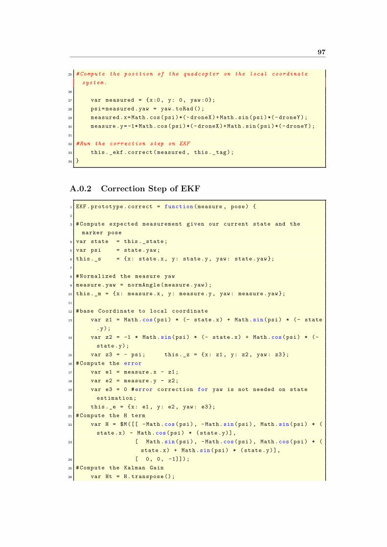
97
25 # Compute the position of the quadcopter on the local coordinatesystem .
26
27 var measured = {x:0, y: 0, yaw :0};28 psi= measured .yaw = yaw.toRad ();29 measured .x=Math.cos(psi)*(- droneX )+Math.sin(psi)*(- droneY );30 measure .y=-1* Math.cos(psi)*(- droneX )+Math.sin(psi)*(- droneY );31
32 #Run the correction step on EKF33 this._ekf. correct (measured , this._tag);34 }
A.0.2 Correction Step of EKF
1 EKF. prototype . correct = function (measure , pose) {2
3 # Compute expected measurement given our current state and themarker pose
4 var state = this. _state ;5 var psi = state .yaw;6 this._s = {x: state .x, y: state .y, yaw: state .yaw };7
8 # Normalized the measure yaw9 measure .yaw = normAngle ( measure .yaw);
10 this._m = {x: measure .x, y: measure .y, yaw: measure .yaw };11
12 #base Coordinate to local coordinate13 var z1 = Math.cos(psi) * (- state .x) + Math.sin(psi) * (- state
.y);14 var z2 = -1 * Math.sin(psi) * (- state.x) + Math.cos(psi) * (-
state .y);15 var z3 = - psi; this._z = {x: z1 , y: z2 , yaw: z3};16 # Compute the error17 var e1 = measure .x - z1;18 var e2 = measure .y - z2;19 var e3 = 0 # error correction for yaw is not needed on state
estimation ;20 this._e = {x: e1 , y: e2 , yaw: e3};21 # Compute the H term22 var H = $M ([[ -Math.cos(psi), -Math.sin(psi), Math.sin(psi) * (
state .x) - Math.cos(psi) * (state.y)],23 [ Math.sin(psi), -Math.cos(psi), Math.cos(psi) * (
state .x) + Math.sin(psi) * (state.y)],24 [ 0, 0, -1]]);25 # Compute the Kalman Gain26 var Ht = H. transpose ();

98
27 var K = this. _sigma . multiply (Ht). multiply (H. multiply (this._sigma ). multiply (Ht).add(this._r). inverse ())
28 # Correct the pose estimate29 var err = $V ([e1 , e2 , e3]);30 var c = K . multiply (err);31
32 var xcor= (c.e(1))*Math.cos(psi) - Math.sin(psi)*(c.e(2));33 var ycor =(c.e(1))*Math.sin(psi) + Math.cos(psi)*(c.e(2));34 state.x = state.x + xcor;35 state.y = state.y + ycor;36 this. _sigma = Matrix .I(3). subtract (K. multiply (H)). multiply (this
. _sigma );37 };
A.0.3 Mission planner to form a flight to collect data
1 # intial conditions for the flight2 global . fixedAltitude =15 //m3 global . fixedRotation =180;4 global . flyDistance =20;5 global . stepSize =1;6 # Control command to achieve the given altitude7 global . mysteps .push( function (cb){8 ARctrl . altitude ( global . fixedAltitude ,cb);9 });
10 # Control command to achieve the given orientation11 global . mysteps .push( function (cb) {12 ARctrl .cw( global . fixedRotation ,cb);13 });14
15 # Generate control command to make the quadcopter to fly in a givendirection with a interval of 5sec.
16
17 for(var i = stepSize ; i < global . flyDistance ; i=i+ stepSize ) {18 global . mysteps .push( function (cb){19 global . Flystatus ="Not Hovering ";20 global . flyingNow =true;21 ARctrl .go ({x:i,y:0,z: targetAltitude ,yaw: initialYaw });22 console .log(" moving forward ");23 });24 global . mysteps .push( function (cb){25 global . Flystatus =" Hovering ";26 ARctrl .hover ();27 setTimeout (cb , 5000) ;28 });29 }

99
30 global . mysteps .push( function (cb){31 global . Flystatus =" Landing ";32 global . flyingNow =false;33 ARclient .land(cb);34 });35
36 async . waterfall ( global . mysteps );

Appendix B
Data Sets
B.0.4 Data set on actual, predicted and GPS distance.
TargetDistance
Actual Predicted GPS Actual Error PredictedError
(Predicted -Actual)
GPS error(GPS-Actual)
5 5.4 5.16 6.634 0.4 0.24 1.2345 5.7 5.45 7.224 0.7 0.25 1.5245 6.6 5.42 8.3117 1.6 1.18 1.71175 5.3 4.92 6.1738 0.3 0.38 0.87385 5.8 5.21 6.167 0.8 0.59 0.36710 12.5 10.17 15.3923015 2.5 2.33 2.89230150410 11.2 9.99 12.12557644 1.2 1.21 0.9255764410 11.1 10.11 11.1642 1.1 0.99 0.064210 11 10.15 11.0544 1 0.85 0.054410 10.9 10.27 12.0012 0.9 0.63 1.101214 16.4 14.17 19.39102741 2.4 2.23 2.99102741414 15.5 14.18 16.3877811 1.5 1.32 0.88778110114 15 14.2 16.47394416 1 0.8 1.47394415814 16.1 14.24 17.46546186 2.1 1.86 1.36546185814 15.1 13.99 14.45235444 1.1 1.11 0.647645564

101
B.0.5 Sample data on distance and SNR changes over theflying status ( Flying or Hovering)
SNR Distance Flying Status25 8.41 126 8.42 127 8.41 128 8.39 129 8.37 130 8.33 131 8.29 133 6.35 136 6.43 137 6.61 139 4.49 141 4.48 145 4.49 154 2.39 124 8.48 225 8.41 231 8.43 233 6.82 237 5.17 245 4.56 247 4.02 254 2.41 2... ... ...... ... ...... ... ...
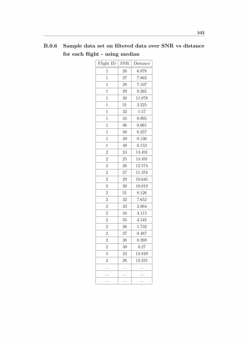
102
B.0.6 Sample data set on filtered data over SNR vs distancefor each flight - using median
Flight ID SNR Distance1 26 6.8781 27 7.8621 28 7.1071 29 9.2651 30 11.0781 31 3.2251 32 1.571 34 0.9051 36 0.6611 38 0.2571 39 0.1361 40 0.1532 24 13.4912 25 13.4912 26 12.5742 27 11.3782 29 10.6452 30 10.0192 31 8.1262 32 7.6522 33 3.8642 34 4.1152 35 4.5452 36 1.7322 37 0.4872 38 0.2692 39 0.273 23 13.8493 26 13.231... ... ...... ... ...... ... ...

103
B.0.7 Sample data set on filtered data on distance - medianand harmonic mean.
Set ID SNR Median Harmonic Mean1 26 6.8783 6.83831 27 7.8623 7.85921 28 7.1067 6.93271 29 9.2653 8.65101 30 11.0781 6.57671 31 3.2247 3.44021 32 1.5695 1.51091 34 .9045 .89961 36 .6613 .65561 38 .2572 .17561 39 .1362 .11161 40 .1534 .15332 24 13.4913 13.49132 25 13.4913 13.49132 26 12.5741 12.54732 27 11.3775 11.37342 29 10.6450 10.64032 30 10.0193 10.01772 31 8.1264 8.12312 32 7.6521 7.50042 33 3.8642 3.98612 34 4.1148 4.16842 35 4.5447 4.54152 36 1.7317 1.6523... ... ... ...... ... ... ...... ... ... ...
Related Documents