Cleaner Engineering and Technology 4 (2021) 100217 Available online 22 July 2021 2666-7908/© 2021 The Authors. Published by Elsevier Ltd. This is an open access article under the CC BY-NC-ND license (http://creativecommons.org/licenses/by-nc-nd/4.0/). A prototype of an energy-efficient MAGLEV train: A step towards cleaner train transport Zakria Qadir a , Arslan Munir b, *, 1 , Tehreem Ashfaq c , Hafiz Suliman Munawar d , Muazzam A. Khan e, ** , Khoa Le a a The School of Computing Engineering and Mathematics, Western Sydney University, Locked Bag 1797, Penrith, NSW 2751, Australia b The Department of Computer Science, Kansas State University, Manhattan, KS, USA c WeRplay, Islamabad, Pakistan d The University of New South Wales, Kensington, Sydney, NSW 2052, Australia e The Department of Computer Sciences, Quaid-i-Azam University, Islamabad, Pakistan A R T I C L E INFO Keywords: MAGLEV train Transportation systems Microcontroller Electromagnets Permanent magnets Infrared sensor Electrodynamic suspension ABSTRACT The magnetic levitation (MAGLEV) train uses magnetic field to suspend, guide, and propel vehicle onto the track. The MAGLEV train provides a sustainable and cleaner solution for train transportation by significantly reducing the energy usage and greenhouse gas emissions as compared to traditional train transportation systems. In this paper, we propose an advanced control mechanism using an Arduino microcontroller that selectively energizes the electromagnets in a MAGLEV train system to provide dynamic stability and energy efficiency. We also design the prototype of an energy-efficient MAGLEV train that leverages our proposed control mechanism. In our MAGLEV train prototype, the levitation is achieved by creating a repulsive magnetic field between the train and the track using magnets mounted on the top-side of the track and bottom-side of the vehicle. The propulsion is performed by creating a repulsive magnetic field between the permanent magnets attached on the sides of the vehicle and electromagnets mounted at the center of the track using electrodynamic suspension (EDS). The electromagnets are energized via a control mechanism that is applied through an Arduino microcontroller. The Arduino microcontroller is programmed in such a way to propel and guide the vehicle onto the track by appropriate switching of the electromagnets. We use an infrared-based remote-control device for controlling the power, speed, and direction of the vehicle in both the forward and the backward direction. The proposed MAGLEV train control mechanism is novel, and according to the best of our knowledge is the first study of its kind that uses an Arduino-based microcontroller system for control mechanism. Experimental results illustrate that the designed prototype consumes only 144 W-hour (Wh) of energy as compared to a conventionally designed MAGLEV train prototype that consumes 1200 Wh. Results reveal that our proposed control mechanism and prototype model can reduce the total power consumption by 8.3 × as compared to the traditional MAGLEV train prototype, and can be applied to practical MAGLEV trains with necessary modifications. Thus, our proposed prototype and control mechanism serves as a first step towards cleaner engineering of train transportation systems. 1. Introduction The energy crisis has exacerbated over the recent years as new technologies, devices, and systems are increasingly being developed that consume an enormous amount of energy. The transportation sector is one of the main consumers of energy (Mohanty, 2020; Umoren et al., 2020). The transportation sector energy consumption has been increasing at an annual average rate of 1.4%, from 104 quadrillion British thermal units (Btu) in 2012 to 155 quadrillion Btu in 2040 (Of- fice, 2016). Thus, reducing the energy consumption of transportation * Corresponding author. ** Corresponding author. E-mail addresses: [email protected] (Z. Qadir), [email protected] (A. Munir), [email protected] (T. Ashfaq), [email protected] (H.S. Munawar), [email protected] (M.A. Khan), [email protected] (K. Le). 1 Arslan Munir’s current address is 2162 Engineering Hall, 1701D Platt St, Manhattan, KS, 66,506, USA. Contents lists available at ScienceDirect Cleaner Engineering and Technology journal homepage: www.sciencedirect.com/journal/cleaner-engineering-and-technology https://doi.org/10.1016/j.clet.2021.100217 Received 16 March 2021; Received in revised form 10 July 2021; Accepted 15 July 2021

Welcome message from author
This document is posted to help you gain knowledge. Please leave a comment to let me know what you think about it! Share it to your friends and learn new things together.
Transcript
Cleaner Engineering and Technology 4 (2021) 100217
Available online 22 July 20212666-7908/© 2021 The Authors. Published by Elsevier Ltd. This is an open access article under the CC BY-NC-ND license(http://creativecommons.org/licenses/by-nc-nd/4.0/).
A prototype of an energy-efficient MAGLEV train: A step towards cleaner train transport
Zakria Qadir a, Arslan Munir b,*,1, Tehreem Ashfaq c, Hafiz Suliman Munawar d, Muazzam A. Khan e,**, Khoa Le a
a The School of Computing Engineering and Mathematics, Western Sydney University, Locked Bag 1797, Penrith, NSW 2751, Australia b The Department of Computer Science, Kansas State University, Manhattan, KS, USA c WeRplay, Islamabad, Pakistan d The University of New South Wales, Kensington, Sydney, NSW 2052, Australia e The Department of Computer Sciences, Quaid-i-Azam University, Islamabad, Pakistan
A R T I C L E I N F O
Keywords: MAGLEV train Transportation systems Microcontroller Electromagnets Permanent magnets Infrared sensor Electrodynamic suspension
A B S T R A C T
The magnetic levitation (MAGLEV) train uses magnetic field to suspend, guide, and propel vehicle onto the track. The MAGLEV train provides a sustainable and cleaner solution for train transportation by significantly reducing the energy usage and greenhouse gas emissions as compared to traditional train transportation systems. In this paper, we propose an advanced control mechanism using an Arduino microcontroller that selectively energizes the electromagnets in a MAGLEV train system to provide dynamic stability and energy efficiency. We also design the prototype of an energy-efficient MAGLEV train that leverages our proposed control mechanism. In our MAGLEV train prototype, the levitation is achieved by creating a repulsive magnetic field between the train and the track using magnets mounted on the top-side of the track and bottom-side of the vehicle. The propulsion is performed by creating a repulsive magnetic field between the permanent magnets attached on the sides of the vehicle and electromagnets mounted at the center of the track using electrodynamic suspension (EDS). The electromagnets are energized via a control mechanism that is applied through an Arduino microcontroller. The Arduino microcontroller is programmed in such a way to propel and guide the vehicle onto the track by appropriate switching of the electromagnets. We use an infrared-based remote-control device for controlling the power, speed, and direction of the vehicle in both the forward and the backward direction. The proposed MAGLEV train control mechanism is novel, and according to the best of our knowledge is the first study of its kind that uses an Arduino-based microcontroller system for control mechanism. Experimental results illustrate that the designed prototype consumes only 144 W-hour (Wh) of energy as compared to a conventionally designed MAGLEV train prototype that consumes 1200 Wh. Results reveal that our proposed control mechanism and prototype model can reduce the total power consumption by 8.3 × as compared to the traditional MAGLEV train prototype, and can be applied to practical MAGLEV trains with necessary modifications. Thus, our proposed prototype and control mechanism serves as a first step towards cleaner engineering of train transportation systems.
1. Introduction
The energy crisis has exacerbated over the recent years as new technologies, devices, and systems are increasingly being developed that consume an enormous amount of energy. The transportation sector is
one of the main consumers of energy (Mohanty, 2020; Umoren et al., 2020). The transportation sector energy consumption has been increasing at an annual average rate of 1.4%, from 104 quadrillion British thermal units (Btu) in 2012 to 155 quadrillion Btu in 2040 (Of-fice, 2016). Thus, reducing the energy consumption of transportation
* Corresponding author. ** Corresponding author.
E-mail addresses: [email protected] (Z. Qadir), [email protected] (A. Munir), [email protected] (T. Ashfaq), [email protected] (H.S. Munawar), [email protected] (M.A. Khan), [email protected] (K. Le).
1 Arslan Munir’s current address is 2162 Engineering Hall, 1701D Platt St, Manhattan, KS, 66,506, USA.
Contents lists available at ScienceDirect
Cleaner Engineering and Technology
journal homepage: www.sciencedirect.com/journal/cleaner-engineering-and-technology
https://doi.org/10.1016/j.clet.2021.100217 Received 16 March 2021; Received in revised form 10 July 2021; Accepted 15 July 2021
Cleaner Engineering and Technology 4 (2021) 100217
2
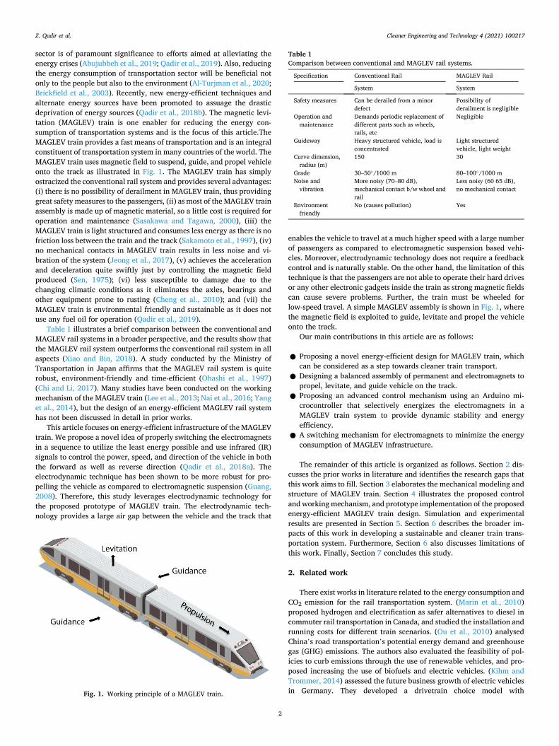
sector is of paramount significance to efforts aimed at alleviating the energy crises (Abujubbeh et al., 2019; Qadir et al., 2019). Also, reducing the energy consumption of transportation sector will be beneficial not only to the people but also to the environment (Al-Turjman et al., 2020; Brickfield et al., 2003). Recently, new energy-efficient techniques and alternate energy sources have been promoted to assuage the drastic deprivation of energy sources (Qadir et al., 2018b). The magnetic levi-tation (MAGLEV) train is one enabler for reducing the energy con-sumption of transportation systems and is the focus of this article.The MAGLEV train provides a fast means of transportation and is an integral constituent of transportation system in many countries of the world. The MAGLEV train uses magnetic field to suspend, guide, and propel vehicle onto the track as illustrated in Fig. 1. The MAGLEV train has simply ostracized the conventional rail system and provides several advantages: (i) there is no possibility of derailment in MAGLEV train, thus providing great safety measures to the passengers, (ii) as most of the MAGLEV train assembly is made up of magnetic material, so a little cost is required for operation and maintenance (Sasakawa and Tagawa, 2000), (iii) the MAGLEV train is light structured and consumes less energy as there is no friction loss between the train and the track (Sakamoto et al., 1997), (iv) no mechanical contacts in MAGLEV train results in less noise and vi-bration of the system (Jeong et al., 2017), (v) achieves the acceleration and deceleration quite swiftly just by controlling the magnetic field produced (Sen, 1975); (vi) less susceptible to damage due to the changing climatic conditions as it eliminates the axles, bearings and other equipment prone to rusting (Cheng et al., 2010); and (vii) the MAGLEV train is environmental friendly and sustainable as it does not use any fuel oil for operation (Qadir et al., 2019).
Table 1 illustrates a brief comparison between the conventional and MAGLEV rail systems in a broader perspective, and the results show that the MAGLEV rail system outperforms the conventional rail system in all aspects (Xiao and Bin, 2018). A study conducted by the Ministry of Transportation in Japan affirms that the MAGLEV rail system is quite robust, environment-friendly and time-efficient (Ohashi et al., 1997) (Chi and Li, 2017). Many studies have been conducted on the working mechanism of the MAGLEV train (Lee et al., 2013; Nai et al., 2016; Yang et al., 2014), but the design of an energy-efficient MAGLEV rail system has not been discussed in detail in prior works.
This article focuses on energy-efficient infrastructure of the MAGLEV train. We propose a novel idea of properly switching the electromagnets in a sequence to utilize the least energy possible and use infrared (IR) signals to control the power, speed, and direction of the vehicle in both the forward as well as reverse direction (Qadir et al., 2018a). The electrodynamic technique has been shown to be more robust for pro-pelling the vehicle as compared to electromagnetic suspension (Guang, 2008). Therefore, this study leverages electrodynamic technology for the proposed prototype of MAGLEV train. The electrodynamic tech-nology provides a large air gap between the vehicle and the track that
enables the vehicle to travel at a much higher speed with a large number of passengers as compared to electromagnetic suspension based vehi-cles. Moreover, electrodynamic technology does not require a feedback control and is naturally stable. On the other hand, the limitation of this technique is that the passengers are not able to operate their hard drives or any other electronic gadgets inside the train as strong magnetic fields can cause severe problems. Further, the train must be wheeled for low-speed travel. A simple MAGLEV assembly is shown in Fig. 1, where the magnetic field is exploited to guide, levitate and propel the vehicle onto the track.
Our main contributions in this article are as follows:
● Proposing a novel energy-efficient design for MAGLEV train, which can be considered as a step towards cleaner train transport.
● Designing a balanced assembly of permanent and electromagnets to propel, levitate, and guide vehicle on the track.
● Proposing an advanced control mechanism using an Arduino mi-crocontroller that selectively energizes the electromagnets in a MAGLEV train system to provide dynamic stability and energy efficiency.
● A switching mechanism for electromagnets to minimize the energy consumption of MAGLEV infrastructure.
The remainder of this article is organized as follows. Section 2 dis-cusses the prior works in literature and identifies the research gaps that this work aims to fill. Section 3 elaborates the mechanical modeling and structure of MAGLEV train. Section 4 illustrates the proposed control and working mechanism, and prototype implementation of the proposed energy-efficient MAGLEV train design. Simulation and experimental results are presented in Section 5. Section 6 describes the broader im-pacts of this work in developing a sustainable and cleaner train trans-portation system. Furthermore, Section 6 also discusses limitations of this work. Finally, Section 7 concludes this study.
2. Related work
There exist works in literature related to the energy consumption and CO2 emission for the rail transportation system. (Marin et al., 2010) proposed hydrogen and electrification as safer alternatives to diesel in commuter rail transportation in Canada, and studied the installation and running costs for different train scenarios. (Ou et al., 2010) analysed China’s road transportation’s potential energy demand and greenhouse gas (GHG) emissions. The authors also evaluated the feasibility of pol-icies to curb emissions through the use of renewable vehicles, and pro-posed increasing the use of biofuels and electric vehicles. (Kihm and Trommer, 2014) assessed the future business growth of electric vehicles in Germany. They developed a drivetrain choice model with Fig. 1. Working principle of a MAGLEV train.
Table 1 Comparison between conventional and MAGLEV rail systems.
Specification Conventional Rail MAGLEV Rail
System System
Safety measures Can be derailed from a minor defect
Possibility of derailment is negligible
Operation and maintenance
Demands periodic replacement of different parts such as wheels, rails, etc
Negligible
Guideway Heavy structured vehicle, load is concentrated
Light structured vehicle, light weight
Curve dimension, radius (m)
150 30
Grade 30–50◦/1000 m 80–100◦/1000 m Noise and
vibration More noisy (70–80 dB), mechanical contact b/w wheel and rail
Less noisy (60 65 dB), no mechanical contact
Environment friendly
No (causes pollution) Yes
Z. Qadir et al.

Cleaner Engineering and Technology 4 (2021) 100217
3
economical, technical and social constraints on the current vehicle registrations and inventory. They discovered that electric vehicles would be able to replace gasoline and diesel engines, and would sup-plant almost one-third of Germany’s overall annual fuel consumption. (Janic, 2020) developed analytical models for the estimation of direct energy consumption and related emissions of GHG exclusively, including CO2, by the high speed rail (HSR), trans rapid Maglev (TRM), and hyperloop (HL) passenger transport systems. The majority of pre-vious works focused on estimation of GHG including CO2 emissions of transport systems; however, there is no literature on MAGLEV train hybrid models that use permanent magnets and electromagnets, and that incorporate a microcontroller-based switching scheme to make the MAGLEV train energy-efficient and environment-friendly.
Some previous works also studied the control strategies for MAGLEV train. (Gao et al., 2019) proposed an electromagnetic damping structure into the vehicle suspension frame to create a hybrid suspension control system comprising of permanent magnets and electromagnets. The proposed system realized zero suspension power compared to the traditional hybrid suspension system. Moreover, the energy was consumed only at the instant when the electromagnetic suspension was regulated. However, no significant improvement for overall energy consumption was observed. (Wu et al., 2021) proposed an approach to simultaneously optimize the train operation, timetable, and energy management technique of the on-board energy storage device (OESD) to minimize the net energy consumption for a whole urban railway line. The authors first tested their proposed system for several general train cases to verify its efficacy. The authors then implemented their proposed system in real-world, and observed that the proposed solution resulted in the net energy consumption improvement of a single train by 1.04% using the fully charged scenario. However, our proposed model results in energy savings of 8.3 × . (Rickwartz et al., 2020) proposed a control strategy for hybrid actuators that combine permanent magnet and electromagnetic forces for a MAGLEV train model to achieve dynamic stability. They tested the proposed controller in a laboratory setting on a scale of 1:20. However, the work didn’t report the energy improvements afforded by the proposed control system.
To overcome the deficiencies in prior works, we have developed a prototype for an energy-efficient MAGLEV train and a microcontroller- based control strategy of electromagnets that can result in energy sav-ings of 8.3 × over contemporary MAGLEV train designs.
3. MAGLEV train structure
In the design of our energy-efficient MAGLEV train prototype, both the mechanical and electrical structures are implemented.
3.1. Mechanical structure
Considering that the mechanical structure of the MAGLEV train, the
levitation system, and the mounting of magnets (both the permanent magnets and electromagnets) are of paramount importance, a detailed mechanical assembly showing the arrangement of electromagnets, and vehicle and track design is illustrated in Fig. 2. The levitation magnets help levitate the vehicle in the air, almost 4–5 mm above the guideway. The accurate placement of the permanent magnet makes the repulsive force so strong that the vehicle remains levitated in the air even when it is running. A guidance magnet is mounted on both sides of the vehicle along its entire length so the vehicle does not run off its track, and proper guidance can be provided to it along the track. Moreover, these magnets are mounted in a way to provide an appropriate mechanism of repulsion.
In the designed prototype, the total length of the track is 106 cm, while the effective length of the track due to magnets is 102 cm (≈1 m). The width of the track is 15 cm. The proposed track comprises of eight sections in total, where seven sections consist of three electromagnetic coils, and the eighth section consists of four electromagnetic coils. For the designed prototype, the stable speed is determined by the pole pitch of the track coil and the pole pitch of the permanent magnet. The pole pitch is calculated based on the work by (Dong et al., 2019a). The pole pitch between the two electromagnets comes out to be 37.4 mm, and for permanent magnet it is 27.4 mm.
3.1.1. Structural design of electromagnets The bobbin is designed using carved plastic sheets, across which the
copper coil is accurately wrapped as shown in Fig. 3. There are two main advantages of using the bobbin: (i) it will make the overall system lightweight, and (ii) the plastic will have no effect on the magnetic fields generated by the permanent or the electromagnets.After the bobbin is designed, the copper wire or coil is then wounded over the bobbin in a specific arrangement. The proposed design consists of a total of 130 turns which are wrapped across the bobbin to produce an accurate magnetic field. When a current of 3–5 A (A) passes through the bobbin with coil structure, it becomes an electromagnet. The designed elec-tromagnets are then placed inside two parallel plastic sheets having equally spaced holes. Moreover, the structure dimensions are calculated to hold and assemble twenty-five of the electromagnets tightly.
3.1.2. Structural design of permanent magnets The permanent magnets known as levitation magnets are mounted
on the side of the vehicle to levitate over the track. The six permanent magnets are used for levitating the train, while eight of them are placed vertically in the centre, such that they interact with the magnetic field produced by the electromagnets. The generated mechanical force from the electromagnet helps in propelling the vehicle over the track.
The main purpose of using both the electromagnets and the perma-nent magnets is to levitate and propel the vehicle and is further explained below:
Fig. 2. Mechanical structure of MAGLEV train: (a) arrangement of electromagnets, (b) vehicle design, (c) vehicle and track design.
Z. Qadir et al.

Cleaner Engineering and Technology 4 (2021) 100217
4
● Levitation: The permanent magnets used for levitating the vehicle consist of fifty magnets mounted on the track, in total, and six magnets mounted onto the vehicle. This assembly prevents the vehicle from any direct mechanical contact to the track, thus avoiding any friction losses. The electrodynamic suspension (EDS) approach is leveraged to provide a repulsion mechanism, which help levitate the vehicle on the track (Hogan and Fink, 1975).
● Propulsion: The electromagnets mounted in the centre of the track produces the magnetic field when energized by a power source. This magnetic field interacts with the permanent magnets which are placed at the bottom of the vehicle and are aligned with the elec-tromagnets as shown in Fig. 4 (Sun et al., 2020). It is to be noted that the permanent magnets help in both levitation and propulsion of the vehicle, and thus are mounted at the bottom as well as on the sides of the vehicle as illustrated in Fig. 2 (b). The proper spacing and sequencing between the permanent magnets and the electromagnets create a repulsion mechanism which help propel the vehicle. The direction of the propulsion can be set to both forward and reverse as desired.
3.2. Calculating magnetic field strength of electromagnets
The number of turns, current, and the radius of the coil determine the magnetic field strength of electromagnets. In our designed prototype, the copper wire wrapped across the bobbin has a diameter of 2.54 mm, and the total number of turns is 130. When the current of 4 A passes through the wrapped coil, it becomes an electromagnet having north and south poles according to the right-hand rule.In the designed pro-totype, the coil used in the design of electromagnets has a wire gauge of 23 μm, its diameter (D) is 2.54 cm and length (L) is 4.08 cm as shown in Fig. 5. The magnetic field strength of the electromagnet can be
calculated as (Nai et al., 2016; Yang et al., 2014):
B = μNI/L = Φ/A (1)
where B is the magnetic induction or magnetic flux density produced by the electromagnetic coil in tesla (T) and is inversely proportional to the area (A) defined by the electric coil/wire wrapped across the bobbin, Φ is the magnetic flux generated by the electromagnet, μ is the perme-ability of air and is equal to 1.25663753 × 10− 6 T m/A, N is the total number of turns in the coil, I is the current used to energize the coil to produce the desired magnetic field, and L is the length of the electro-magnetic coil. In the designed prototype, using the values of N (130), I (4 A), and L (4.08 cm = 0.0408 m), B comes out to be 0.01602 T from Eq. (1).
4. MAGLEV train working and control mechanism
This section elaborates the working and control mechanism of the proposed energy-efficient MAGLEV train.
Fig. 3. Electromagnetic design: (a) bobbin, and (b) electromagnets.
Fig. 4. Electromagnets and permanent magnets placement.
Fig. 5. Dimensions of the electromagnet.
Z. Qadir et al.
Cleaner Engineering and Technology 4 (2021) 100217
5
4.1. Working mechanism
The working principle of the proposed MAGLEV train is based on electrodynamic suspension. In order to provide a smooth operation for the train, permanent magnets are mounted on the bottom of the vehicle for levitation and on the sides of the vehicle for propulsion. This arrangement allows the vehicle and track to have no mechanical contact with each other, and thus the vehicle can easily move along the track in the air medium. The vehicle and the track both use permanent magnets to levitate the vehicle and provide the necessary suspension mechanism. The permanent magnets attached to the bottom of the vehicle come into the vicinity of the magnetic field produced by electromagnets and pro-vide stability to the vehicle in the vertical direction.
The magnetic field generated by the permanent magnets provides strong repulsive force and thus stabilizes the vehicle, which, according to Earnshaw’s theorem, is necessary for levitation. The principle of electromagnetic propulsion depends on the polarity of the electro-magnet, that is, the opposite poles attract each other while the same poles repel each other. In the designed prototype, the repulsive mech-anism is used for propelling the vehicle on the track. The electromagnets mounted on the centre of the track provides the same polarities (North- North or South-South), and thus the repulsion propels the vehicle.
Suspension or levitation force and coil current are directly related. The suspension force is zero for no (zero) coil current and the suspension force increases as the current given to the coil increases. The suspension force also depends on the air gap (i.e., the gap between the vehicle and the track) where the high air gaps cause non linearity between the strength of the magnetic field and the coil current. The linkage between the suspension force F and the current I is given as follows (Xiao et al., 2018):
F =B2WS
μ0L, (2)
where
B =μ0μNI
2Zμ + μ0[2h + (1 + WS/Td)b]L, (3)
where B is the magnetic field, WS is the magnetic pole width of the electromagnet, L is the longitudinal length of suspension structure, μ0 is the permeability of free space (4π × 10− 7 N/A2), Td is the magnetic yoke height of the suspension rail, h is the magnetic yoke height of the elec-tromagnet, Z is the air gap of the suspension structure and b is the magnetic yoke width of the electromagnet.
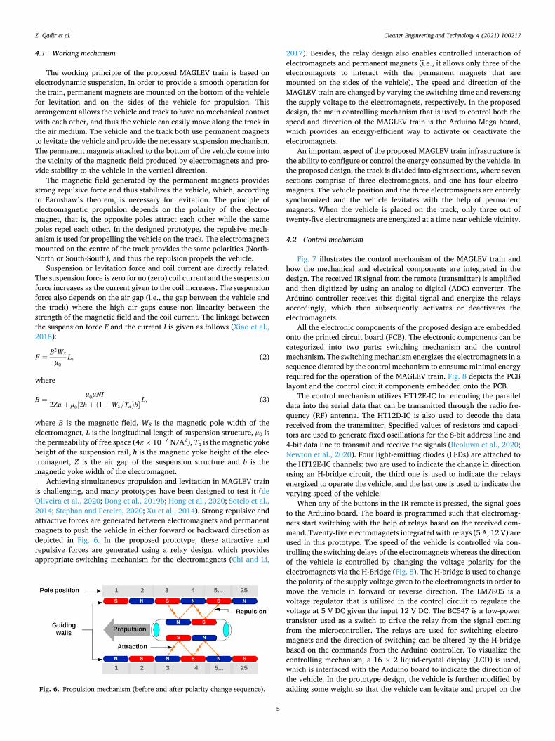
Achieving simultaneous propulsion and levitation in MAGLEV train is challenging, and many prototypes have been designed to test it (de Oliveira et al., 2020; Dong et al., 2019b; Hong et al., 2020; Sotelo et al., 2014; Stephan and Pereira, 2020; Xu et al., 2014). Strong repulsive and attractive forces are generated between electromagnets and permanent magnets to push the vehicle in either forward or backward direction as depicted in Fig. 6. In the proposed prototype, these attractive and repulsive forces are generated using a relay design, which provides appropriate switching mechanism for the electromagnets (Chi and Li,
2017). Besides, the relay design also enables controlled interaction of electromagnets and permanent magnets (i.e., it allows only three of the electromagnets to interact with the permanent magnets that are mounted on the sides of the vehicle). The speed and direction of the MAGLEV train are changed by varying the switching time and reversing the supply voltage to the electromagnets, respectively. In the proposed design, the main controlling mechanism that is used to control both the speed and direction of the MAGLEV train is the Arduino Mega board, which provides an energy-efficient way to activate or deactivate the electromagnets.
An important aspect of the proposed MAGLEV train infrastructure is the ability to configure or control the energy consumed by the vehicle. In the proposed design, the track is divided into eight sections, where seven sections comprise of three electromagnets, and one has four electro-magnets. The vehicle position and the three electromagnets are entirely synchronized and the vehicle levitates with the help of permanent magnets. When the vehicle is placed on the track, only three out of twenty-five electromagnets are energized at a time near vehicle vicinity.
4.2. Control mechanism
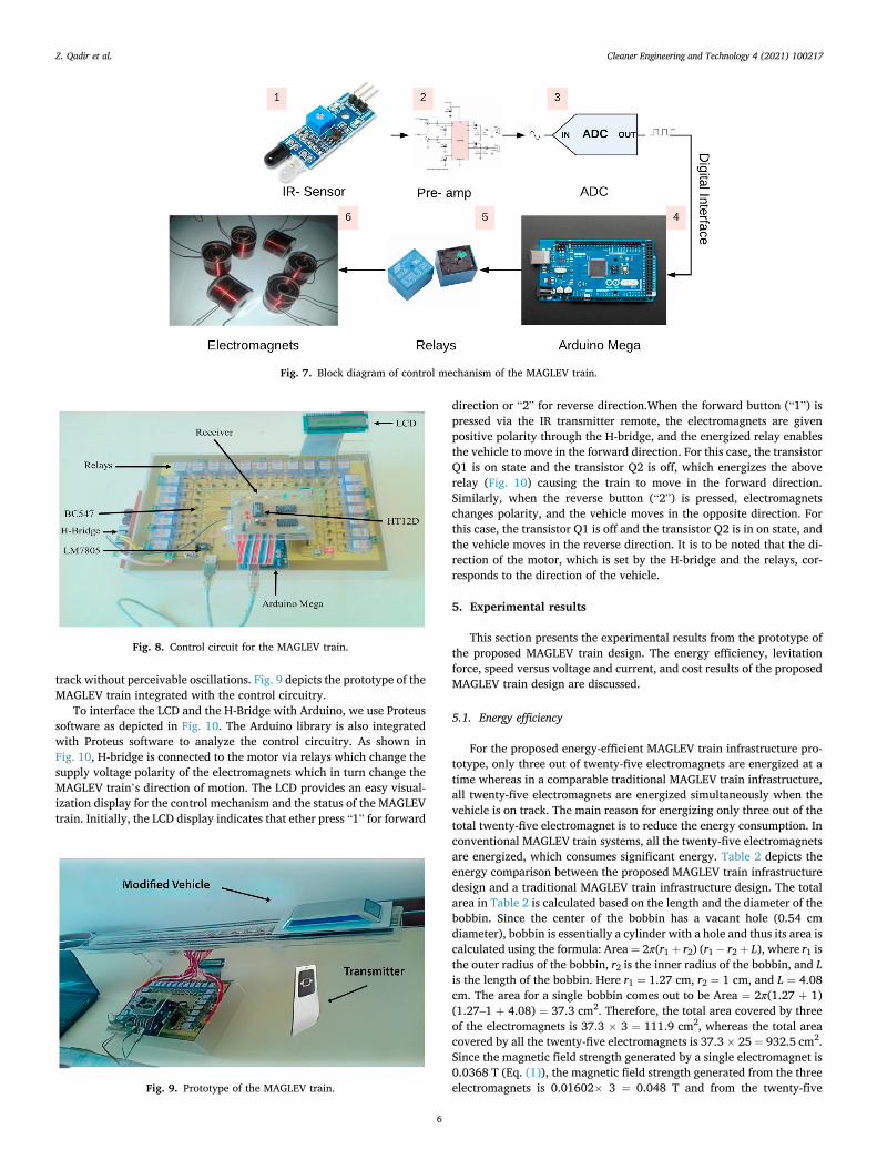
Fig. 7 illustrates the control mechanism of the MAGLEV train and how the mechanical and electrical components are integrated in the design. The received IR signal from the remote (transmitter) is amplified and then digitized by using an analog-to-digital (ADC) converter. The Arduino controller receives this digital signal and energize the relays accordingly, which then subsequently activates or deactivates the electromagnets.
All the electronic components of the proposed design are embedded onto the printed circuit board (PCB). The electronic components can be categorized into two parts: switching mechanism and the control mechanism. The switching mechanism energizes the electromagnets in a sequence dictated by the control mechanism to consume minimal energy required for the operation of the MAGLEV train. Fig. 8 depicts the PCB layout and the control circuit components embedded onto the PCB.
The control mechanism utilizes HT12E-IC for encoding the parallel data into the serial data that can be transmitted through the radio fre-quency (RF) antenna. The HT12D-IC is also used to decode the data received from the transmitter. Specified values of resistors and capaci-tors are used to generate fixed oscillations for the 8-bit address line and 4-bit data line to transmit and receive the signals (Ifeoluwa et al., 2020; Newton et al., 2020). Four light-emitting diodes (LEDs) are attached to the HT12E-IC channels: two are used to indicate the change in direction using an H-bridge circuit, the third one is used to indicate the relays energized to operate the vehicle, and the last one is used to indicate the varying speed of the vehicle.
When any of the buttons in the IR remote is pressed, the signal goes to the Arduino board. The board is programmed such that electromag-nets start switching with the help of relays based on the received com-mand. Twenty-five electromagnets integrated with relays (5 A, 12 V) are used in this prototype. The speed of the vehicle is controlled via con-trolling the switching delays of the electromagnets whereas the direction of the vehicle is controlled by changing the voltage polarity for the electromagnets via the H-Bridge (Fig. 8). The H-bridge is used to change the polarity of the supply voltage given to the electromagnets in order to move the vehicle in forward or reverse direction. The LM7805 is a voltage regulator that is utilized in the control circuit to regulate the voltage at 5 V DC given the input 12 V DC. The BC547 is a low-power transistor used as a switch to drive the relay from the signal coming from the microcontroller. The relays are used for switching electro-magnets and the direction of switching can be altered by the H-bridge based on the commands from the Arduino controller. To visualize the controlling mechanism, a 16 × 2 liquid-crystal display (LCD) is used, which is interfaced with the Arduino board to indicate the direction of the vehicle. In the prototype design, the vehicle is further modified by adding some weight so that the vehicle can levitate and propel on the Fig. 6. Propulsion mechanism (before and after polarity change sequence).
Z. Qadir et al.
Cleaner Engineering and Technology 4 (2021) 100217
6
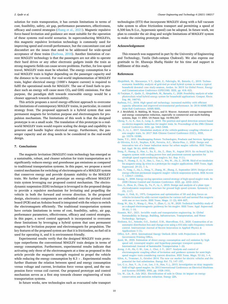
track without perceivable oscillations. Fig. 9 depicts the prototype of the MAGLEV train integrated with the control circuitry.
To interface the LCD and the H-Bridge with Arduino, we use Proteus software as depicted in Fig. 10. The Arduino library is also integrated with Proteus software to analyze the control circuitry. As shown in Fig. 10, H-bridge is connected to the motor via relays which change the supply voltage polarity of the electromagnets which in turn change the MAGLEV train’s direction of motion. The LCD provides an easy visual-ization display for the control mechanism and the status of the MAGLEV train. Initially, the LCD display indicates that ether press “1” for forward
direction or “2” for reverse direction.When the forward button (“1”) is pressed via the IR transmitter remote, the electromagnets are given positive polarity through the H-bridge, and the energized relay enables the vehicle to move in the forward direction. For this case, the transistor Q1 is on state and the transistor Q2 is off, which energizes the above relay (Fig. 10) causing the train to move in the forward direction. Similarly, when the reverse button (“2”) is pressed, electromagnets changes polarity, and the vehicle moves in the opposite direction. For this case, the transistor Q1 is off and the transistor Q2 is in on state, and the vehicle moves in the reverse direction. It is to be noted that the di-rection of the motor, which is set by the H-bridge and the relays, cor-responds to the direction of the vehicle.
5. Experimental results
This section presents the experimental results from the prototype of the proposed MAGLEV train design. The energy efficiency, levitation force, speed versus voltage and current, and cost results of the proposed MAGLEV train design are discussed.
5.1. Energy efficiency
For the proposed energy-efficient MAGLEV train infrastructure pro-totype, only three out of twenty-five electromagnets are energized at a time whereas in a comparable traditional MAGLEV train infrastructure, all twenty-five electromagnets are energized simultaneously when the vehicle is on track. The main reason for energizing only three out of the total twenty-five electromagnet is to reduce the energy consumption. In conventional MAGLEV train systems, all the twenty-five electromagnets are energized, which consumes significant energy. Table 2 depicts the energy comparison between the proposed MAGLEV train infrastructure design and a traditional MAGLEV train infrastructure design. The total area in Table 2 is calculated based on the length and the diameter of the bobbin. Since the center of the bobbin has a vacant hole (0.54 cm diameter), bobbin is essentially a cylinder with a hole and thus its area is calculated using the formula: Area = 2π(r1 + r2) (r1 − r2 + L), where r1 is the outer radius of the bobbin, r2 is the inner radius of the bobbin, and L is the length of the bobbin. Here r1 = 1.27 cm, r2 = 1 cm, and L = 4.08 cm. The area for a single bobbin comes out to be Area = 2π(1.27 + 1) (1.27–1 + 4.08) = 37.3 cm2. Therefore, the total area covered by three of the electromagnets is 37.3 × 3 = 111.9 cm2, whereas the total area covered by all the twenty-five electromagnets is 37.3 × 25 = 932.5 cm2. Since the magnetic field strength generated by a single electromagnet is 0.0368 T (Eq. (1)), the magnetic field strength generated from the three electromagnets is 0.01602× 3 = 0.048 T and from the twenty-five
Fig. 7. Block diagram of control mechanism of the MAGLEV train.
Fig. 8. Control circuit for the MAGLEV train.
Fig. 9. Prototype of the MAGLEV train.
Z. Qadir et al.

Cleaner Engineering and Technology 4 (2021) 100217
7
electromagnets is 0.01602 × 25 = 0.4 T as indicated in Table 2 for the proposed MAGLEV system and the traditional MAGLEV system, respectively.
Results indicate that the energy consumed by the proposed energy- efficient MAGLEV train system is only 144 Wh using only three of the twenty-five electromagnets at a time; however, the inefficient system consumes 1200 Wh of energy using twenty-five electromagnets. More-over, the results show that the magnetic field strength generated by the proposed energy-efficient system is smaller as compared to the tradi-tional energy-inefficient system. However, the proposed energy-efficient system generates enough magnetic strength to propel the vehicle, and the additional strength generated by the traditional energy-inefficient system is just wasted and can cause distortion or problem in the pro-pulsion of the vehicle by interacting with the field of neighbouring magnets.
5.2. Speed and energy consumption versus voltage and current
Speed of the vehicle is an important metric as it determines the journey or travel time for the passengers. In our experiments, we mea-sure the speed from the time taken by the MAGLEV train to reach from one end to the other end of the track using the relation v = s/t where v is the speed, s is the distance (i.e., length of the track) and t is the time taken by the vehicle to travel over the track length. In a set of experi-ments, we vary the current and voltage values and see the effect on the speed and energy consumption of the two train systems (i.e., proposed energy-efficient system and the traditional energy-inefficient system).
Fig. 11 shows the effect of change in voltage and current on energy consumption and speed of the proposed energy-efficient MAGLEV sys-tem. Results indicate that as the supply voltage or current increases, energy consumption and speed of the train also increase. The minimal voltage and current values set for our proposed system are 12 V and 4 A,
respectively, which are enough to propel the vehicle, and at these voltage and current values, the energy consumed by the three active electromagnets in the proposed MAGLEV system is only 144 Wh. As we increase the voltage to 24 V and 36 V, the energy consumption and speed linearly increases to 288 Wh and 432 Wh, and 1 m/s and 2 m/s, respectively. Similarly, as the current increase (4 A, 10 A), the energy consumption also increases (48 Wh, 120 Wh) while keeping the voltage constant at 12 V; however, the power consumption saturates and re-mains constant beyond a certain level of current. For our prototype system, 36 V and 10 A are the maximum voltage and current values for which the system can operate correctly beyond which the system mal-functions. It is to be noted that voltage and current are directly related to power, according to the relation, Power = Voltage × Current.
As the track in our prototype MAGLEV system has a length of 1 m, the vehicle speed reaches 0.5 m/s at minimal voltage of 12 V; however, the vehicle speed increases twice for 24 V and four times for 36 V, respec-tively. An increase in voltage or current results in stronger magnetic fields of electromagnets; hence, the vehicle experiences a stronger push which results in higher speed. Nevertheless, an increase in voltage or current also causes an increase in energy consumption of the MAGLEV system. Hence, a trade-off between energy consumption and speed needs to be made to make the MAGLEV system more energy-efficient at a nominal speed. As electromagnetic coil has its characteristic proper-ties, when the current is increased beyond a certain limit, the generated magnetic fields start to saturate and the energy consumption remains constant after that time (360 Wh and 10 A for our prototype system). It is to be noted that the timing sequence of the relay is negligible (in order of nanoseconds) and the switching time for electromagnets is very fast and does not cause any noticeable time delays for the designed prototype.
For a comparable traditional MAGLEV system prototype, as the number of active electromagnetic coils at a time is 25, the system results in higher energy consumption of 1200 Wh when the voltage is 12 V (nominal) and further increases linearly with the increase in voltage. Results (Fig. 12) show that the energy consumption of a comparable traditional MAGLEV system is 3600 Wh at 36 V, which is 8 × higher than the proposed energy-efficient MAGLEV system. As three of the electro-magnets are connected in series so the current flow is the same in the proposed MAGLEV prototype and increases proportionally in the tradi-tional MAGLEV prototype as can be seen from Figs. 11c and 12c.
Fig. 13 presents an energy consumption comparison between the proposed energy-efficient and traditional energy-inefficient MAGLEV systems. Results show that the proposed energy-efficient system
Fig. 10. Interfacing LCD and H-bridge with Arduino.
Table 2 Energy consumption of MAGLEV train.
MAGLEV train Proposed Design Traditional Design
No. Of electro- 3 25 magnets energized Current(A) 4 4 Voltage (V) 12 12 Energy consumed (Wh) 144 1200 Area (cm2)/coil 111.9 932.5 Magnetic field strength (T) 0.048 0.4
Z. Qadir et al.

Cleaner Engineering and Technology 4 (2021) 100217
8
Fig. 11. Speed and energy consumption vs voltage and current for the pro-posed energy-efficient system.
Fig. 12. Speed and energy consumption vs voltage and current for a traditional energy-inefficient system.
Z. Qadir et al.

Cleaner Engineering and Technology 4 (2021) 100217
9
consumes much lesser energy as compared to the traditional energy- inefficient MAGLEV system. Results indicate that the proposed energy- efficient system saves 8.3 × energy at 12 V, 24 V, and 36 V as compared to the traditional energy-inefficient MAGLEV system.
5.3. Levitation force versus speed
Our proposed MAGLEV system design uses the magnets in north (N) and south (S) poles configuration for propulsion of the vehicle on the track. It is interesting to see the impact of changing magnetic fields on the levitation force which directly affects the vehicle speed as shown in Fig. 14. Recent research (Guo et al., 2019) indicates that the N–S ar-ranged magnets not only generate higher levitation force but also help keep the vehicle stable and steadily increase its speed rather than abrupt changes in speed.
5.4. Suspension force and speed
Fig. 15 illustrates the relationship between suspension force and coil current for three different air-gaps (i.e., clearance between guideway surface and the supporting magnets for preventing physical contact).
Results show that the suspension force (F) is directly related to the coil current (I). When the coil current is zero, suspension force at this point is also zero. Suspension force increases gradually as the current given to the coil increases. For our proposed MAGLEV train design, we assume the air gap to be 2 mm in order to avoid the magnetic non-linearity experienced due to the higher air gaps as illustrated in Fig. 15 (Xiao et al., 2018).
5.5. Cost
The overall cost of the proposed prototype is less than $85 as the permanent magnets (total no.: 62 ≈ $20) used have necessary magnetic strength to levitate the vehicle and the copper coil (10 m length ≈ $15) used is of 23 μm gauge to propel the vehicle on the track. The me-chanical structure is made of plastic glass which cost approximately $5, the controlling mechanism (the PCB embedded with electronics com-ponents) and the miscellaneous cost is less than $40. Thus, the proposed prototype is economical for small-scale study of MAGLEV systems. Of course, the cost for real MAGLEV design will be much higher as the mechanical design would be metallic; however, only the cost of initial deployment will be high and would be compensated over the long run with reduced energy consumption.
6. Broader impacts and limitations
MAGLEV technology has emerged as a sustainable, robust, and cleaner solution for train transportation considering the increasing de-mand on transportation systems, energy needs for transportation sys-tems, and the effect of fuel consumption of traditional transportation systems on global climate (Liu and Lin, 2021). Furthermore, the accel-erated growth of transportation systems has exacerbated the stress on depleting energy sources and has resulted in exorbitant GHG emissions (Daim, 2021). Contrary to other modes of transportation systems, MAGLEV transportation has a large carrying capacity, a long trans-portation path, high speed, and low noise (Shinde et al., 2018). MAGLEV transportation uses significantly less electricity and emits significantly less CO2 per vehicle than the road and air transportation (Hossain, 2021). Reduced energy usage per unit of transportation translates to improved resource management and energy consumption, as well as lower transportation costs (Wang et al., 2021).
Although MAGLEV technology provides a sustainable and cleaner
Fig. 13. Comparison between the proposed energy-efficient and traditional energy-inefficient MAGLEV systems.
Fig. 14. Levitation force vs. speed (adapted from (Guo et al., 2019)).
Fig. 15. Suspension force vs. coil current for different air-gaps (adapted from (Xiao et al., 2018)).
Z. Qadir et al.
Cleaner Engineering and Technology 4 (2021) 100217
10
solution for train transporation, it has certain limitations in terms of cost, feasibility, safety, air gap, performance parameters, effectiveness, efficacy and control strategies (Zhang et al., 2021). Magnetic repulsive force-based levitation and guidance are most suitable for the operation of these systems real-world scenarios. In superconducting MAGLEVs, this magnetic repulsive levitation technology is commonly used for improving speed and overall performance, but the concomitant cost and discomfort are the issues that need to be addressed for wide-spread acceptance of these trains (Barbosa, 2018). Another limitation of cur-rent MAGLEV technology is that the passengers are not able to operate their hard drives or any other electronic gadgets inside the train as strong magnetic fields can cause severe problems. Further, for low-speed travel, MAGLEV train must be wheeled. The energy consumption for a real MAGLEV train is higher depending on the passenger capacity and the distance to be covered. For real-world implementation of MAGLEV train, higher electrical energy (1000’s Ampere current) is required to fulfil the operational needs for MAGLEV. The use of fossil fuels to pro-duce such an energy will cause more CO2 and GHG emissions. For that purpose, the paradigm shift towards renewable energy would be a cleaner approach towards sustainability.
This article proposes a novel energy-efficient approach to overcome the limitations of contemporary MAGLEV trains, in particular, in control strategy front. The proposed approach is a hybrid system that uses permanent magnets for levitation purpose and electromagnets for pro-pulsion mechanism. The limitations of this work is that the designed prototype is on a small scale. The translation of this prototype to a real- world MAGLEV train would require scaling the design and capability to generate and handle higher electrical energy. Furthermore, the pas-senger capacity and air drag needs to be considered in the real-world design.
7. Conclusions
The magnetic levitation (MAGLEV) train technology has emerged as a sustainable, robust, and cleaner solution for train transportation as it significantly reduces energy and greenhouse gas emissions as compared to traditional transportation systems. In this paper, we propose a novel control mechanism for switching of electromagnets of a MAGLEV system that conserves energy and provide dynamic stability to the MAGLEV train. We further design and prototype an energy-efficient MAGLEV train system leveraging our proposed control mechanism. The electro-dynamic suspension (EDS) technique is leveraged in the proposed design to provide a repulsive mechanism for levitating and propelling the vehicle in both the forward and reverse direction. In the proposed design, electronics components are embedded onto the printed circuit board (PCB) and an Arduino board is integrated with the relays to switch the electromagnets efficiently. The traditional transportation systems have certain limitations in terms of cost, feasibility, safety, air gap, performance parameters, effectiveness, efficacy and control strategies. In this paper, a novel control approach is incorporated to overcome these limitations by leveraging a hybrid system that uses permanent magnets for levitation purpose and electromagnets for propulsion. The key features of the proposed system are that it is frictionless, no fuel oil is used for operating it, and it is environment-friendly.
Experimental results verify that the designed MAGLEV train proto-type outperforms the conventional MAGLEV train designs in terms of energy consumption. Furthermore, experimental results indicate that activating only three of the electromagnets at a time as proposed in this article provide the magnetic strength required to propel the vehicle while reducing the energy consumption by 8.3 × . Experimental results further illustrate the relation between speed and energy consumption versus voltage and current, levitation force versus speed, and the sus-pension force versus coil current. Our proposed prototype and control mechanism serves as a first step towards cleaner engineering of train transportation systems.
In future works, new technologies such as evacuated tube transport
technologies (ET3) that incorporate MAGLEV along with a full vacuum tube system to allow frictionless transport and permitting a speed of 6,500 km/h (i.e., hypersonic speed) can be adopted. In future work, we plan to consider the air drag and weight limitations of MAGLEV system to make the existing prototype robust.
Acknowledgement
This research was supported in part by the University of Engineering and Technology, Taxila (Sub-campus Chakwal). We also express our gratitude to Dr. Khawaja Shafiq Haider for his time and support in fulfilment of this study.
References
Abujubbeh, M., Marazanye, V.T., Qadir, Z., Fahrioglu, M., Batunlu, C., 2019. Techno- economic feasibility analysis of grid-tied pv-wind hybrid system to meet a typical household demand: case study-amman, Jordan. In: 2019 1st Global Power, Energy and Communication Conference (GPECOM). IEEE, pp. 418–423.
Al-Turjman, F., Qadir, Z., Abujubbeh, M., Batunlu, C., 2020. Feasibility analysis of solar photovoltaic-wind hybrid energy system for household applications. Comput. Electr. Eng. 86, 106743.
Barbosa, F.C., 2018. High speed rail technology: increased mobility with efficient capacity allocation and improved environmental performance. In: 2018 ASME/IEEE Joint Rail Conference. ASME/IEEE.
P. J. Brickfield, D. Mahling, M. Noyes, and D. Weaver. Automatic energy management and energy consumption reduction, especially in commercial and multi-building systems, Sept. 11 2003. US Patent App. 10/092,507.
Cheng, Y., Li, X., Xue, S., Long, Z., 2010. The position and speed detection sensors based on electro-magnetic induction for maglev train. In: Proceedings of the 29th Chinese Control Conference. IEEE, pp. 5463–5468.
Chi, Z., Li, J., 2017. Simulation analysis of the vehicle-guideway coupling vibration of ems maglev train. In: 2017 36th Chinese Control Conference (CCC),. IEEE, pp. 10376–10380.
Daim, T.U., 2021. Roadmapping Future: Technologies, Products and Services. Springer. de Oliveira, R.A.H., Stephan, R.M., Ferreira, A.C., Murta-Pina, J., 2020. Design and
innovative test of a linear induction motor for urban maglev vehicles. IEEE Trans. Ind. Appl. 56 (6), 6949–6956.
Dong, F., Huang, Z., Hao, L., Xu, X., Jin, Z., Shao, N., August 2019. An on-board 2g hts magnets system with cooling-power-free and persistent-current operation for ultrahigh speed superconducting maglevs. Sci. Rep. 9 (1).
Dong, F., Huang, Z., Li, X., Hao, L., Yao, L., Wu, W., Jin, Z., 2019b. R&d of no-insulation hts magnets using 2g wires in a prototype for maglev applications. IEEE Trans. Appl. Supercond. 29 (5), 1–5.
Gao, T., Yang, J., Jia, L., Deng, Y., Zhang, W., Zhang, Z., September 2019. Design of new energy-efficient permanent magnetic maglev vehicle suspension system. IEEE Access 7, 135917–135932.
Guang, Y., 2008. Energy-saving operation control strategy of high-speed maglev train. In: 2008 Chinese Control and Decision Conference. IEEE, pp. 2250–2253.
Guo, Z., Zhou, D., Chen, Q., Yu, P., Li, J., 2019. Design and analysis of a plate type electrodynamic suspension structure for ground high speed systems. Symmetry 11 (9), 1117.
Hogan, J., Fink, H., 1975. Comparison and optimization of lift and drag forces on vehicles levitated by eddy current repulsion for various null and normal flux magnets with one or two tracks. IEEE Trans. Magn. 11 (2), 604–607.
Hong, W., Xin, Y., Wang, C., Wen, Y., Zhao, C., Li, W., 2020. Technical feasibility study of an e-shaped electromagnetic guideway for hts maglev. IEEE Trans. Appl. Supercond. 30 (6), 1–10.
Hossain, M.F., 2021. Invisible roads and transportation engineering. In: Global Sustainability in Energy, Building, Infrastructure, Transportation, and Water Technology. Springer.
Ifeoluwa, D.I., Atinuke, O.E., Ezekiel, O.M., Marvellous, O.S., 2020. Construction of an automatic distribution box and change-over using a 433 mhz radio frequency remote control. International Journal of Recent Innovation in Applied Physics & Applications 3 (1).
Office, G.P., 2016. International Energy Outlook 2016: with Projections to 2040. Government Printing Office.
Janic, M., 2020. Estimation of direct energy consumption and co2 emission by high speed rail, transrapid maglev and hyperloop passenger transport systems. International Journal of Sustainable Transportation 1–22.
Jeong, J.-H., Ha, C.-W., Lim, J., Choi, J.-Y., 2017. Analysis and control of electromagnetic coupling effect of levitation and guidance systems for semi-high- speed maglev train considering current direction. IEEE Trans. Magn. 53 (6), 1–4.
Kihm, A., Trommer, S., October 2014. The new car market for electric vehicles and the potential for fuel substitution. Energy Pol. 73, 147–157.
Lee, C.-y., Sun, Y., Jo, J.-m., Lee, J.-h., Han, Y.-j., 2013. Investigation on stray magnetic field of high speed maglev. In: 2013 International Conference on Electrical Machines and Systems (ICEMS). IEEE, pp. 1928–1931.
Liu, W., Lin, B., July 2021. Electrification of rails in China: its impact on energy conservation and emission reduction. Energy 226.
Z. Qadir et al.

Cleaner Engineering and Technology 4 (2021) 100217
11
Marin, G., Naterer, G., Gabriel, K., June 2010. Rail transportation by hydrogen vs. electrification–case study for Ontario Canada, I: propulsion and storage. Int. J. Hydrogen Energy 35 (12), 6084–6096.
Mohanty, S.P., 2020. Advances in transportation cyber-physical system (t-cps). IEEE Consumer Electronics Magazine 9 (4), 4–6.
Nai, W., Chen, Y., Yu, Y., Zhang, F., Dong, D., Wang, S., 2016. Design and optimization of positioning and speed measuring system in engineering application for medium-low speed maglev train. In: 2016 IEEE International Conference on Vehicular Electronics and Safety (ICVES). IEEE, pp. 1–5.
Newton, G.F., Aondona, T.I., Chile, C.A., 2020. Design and implementation of a wireless fluid level display system using ultrasonic sensing technique. Journal of Engineering Research and Reports 30–40.
Ohashi, S., Ohsaki, H., Masada, E., 1997. Running characteristics of the magnetically levitated train in a curved track section. IEEE Trans. Magn. 33 (5), 4212–4214.
Ou, X., Zhang, X., Chang, S., August 2010. Scenario analysis on alternative fuel/vehicle for China’s future road transport: life-cycle energy demand and GHG emissions. Energy Pol. 38 (8), 3943–3956.
Qadir, Z., Al-Turjman, F., Khan, M.A., Nesimoglu, T., 2018a. Zigbee based time and energy efficient smart parking system using iot. In: 2018 18th Mediterranean Microwave Symposium (MMS). IEEE, pp. 295–298.
Qadir, Z., Tafadzwa, V., Rashid, H., Batunlu, C., 2018b. Smart solar micro-grid using zigbee and related security challenges. In: 2018 18th Mediterranean Microwave Symposium (MMS). IEEE, pp. 299–302.
Qadir, Z., Abujubbeh, M., Mariam, A., Fahrioglu, M., Batunlu, C., 2019. Hydropower capacity of different power sectors in Pakistan. In: 2019 1st Global Power, Energy and Communication Conference (GPECOM). IEEE, pp. 408–412.
Rickwartz, J.P., Kolb, J., Hameyer Control, K., 2020. Simulation and validation of a hybrid actuator for a maglev train model on a scale of 1:20. In: 21st International Conference on Research and Education in Mechatronics (REM). IEEE, pp. 1–6.
Sakamoto, S., Watanabe, H., Takizawa, T., Suzuki, E., Terai, N., 1997. Development of a maglev superconducting magnet for the yamanashi test line in Japan: vibration characteristics and analysis for design. IEEE Trans. Appl. Supercond. 7 (3), 3791–3796.
Sasakawa, T., Tagawa, N., 2000. Reduction of magnetic field in vehicle of superconducting maglev train. IEEE Trans. Magn. 36 (5), 3676–3679.
Sen, P., 1975. On linear synchronous motor (lsm) for high speed propulsion. IEEE Trans. Magn. 11 (5), 1484–1486.
Shinde, A.M., Dikshit, A.K., Singh, R.K., Campana, P.E., July 2018. Life cycle analysis based comprehensive environmental performance evaluation of Mumbai Suburban Railway, India. J. Clean. Prod. 188, 989–1003.
Sotelo, G., De Oliveira, R., Costa, F., Dias, D., De Andrade, R., Stephan, R., 2014. A full scale superconducting magnetic levitation (maglev) vehicle operational line. IEEE Trans. Appl. Supercond. 25 (3), 1–5.
Stephan, R.M., Pereira, A.O., 2020. The vital contribution of maglev vehicles for the mobility in smart cities. Electronics 9 (6), 978.
Sun, Y., Wang, L., Xu, J., Lin, G., 2020. An Intelligent Coupling 3-grade Fuzzy Comprehensive Evaluation Approach with Ahp for Selection of Levitation Controller of Maglev Trains. IEEE Access.
Umoren, I.A., Jaffary, S.S., Shakir, M.Z., Katzis, K., Ahmadi, H., 2020. Blockchain-based energy trading in electric vehicle enabled microgrids. In: IEEE Consumer Electronics Magazine.
Wang, H., Yi, M., Zeng, X., Zhang, T., Luo, D., Zhang, Z., August 2021. A hybrid, self- adapting drag-lift conversion wind energy harvesting system for railway turnout monitoring on the Tibetan plateau. Sustainable Energy Technologies and Assessments 46.
Wu, C., Lu, S., Xue, F., Jiang, L., Chen, M., Yang, J., February 2021. A two-step method for energy-efficient train operation, timetabling and on-board energy storage device management. In: IEEE Transactions on Transportation Electrification.
Xiao, L., Bin, Z., 2018. Influences of track random irregularity on the performance of levitation control system of medium-speed maglev train. In: 2018 IEEE 3rd Advanced Information Technology, Electronic and Automation Control Conference (IAEAC). IEEE, pp. 1356–1360.
Xiao, S., Zhang, K., Liu, G., Jing, Y., Sykulski, J.K., 2018. Optimal design of a for middle- low-speed maglev trains. Open Phys. 16 (1), 168–173.
Xu, J., Li, J., Li, G., Guo, Z., 2014. Design and preliminary prototype test of a high temperature superconducting suspension electromagnet. IEEE Trans. Appl. Supercond. 25 (2), 1–6.
Yang, W., Li, X., Zhang, Z., 2014. Maglev train suspension control failure diagnosis method based on steady estimator of general parameters. In: 2014 Prognostics and System Health Management Conference (PHM-2014 Hunan),. IEEE, pp. 154–157.
Zhang, X., Zhang, W., Xie, J., Zhang, C., Fu, J., Fu, J., Zhao, P., September 2021. Automatic magnetic projection for one-step separation of mixed plastics using ring magnets. Sci. Total Environ. 786.
Z. Qadir et al.
Related Documents