NREL is a national laboratory of the U.S. Department of Energy Office of Energy Efficiency & Renewable Energy Operated by the Alliance for Sustainable Energy, LLC This report is available at no cost from the National Renewable Energy Laboratory (NREL) at www.nrel.gov/publications. Contract No. DE-AC36-08GO28308 A Practical Irradiance Model for Bifacial PV Modules Preprint Bill Marion, Sara MacAlpine, and Chris Deline National Renewable Energy Laboratory Amir Asgharzadeh and Fatima Toor University of Iowa Daniel Riley, Joshua Stein, and Clifford Hansen Sandia National Laboratories Presented at 2017 IEEE 44th Photovoltaic Specialists Conference (PVSC) Washington, DC June 25–30, 2017 © 2017 IEEE. Personal use of this material is permitted. Permission from IEEE must be obtained for all other uses, in any current or future media, including reprinting/republishing this material for advertising or promotional purposes, creating new collective works, for resale or redistribution to servers or lists, or reuse of any copyrighted component of this work in other works. Conference Paper NREL/CP-5J00-67847 June 2017

Welcome message from author
This document is posted to help you gain knowledge. Please leave a comment to let me know what you think about it! Share it to your friends and learn new things together.
Transcript

NREL is a national laboratory of the U.S. Department of Energy Office of Energy Efficiency & Renewable Energy Operated by the Alliance for Sustainable Energy, LLC
This report is available at no cost from the National Renewable Energy Laboratory (NREL) at www.nrel.gov/publications.
Contract No. DE-AC36-08GO28308
A Practical Irradiance Model for Bifacial PV Modules Preprint Bill Marion, Sara MacAlpine, and Chris Deline National Renewable Energy Laboratory
Amir Asgharzadeh and Fatima Toor University of Iowa
Daniel Riley, Joshua Stein, and Clifford Hansen Sandia National Laboratories
Presented at 2017 IEEE 44th Photovoltaic Specialists Conference (PVSC) Washington, DC June 25–30, 2017
© 2017 IEEE. Personal use of this material is permitted. Permission from IEEE must be obtained for all other uses, in any current or future media, including reprinting/republishing this material for advertising or promotional purposes, creating new collective works, for resale or redistribution to servers or lists, or reuse of any copyrighted component of this work in other works.
Conference Paper NREL/CP-5J00-67847 June 2017

NOTICE
The submitted manuscript has been offered by an employee of the Alliance for Sustainable Energy, LLC (Alliance), a contractor of the US Government under Contract No. DE-AC36-08GO28308. Accordingly, the US Government and Alliance retain a nonexclusive royalty-free license to publish or reproduce the published form of this contribution, or allow others to do so, for US Government purposes.
This report was prepared as an account of work sponsored by an agency of the United States government. Neither the United States government nor any agency thereof, nor any of their employees, makes any warranty, express or implied, or assumes any legal liability or responsibility for the accuracy, completeness, or usefulness of any information, apparatus, product, or process disclosed, or represents that its use would not infringe privately owned rights. Reference herein to any specific commercial product, process, or service by trade name, trademark, manufacturer, or otherwise does not necessarily constitute or imply its endorsement, recommendation, or favoring by the United States government or any agency thereof. The views and opinions of authors expressed herein do not necessarily state or reflect those of the United States government or any agency thereof.
This report is available at no cost from the National Renewable Energy Laboratory (NREL) at www.nrel.gov/publications.
Available electronically at SciTech Connect http:/www.osti.gov/scitech
Available for a processing fee to U.S. Department of Energy and its contractors, in paper, from:
U.S. Department of Energy Office of Scientific and Technical Information P.O. Box 62 Oak Ridge, TN 37831-0062 OSTI http://www.osti.gov Phone: 865.576.8401 Fax: 865.576.5728 Email: [email protected]
Available for sale to the public, in paper, from:
U.S. Department of Commerce National Technical Information Service 5301 Shawnee Road Alexandria, VA 22312 NTIS http://www.ntis.gov Phone: 800.553.6847 or 703.605.6000 Fax: 703.605.6900 Email: [email protected]
Cover Photos by Dennis Schroeder: (left to right) NREL 26173, NREL 18302, NREL 19758, NREL 29642, NREL 19795.
NREL prints on paper that contains recycled content.

1 This report is available at no cost from the National Renewable Energy Laboratory at www.nrel.gov/publications.
A Practical Irradiance Model for Bifacial PV Modules Bill Marion1, Sara MacAlpine1, Chris Deline1, Amir Asgharzadeh2, Fatima Toor2,
Daniel Riley3, Joshua Stein3, Clifford Hansen3 1National Renewable Energy Laboratory, Golden, CO, USA
2The University of Iowa, Iowa City, IA, USA 3Sandia National Laboratories, Albuquerque, NM
Abstract — A model, suitable for a row or multiple rows of photovoltaic (PV) modules, is presented for estimating the backside irradiance for bifacial PV modules. The model, which includes the effects of shading by the PV rows, is based on the use of configuration factors to determine the fraction of a source of irradiance that is received by the backside of the PV module. Backside irradiances are modeled along the sloped height of the PV module, but assumed not to vary along the length of the PV row. The backside irradiances are corrected for angle-of-incidence losses and may be added to the front side irradiance to determine the total irradiance resource for the PV cell.
Model results are compared with the measured backside irradiances for NREL and Sandia PV systems, and with results when using ray tracing software.
Index Terms — bifacial PV module, irradiance, configuration factor, model, performance.
I. INTRODUCTION
Bifacial PV modules use radiation received by both front and back surfaces. Unlike the traditional monofacial PV module with an opaque back cover, the bifacial PV module has a transparent back cover to allow the PV cells to receive the backside radiation.
Bifacial PV modules are not new, but there is renewed interest in their deployment because there is presently only a small incremental cost in their manufacture compared to monofacial PV modules.
Guerrero-Lemus et al. [1] recently completed a technical review of nearly 400 papers on bifacial PV modules published since 1979. Their overall recommendation was to make the technology more technically understandable and economically attractive.
To understand the technology and the economics requires the ability to predict the performance of bifacial PV systems. Compared to monofacial PV systems, this requires also modeling the irradiance received by the backside of the PV module.
The beam and diffuse sky irradiance components received on the backside may be modeled with the same model used for the front side, such as the Perez tilted surface model [2], and using the appropriate tilt angle (front tilt angle plus π).
Unless the PV module is mounted vertically, the ground-reflected radiation received by the backside is significantly greater than the beam and diffuse sky radiation received. It is also significantly more difficult to determine because the radiation received by the ground is reduced by shadows from the array and a restricted view of the sky. Additionally, the PV array support structure may prevent ground-reflected radiation from reaching the backside of the PV module.
Ray-tracing software, such as RADIANCE [3], has been used successfully for modeling the backside irradiance [4], but the execution time (hours) is too great an obstacle for routine use for modeling the performance of bifacial PV systems.
To facilitate reasonable execution times, our backside irradiance model uses configuration factors (CFs). A CF is the fraction of irradiance leaving a surface that is incident on a receiving surface [5]. An annual simulation with an hourly time step may be performed in a few seconds.
As an example of an equation using a CF, Eqn. 1 is the familiar equation for the ground-reflected radiation, Ir, incident on the front surface of a PV module:
Ir = ρ · GHI · (1 – cos β) / 2 (1)
where ρ is the ground albedo, GHI is the global horizontal irradiance, and β is the PV module tilt angle from horizontal. The term ρ · GHI is the irradiance leaving the ground surface and the CF is equal to (1 – cos β) / 2.
The use of CFs assumes that the radiation is isotropic, that is, the same intensity for all the angle-of-incidences (AOIs) considered. For ground-reflected radiation for the backside of the PV module, shadows disrupt the isotropic assumption, but the ground area may be divided into areas with equal irradiance distribution and CFs applied separately, and then summed to determine the resultant ground-reflected irradiance. A similar technique may be used to determine the diffuse sky irradiance received when the view of the sky is partially obstructed.
II. MODEL
The model is applicable for a row or multiple rows of PV modules. It calculates the backside irradiance for each row of cells to quantify the radiation profile in the PV module slant height direction, but does not distinguish differences in
2 This report is available at no cost from the National Renewable Energy Laboratory at www.nrel.gov/publications.
backside irradiance along the row’s length. This permits faster program execution because the backside irradiance is not determined for every PV cell in a PV system. Simulations [4] have shown increased backside irradiance for modules on the ends of rows, but this is not thought significant for a PV system with more than a dozen PV modules per row. For rows of shorter length, it may be appropriate to use methods [6]-[9] that can differentiate for positions along the length of the row, but at the expense of complexity and computation time.
The main elements of the model are: (a) identify the ground that is shaded by the PV array, (b) determine irradiance received by the ground by accounting for shading and restricted view of the sky, and (c) determine the irradiance for the backside of the PV module.
A. Ground Shaded by the PV Array
Using the PV array dimensions and orientation, site location, and time, the sun position is calculated and shadows are projected in the row-to-row (rtr) dimension. The rtr is divided into n segments (such as 100) and each segment identified as to whether shaded or unshaded.
B. Irradiance Received by the Ground
The Perez tilted surface model is used with the direct normal irradiance (DNI) and diffuse horizontal irradiance (DHI) to decompose the DHI into its circumsolar (Icir), sky (Isky), and horizon (Ihor) components. Using Eqn. 2, the ground irradiance for each of the n segments, GRIn, is determined.
GRIn = a · (DNI + Icir) + CFsky · Isky (2)
where a is the cosine of the sun zenith angle if the ground segment is unshaded. If the ground segment is shaded, a is the cosine of the sun zenith angle multiplied by the fractional opening of the PV array due to gaps between PV cells of the PV module and gaps between PV modules of the array. CFsky is determined using Eqn. 3 with the view angles of the sky as shown in Fig. 1. For horizontal ground segments, the contribution from Ihor is not significant and may be ignored.
CFsky = ½ · (cos θS1 – cos θS2) (3)
Fig. 1. Field-of-view angles for determining the CFs for the diffuse sky radiation incident a ground segment.
C. Irradiance Received by the Backside of the PV Module
For the location of each row of horizontal PV cells of the PV module or panel, the backside irradiance (BSI) is
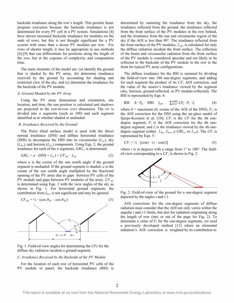
determined by summing the irradiance from the sky, the irradiance reflected from the ground, the irradiance reflected from the front surface of the PV modules in the row behind, and the irradiance from the sun and circumsolar region of the sky if the AOI is less than 90°. The irradiance reflected from the front surface of the PV modules, Irefl, is calculated for only the diffuse radiation incident the front surface. The reflection of the beam and circumsolar radiation from the front surface of the PV module is considered specular and not likely to be reflected to the backside of the PV module in the row to the front for typical PV array configurations.
The diffuse irradiance for the BSI is summed by dividing the field-of-view into 180 one-degree segments, and adding for each segment the product of its CF, AOI correction, and the value of the source’s irradiance viewed by the segment (sky, horizon, ground-reflected, or PV module-reflected). The BSI is represented by Eqn. 4:
BSI = 𝑏𝑏 ∙ 𝐹𝐹𝑏𝑏 ∙ (DNI + 𝐼𝐼𝑐𝑐𝑐𝑐𝑐𝑐) + ∑ 𝐶𝐶𝐹𝐹𝑐𝑐 ∙ 𝐹𝐹𝑐𝑐 ∙ 𝐼𝐼𝑐𝑐180°𝑐𝑐=1° (4)
where b = maximum (0, cosine of the AOI of the DNI); Fb is the AOI correction for the DNI using the air-glass model of Sjerps-Koomen et al. [10]; CFi is the CF for the ith one-degree segment; Fi is the AOI correction for the ith one-degree segment; and Ii is the irradiance viewed by the ith one-degree segment (either Isky, Ihor, ρ·GRIn, or Irefl). The CFi is represented by Eqn. 5:
CFi = ½ · [cos(i –1) – cos(i)] (5)
where i is in degrees with a range from 1° to 180°. The field-of-view corresponding to a CFi is shown in Fig. 2.
Fig. 2. Field-of-view of the ground for a one-degree segment depicted by the angles i and i-1.
AOI corrections for the one-degree segments of diffuse radiation must consider that the AOI not only varies within the angular i and i-1 limits, but also for radiation originating along the length of row (into or out of the page for Fig. 2). To determine a value of Fi for the one-degree segments, we used a previously developed method [11] where an elemental radiation’s AOI correction is weighted by its contribution to

3 This report is available at no cost from the National Renewable Energy Laboratory at www.nrel.gov/publications.
Fig. 3. AOI corrections for the one-degree segments of diffuse radiation as a function of the angle i. For PV modules with an uncoated glass back-surface with a refractive index of 1.526.
the in-plane irradiance. The results are shown in Fig. 3. Note that the Fi is always less than one because the majority of diffuse radiation is always directed other than normal to the surface.
Although variations in irradiance for the front side of the PV module are less, the same principles may be applied to account for inter-row shading and variations in field-of- view of the sky due to the presence of rows of other PV modules. For interior rows, the front side irradiance for the bottom of the PV module may be 1-2% less than for the top of the PV module. Backside irradiances have the opposite trend, with the irradiance for the bottom of the PV module being 2 or more times greater than for the top for some circumstances.
III. DATA
For comparison with the model estimates, the irradiances for the backsides of PV modules were measured using reference cells. The measurements were performed on NREL and Sandia National Laboratory PV systems.
A. NREL PV System
The previously installed NREL PV system is shown in Fig. 4. Subarrays are located on two roof levels and measurements were performed for both levels and near the center of the subarrays. The PV modules are monofacial and reference cells were used for short-term measurements of the available BSI. The reference cells were installed in the center of the subarray, parallel to the PV module back surface, and offset below to represent three locations along the slant-height of the PV module: bottom, middle, and top. A reference cell was also installed in the plane of the PV modules to measure the irradiance for the front side of the PV modules.
The PV modules are oriented with a tilt angle of 10° and an azimuth heading of 165°. Normalized by the PV module slant-height, the horizontal distance between rows is 0.56 and the
Fig. 4. PV system on the roof of NREL’s Science and Technology Facility building which was constructed in 2006.
vertical distance from the roof to the lower edge of the front surface of the PV module is 0.52.
The white roofing-membrane shows light/medium soiling and the average of the reflectivity measurements over the visible range is 55%. Consequently, an albedo 0.55 was used for modeling purposes. DNI and DHI values from NREL’s Solar Radiation Research Laboratory were also used for model input.
B. Sandia PV System
Sandia constructed a facility for testing bifacial PV modules in 2016. As shown in Fig. 5, it consists of four rows of PV modules with monofacial and bifacial PV modules alternating along a row’s length. Front to back, the rows are installed south-facing and with tilt angles of 15°, 25°, 35°, and 45°.
Normalized by the PV module slant-height (including the racking), the horizontal distance is 1.07 between the first and second row, 1.42 between the second and third row, and 1.8 between the third and fourth row; the vertical distance from the ground to the lower edge of the front surface of the PV module is 0.58. Compared to the NREL system, the distance between rows will provide more unshaded ground which increases the performance of bifacial PV modules.
For measuring the BSI, reference cells were installed near the middle of each row, parallel to the PV module back surface and offset below to represent two locations along the slant-height of the PV module: bottom and top. A reference cell was also installed in the plane of the PV modules on the east end of the row to measure the irradiance for the front side of the PV modules.
Albedo measurements of the crushed rock ground surface are performed with an inverted pyranometer and DNI and DHI measurements were performed at Sandia’s nearby meteorological station.
Data collection began in September 2016 and is ongoing. Other parameters related to the electrical performance of the PV modules are measured, but are not part of this study.

4 This report is available at no cost from the National Renewable Energy Laboratory at www.nrel.gov/publications.
Fig. 5. Bifacial PV module test bed at Sandia. Four rows of PV modules with tilt angles from 15° to 45°. Backside irradiance measured for top and bottom of PV module near the center of each row. Front side irradiances are also measured.
IV. RESULTS
A. NREL PV System
A comparison of the hourly measured and modeled BSI for the top, middle, and bottom reference cells are shown for a cloudy day in Fig. 6 and for a sunny day in Fig. 7 for the subarray on the lower roof of the building. The measured front side reference cell irradiances are included for reference.
While the model results for the cloudy day are favorable, the model underestimated the BSI for all reference cells by a significant amount for the sunny day. During a follow-up site visit on a sunny day, we observed considerable light being reflected to the roof under the subarray from the wall with windows located to the north. (Irradiance enhancements of this type are not addressed by the model.)
Fig. 6. Cloudy day modeled and measured irradiances for the top, middle, and bottom reference cells located on the backside of a middle row of PV modules of the subarray on the lower roof of the NREL building for November 22, 2016.
Fig. 7. Sunny day modeled and measured irradiances for the top, middle, and bottom reference cells located on the backside of a middle row of PV modules of the subarray on the lower roof of the NREL building for November 24, 2016.
To confirm our suspicions, the measurement equipment was moved to the middle of the subarray on the top roof to see if the absence of a wall with windows would improve the comparison between modeled and measured values.
For the measurement equipment installation on the top roof, Fig. 8 compares the measured and modeled BSI for the top, middle, and bottom reference cells for a sunny day. Model results are quite good, and they also duplicate the different diurnal profiles measured by the reference cells. Because the azimuth of the subarray is 15° east of south, shadows cast by the PV modules onto the roof have a different pattern in the morning than in the afternoon. This non-symmetry shifts the peak BSI values off-south, with a dependency on the location with respect to the PV module slant-height.
Fig. 8. Sunny day modeled and measured irradiances for the top, middle, and bottom reference cells located on the backside of a middle row of PV modules of the subarray on the upper roof of the NREL building for February 16, 2017.

5 This report is available at no cost from the National Renewable Energy Laboratory at www.nrel.gov/publications.
B. Sandia PV System
The continuous data collection at Sandia permitted statistics comparing modeled and measured BSIs to be determined for the 6-month period from October 1, 2016 through March 31, 2017 using available 15-minute data averages. The statistics used are the mean bias deviation (MBD) and the root-mean-square deviation (RMSD), with the results expressed in both W/m2 and as a percent of the mean of the measured values. The deviation is the measured value subtracted from the modeled value. For the MBD, a positive value indicates that the model overestimates on average.
The MBD and RMSD statistics for modeling the top and bottom BSIs are provided in Table 1. The MBDs were within ±9 W/m2 and ±16% and the RMSDs were less than 17 W/m2 and 32%. Because the BSI is added to the front side irradiance to determine the total irradiance for the PV cell, the statistics in units of W/m2 are more useful for evaluating the error in estimated cell output. The front side irradiances in Table 1 are generally a factor of 10 greater than the BSI. For additional context, comparing the measured GHI from the meteorological station with the measured GHI from the nearby bifacial module test bed yielded a MBD of 8.6 W/m2 and a RMSD of 11.7 W/m2, values not too different than those for the modeled BSIs.
Table 2 provides the MBDs and RMSDs for the modeled irradiance available to a bifacial PV cell, determined as the sum of the modeled front side irradiance and BSI, compared to the sum of the measured front side irradiance and BSI. The MBDs were within ±2.4% and the RMSDs were less than 6%. Fig. 9 is a scatterplot of the modeled front side irradiance plus the modeled BSI versus the measured front side irradiance plus the measured BSI for the top reference cell located on the backside of the row of PV modules with a tilt angle of 35°. The diagonal in the Fig. 9 has a slope of one, data points above the diagonal indicate model overestimates, and vice versa for data points below the diagonal. The figure shows good agreement between modeled and measured values.
The model did not consider shading by the concrete foundations or their location relative to the reference cells, and this may have adversely impacted the results, particularly for the bottom reference cells. Fig. 10 shows modeled and measured irradiances for the reference cells installed on the row with tilt angle of 15° for a clear day in March. While the model results for the top reference cell are good, the model doesn’t duplicate the shift in peak values of the bottom reference cell’s measured data toward the afternoon. This is thought to be a consequence of the reference cell being closer to the east concrete foundation than the west and reflections from the concrete foundations
Also shown in Fig. 10 are results when using the RADIANCE ray tracing software to model the irradiance for the top and bottom reference cells that includes the effects of the concrete foundations and the array structure. These results show a slight shift in peak values for the bottom reference cell
toward the afternoon, but not to the extent exhibited by the measured data.
Fig. 9. Scatterplot of the modeled bifacial irradiance (modeled front side irradiance plus the modeled BSI) versus the measured bifacial irradiance (measured front side irradiance plus the measured BSI) for the top reference cell located on the backside of the row of PV modules with a tilt angle of 35°.
Fig. 10. Modeled and measured irradiances for the top and bottom reference cells located on the backside of the row of PV modules with a tilt angle of 15° for March 1, 2017.
V. SUMMARY
A model was presented for estimating the BSI of a bifacial PV module applicable for a row or multiple rows of PV modules. For model efficiency, it calculates the BSI for each row of cells to quantify the radiation profile in the PV module slant height direction, but does not distinguish differences in backside irradiance along the row’s length. The model is based on the use of CFs to determine the fraction of a source of irradiance that is incident the PV module, and AOI correction factors are applied to account for both direct and diffuse radiation reflection losses from the front and back PV module surfaces.

6 This report is available at no cost from the National Renewable Energy Laboratory at www.nrel.gov/publications.
For PV systems installed at NREL and Sandia, the model estimates were in agreement with the measured BSIs, with the exception of results influenced by PV system features not addressed by the model. For the NREL system, the subarray on the lower roof received additional radiation reflected from the wall to the north. The concrete foundations at Sandia provided additional reflective surfaces and shadows.
The use of ray-tracing software such as RADIANCE is a useful tool for evaluating how the CF model results might be influenced by PV system features it doesn’t directly address.
ACKNOWLEDGEMENT
The U.S. Government retains and the publisher, by accepting the article for publication, acknowledges that the U.S. Government retains a nonexclusive, paid-up, irrevocable, worldwide license to publish or reproduce the published form of this work, or allow others to do so, for U.S. Government purposes.
REFERENCES
[1] R. Guerrero-Lemus, R. Vega, T. Kim, L. Shephard, “Bifacial solar photovoltaics – A technology review”, Renewable and Sustainable Energy Reviews 60: 1533-1549, 2016.
[2] R. Perez, P. Ineichen, R. Seals, J. Michalsky, “Modeling daylight availability and irradiance components from direct and global irradiances”, Solar Energy 44: 271-289, 1990.
[3] G. J. Ward, "The RADIANCE Lighting Simulation and Rendering System," Proceedings of the 21st Annual Conference on Computer Graphics and Interactive Techniques, ACM, 1994. Software at https://github.com/NREL/Radiance/releases
[4] C. Deline, S. MacAlpine, B. Marion, F. Toor, A. Asgharzadeh, J. Stein, “Assessment of Bifacial Photovoltaic Module Power Rating Methodologies – Inside and Out”, IEEE Journal of Photovoltaics, in press.
[5] M. Iqbal, An Introduction to Solar Radiation. Toronto: Academic Press Canada, 1983.
[6] A. Krenzinger, “Estimation of Radiation Incident on Bifacial Albedo-Collecting Panels”, Int. J. Solar Energy 4: 297-319, 1986.
[7] A. Lorenzo, G. Sala, S. Lopez-Romero, “Diffusing Reflectors for Bifacial Photovoltaic Panels”, Solar Cells 13: 277-292, 1985.
[8] U. Yusufoglu, T. Pletzer, L. Koduvelikulathu, C. Comparotto, R. Kopecek, H. Kurz, “Analysis of the Annual Performance of Bifacial Modules and Optimization Methods”, IEEE Journal of Photovoltaics 5: 320-328.
[9] J. Appelbaum, “Bifacial photovoltaic panels field”, Renewable Energy 85, 338-343, 2016.
[10] E. A. Sjerps-Koomen, E. A. Alsema, W. C. Turkenburg, “A simple model for PV module reflection losses under field conditions”, Solar Energy 57: 421–432, 1996.
[11] B. Marion, “Numerical method for angle-of-incidence correction factors for diffuse radiation incident photovoltaic modules”, Solar Energy 147: 344–348, 2017.
TABLE 1
MEAN BIAS DEVIATION (MBD) AND ROOT-MEAN-SQUARE DEVIATION (RMSD) FOR MODELED VALUES OF THE BSI FOR TOP AND BOTTOM REFERENCE CELL
LOCATIONS AND USING 15-MINUTE DATA MEASURED AT SANDIA FROM OCTOBER 1, 2016 THROUGH MARCH 31, 2017. AVERAGES BASED ON MEASURED VALUES.
PV Row/ Tilt Angle
Front Side Irradiance
Bottom BSI
Top BSI
Average (W/m2)
Average (W/m2)
MBD (W/m2)
MBD (%)
RMSD (W/m2)
RMSD (%)
Average (W/m2)
MBD (W/m2)
MBD (%)
RMSD (W/m2)
RMSD (%)
Row 1 / 15° 512 63.3 8.9 14.1 16.5 26.0 31.6 5.1 16.0 9.9 31.3 Row 2 / 25° 566 49.2 3.9 7.9 14.0 28.4 34.7 -1.0 -3.0 4.8 13.8 Row 3 / 35° 598 55.4 -1.3 -2.3 13.0 23.5 40.9 -3.7 -9.2 6.5 15.9 Row 4 / 45° 596 61.0 8.6 14.1 13.2 21.6 52.8 6.7 12.7 9.5 18.0
TABLE 2
MEAN BIAS DEVIATION (MBD) AND ROOT-MEAN-SQUARE DEVIATION (RMSD) FOR THE SUMS OF THE MODELED VALUES OF THE BSI FOR TOP AND BOTTOM
REFERENCE CELL LOCATIONS AND THE FRONT SIDE IRRADIANCE AND USING 15-MINUTE DATA MEASURED AT SANDIA FROM OCTOBER 1, 2016 THROUGH MARCH
31, 2017. AVERAGES BASED ON THE SUMS OF THE MEASURED VALUES.
PV Row/ Tilt Angle
Bottom BSI + Front Side Irradiance Top BSI + Front Side Irradiance
Average (W/m2)
MBD (W/m2)
MBD (%)
RMSD (W/m2)
RMSD (%)
Average (W/m2)
MBD (W/m2)
MBD (%)
RMSD (W/m2)
RMSD (%)
Row 1 / 15° 575 13.6 2.4 32.9 5.7 542 9.6 1.8 24.0 4.4 Row 2 / 25° 616 7.6 1.2 35.5 5.8 594 2.7 0.5 25.3 4.3 Row 3 / 35° 653 -8.6 -1.3 33.4 5.1 625 -11.1 -1.8 25.8 4.1 Row 4 / 45° 657 7.1 1.1 27.6 4.2 644 5.2 0.8 28.0 4.3
Related Documents


