www.ab.com/safety MACHINE SAFETY GUIDE A PRACTICAL GUIDE TO MACHINE SAFETY APPLICATION, LEGISLATION AND STANDARDS

A Practical Guide to Machine Safety Application
Oct 29, 2014
Welcome message from author
This document is posted to help you gain knowledge. Please leave a comment to let me know what you think about it! Share it to your friends and learn new things together.
Transcript
www.ab.com/safety
MACHINE SAFETY GUIDEA PRACTICAL GUIDE TO MACHINE SAFETY APPLICATION,LEGISLATION AND STANDARDS

Principles, Standards and Implementation
Table of Contents
1-1Visit our website: www.ab.com/catalogs
Regulations
Standards
Safety Strategy
ISO (International Organization for Standardization) . . . . . . . . . . . . 1-IEC (International Electrotechnical Commission) . . . . . . . . . . . . . . 1-EN Harmonized European Standards . . . . . . . . . . . . . . . . . . . . . . . 1-ISO and EN Standards (Type A) . . . . . . . . . . . . . . . . . . . . . . . . . . . 1-ISO and EN Standards (Type B) . . . . . . . . . . . . . . . . . . . . . . . . . . . 1-ISO and EN Standards (Type C) . . . . . . . . . . . . . . . . . . . . . . . . . . . 1-IEC and EN Standards . . . . . . . . . . . . . . . . . . . . . . . . . . . . . . . . . . . 1-U.S. Standards/OSHA Standards . . . . . . . . . . . . . . . . . . . . . . . . . . 1-ANSI Standards . . . . . . . . . . . . . . . . . . . . . . . . . . . . . . . . . . . . . . . . 1-National Fire Protection Association . . . . . . . . . . . . . . . . . . . . . . . . 1-Association for Manufacturing Technology . . . . . . . . . . . . . . . . . . . 1-Packaging Machinery Manufacturer’s Institute . . . . . . . . . . . . . . . . 1-American Society of Safety Engineers . . . . . . . . . . . . . . . . . . . . . . 1-Society of Plastics Industry . . . . . . . . . . . . . . . . . . . . . . . . . . . . . . . 1-Canada Standards . . . . . . . . . . . . . . . . . . . . . . . . . . . . . . . . . . . . . . 1-Australia Standards . . . . . . . . . . . . . . . . . . . . . . . . . . . . . . . . . . . . . 1-
Risk Assessment . . . . . . . . . . . . . . . . . . . . . . . . . . . . . . . . . . . . . . . 1-Machine Limit Determination . . . . . . . . . . . . . . . . . . . . . . . . . . . . . . 1-Task and Hazard Identification . . . . . . . . . . . . . . . . . . . . . . . . . . . . 1-Risk Estimation . . . . . . . . . . . . . . . . . . . . . . . . . . . . . . . . . . . . . . . . 1-Risk Reduction . . . . . . . . . . . . . . . . . . . . . . . . . . . . . . . . . . . . . . . . 1-Hierarchy of Measures for Risk Reduction . . . . . . . . . . . . . . . . . . . 1-Inherently Safe Design . . . . . . . . . . . . . . . . . . . . . . . . . . . . . . . . . . . 1-Protective Systems and Measures . . . . . . . . . . . . . . . . . . . . . . . . . 1-Evaluation . . . . . . . . . . . . . . . . . . . . . . . . . . . . . . . . . . . . . . . . . . . . 1-Training, Personal Protective Equipment . . . . . . . . . . . . . . . . . . . . 1-Standards . . . . . . . . . . . . . . . . . . . . . . . . . . . . . . . . . . . . . . . . . . . . 1-
EU Directive and Legislation . . . . . . . . . . . . . . . . . . . . . . . . . . . . . . 1-The Machinery Directive . . . . . . . . . . . . . . . . . . . . . . . . . . . . . . . . . 1-Essential Health and Safety Requirements . . . . . . . . . . . . . . . . . . . 1-Conformity Assessment . . . . . . . . . . . . . . . . . . . . . . . . . . . . . . . . . 1-Technical File . . . . . . . . . . . . . . . . . . . . . . . . . . . . . . . . . . . . . . . . . . 1-Conformity Assessment for Annex IV Machines . . . . . . . . . . . . . . . 1-Notified Bodies . . . . . . . . . . . . . . . . . . . . . . . . . . . . . . . . . . . . . . . . 1-EC Type Examination . . . . . . . . . . . . . . . . . . . . . . . . . . . . . . . . . . . . 1-EC Declaration of Conformity Procedure . . . . . . . . . . . . . . . . . . . . 1-EC Declaration of Incorporation . . . . . . . . . . . . . . . . . . . . . . . . . . . 1-The Use of Work Equipment Directive . . . . . . . . . . . . . . . . . . . . . . 1-US Regulations . . . . . . . . . . . . . . . . . . . . . . . . . . . . . . . . . . . . . . . . 1-Occupational Safety and Health Administration . . . . . . . . . . . . . . . 1-Canada Regulations . . . . . . . . . . . . . . . . . . . . . . . . . . . . . . . . . . . . 1-
Safety PrinciplesProtective Measures and Complementary Equipment
Safety Distance Calculation
Formula . . . . . . . . . . . . . . . . . . . . . . . . . . . . . . . . . . . . . . . . . . . . . . 1-Directions of Approach . . . . . . . . . . . . . . . . . . . . . . . . . . . . . . . . . . 1-Speed Constant . . . . . . . . . . . . . . . . . . . . . . . . . . . . . . . . . . . . . . . . 1-Stopping Time . . . . . . . . . . . . . . . . . . . . . . . . . . . . . . . . . . . . . . . . . 1-Depth Penetration Factors . . . . . . . . . . . . . . . . . . . . . . . . . . . . . . . 1-Reach Through Applications . . . . . . . . . . . . . . . . . . . . . . . . . . . . . . 1-Single or Multiple Beams . . . . . . . . . . . . . . . . . . . . . . . . . . . . . . . . . 1-Distance Calculations . . . . . . . . . . . . . . . . . . . . . . . . . . . . . . . . . . . 1-Angled Approaches . . . . . . . . . . . . . . . . . . . . . . . . . . . . . . . . . . . . . 1-Safety Mats . . . . . . . . . . . . . . . . . . . . . . . . . . . . . . . . . . . . . . . . . . . 1-Examples . . . . . . . . . . . . . . . . . . . . . . . . . . . . . . . . . . . . . . . . . . . . . 1-
Prevention of Unexpected Power-Up
Lockout/Tagout . . . . . . . . . . . . . . . . . . . . . . . . . . . . . . . . . . . . . . . . 1-Safety Isolation Systems . . . . . . . . . . . . . . . . . . . . . . . . . . . . . . . . . 1-Load Disconnects . . . . . . . . . . . . . . . . . . . . . . . . . . . . . . . . . . . . . . 1-Trapped Key Systems . . . . . . . . . . . . . . . . . . . . . . . . . . . . . . . . . . . 1-Alternative Measures to Lockout . . . . . . . . . . . . . . . . . . . . . . . . . . . 1-
Structure of Safety Related Control Systems
Formula . . . . . . . . . . . . . . . . . . . . . . . . . . . . . . . . . . . . . . . . . . . . . . 1-Directions of Approach . . . . . . . . . . . . . . . . . . . . . . . . . . . . . . . . . . 1-Speed Constant . . . . . . . . . . . . . . . . . . . . . . . . . . . . . . . . . . . . . . . . 1-Stopping Time . . . . . . . . . . . . . . . . . . . . . . . . . . . . . . . . . . . . . . . . . 1-Depth Penetration Factors . . . . . . . . . . . . . . . . . . . . . . . . . . . . . . . 1-Reach Through Applications . . . . . . . . . . . . . . . . . . . . . . . . . . . . . . 1-Single or Multiple Beams . . . . . . . . . . . . . . . . . . . . . . . . . . . . . . . . . 1-Distance Calculations . . . . . . . . . . . . . . . . . . . . . . . . . . . . . . . . . . . 1-Angled Approaches . . . . . . . . . . . . . . . . . . . . . . . . . . . . . . . . . . . . . 1-Safety Mats . . . . . . . . . . . . . . . . . . . . . . . . . . . . . . . . . . . . . . . . . . . 1-Examples . . . . . . . . . . . . . . . . . . . . . . . . . . . . . . . . . . . . . . . . . . . . . 1-
Preventing Access . . . . . . . . . . . . . . . . . . . . . . . . . . . . . . . . . . . . . . 1-Detection Devices . . . . . . . . . . . . . . . . . . . . . . . . . . . . . . . . . . . . . . 1-Logic Devices . . . . . . . . . . . . . . . . . . . . . . . . . . . . . . . . . . . . . . . . . 1-Safety Networks . . . . . . . . . . . . . . . . . . . . . . . . . . . . . . . . . . . . . . . 1-Output Devices . . . . . . . . . . . . . . . . . . . . . . . . . . . . . . . . . . . . . . . . 1-Connection Systems . . . . . . . . . . . . . . . . . . . . . . . . . . . . . . . . . . . . 1-
Principles, Standards and Implementation
Regulations
1-2 Visit our website: www.ab.com/catalogs
EU Directives and Legislation
1. The Machinery Directive2. The Use of Work Equipment by Workers at Work Directive
These two Directives are directly related as the Essential Health andSafety Requirements (EHSRs) from the Machinery Directive can beused to confirm the safety of equipment in the Use of WorkEquipment Directive.
This section deals with aspects of both directives and it is stronglyrecommended that anyone concerned with the design, supply,purchase or use of industrial equipment within or into the EEA andalso certain other European countries should familiarize themselveswith their requirements. Most suppliers and users of machinery willsimply not be allowed to supply or operate machinery in thesecountries unless they conform to these directives.
There are other European Directives with relevance to industrialsafety. Most of them are fairly specialized in their application andare therefore left outside the scope of this section but it is importantto note that, where relevant, their requirements must also be met.Examples are: The Low Voltage Directive—The ATEX Directive.
The Machinery Directive
Essential Health & Safety Requirements
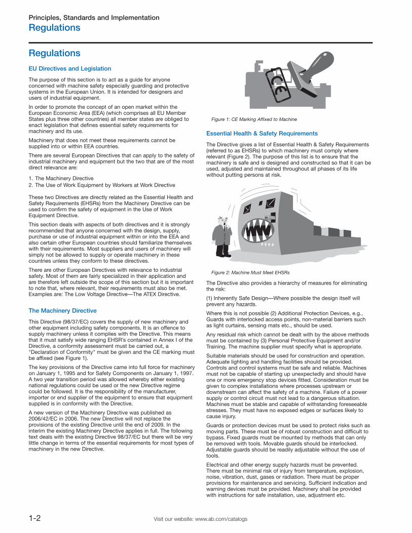
The Directive gives a list of Essential Health & Safety Requirements(referred to as EHSRs) to which machinery must comply whererelevant (Figure 2). The purpose of this list is to ensure that themachinery is safe and is designed and constructed so that it can beused, adjusted and maintained throughout all phases of its lifewithout putting persons at risk.
The Directive also provides a hierarchy of measures for eliminatingthe risk:
(1) Inherently Safe Design—Where possible the design itself willprevent any hazards.
Where this is not possible (2) Additional Protection Devices, e.g.,Guards with interlocked access points, non-material barriers suchas light curtains, sensing mats etc., should be used.
Any residual risk which cannot be dealt with by the above methodsmust be contained by (3) Personal Protective Equipment and/orTraining. The machine supplier must specify what is appropriate.
Suitable materials should be used for construction and operation.Adequate lighting and handling facilities should be provided.Controls and control systems must be safe and reliable. Machinesmust not be capable of starting up unexpectedly and should haveone or more emergency stop devices fitted. Consideration must begiven to complex installations where processes upstream ordownstream can affect the safety of a machine. Failure of a powersupply or control circuit must not lead to a dangerous situation.Machines must be stable and capable of withstanding foreseeablestresses. They must have no exposed edges or surfaces likely tocause injury.
Guards or protection devices must be used to protect risks such asmoving parts. These must be of robust construction and difficult tobypass. Fixed guards must be mounted by methods that can onlybe removed with tools. Movable guards should be interlocked.Adjustable guards should be readily adjustable without the use oftools.
Electrical and other energy supply hazards must be prevented.There must be minimal risk of injury from temperature, explosion,noise, vibration, dust, gases or radiation. There must be properprovisions for maintenance and servicing. Sufficient indication andwarning devices must be provided. Machinery shall be providedwith instructions for safe installation, use, adjustment etc.
Figure 1: CE Marking Affixed to Machine
Figure 2: Machine Must Meet EHSRs
Regulations
The purpose of this section is to act as a guide for anyoneconcerned with machine safety especially guarding and protectivesystems in the European Union. It is intended for designers andusers of industrial equipment.
In order to promote the concept of an open market within theEuropean Economic Area (EEA) (which comprises all EU MemberStates plus three other countries) all member states are obliged toenact legislation that defines essential safety requirements formachinery and its use.
Machinery that does not meet these requirements cannot besupplied into or within EEA countries.
There are several European Directives that can apply to the safety ofindustrial machinery and equipment but the two that are of the mostdirect relevance are:
This Directive (98/37/EC) covers the supply of new machinery andother equipment including safety components. It is an offence tosupply machinery unless it complies with the Directive. This meansthat it must satisfy wide ranging EHSR’s contained in Annex I of theDirective, a conformity assessment must be carried out, a"Declaration of Conformity" must be given and the CE marking mustbe affixed (see Figure 1).
The key provisions of the Directive came into full force for machineryon January 1, 1995 and for Safety Components on January 1, 1997.A two year transition period was allowed whereby either existingnational regulations could be used or the new Directive regimecould be followed. It is the responsibility of the manufacturer,importer or end supplier of the equipment to ensure that equipmentsupplied is in conformity with the Directive.
A new version of the Machinery Directive was published as2006/42/EC in 2006. The new Directive will not replace theprovisions of the existing Directive until the end of 2009. In theinterim the existing Machinery Directive applies in full. The followingtext deals with the existing Directive 98/37/EC but there will be verylittle change in terms of the essential requirements for most types ofmachinery in the new Directive.
Principles, Standards and Implementation
Regulations
1-3Visit our website: www.ab.com/catalogs
Conformity Assessment
Technical File
1. Overall drawings of the equipment including control circuitdrawings.
2. Detailed drawings, calculation notes, etc. required for checkingthe conformity of the machinery with the EHSRs.
3. A list of:
The EHSRs relevant to the equipment.Applicable Harmonized European Standards.Other applicable standards.Technical design specifications.
4. A description of methods adopted to eliminate hazards presentedby the machinery.
5. If desired, any technical report or certificate obtained from anapproved body (test house) or laboratory.
6. If conformity is declared with a Harmonized European Standard,any technical report giving test results for it.
7. A copy of the instructions for the machinery.
For series manufacture, details of internal measures (qualitysystems, for example) to ensure that all machinery producedremains in conformity:
The manufacturer must carry out necessary research or tests oncomponents, fittings or the completed machinery to determinewhether by its design and construction it is capable of beingerected and put into service safely.The technical file need not exist as a permanent single file, but itmust be possible to assemble it to make it available in areasonable time. It must be available for ten years followingproduction of the last unit. Failure to make it available inresponse to a substantiated request by an enforcement authoritymay constitute grounds for doubting the conformity.
The technical file does not need to include detailed plans or anyother specific information regarding sub-assemblies used for themanufacture of the machinery, unless they are essential to verifyconformity with the EHSRs.
Conformity Assessment for Annex IV Machines
Certain types of equipment are subject to special measures. Thisequipment is listed in Annex IV of the Directive and includesdangerous machines such as some woodworking machines,presses, injection molding machines, underground equipment,vehicle servicing lifts, etc.
Annex IV also includes certain safety components such as lightcurtains and two-hand control units.
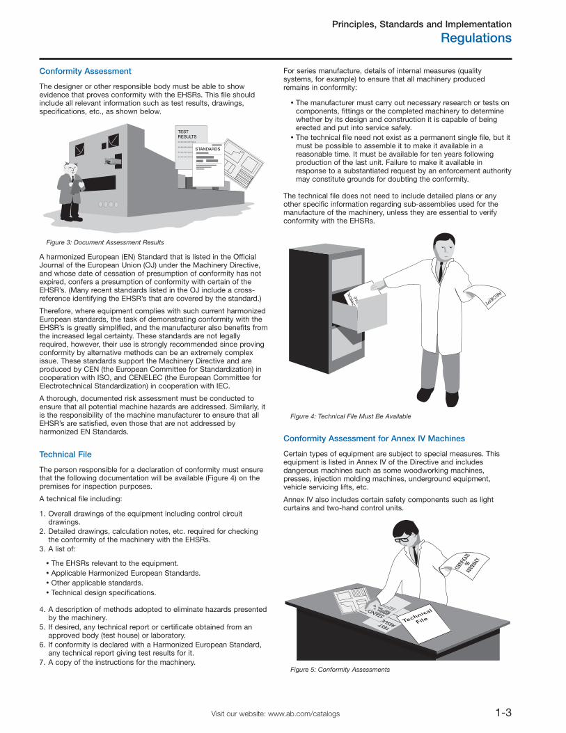
The person responsible for a declaration of conformity must ensurethat the following documentation will be available (Figure 4) on thepremises for inspection purposes.
A technical file including:
The designer or other responsible body must be able to showevidence that proves conformity with the EHSRs. This file shouldinclude all relevant information such as test results, drawings,specifications, etc., as shown below.
TEST RESULTS------------------------------------------------------------
STANDARDS
Figure 3: Document Assessment Results
Figure 4: Technical File Must Be Available
TEST RESULTS--------
----- ----------------STANDA
RDS
Technical
File
Figure 5: Conformity Assessments
A harmonized European (EN) Standard that is listed in the OfficialJournal of the European Union (OJ) under the Machinery Directive,and whose date of cessation of presumption of conformity has notexpired, confers a presumption of conformity with certain of theEHSR’s. (Many recent standards listed in the OJ include a cross-reference identifying the EHSR’s that are covered by the standard.)
Therefore, where equipment complies with such current harmonizedEuropean standards, the task of demonstrating conformity with theEHSR’s is greatly simplified, and the manufacturer also benefits fromthe increased legal certainty. These standards are not legallyrequired, however, their use is strongly recommended since provingconformity by alternative methods can be an extremely complexissue. These standards support the Machinery Directive and areproduced by CEN (the European Committee for Standardization) incooperation with ISO, and CENELEC (the European Committee forElectrotechnical Standardization) in cooperation with IEC.
A thorough, documented risk assessment must be conducted toensure that all potential machine hazards are addressed. Similarly, itis the responsibility of the machine manufacturer to ensure that allEHSR’s are satisfied, even those that are not addressed byharmonized EN Standards.
Principles, Standards and Implementation
Regulations
1-4 Visit our website: www.ab.com/catalogs
For Annex IV machines in conformity with Harmonized EuropeanStandards there are three procedures to choose from:
1. Send the technical file to a notified body that will acknowledgereceipt of the file and keep it.
2. Note: With this option there is no assessment of the file. It maybe used as reference at a later date in the event of a problem or aclaim of noncompliance.
3. Send the technical file to a notified body who will verify that theHarmonized Standards have been correctly applied and will issuea certificate of adequacy for the file.
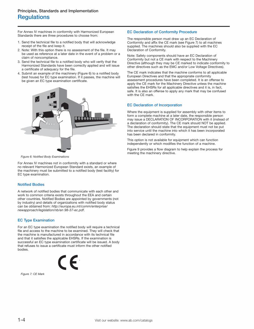
4. Submit an example of the machinery (Figure 6) to a notified body(test house) for EC type examination. If it passes, the machine willbe given an EC type examination certificate.
For Annex IV machines not in conformity with a standard or whereno relevant Harmonized European Standard exists, an example ofthe machinery must be submitted to a notified body (test facility) forEC type examination.
Notified Bodies
EC Type Examination
For an EC type examination the notified body will require a technicalfile and access to the machine to be examined. They will check thatthe machine is manufactured in accordance with its technical fileand that it satisfies the applicable EHSRs. If the examination issuccessful an EC type examination certificate will be issued. A bodythat refuses to issue a certificate must inform the other notifiedbodies.
EC Declaration of Conformity Procedure
The responsible person must draw up an EC Declaration ofConformity and affix the CE mark (see Figure 7) to all machinessupplied. The machines should also be supplied with the ECDeclaration of Conformity.
Note: Safety components should have an EC Declaration ofConformity but not a CE mark with respect to the MachineryDirective (although they may be CE marked to indicate conformity toother directives such as the EMC and/or Low Voltage Directives).
The CE mark indicates that the machine conforms to all applicableEuropean Directives and that the appropriate conformityassessment procedures have been completed. It is an offense toapply the CE mark for the Machinery Directive unless the machinesatisfies the EHSRs for all applicable directives and it is, in fact,safe. It is also an offense to apply any mark that may be confusedwith the CE mark.
EC Declaration of Incorporation
Where the equipment is supplied for assembly with other items toform a complete machine at a later date, the responsible personmay issue a DECLARATION OF INCORPORATION with it (instead ofa declaration of conformity). The CE mark should NOT be applied.The declaration should state that the equipment must not be putinto service until the machine into which it has been incorporatedhas been declared in conformity.
This option is not available for equipment which can functionindependently or which modifies the function of a machine.
Figure 9 provides a flow diagram to help explain the process formeeting the machinery directive.
Figure 6: Notified Body Examinations
Figure 7: CE Mark
A network of notified bodies that communicate with each other andwork to common criteria exists throughout the EEA and certainother countries. Notified Bodies are appointed by governments (notby industry) and details of organizations with notified body statuscan be obtained from: http://europa.eu.int/comm/enterprise/newapproach/legislation/nb/en 98-37-ec.pdf.
Principles, Standards and Implementation
Regulations
1-5Visit our website: www.ab.com/catalogs
The Use of Work Equipment Directive
Whereas the Machinery Directive is aimed at suppliers, this Directive(89/655/EEC as amended by 95/63/EC and 2001/45/EC) is aimed atusers of machinery. It covers all industrial sectors and it placesgeneral duties on employers together with minimum requirementsfor the safety of work equipment. All EEA countries are enactingtheir own forms of legislation to implement this Directive.
It is easier to understand the meaning of the requirements of theUse of Work Equipment Directive by looking at the example of itsimplementation into national legislation. We will look at itsimplementation in the UK under the name of The Provision and Useof Work Equipment Regulations (often abbreviated to P.U.W.E.R.).The form of implementation may vary between countries but theeffect of the Directive is retained.
Regulations 1 to 10
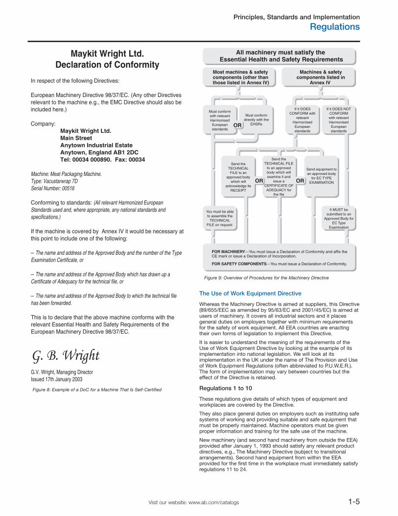
All machinery must satisfy the Essential Health and Safety Requirements
Most machines & safetycomponents (other thanthose listed in Annex IV)
Machines & safetycomponents listed in
Annex IV
Must conformwith relevantHarmonisedEuropeanstandards
Must conformdirectly with the
EHSRs
If it DOESCONFORM with
relevantHarmonisedEuropeanstandards
If it DOES NOTCONFORMwith relevantHarmonisedEuropeanstandards
OR
OR OR
Send theTECHNICALFILE to an
approved bodywhich will
acknowledge itsRECEIPT
Send theTECHNICAL FILE
to an approvedbody which willexamine it and
issue aCERTIFICATE OF
ADEQUACY forthe file
Send equipment toan approved body
for EC TYPEEXAMINATION
You must be ableto assemble the
TECHNICALFILE on request
It MUST besubmitted to an
Approved Body forEC Type
Examination
FOR MACHINERY—You must issue a Declaration of Conformity and affix theCE mark or issue a Declaration of Incorporation.
FOR SAFETY COMPONENTS—You must issue a Declaration of Conformity.
Figure 9: Overview of Procedures for the Machinery Directive
Maykit Wright Ltd.Declaration of Conformity
In respect of the following Directives:
European Machinery Directive 98/37/EC. (Any other Directives relevant to the machine e.g., the EMC Directive should also be included here.)
Company: Maykit Wright Ltd. Main Street Anytown Industrial Estate Anytown, England AB1 2DC Tel: 00034 000890. Fax: 00034
Machine: Meat Packaging Machine.Type: Vacustarwrap 7DSerial Number: 00516
Conforming to standards: (All relevant Harmonized European Standards used and, where appropriate, any national standards and specifications.)
If the machine is covered by Annex IV it would be necessary at this point to include one of the following:
– The name and address of the Approved Body and the number of the Type Examination Certificate, or
– The name and address of the Approved Body which has drawn up a Certificate of Adequacy for the technical file, or
– The name and address of the Approved Body to which the technical file has been forwarded.
This is to declare that the above machine conforms with the relevant Essential Health and Safety Requirements of the European Machinery Directive 98/37/EC.
G. B. WrightG.V. Wright, Managing DirectorIssued 17th January 2003
Figure 8: Example of a DoC for a Machine That Is Self-Certified
These regulations give details of which types of equipment andworkplaces are covered by the Directive.
They also place general duties on employers such as instituting safesystems of working and providing suitable and safe equipment thatmust be properly maintained. Machine operators must be givenproper information and training for the safe use of the machine.
New machinery (and second hand machinery from outside the EEA)provided after January 1, 1993 should satisfy any relevant productdirectives, e.g., The Machinery Directive (subject to transitionalarrangements). Second hand equipment from within the EEAprovided for the first time in the workplace must immediately satisfyregulations 11 to 24.
Principles, Standards and Implementation
Regulations
1-6 Visit our website: www.ab.com/catalogs
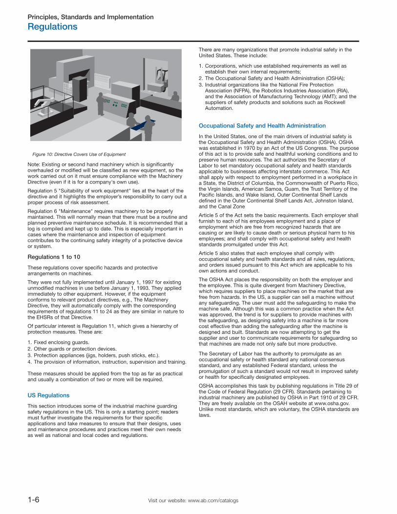
Note: Existing or second hand machinery which is significantlyoverhauled or modified will be classified as new equipment, so thework carried out on it must ensure compliance with the MachineryDirective (even if it is for a company's own use).
Regulation 5 "Suitability of work equipment" lies at the heart of thedirective and it highlights the employer’s responsibility to carry out aproper process of risk assessment.
Regulation 6 "Maintenance" requires machinery to be properlymaintained. This will normally mean that there must be a routine andplanned preventive maintenance schedule. It is recommended that alog is compiled and kept up to date. This is especially important incases where the maintenance and inspection of equipmentcontributes to the continuing safety integrity of a protective deviceor system.
Regulations 1 to 10
1. Fixed enclosing guards. 2. Other guards or protection devices. 3. Protection appliances (jigs, holders, push sticks, etc.). 4. The provision of information, instruction, supervision and training.
These measures should be applied from the top as far as practicaland usually a combination of two or more will be required.
US Regulations
There are many organizations that promote industrial safety in theUnited States. These include:
1. Corporations, which use established requirements as well asestablish their own internal requirements;
2. The Occupational Safety and Health Administration (OSHA); 3. Industrial organizations like the National Fire Protection
Association (NFPA), the Robotics Industries Association (RIA),and the Association of Manufacturing Technology (AMT); and thesuppliers of safety products and solutions such as RockwellAutomation.
Occupational Safety and Health Administration
The Secretary of Labor has the authority to promulgate as anoccupational safety or health standard any national consensusstandard, and any established Federal standard, unless thepromulgation of such a standard would not result in improved safetyor health for specifically designated employees.
OSHA accomplishes this task by publishing regulations in Title 29 ofthe Code of Federal Regulation (29 CFR). Standards pertaining toindustrial machinery are published by OSHA in Part 1910 of 29 CFR.They are freely available on the OSAH website at www.osha.gov.Unlike most standards, which are voluntary, the OSHA standards arelaws.
Figure 10: Directive Covers Use of Equipment
These regulations cover specific hazards and protectivearrangements on machines.
They were not fully implemented until January 1, 1997 for existingunmodified machines in use before January 1, 1993. They appliedimmediately to other equipment. However, if the equipmentconforms to relevant product directives, e.g., The MachineryDirective, they will automatically comply with the correspondingrequirements of regulations 11 to 24 as they are similar in nature tothe EHSRs of that Directive.
Of particular interest is Regulation 11, which gives a hierarchy ofprotection measures. These are:
This section introduces some of the industrial machine guardingsafety regulations in the US. This is only a starting point; readersmust further investigate the requirements for their specificapplications and take measures to ensure that their designs, usesand maintenance procedures and practices meet their own needsas well as national and local codes and regulations.
In the United States, one of the main drivers of industrial safety isthe Occupational Safety and Health Administration (OSHA). OSHAwas established in 1970 by an Act of the US Congress. The purposeof this act is to provide safe and healthful working conditions and topreserve human resources. The act authorizes the Secretary ofLabor to set mandatory occupational safety and health standardsapplicable to businesses affecting interstate commerce. This Actshall apply with respect to employment performed in a workplace ina State, the District of Columbia, the Commonwealth of Puerto Rico,the Virgin Islands, American Samoa, Guam, the Trust Territory of thePacific Islands, and Wake Island, Outer Continental Shelf Landsdefined in the Outer Continental Shelf Lands Act, Johnston Island,and the Canal Zone
Article 5 of the Act sets the basic requirements. Each employer shallfurnish to each of his employees employment and a place ofemployment which are free from recognized hazards that arecausing or are likely to cause death or serious physical harm to hisemployees; and shall comply with occupational safety and healthstandards promulgated under this Act.
Article 5 also states that each employee shall comply withoccupational safety and health standards and all rules, regulations,and orders issued pursuant to this Act which are applicable to hisown actions and conduct.
The OSHA Act places the responsibility on both the employer andthe employee. This is quite divergent from Machinery Directive,which requires suppliers to place machines on the market that arefree from hazards. In the US, a supplier can sell a machine withoutany safeguarding. The user must add the safeguarding to make themachine safe. Although this was a common practice when the Actwas approved, the trend is for suppliers to provide machines withthe safeguarding, as designing safety into a machine is far morecost effective than adding the safeguarding after the machine isdesigned and built. Standards are now attempting to get thesupplier and user to communicate requirements for safeguarding sothat machines are made not only safe but more productive.
Principles, Standards and Implementation
Regulations
1-7Visit our website: www.ab.com/catalogs
Some of the important parts as they pertain to machine safety areas follows:
The “point of operation” is the area on a machine where work isactually performed upon the material being processed. The point ofoperation of a machine, whose operation exposes an employee toinjury, shall be guarded. The guarding device shall be in conformitywith any appropriate standards or, in the absence of applicablespecific standards, shall be so designed and constructed as toprevent the operator from having any part of his body in the dangerzone during the operating cycle.
Subpart S (1910.399) states the OSHA electrical requirements. Aninstallation or equipment is acceptable to the Assistant Secretary ofLabor, and approved within the meaning of this Subpart S if it isaccepted, certified, listed, labeled, or otherwise determined to besafe by a nationally recognized testing laboratory (NRTL).
What is Equipment? A general term including material, fittings,devices, appliances, fixtures, apparatus, and the like, used as a partof, or in connection with, an electrical installation.
What is “Listed”? Equipment is "listed" if it is of a kind mentioned ina list which, (a) is published by a nationally recognized laboratorywhich makes periodic inspection of the production of suchequipment, and (b) states such equipment meets nationallyrecognized standards or has been tested and found safe for use in aspecified manner.
As of July 2006, the following companies are nationally recognizedtest labs:
Imminent DangerCatastrophes and FatalitiesEmployee ComplaintsHigh Hazardous IndustriesLocal Planned InspectionsFollow-up InspectionsNational and Local Focus Programs
A GeneralB Adoption and Extension of Established Federal StandardsC General Safety and Health ProvisionsH Hazardous MaterialsI Personal Protective EquipmentJ Environmental Controls⎯includes Lockout/Tagout
O Machinery and Machine GuardingR Special IndustriesS Electrical
Some OSHA standards reference voluntary standards. The legaleffect of incorporation by reference is that the material is treated asif it were published in full in the Federal Register. When a nationalconsensus standard is incorporated by reference in one of thesubparts, that standard is considered the law. For example, NFPA70, a voluntary standard known as the US National Electric Code, isreferenced in Subpart S. This makes the requirements in theNFPA70 standard mandatory.
29 CFR 1910.147, in Subpart J, covers the control of hazardousenergy. This is commonly known as the Lockout/Tagout standard.The equivalent voluntary standard is ANSI Z244.1. Essentially, thisstandard requires power to the machine to be locked out whenundergoing service or maintenance. The purpose is to prevent theunexpected energizing or startup of the machine which would resultin injury to employees.
Employers must establish a program and utilize procedures foraffixing appropriate lockout devices or tagout devices to energyisolating devices, and to otherwise disable machines or equipmentto prevent unexpected energizing, start up or release of storedenergy in order to prevent injury to employees.
Minor tool changes and adjustments, and other minor servicingactivities, which take place during normal production operations, arenot covered by this standard if they are routine, repetitive, andintegral to the use of the equipment for production, provided thatthe work is performed using alternative measures which provideeffective protection. Alternative measures are safeguarding deviceslike light curtains, safety mats, gate interlocks and other similardevices connected to a safety system. The challenge to themachine designer and user is to determine what is “minor” andwhat is “routine, repetitive and integral.”
Subpart O covers “Machinery and Machine Guarding.” This subpartlists the general requirements for all machines as well asrequirements for some specific machines. When OSHA was formedin 1970, it adopted many existing ANSI standards. For exampleB11.1 for mechanical power presses was adopted as 1910.217.
1910.212 is the general OSHA standard for machines. It states thatone or more methods of machine guarding shall be provided toprotect the operator and other employees in the machine area fromhazards such as those created by the point of operation, ingoing nippoints, rotating parts, flying chips and sparks. Guards shall beaffixed to the machine where possible and secured elsewhere if forany reason attachment to the machine is not possible. The guardshall be such that it does not offer an accident hazard itself.
Applied Research Laboratories, Inc. (ARL) Canadian Standards Association (CSA) Communication Certification Laboratory, Inc. (CCL) Curtis-Straus LLC (CSL) Electrical Reliability Services, Inc. (ERS) Entela, Inc. (ENT) FM Global Technologies LLC (FM) Intertek Testing Services NA, Inc. (ITSNA) MET Laboratories, Inc. (MET) NSF International (NSF) National Technical Systems, Inc. (NTS) SGS US Testing Company, Inc. (SGSUS) Southwest Research Institute (SWRI) TÜV America, Inc. (TÜVAM) TÜV Product Services GmbH (TÜVPSG) TÜV Rheinland of North America, Inc. (TÜV) Underwriters Laboratories Inc. (UL) Wyle Laboratories, Inc. (WL)
Some states have adopted their own local OSHAs. Twenty-fourstates, Puerto Rico and the Virgin Islands have OSHA-approvedState Plans and have adopted their own standards and enforcementpolicies. For the most part, these states adopt standards that areidentical to Federal OSHA. However, some states have adopteddifferent standards applicable to this topic or may have differentenforcement policies.
Employers must report incident history to OSHA. OSHA compilesincident rates and transmits the information to local offices, anduses this information to prioritize inspections. The key inspectiondrivers are:
Principles, Standards and Implementation
Regulations/Standards
1-8 Visit our website: www.ab.com/catalogs
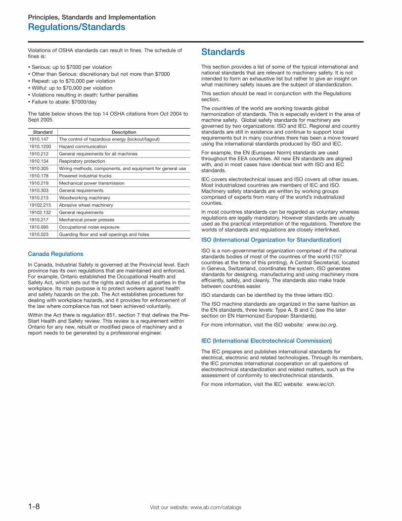
Violations of OSHA standards can result in fines. The schedule offines is:
Serious: up to $7000 per violationOther than Serious: discretionary but not more than $7000Repeat: up to $70,000 per violationWillful: up to $70,000 per violationViolations resulting in death: further penaltiesFailure to abate: $7000/day
The table below shows the top 14 OSHA citations from Oct 2004 toSept 2005.
Canada Regulations
In Canada, Industrial Safety is governed at the Provincial level. Eachprovince has its own regulations that are maintained and enforced.For example, Ontario established the Occupational Health andSafety Act, which sets out the rights and duties of all parties in theworkplace. Its main purpose is to protect workers against healthand safety hazards on the job. The Act establishes procedures fordealing with workplace hazards, and it provides for enforcement ofthe law where compliance has not been achieved voluntarily.
Within the Act there is regulation 851, section 7 that defines the Pre-Start Health and Safety review. This review is a requirement withinOntario for any new, rebuilt or modified piece of machinery and areport needs to be generated by a professional engineer.
ISO (International Organization for Standardization)
IEC (International Electrotechnical Commission)
This section provides a list of some of the typical international andnational standards that are relevant to machinery safety. It is notintended to form an exhaustive list but rather to give an insight onwhat machinery safety issues are the subject of standardization.
This section should be read in conjunction with the Regulationssection.
The countries of the world are working towards globalharmonization of standards. This is especially evident in the area ofmachine safety. Global safety standards for machinery aregoverned by two organizations: ISO and IEC. Regional and countrystandards are still in existence and continue to support localrequirements but in many countries there has been a move towardusing the international standards produced by ISO and IEC.
For example, the EN (European Norm) standards are usedthroughout the EEA countries. All new EN standards are alignedwith, and in most cases have identical text with ISO and IECstandards.
IEC covers electrotechnical issues and ISO covers all other issues.Most industrialized countries are members of IEC and ISO.Machinery safety standards are written by working groupscomprised of experts from many of the world’s industrializedcounties.
In most countries standards can be regarded as voluntary whereasregulations are legally mandatory. However standards are usuallyused as the practical interpretation of the regulations. Therefore theworlds of standards and regulations are closely interlinked.
Standards
Standard Description
1910.147 The control of hazardous energy (lockout/tagout)
1910.1200 Hazard communication
1910.212 General requirements for all machines
1910.134 Respiratory protection
1910.305 Wiring methods, components, and equipment for general use
1910.178 Powered industrial trucks
1910.219 Mechanical power transmission
1910.303 General requirements
1910.213 Woodworking machinery
19102.215 Abrasive wheel machinery
19102.132 General requirements
1910.217 Mechanical power presses
1910.095 Occupational noise exposure
1910.023 Guarding floor and wall openings and holes
ISO is a non-governmental organization comprised of the nationalstandards bodies of most of the countries of the world (157countries at the time of this printing). A Central Secretariat, locatedin Geneva, Switzerland, coordinates the system. ISO generatesstandards for designing, manufacturing and using machinery moreefficiently, safely, and cleanly. The standards also make tradebetween countries easier.
ISO standards can be identified by the three letters ISO.
The ISO machine standards are organized in the same fashion asthe EN standards, three levels: Type A, B and C (see the latersection on EN Harmonized European Standards).
For more information, visit the ISO website: www.iso.org.
The IEC prepares and publishes international standards forelectrical, electronic and related technologies. Through its members,the IEC promotes international cooperation on all questions ofelectrotechnical standardization and related matters, such as theassessment of conformity to electrotechnical standards.
For more information, visit the IEC website: www.iec/ch.
Principles, Standards and Implementation
Standards
1-9Visit our website: www.ab.com/catalogs
EN Harmonized European Standards
ISO and EN Standards (Type A)
EN ISO 12100
ISO 14121 (EN 1050)
Principles for risk assessment.
Outlines the fundamentals of assessing the risks during the life ofthe machinery. It summarizes methods for hazard analysis and riskestimation.
ISO and EN Standards (Type B)
ISO 11161 (will also be EN 11161)
ISO 13849 (EN 954)
Safety related parts of control systems—Pt 1: General principlesfor design. Pt 2: Validation
This standard outlines requirements for safety critical parts ofmachine control systems and describes 5 categories ofperformance "B, 1, 2, 3 and 4." It is important to gather a workingknowledge of this document as its categories are becomingaccepted as the common "language" for describing theperformance of safety related control systems.
ISO 13849-1:2006
ISO 13850 (EN 418)
Emergency Stop devices, functional aspects—Principles fordesign.
Provides design principles and requirements.
ISO 13851 (EN 574)
Two-hand control devices—Functional aspects—Principles fordesign.
Provides requirements and guidance on the design and selection oftwo-hand control devices, including the prevention of defeat and theavoidance of faults.
ISO 13852 (EN 294)
Safety distances to prevent danger zones being reached by theupper limbs.
Provides data for calculation of safe aperture sizes and positioningfor guards, etc.
ISO 13853 (EN 811)
Safety distances to prevent danger zones being reached by thelower limbs.
Provides data for calculation of safe aperture sizes and positioningfor guards, etc.
This standard underwent revision, and was published in late 2006. Itis published both as an EN and ISO version with the same number:13849-1. At the time of the printing of this catalog, it is expectedthat the current version of EN 954-1: 1996 will remain applicableprobably until the end of 2009 for the European Community. The2006 revision represents a significant change. It will introduce someaspects not considered in the current version. The term "PL"(Performance Level) is used to describe the level of integrity of asystem or a subsystem.
The revised standard will be an alternative to EN/IEC 62061 (seelater). It is intended to provide a more direct and simplemethodology but at the expense of some constraints andrestrictions. Either the revised ISO/EN 13849-1 or IEC/EN 62061 canbe applied to most machinery electrical safety related systems andthe user should choose whichever one is best suited to their needs.
These standards are common to all EEA countries and are producedby the European Standardization Organizations CEN and CENELEC.Their use is voluntary but designing and manufacturing equipmentto them is the most direct way of demonstrating compliance withthe EHSRs.
They are divided into 3 types: A, B and C standards.
Type A. STANDARDS: Cover aspects applicable to all types ofmachines.
Type B. STANDARDS: Subdivided into two groups.
Type B1 STANDARDS: Cover particular safety and ergonomicaspects of machinery.
Type B2 STANDARDS: Cover safety components and protectivedevices.
Type C. STANDARDS: Cover specific types or groups of machines.
It is important to note that complying with a C Standard givesautomatic presumption of conformity with the EHSRs. In theabsence of a suitable C Standard, A and B Standards can be usedas part or full proof of EHSR conformity by pointing to compliancewith relevant sections.
The solar system can be used to model the relationship of themachinery directive to the European standards. The planetsrepresent the standards, which revolve around the sun, whichrepresents the machinery directive. The inner orbits are the "A" and"B" standards. The outer orbits represent the "C" standards.
Agreements have been reached for cooperation betweenCEN/CENELEC and bodies such as ISO and IEC. This shouldultimately result in common worldwide standards. In most cases anEN Standard has a counterpart in IEC or ISO. In general the twotexts will be the same and any regional differences will be given inthe forward of the standard.
This section lists some of the EN/ISO/IEC and other National andRegional Standards relevant to Machinery Safety.
Where an EN standard is shown in brackets it is identical or veryclosely aligned with the ISO or IEC standard.
For a complete list of EN Machinery Safety standards go tohttp://europa.eu.int/comm/enterprise/mechan_equipment/machinery/index.htm.
Safety of machinery. Basic concepts, general principles fordesign. Pts 1 & 2
This is an A standard which outlines all the basic principlesincluding risk assessment, guarding, interlocking, emergency stops,trip devices, safety distances, etc. It references to other standardsthat provide greater levels of detail.
Safety of Integrated Manufacturing Systems—Basic Requirements.
This standard should be published in its revised form in 2007. Thisrevised version has been significantly updated making it very usefulfor contemporary integrated machinery.
Principles, Standards and Implementation
Standards
1-10 Visit our website: www.ab.com/catalogs
ISO 13854 (EN 349)
Minimum distances to avoid crushing parts of the human body.
Provides data for calculation of safe gaps between moving parts,etc.
ISO 13855 (EN 999)
The positioning of protective equipment in respect to approachspeeds of parts of the human body.
Provides methods for designers to calculate the minimum safetydistances from a hazard for specific safety devices, in particular forelectrosensitive devices (e.g., light curtains), pressure sensitivemats/floors and two-hand controls. It contains a principle for thepositioning of safety devices based on approach speed andmachine stopping time that can reasonably be extrapolated to coverinterlocked guard doors without guard locking.
ISO 13856-1 (EN 1760-1)
Pressure Sensitive Safety Devices—Pt 1: Mats & Floors.
Provides requirements and test procedures.
ISO 13856-2 (EN 1760-2)
Pressure Sensitive Safety Devices—Pt 2: Edges & Bars.
Provides requirements and test procedures
ISO 14118 (EN 1037)
Isolation and energy dissipation—Prevention of unexpectedstart-up.
Defines measures aimed at isolating machines from power suppliesand dissipating stored energy to prevent unexpected machinestartup and allow safe intervention in danger zones.
ISO 14119 (EN 1088)
Interlocking devices associated with guards—Principles fordesign and selection.
Provides principles for the design and selection of interlockingdevices associated with guards.
In order to verify mechanical switches it refers to IEC 60947-5-1—Low voltage switch gear—Pt 5: Control circuit devices andswitching elements—Section 1: Electromechanical control circuitdevices.
In order to verify non-mechanical switches it refers to IEC 60947-5-3—Particular requirements for proximity devices with definedbehavior under fault conditions.
ISO 14120 (EN 953)
General Requirements for the Design and Construction ofGuards.
Provides definitions, descriptions and design requirements for fixedand movable guards.
ISO and EN Standards (Type C)
There is a large range of Type C Standards that cover specific type’spf machinery. For example:
ISO 10218-1
Industrial robots
EN 415-4
Safety of packaging machines. Palletizers and depalletizers.
IEC and EN Standards
IEC/EN 60204-1
Electrical equipment of machines—Pt 1 General requirements.
This is a very important standard that outlines recommendations forsafety related aspects of wiring and electrical equipment onmachines. A significantly revised version was published in 2006.This revision removed the former preference for electromechanicalsafety circuits.
IEC/EN 61508
Functional safety of electrical, electronic and programmableelectronic safety-related systems.
This standard is important because it contains the requirements andprovisions that are necessary for the design of complex electronicand programmable systems and subsystems. The standard isgeneric so it is not restricted to the machinery sector. It is a lengthyand complex document comprising seven parts. Within themachinery sector, its use is mostly for the design of complexdevices such as safety PLCs. For system level design andintegration aspects for machinery the sector specific standards suchas IEC/EN 62061 or the revised version of ISO/EN 13849-1 areprobably the most suitable. IEC 61508 has mapped out theapproach for a new generation of sector and product specificstandards that are now emerging. It introduced the term SIL (safetyintegrity level) and gives a hierarchy of 4 SILs which are applied to asafety function. SIL 1 is the lowest and SIL 4 is the highest. SIL 4 isnot usually applicable to the machinery sector because it isintended to be related to very high risk levels more associated withsectors such as petrochemical or nuclear.
IEC/EN 62061
Functional safety of safety related electrical, electronic andprogrammable electronic control systems.
This standard is one of the new generations of standards that usethe term SIL (safety integrity level). It is the machinery specificimplementation of IEC/EN 61508. It specifies requirements andmakes recommendations for the design, integration and validationof electrical safety related control systems for machines. Thisstandard provides an alternative approach to the existing EN 954-1and is intended to be useful for the increasingly complex safetyfunctionality required for today’s current and future machinery Forless complex safety functionality the revised version of ISO/EN13849-1 may be easier to implement. The use of these standardsrequires the availability of data such as PFHd (probability ofdangerous failure per hour) or MTTFd (mean time to dangerousfailure). The derivation of this data will be considered later in thissection.
Principles, Standards and Implementation
Standards
1-11Visit our website: www.ab.com/catalogs
IEC/EN 61496
Electro-sensitive protective equipment Pt 1: Generalrequirements and tests.
General requirements and tests.
Pt 2: Particular requirements for equipment using activeoptoelectronic protective devices.
Part 1 gives requirements and test procedures for the control andmonitoring aspects for electrosensitive protective equipment.Subsequent parts deal with aspects particular to the sensing side ofthe system. Part 2 gives particular requirements for safety lightcurtains.
Draft IEC 61800-5-2
Functional safety of power drive systems.
This standard will deal with drives that have safety functionality.
US Standards
Where possible, OSHA promulgates national consensus standardsor established Federal standards as safety standards. Themandatory provisions (e.g., the word shall implies mandatory) of thestandards, incorporated by reference, have the same force andeffects as the standards listed in Part 1910. For example, thenational consensus standard NFPA 70 is listed as a referencedocument in Appendix A of Subpart S-Electrical of Part 1910 of 29CFR. NFPA 70 is a voluntary standard, which was developed by theNational Fire Protection Association (NFPA). NFPA 70 is also knownas the National Electric Code (NEC). By incorporation, all themandatory requirements in the NEC are mandatory by OSHA.
The following is a list of some of the OSHA standards relevant tomachinery safety:
1910 Subpart O—Machinery and Machine Guarding
1910.211—Definitions.
1910.212—General requirements for all machines.
1910.213—Woodworking machinery requirements.
1910.214—Cooperage machinery. [Reserved]
1910.215—Abrasive wheel machinery.
1910.216—Mills and calendars in the rubber and plastics industries.
1910.217—Mechanical power presses.
1910.217 App A—Mandatory requirements forcertification/validation of safety systems for presence sensingdevice initiation of mechanical power presses
1910.217 App B—Nonmandatory guidelines forcertification/validation of safety systems for presence sensingdevice initiation of mechanical power presses
1910.217 App C—Mandatory requirements for OSHA recognition ofthird-party validation organizations for the PSDI standard
1910.217 App D—Nonmandatory supplementary information
1910.218—Forging machines.
1910.219—Mechanical power
1910.255—Resistance welding.
1910 Subpart R—Special Industries
1910.261—Pulp, paper, and paperboard mills.
1910.262—Textiles.
1910.263—Bakery equipment.
1910.264—Laundry machinery and operations.
1910.265—Sawmills.
1910.266—Logging operations.
The American National Standards Institute (ANSI) serves as theadministrator and coordinator of the United States private sectorvoluntary standardization system. It is a private, non profit,membership organization supported by a diverse constituency ofprivate and public sector organizations.
ANSI, itself, does not develop standards; it facilitates thedevelopment of standards by establishing consensus amongqualified groups. ANSI also ensures that the guiding principles ofconsensus, due process and openness are followed by the qualifiedgroups. Below is a partial list of industrial safety standards that canbe obtained by contacting ANSI.
These standards are categorized as either application standards orconstruction standards. Application standards define how to apply asafeguarding to machinery. Examples include ANSI B11.1, whichprovides information on the use of machine guarding on powerpresses, and ANSI/RIA R15.06, which outlines safeguarding use forrobot guarding.
The National Fire Protection Association (NFPA) was organized in1896. Its mission is to reduce the burden of fire on the quality of lifeby advocating scientifically based consensus codes and standards,research and education for fire and related safety issues. The NFPAsponsors many standards to help accomplish its mission. Two veryimportant standards related to industrial safety and safe-guardingare the National Electric Code (NEC) and Electrical Standard forIndustrial Machinery.
The National Fire Protection Association has acted as sponsor ofthe NEC since 1911. The original code document was developed in1897 as a result of the united efforts of various insurance, electrical,architectural, and allied interests. The NEC has since been updatednumerous times; it is revised about every three years. Article 670 ofthe NEC covers some details on industrial machinery and refers thereader to the Electrical Standard for Industrial Machinery, NFPA 79.
NFPA 79 applies to electrical/electronic equipment, apparatus, orsystems of industrial machines operating from a nominal voltage of600 volts or less. The purpose of NFPA 79 is to provide detailedinformation for the application of electrical/electronic equipment,apparatus, or systems supplied as part of industrial machines thatwill promote safety to life and property. NFPA 79, which wasofficially adopted by ANSI in 1962, is very similar in content to thestandard IEC 60204-1.
Machines, which are not covered by specific OSHA standards, arerequired to be free of recognized hazards which may cause death orserious injuries. These machines must be designed and maintainedto meet or exceed the requirements of applicable industrystandards. NFPA 79 is a standard that would apply to machines notspecifically covered by OSHA standards.
ANSI/NFPA 70
U.S. National Electrical Code
ANSI/NFPA 70E
Electrical Safety Requirements for Employee Workplaces
ANSI/NFPA 79
Electrical Standard for Industrial Machinery
OSHA Standards
ANSI Standards
National Fire Protection Association

Principles, Standards and Implementation
Standards
1-12 Visit our website: www.ab.com/catalogs
ANSI B11.1
Machine Tools - Mechanical Power Presses - Safety Requirementsfor Construction, Care, and Use
ANSI B11.2
Machine Tools - Hydraulic Power Presses, Safety Requirements forConstruction, Care, and Use
ANSI B11.3
Power Press Brakes, Safety Requirements for the Construction,Care, and Use
ANSI B11.4
Machine Tools - Shears - Safety Requirements for Construction,Care, and Use
ANSI B11.5
Machine Tools - Iron Workers - Safety Requirements forConstruction, Care, and Use
ANSI B11.6
Lathes, Safety Requirements for the Construction, Care, and Use
ANSI B11.7
Machine Tools - Cold Headers and Cold Formers, SafetyRequirements for Construction, Care, and Use
ANSI B11.8
Drilling, Milling, and Boring Machines, Safety Requirements for theConstruction, Care, and Use
ANSI B11.9
Grinding Machines, Safety Requirements for the Construction, Care,and Use
ANSI B11.10
Metal Sawing Machines, Safety Requirements for Construction,Care, and Use
ANSI B11.11
Gear Cutting Machines, Safety Requirements for the Construction,Care, and Use
ANSI B11.12
Machine Tools - Roll-Forming and Roll-Bending Machines - SafetyRequirements for the Construction, Care, and Use
ANSI B11.13
Machine Tools - Single- and Multiple-Spindle Automatic Bar andChucking Machines - Safety Requirements for Construction, Careand Use
ANSI B11.14
Machine Tools - Coil-Slitting Machines Safety Requirements forConstruction, Care, and Use – Withdrawn and rolled into B11.18
ANSI B11.15
Pipe, Tube, and Shape Bending Machines, Safety Requirements forConstruction, Care, and Use
ANSI B11.16
Metal Powder Compacting Presses, Safety Requirements forConstruction, Care, and Use
ANSI B11.17
Machine Tools - Horizontal Hydraulic Extrusion Presses - SafetyRequirements for Construction, Care, and Use
ANSI B11.18
Machine Tools - Machines and Machinery Systems for ProcessingStrip, Sheet, or Plate from Coiled Configuration - SafetyRequirements for Construction, Care, and Use
ANSI B11.19
Machine Tools - Safeguarding When Referenced by Other B11Machine Tool Safety Standards-Performance Criteria for the Design,Construction, Care and Operation
ANSI B11.20
Machine Tools - Manufacturing Systems/Cells – SafetyRequirements for Construction, Care, and Use
ANSI B11.21
Machine Tools - Machine Tools Using Lasers for ProcessingMaterials - Safety Requirements for Design, Construction, Care, andUse
ANSI B11.TR3
Risk assessment and risk reduction – A guide to estimate, evaluateand reduce risks associated with machine tools
ANSI B11.TR4
This technical report covers the application of programmablecontrollers to safety applications.
ANSI B11.TR6
This technical report, currently in development, will provide circuitexamples of safety functions to accommodate various levels of riskReduction.
ANSI ISO 12100
Safety of machinery. Basic concepts, general principles for design.Pts -1 and -2
The standard ISO 12100 has been adopted in the US by AMT as anidentical ANSI standard. ISO 12100 is a globally applicable top levelbasic principles standard that forms the framework for most of theISO, IEC and EN machinery safety standards. It provides a riskassessment approach as opposed to a prescriptive and restrictiveapproach. The aim is to avoid cost and trade barrier problemscaused by a multiplicity of different national standards covering thesame subject in different ways.
Robot Industries Association
ANSI RIA R15.06
Safety Requirements for Industrial Robots and Robot Systems
Association for Manufacturing Technology
Principles, Standards and Implementation
Standards
1-13Visit our website: www.ab.com/catalogs
Australia Standards
Packaging Machinery Manufacturer’s Institute
ANSI PMMI B155.1
Safety Requirements for Packaging Machinery and Packaging-Related Converting Machinery
The packaging standard was recently revised to incorporate riskassessment and risk reduction.
American Society of Safety Engineers
Z224.1
Control of Hazardous Energy, Lockout/Tag out and AlternativeMethods
This standard is similar to OSHA 1910.147. It provides a method(risk assessment) to determine the appropriate alternative methodwhen energy cannot be locked out.
Society of Plastics Industry
ANSI B151.1
Horizontal Injection Molding Machines – Safety Requirements forManufacture, Care and Use
ANSI B151.15
Extrusion Blow Molding Machines – Safety Requirements
ANSI B151.21
Injection Blow Molding Machines - Safety Requirements
ANSI B151.26
Plastics Machinery - Dynamic Reaction - Injection MoldingMachines - Safety Requirements for the Manufacture, Care and Use
ANSI B151.27
Plastics Machinery - Robots used with Horizontal Injection MoldingMachines - Safety Requirements for the Integration, Care and Use
ANSI B151.28
Plastics Machinery - Machines to Cut, Slit, of Buff Plastic Foams -Safety Requirements for the Manufacture, Care and Use
Canada Standards
CSA Standards reflect a national consensus of producers andusers⎯including manufactures, consumers, retailers, unions andprofessional organizations, and government agencies. Thestandards are used widely by industry and commerce and oftenadopted by municipal, provincial, and federal governments in theirregulations, particularly in the fields of health, safety, building andconstruction, and the environment.
Individuals, companies, and associations across Canada indicatetheir support for CSA’s standards development by volunteering theirtime and skills to CSA Committee work and supporting theAssociation’s objectives through sustaining memberships. Themore than 7000 committee volunteers and the 2000 sustainingmemberships together form CSA’s total membership.
The Standards Council of Canada is the coordinating body of theNational Standards system, a federation of independent,autonomous organizations working towards the further developmentand improvement of voluntary standardization in the nationalinterest.
CSA Z432-04
Safeguarding of Machinery
CSA Z434-03
Industrial Robots and Robot Systems - General SafetyRequirements
CSA Z460-05
Control of hazardous energy – Lockout and other methods
CSA Z142-02
Code for Power Press Operation: Health, Safety, and GuardingRequirements
Most of these standards are closely aligned with the equivalentISO/IEC/EN standards
Standards Australia Limited286 Sussex Street,Sydney,NSW 2001Phone: +61 2 8206 6000Email: [email protected]: www.standards.org.au
To purchase copies of standards:
SAI Global Limited286 Sussex StreetSydneyNSW 2001Phone: +61 2 8206 6000Fax: +61 2 8206 6001Email: [email protected]: www.saiglobal.com/shop
Principles, Standards and Implementation
Standards
1-14 Visit our website: www.ab.com/catalogs
AS 4024.1-2006
Safeguarding of machinery. Part 1: General principles
AS 4024.1101-2006 Terminology – General
AS 4024.1201-2006 Basic terminology and methodology
AS 4024.1202-2006 Technical principles
AS 4024.1301-2006 Principles of risk assessment
AS 4024.1302-2006 Reduction of risks to health and safety fromhazardous substances emitted by machinery
AS 4024.1401-2006 Design principles – Terminology and generalprinciples
AS 4024.1501-2006 Design of safety related parts of controlsystems – General principles
AS 4024.1502-2006 Design of safety related parts of controlsystems – Validation
AS 4024.1601-2006 General requirements for the design andconstruction of fixed and movable guards
AS 4024.1602-2006 Principles for the design and selection ofinterlocks
AS 4024.1603-2006 Prevention of unexpected start-up
AS 4024.1604-2006 Emergency stop – Principles for design
AS 4024.1701-2006 Basic human body measurements fortechnological design
AS 4024.1702-2006 Principles for determining the dimensionsrequired for openings for whole body access to machinery
AS 4024.1703-2006 Principles for determining the dimensionsrequired for access openings
AS 4024.1704-2006 Anthropometric data
AS 4024.1801-2006 Safety distances – Upper limbs
AS 4024.1802-2006 Safety distances – Lower limbs
AS 4024.1803-2006 Minimum gaps to prevent crushing of parts ofthe human body
AS 4024.1901-2006 General principles for human interaction withdisplays and control actuators
AS 4024.1902-2006 Displays
AS 4024.1903-2006 Control actuators
AS 4024.1904-2006 Requirements for visual, auditory and tactilesigns
AS 4024.1905-2006 Requirements for marking
AS 4024.1906-2006 Requirements for the location and operation ofactuators
AS 4024.1907-2006 System of auditory and visual danger andinformation signals
AS4024.2-1998
Safeguarding of machinery. Part 2: Installation and commissioningrequirements for electro-sensitive systems—Optoelectronic devices
The basis of this standard is IEC 61496-1 and -2. Part 2 covers theinstallation and commissioning of light curtains specifically relatedto machinery safety.
AS 4024.3-1998
Safeguarding of machinery. Part 3: Manufacturing and testingrequirements for electro-sensitive systems— Optoelectronic devices
The basis of this standard is IEC 61496-1 and -2. Part 3 covers themanufacturing and testing of light curtains specifically related tomachinery safety.
AS4024.4-1998
Safeguarding of machinery. Part 4: Installation and commissioningrequirements for electro-sensitive systems—Pressure-sensitivedevices
The basis of this standard is EN 1760-1 and EN 1760-2. Part 4covers the installation and commissioning of mats, floors, edgesand bars that are used with machinery, regardless of the energyused.
AS 4024.5-1998
Safeguarding of machinery. Part 5: Manufacturing and testingrequirements for electro-sensitive systems— Pressure-sensitivedevices
The basis of this standard is EN1760-1 and EN1760-2. Part 5covers the manufacturing and testing mats, floors, edges and barsthat are used with machinery, regardless of the energy used.
Principles, Standards and Implementation
Safety Strategy
1-15Visit our website: www.ab.com/catalogs
Safety Strategy
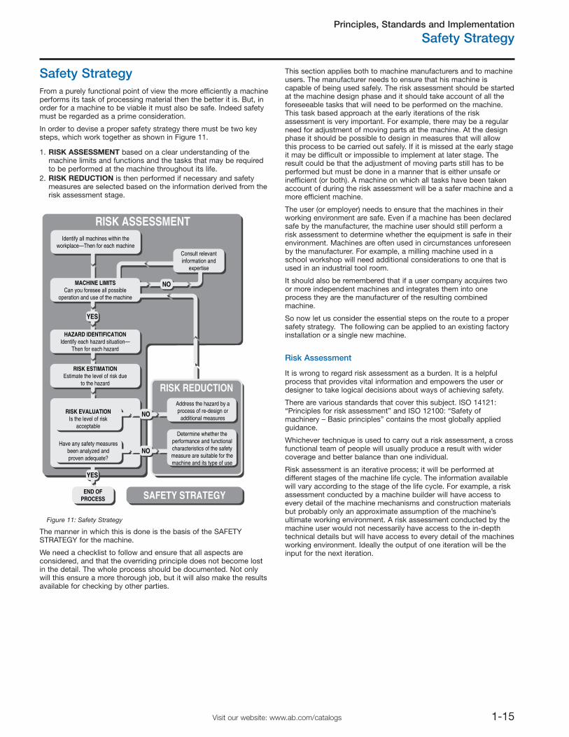
1. RISK ASSESSMENT based on a clear understanding of themachine limits and functions and the tasks that may be requiredto be performed at the machine throughout its life.
2. RISK REDUCTION is then performed if necessary and safetymeasures are selected based on the information derived from therisk assessment stage.
Risk Assessment
From a purely functional point of view the more efficiently a machineperforms its task of processing material then the better it is. But, inorder for a machine to be viable it must also be safe. Indeed safetymust be regarded as a prime consideration.
In order to devise a proper safety strategy there must be two keysteps, which work together as shown in Figure 11.
This section applies both to machine manufacturers and to machineusers. The manufacturer needs to ensure that his machine iscapable of being used safely. The risk assessment should be startedat the machine design phase and it should take account of all theforeseeable tasks that will need to be performed on the machine.This task based approach at the early iterations of the riskassessment is very important. For example, there may be a regularneed for adjustment of moving parts at the machine. At the designphase it should be possible to design in measures that will allowthis process to be carried out safely. If it is missed at the early stageit may be difficult or impossible to implement at later stage. Theresult could be that the adjustment of moving parts still has to beperformed but must be done in a manner that is either unsafe orinefficient (or both). A machine on which all tasks have been takenaccount of during the risk assessment will be a safer machine and amore efficient machine.
The user (or employer) needs to ensure that the machines in theirworking environment are safe. Even if a machine has been declaredsafe by the manufacturer, the machine user should still perform arisk assessment to determine whether the equipment is safe in theirenvironment. Machines are often used in circumstances unforeseenby the manufacturer. For example, a milling machine used in aschool workshop will need additional considerations to one that isused in an industrial tool room.
It should also be remembered that if a user company acquires twoor more independent machines and integrates them into oneprocess they are the manufacturer of the resulting combinedmachine.
So now let us consider the essential steps on the route to a propersafety strategy. The following can be applied to an existing factoryinstallation or a single new machine.
The manner in which this is done is the basis of the SAFETYSTRATEGY for the machine.
We need a checklist to follow and ensure that all aspects areconsidered, and that the overriding principle does not become lostin the detail. The whole process should be documented. Not onlywill this ensure a more thorough job, but it will also make the resultsavailable for checking by other parties.
It is wrong to regard risk assessment as a burden. It is a helpfulprocess that provides vital information and empowers the user ordesigner to take logical decisions about ways of achieving safety.
There are various standards that cover this subject. ISO 14121:“Principles for risk assessment” and ISO 12100: “Safety ofmachinery – Basic principles” contains the most globally appliedguidance.
Whichever technique is used to carry out a risk assessment, a crossfunctional team of people will usually produce a result with widercoverage and better balance than one individual.
Risk assessment is an iterative process; it will be performed atdifferent stages of the machine life cycle. The information availablewill vary according to the stage of the life cycle. For example, a riskassessment conducted by a machine builder will have access toevery detail of the machine mechanisms and construction materialsbut probably only an approximate assumption of the machine’sultimate working environment. A risk assessment conducted by themachine user would not necessarily have access to the in-depthtechnical details but will have access to every detail of the machinesworking environment. Ideally the output of one iteration will be theinput for the next iteration.
Identify all machines within theworkplace—Then for each machine
Consult relevantinformation and
expertise
MACHINE LIMITSCan you foresee all possible
operation and use of the machine
HAZARD IDENTIFICATIONIdentify each hazard situation—
Then for each hazard
YES
NO
RISK ESTIMATIONEstimate the level of risk due
to the hazard
RISK EVALUATIONIs the level of risk
acceptable
Address the hazard by aprocess of re-design or
additional measures
Determine whether theperformance and functionalcharacteristics of the safetymeasure are suitable for themachine and its type of use
RISK ASSESSMENT
RISK REDUCTION
Have any safety measuresbeen analyzed andproven adequate?
END OFPROCESS SAFETY STRATEGY
YES
NO
NO
Figure 11: Safety Strategy
Principles, Standards and Implementation
Safety Strategy
1-16 Visit our website: www.ab.com/catalogs
Machine Limit Determination
This involves collecting and analyzing information regarding theparts, mechanisms and functions of a machine. It will also benecessary to consider all the types of human task interaction withthe machine and the environment in which the machine will operate.The objective is to get a clear understanding of the machine and itsusage.
Where separate machines are linked together, either mechanically orby control systems, they should be considered as a single machine,unless they are “zoned” by appropriate protective measures.
It is important to consider all limits and stages of the life of amachine including installation, commissioning, maintenance,decommissioning, correct use and operation as well as theconsequences of reasonably foreseeable misuse or malfunction.
Task and Hazard Identification
All the hazards at the machine must be identified and listed in termsof their nature and location. Types of hazard include crushing,shearing, entanglement, part ejection, fumes, radiation, toxicsubstances, heat, noise, etc.
The results of the task analysis should be compared with the resultsof the hazard identification. This will show where there is apossibility for the convergence of a hazard and a person i.e. ahazardous situation. All the hazardous situations should be listed. Itmay be possible that the same hazard could produce different typeof hazardous situation depending on the nature of the person or thetask. For example, the presence of a highly skilled and trainedmaintenance technician may have different implications than thepresence of an unskilled cleaner who has no knowledge of themachine. In this situation if each case is listed and addressedseparately it may be possible to justify different protective measuresfor the maintenance technician than the ones for the cleaner. If thecases are not listed and addressed separately then the worst caseshould be used and the maintenance and the cleaner will both becovered by the same protective measure.
Sometimes it will be necessary to carry out a general riskassessment on an existing machine that already has protectivemeasures fitted (e.g., a machine with dangerous moving partsprotected by an interlocked guard door). The dangerous movingparts are a potential hazard that may become an actual hazard inthe event of failure of the interlocking system. Unless that interlocksystem has already been validated (e.g., by risk assessment ordesign to an appropriate standard), its presence should not betaken into account.
Risk Estimation
This is one of the most fundamental aspects of risk assessment.There are many ways of tackling this subject and the followingpages illustrate the basic principles.
Any machinery that has potential for hazardous situations presents arisk of a hazardous event (i.e. of harm). The greater the amount ofrisk, the more important it becomes to do something about it. Atone hazard the risk could be so small that we can tolerate andaccept it but at another hazard the risk could be so large that weneed to go to extreme measures to protect against it. Therefore inorder to make a decision on “if and what to do about the risk,” weneed to be able to quantify it.
Risk is often thought of solely in terms of the severity of injury at anaccident. Both the severity of potential harm AND the probability ofits occurrence have to be taken into account in order to estimatethe amount of risk present.
The suggestion for risk estimation given on the following pages isnot advocated as the definitive method as individual circumstancesmay dictate a different approach. IT IS INTENDED ONLY AS AGENERAL GUIDELINE TO ENCOURAGE A METHODICAL ANDDOCUMENTED STRUCTURE.
The point system used has not been calibrated for any particulartype of application therefore it may not be suitable for someapplications. At the time of publication of this catalog, ISO TR(Technical Report) 14121-2 “Risk assessment – Practical guidanceand examples of methods” is being prepared. Hopefully thisdocument will be available in late 2007 and it will provide muchneeded practical guidance.
The following information is intended to explain and illustrate therisk estimation section of the existing standard ISO 14121"Principles for Risk Assessment."
The following factors are taken into account:
THE SEVERITY OF POTENTIAL INJURY.
THE PROBABILITY OF ITS OCCURRENCE.
The probability of occurrence includes two factors:
FREQUENCY OF EXPOSURE.
PROBABILITY OF INJURY.
Dealing with each factor independently we will assign values toeach of these factors.
Make use of any data and expertise available to you. You aredealing with all stages of machine life, so to avoid too muchcomplexity base your decisions on the worst case for each factor.
It is also important to retain common sense. Decisions need to takeaccount of what is feasible, realistic and plausible. This is where across functional team approach is valuable.
Remember, for the purposes of this exercise you should usually nottake account of any existing protective system. If this risk estimationshows that a protective system is required there are somemethodologies as shown later in this chapter that can be used todetermine the characteristics required.
1. Severity of potential injury
For this consideration we are presuming that the accident orincident has occurred, perhaps as a result of the hazards shown inFigure 12. Careful study of the hazard will reveal what is the mostsevere injury possible.
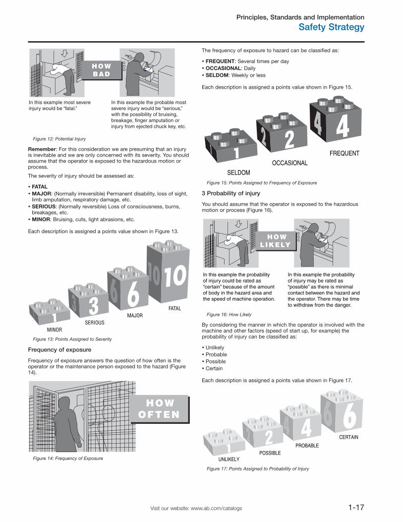
Principles, Standards and Implementation
Safety Strategy
1-17Visit our website: www.ab.com/catalogs
Remember: For this consideration we are presuming that an injuryis inevitable and we are only concerned with its severity. You shouldassume that the operator is exposed to the hazardous motion orprocess.
The severity of injury should be assessed as:
FATALMAJOR: (Normally irreversible) Permanent disability, loss of sight,limb amputation, respiratory damage, etc.SERIOUS: (Normally reversible) Loss of consciousness, burns,breakages, etc.MINOR: Bruising, cuts, light abrasions, etc.
Frequency of exposure
The frequency of exposure to hazard can be classified as:
FREQUENT: Several times per dayOCCASIONAL: DailySELDOM: Weekly or less
3 Probability of injury
By considering the manner in which the operator is involved with themachine and other factors (speed of start up, for example) theprobability of injury can be classified as:
UnlikelyProbablePossibleCertain
Each description is assigned a points value shown in Figure 13.
Frequency of exposure answers the question of how often is theoperator or the maintenance person exposed to the hazard (Figure14).
Each description is assigned a points value shown in Figure 15.
You should assume that the operator is exposed to the hazardousmotion or process (Figure 16).
Each description is assigned a points value shown in Figure 17.
MINORSERIOUS
MAJORFATAL
Figure 13: Points Assigned to Severity
HOWOFTEN
Figure 14: Frequency of Exposure
SELDOM
OCCASIONAL
FREQUENT12 4
Figure 15: Points Assigned to Frequency of Exposure
HOWLIKELY
In this example the probability of injury could be rated as“certain” because of the amountof body in the hazard area andthe speed of machine operation.
In this example the probabilityof injury may be rated as “possible” as there is minimal contact between the hazard andthe operator. There may be time to withdraw from the danger.
Figure 16: How Likely
4 62
1UNLIKELY
POSSIBLEPROBABLE
CERTAIN
Figure 17: Points Assigned to Probability of Injury
In this example most severe injury would be “fatal.”
In this example the probable most severe injury would be “serious,” with the possibility of bruising, breakage, finger amputation or injury from ejected chuck key, etc.
HOW BAD
Figure 12: Potential Injury
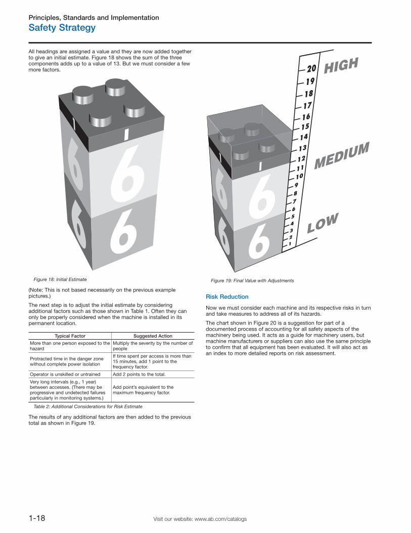
Principles, Standards and Implementation
Safety Strategy
1-18 Visit our website: www.ab.com/catalogs
Risk Reduction
All headings are assigned a value and they are now added togetherto give an initial estimate. Figure 18 shows the sum of the threecomponents adds up to a value of 13. But we must consider a fewmore factors.
(Note: This is not based necessarily on the previous examplepictures.)
The next step is to adjust the initial estimate by consideringadditional factors such as those shown in Table 1. Often they canonly be properly considered when the machine is installed in itspermanent location.
The results of any additional factors are then added to the previoustotal as shown in Figure 19.
Now we must consider each machine and its respective risks in turnand take measures to address all of its hazards.
The chart shown in Figure 20 is a suggestion for part of adocumented process of accounting for all safety aspects of themachinery being used. It acts as a guide for machinery users, butmachine manufacturers or suppliers can also use the same principleto confirm that all equipment has been evaluated. It will also act asan index to more detailed reports on risk assessment.
61
6Figure 18: Initial Estimate
61
6
HIGH
MEDIUM
LOW
Figure 19: Final Value with Adjustments
Typical Factor Suggested Action
More than one person exposed to thehazard
Multiply the severity by the number ofpeople
Protracted time in the danger zonewithout complete power isolation
If time spent per access is more than15 minutes, add 1 point to thefrequency factor.
Operator is unskilled or untrained Add 2 points to the total.
Very long intervals (e.g., 1 year)between accesses. (There may beprogressive and undetected failuresparticularly in monitoring systems.)
Add point’s equivalent to themaximum frequency factor.
Table 2: Additional Considerations for Risk Estimate
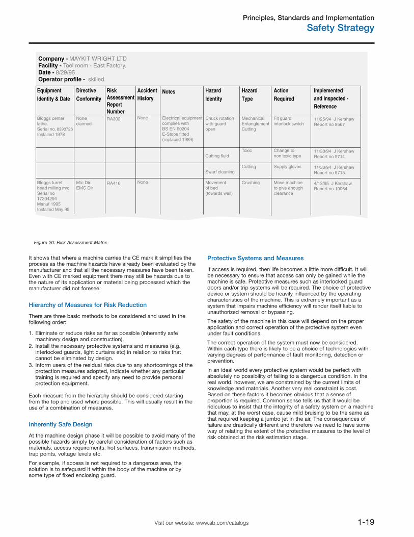
Principles, Standards and Implementation
Safety Strategy
1-19Visit our website: www.ab.com/catalogs
It shows that where a machine carries the CE mark it simplifies theprocess as the machine hazards have already been evaluated by themanufacturer and that all the necessary measures have been taken.Even with CE marked equipment there may still be hazards due tothe nature of its application or material being processed which themanufacturer did not foresee.
Hierarchy of Measures for Risk Reduction
There are three basic methods to be considered and used in thefollowing order:
1. Eliminate or reduce risks as far as possible (inherently safemachinery design and construction),
2. Install the necessary protective systems and measures (e.g.interlocked guards, light curtains etc) in relation to risks thatcannot be eliminated by design.
3. Inform users of the residual risks due to any shortcomings of theprotection measures adopted, indicate whether any particulartraining is required and specify any need to provide personalprotection equipment.
Each measure from the hierarchy should be considered startingfrom the top and used where possible. This will usually result in theuse of a combination of measures.
Inherently Safe Design
At the machine design phase it will be possible to avoid many of thepossible hazards simply by careful consideration of factors such asmaterials, access requirements, hot surfaces, transmission methods,trap points, voltage levels etc.
For example, if access is not required to a dangerous area, thesolution is to safeguard it within the body of the machine or bysome type of fixed enclosing guard.
Protective Systems and Measures
If access is required, then life becomes a little more difficult. It willbe necessary to ensure that access can only be gained while themachine is safe. Protective measures such as interlocked guarddoors and/or trip systems will be required. The choice of protectivedevice or system should be heavily influenced by the operatingcharacteristics of the machine. This is extremely important as asystem that impairs machine efficiency will render itself liable tounauthorized removal or bypassing.
The safety of the machine in this case will depend on the properapplication and correct operation of the protective system evenunder fault conditions.
The correct operation of the system must now be considered.Within each type there is likely to be a choice of technologies withvarying degrees of performance of fault monitoring, detection orprevention.
In an ideal world every protective system would be perfect withabsolutely no possibility of failing to a dangerous condition. In thereal world, however, we are constrained by the current limits ofknowledge and materials. Another very real constraint is cost.Based on these factors it becomes obvious that a sense ofproportion is required. Common sense tells us that it would beridiculous to insist that the integrity of a safety system on a machinethat may, at the worst case, cause mild bruising to be the same asthat required keeping a jumbo jet in the air. The consequences offailure are drastically different and therefore we need to have someway of relating the extent of the protective measures to the level ofrisk obtained at the risk estimation stage.
Company - MAYKIT WRIGHT LTDFacility - Tool room - East Factory.Date - 8/29/95Operator profile - skilled.
Equipment Identity & Date
Bloggs center lathe.Serial no. 8390726Installed 1978
Bloggs turret head milling m/cSerial no 17304294Manuf 1995Installed May 95
Notes
Electrical equipment complies with BS EN 60204E-Stops fitted (replaced 1989)
Hazard Type
Mechanical EntanglementCutting
Toxic
Cutting
Crushing
Action Required
Fit guard interlock switch
Change to non toxic type
Supply gloves
Move machineto give enoughclearance
Implemented and Inspected -Reference
11/25/94 J KershawReport no 9567
11/30/94 J KershawReport no 9714
11/30/94 J KershawReport no 9715
4/13/95 J KershawReport no 10064
Hazard Identity
Chuck rotation with guard open
Cutting fluid
Swarf cleaning
Movementof bed(towards wall)
AccidentHistory
None
None
Risk AssessmentReport NumberRA302
RA416
Directive Conformity
Noneclaimed
M/c Dir.EMC Dir
Figure 20: Risk Assessment Matrix
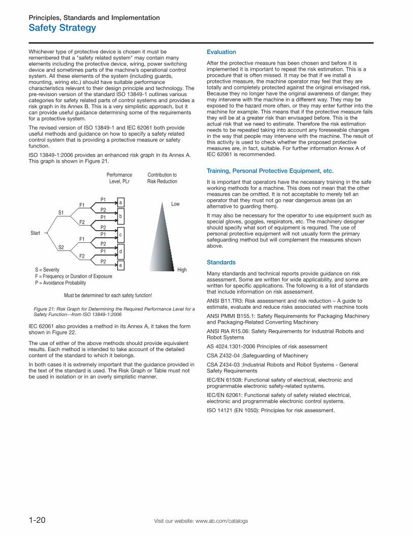
Principles, Standards and Implementation
Safety Strategy
1-20 Visit our website: www.ab.com/catalogs
The use of either of the above methods should provide equivalentresults. Each method is intended to take account of the detailedcontent of the standard to which it belongs.
In both cases it is extremely important that the guidance provided inthe text of the standard is used. The Risk Graph or Table must notbe used in isolation or in an overly simplistic manner.
Evaluation
After the protective measure has been chosen and before it isimplemented it is important to repeat the risk estimation. This is aprocedure that is often missed. It may be that if we install aprotective measure, the machine operator may feel that they aretotally and completely protected against the original envisaged risk.Because they no longer have the original awareness of danger, theymay intervene with the machine in a different way. They may beexposed to the hazard more often, or they may enter further into themachine for example. This means that if the protective measure failsthey will be at a greater risk than envisaged before. This is theactual risk that we need to estimate. Therefore the risk estimationneeds to be repeated taking into account any foreseeable changesin the way that people may intervene with the machine. The result ofthis activity is used to check whether the proposed protectivemeasures are, in fact, suitable. For further information Annex A ofIEC 62061 is recommended.
Training, Personal Protective Equipment, etc.
It is important that operators have the necessary training in the safeworking methods for a machine. This does not mean that the othermeasures can be omitted. It is not acceptable to merely tell anoperator that they must not go near dangerous areas (as analternative to guarding them).
It may also be necessary for the operator to use equipment such asspecial gloves, goggles, respirators, etc. The machinery designershould specify what sort of equipment is required. The use ofpersonal protective equipment will not usually form the primarysafeguarding method but will complement the measures shownabove.
Standards
Many standards and technical reports provide guidance on riskassessment. Some are written for wide applicability, and some arewritten for specific applications. The following is a list of standardsthat include information on risk assessment.
ANSI B11.TR3: Risk assessment and risk reduction – A guide toestimate, evaluate and reduce risks associated with machine tools
ANSI PMMI B155.1: Safety Requirements for Packaging Machineryand Packaging-Related Converting Machinery
ANSI RIA R15.06: Safety Requirements for Industrial Robots andRobot Systems
AS 4024.1301-2006 Principles of risk assessment
CSA Z432-04 ;Safeguarding of Machinery
CSA Z434-03 ;Industrial Robots and Robot Systems - GeneralSafety Requirements
IEC/EN 61508: Functional safety of electrical, electronic andprogrammable electronic safety-related systems.
IEC/EN 62061: Functional safety of safety related electrical,electronic and programmable electronic control systems.
ISO 14121 (EN 1050): Principles for risk assessment.
Whichever type of protective device is chosen it must beremembered that a "safety related system" may contain manyelements including the protective device, wiring, power switchingdevice and sometimes parts of the machine’s operational controlsystem. All these elements of the system (including guards,mounting, wiring etc.) should have suitable performancecharacteristics relevant to their design principle and technology. Thepre-revision version of the standard ISO 13849-1 outlines variouscategories for safety related parts of control systems and provides arisk graph in its Annex B. This is a very simplistic approach, but itcan provide useful guidance determining some of the requirementsfor a protective system.
The revised version of ISO 13849-1 and IEC 62061 both provideuseful methods and guidance on how to specify a safety relatedcontrol system that is providing a protective measure or safetyfunction.
ISO 13849-1:2006 provides an enhanced risk graph in its Annex A.This graph is shown in Figure 21.
IEC 62061 also provides a method in its Annex A, it takes the formshown in Figure 22.
Must be determined for each safety function!
S = SeverityF = Frequency or Duration of ExposureP = Avoidance Probability
P2
P1P2
P1
P2
P1P2
P1
F2
F1
F2
F1
S2
S1
Low
High
b
a
c
d
e
PerformanceLevel, PLr
Contribution toRisk Reduction
Start
Figure 21: Risk Graph for Determining the Required Performance Level for aSafety Function⎯from ISO 13849-1:2006
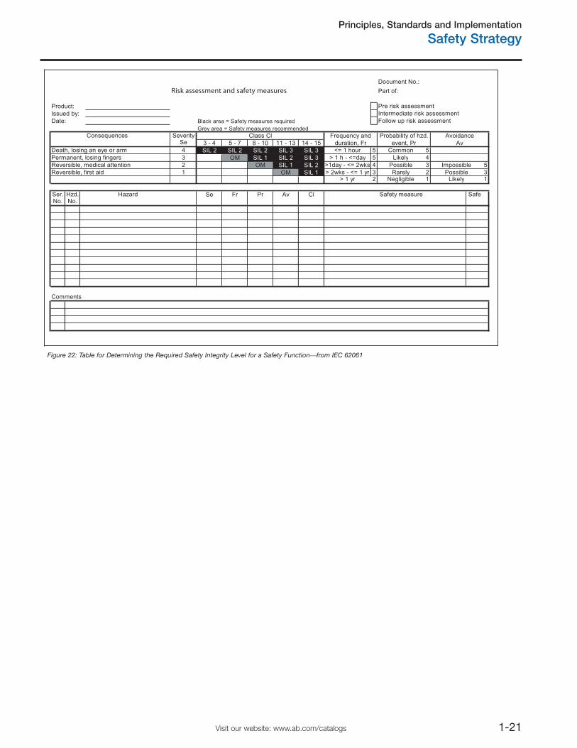
Principles, Standards and Implementation
Safety Strategy
1-21Visit our website: www.ab.com/catalogs
Docu me nt No .:
Risk assessment and safety measures Part of :
Pr e ri sk asse ssm en t
Interm ed ia te risk a sse ssm en t
Fo ll ow up ri sk asse ssm en t
Consequence s S everit ySe
Death, los in g an ey e or ar m 4 <= 1 ho u r 5 C om mo n 5
P erm anent, lo si ng fi nger s 3 > 1 h - <=d a y 5 L ik el y 4
Rev e rsi bl e, me dical attent io n 2 >1da y - <= 2w ks 4 P o ssi bl e 3 Im possi bl e 5
Reversi bl e, fi rst ai d 1 > 2w ks - <= 1 y r 3 R arel y 2 P o ssi bl e 3 > 1 y r 2 N egl igible 1 L ik el y 1
Ser. Hz d. Ha za rd Safety me as ur e Saf e No. No .
Com me nt s
Avoidanc e
durati on , F r ev en t , P r Av
Freq uenc y an d P robabil it y of hz d.
Product:
Date:
I ssued by :
Black area = Safety measures require d
Cl a ss Cl
14 - 15 3 - 4 5 - 7 8 - 10 11 - 13
SIL 2
OM
SI L 2
SIL 1
Fr
Gr e y area = Sa fe t y me asures reco mm ended
Cl Se P r Av
SI L 2
SI L 1 OM
SIL 2 S IL 3 S IL 3
SIL 1 S IL 2 S IL 3
OM
Figure 22: Table for Determining the Required Safety Integrity Level for a Safety Function⎯from IEC 62061
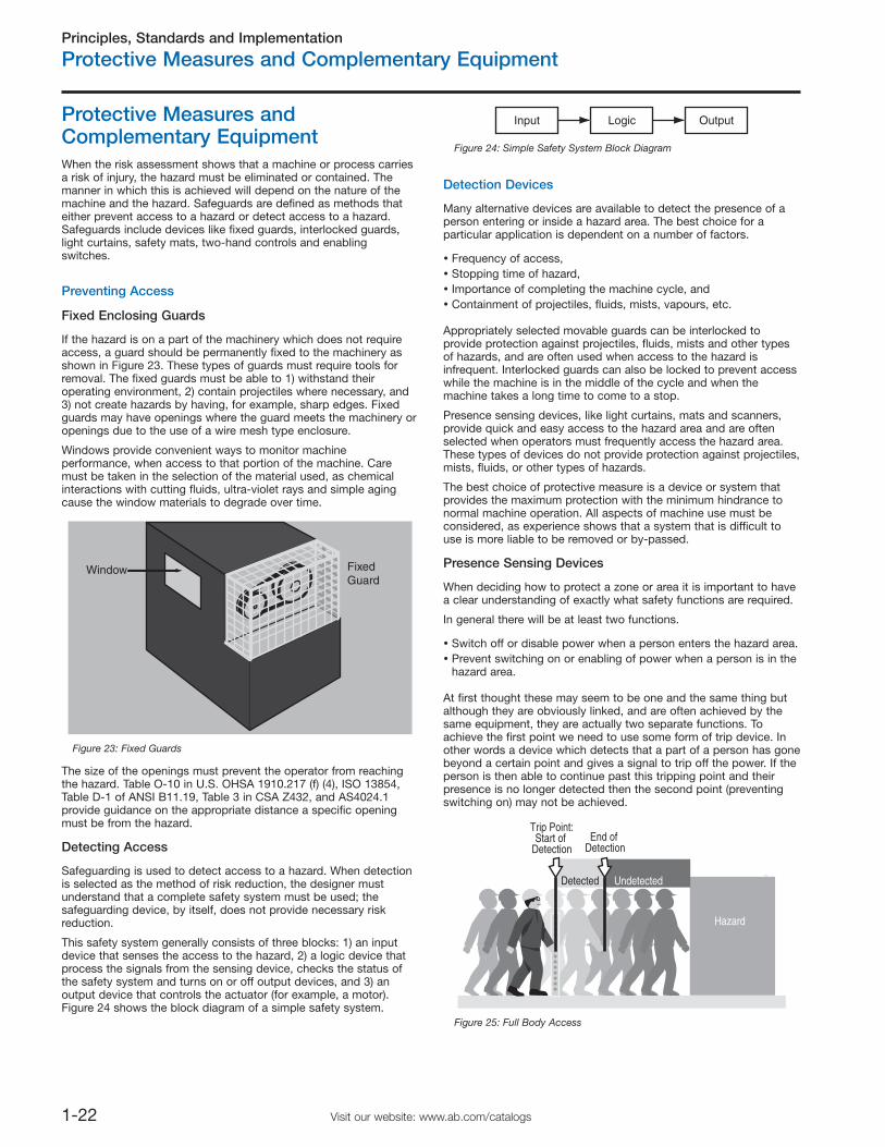
Principles, Standards and Implementation
Protective Measures and Complementary Equipment
1-22 Visit our website: www.ab.com/catalogs
Protective Measures andComplementary EquipmentWhen the risk assessment shows that a machine or process carriesa risk of injury, the hazard must be eliminated or contained. Themanner in which this is achieved will depend on the nature of themachine and the hazard. Safeguards are defined as methods thateither prevent access to a hazard or detect access to a hazard.Safeguards include devices like fixed guards, interlocked guards,light curtains, safety mats, two-hand controls and enablingswitches.
Preventing Access
Fixed Enclosing Guards
If the hazard is on a part of the machinery which does not requireaccess, a guard should be permanently fixed to the machinery asshown in Figure 23. These types of guards must require tools forremoval. The fixed guards must be able to 1) withstand theiroperating environment, 2) contain projectiles where necessary, and3) not create hazards by having, for example, sharp edges. Fixedguards may have openings where the guard meets the machinery oropenings due to the use of a wire mesh type enclosure.
Windows provide convenient ways to monitor machineperformance, when access to that portion of the machine. Caremust be taken in the selection of the material used, as chemicalinteractions with cutting fluids, ultra-violet rays and simple agingcause the window materials to degrade over time.
The size of the openings must prevent the operator from reachingthe hazard. Table O-10 in U.S. OHSA 1910.217 (f) (4), ISO 13854,Table D-1 of ANSI B11.19, Table 3 in CSA Z432, and AS4024.1provide guidance on the appropriate distance a specific openingmust be from the hazard.
Detecting Access
Safeguarding is used to detect access to a hazard. When detectionis selected as the method of risk reduction, the designer mustunderstand that a complete safety system must be used; thesafeguarding device, by itself, does not provide necessary riskreduction.
This safety system generally consists of three blocks: 1) an inputdevice that senses the access to the hazard, 2) a logic device thatprocess the signals from the sensing device, checks the status ofthe safety system and turns on or off output devices, and 3) anoutput device that controls the actuator (for example, a motor).Figure 24 shows the block diagram of a simple safety system.
Detection Devices
Many alternative devices are available to detect the presence of aperson entering or inside a hazard area. The best choice for aparticular application is dependent on a number of factors.
Frequency of access,Stopping time of hazard,Importance of completing the machine cycle, andContainment of projectiles, fluids, mists, vapours, etc.
Appropriately selected movable guards can be interlocked toprovide protection against projectiles, fluids, mists and other typesof hazards, and are often used when access to the hazard isinfrequent. Interlocked guards can also be locked to prevent accesswhile the machine is in the middle of the cycle and when themachine takes a long time to come to a stop.
Presence sensing devices, like light curtains, mats and scanners,provide quick and easy access to the hazard area and are oftenselected when operators must frequently access the hazard area.These types of devices do not provide protection against projectiles,mists, fluids, or other types of hazards.
The best choice of protective measure is a device or system thatprovides the maximum protection with the minimum hindrance tonormal machine operation. All aspects of machine use must beconsidered, as experience shows that a system that is difficult touse is more liable to be removed or by-passed.
Presence Sensing Devices
When deciding how to protect a zone or area it is important to havea clear understanding of exactly what safety functions are required.
In general there will be at least two functions.
Switch off or disable power when a person enters the hazard area.Prevent switching on or enabling of power when a person is in thehazard area.
At first thought these may seem to be one and the same thing butalthough they are obviously linked, and are often achieved by thesame equipment, they are actually two separate functions. Toachieve the first point we need to use some form of trip device. Inother words a device which detects that a part of a person has gonebeyond a certain point and gives a signal to trip off the power. If theperson is then able to continue past this tripping point and theirpresence is no longer detected then the second point (preventingswitching on) may not be achieved.
Window FixedGuard
Figure 23: Fixed Guards
Input Logic Output
Figure 24: Simple Safety System Block Diagram
Trip Point:Start of
DetectionEnd of
Detection
Detected Undetected
Hazard
Figure 25: Full Body Access
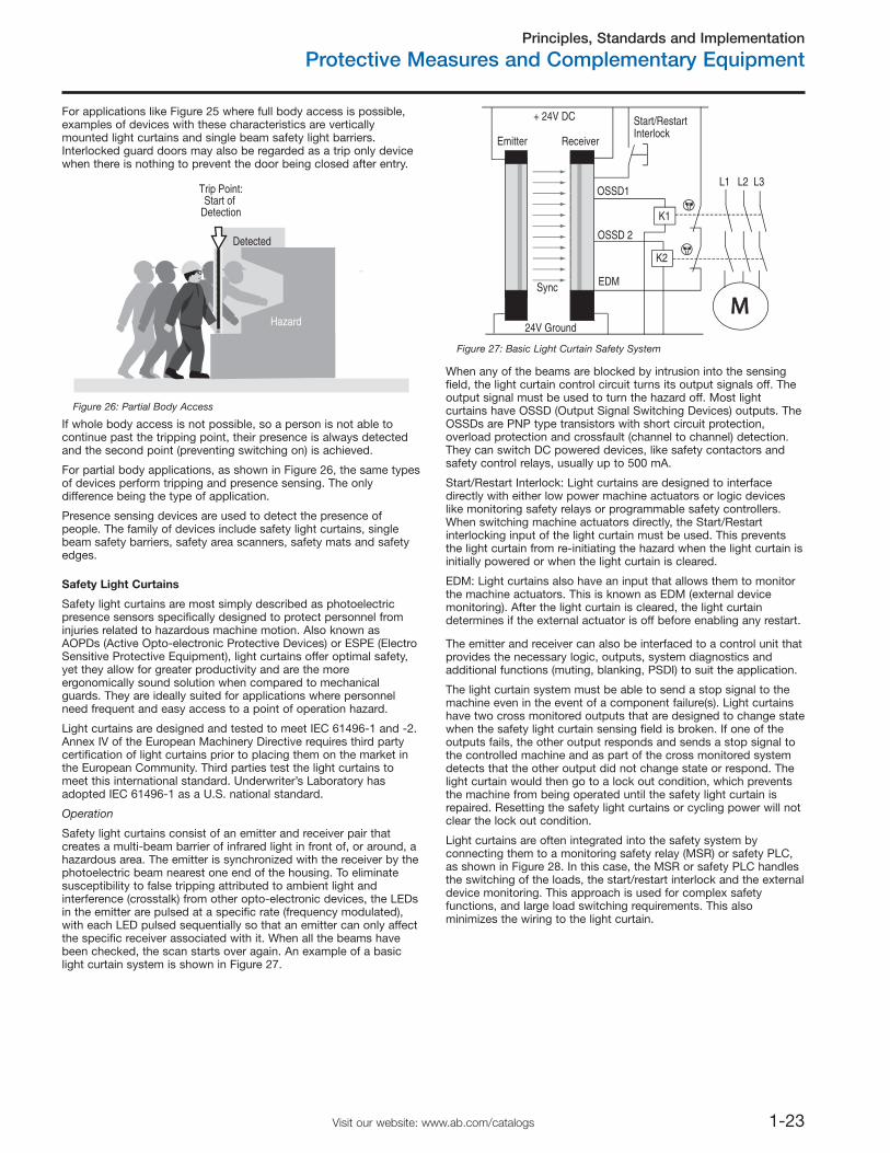
Principles, Standards and Implementation
Protective Measures and Complementary Equipment
1-23Visit our website: www.ab.com/catalogs
For applications like Figure 25 where full body access is possible,examples of devices with these characteristics are verticallymounted light curtains and single beam safety light barriers.Interlocked guard doors may also be regarded as a trip only devicewhen there is nothing to prevent the door being closed after entry.
If whole body access is not possible, so a person is not able tocontinue past the tripping point, their presence is always detectedand the second point (preventing switching on) is achieved.
For partial body applications, as shown in Figure 26, the same typesof devices perform tripping and presence sensing. The onlydifference being the type of application.
Presence sensing devices are used to detect the presence ofpeople. The family of devices include safety light curtains, singlebeam safety barriers, safety area scanners, safety mats and safetyedges.
Safety Light Curtains
Safety light curtains are most simply described as photoelectricpresence sensors specifically designed to protect personnel frominjuries related to hazardous machine motion. Also known asAOPDs (Active Opto-electronic Protective Devices) or ESPE (ElectroSensitive Protective Equipment), light curtains offer optimal safety,yet they allow for greater productivity and are the moreergonomically sound solution when compared to mechanicalguards. They are ideally suited for applications where personnelneed frequent and easy access to a point of operation hazard.
Light curtains are designed and tested to meet IEC 61496-1 and -2.Annex IV of the European Machinery Directive requires third partycertification of light curtains prior to placing them on the market inthe European Community. Third parties test the light curtains tomeet this international standard. Underwriter’s Laboratory hasadopted IEC 61496-1 as a U.S. national standard.
Operation
Safety light curtains consist of an emitter and receiver pair thatcreates a multi-beam barrier of infrared light in front of, or around, ahazardous area. The emitter is synchronized with the receiver by thephotoelectric beam nearest one end of the housing. To eliminatesusceptibility to false tripping attributed to ambient light andinterference (crosstalk) from other opto-electronic devices, the LEDsin the emitter are pulsed at a specific rate (frequency modulated),with each LED pulsed sequentially so that an emitter can only affectthe specific receiver associated with it. When all the beams havebeen checked, the scan starts over again. An example of a basiclight curtain system is shown in Figure 27.
Trip Point:Start of
Detection
Detected
Hazard
Figure 26: Partial Body Access
+ 24V DC
24V Ground
Emitter
OSSD1
OSSD 2
Receiver
K1
K2
L1 L3L2
Start/RestartInterlock
EDMSync
Figure 27: Basic Light Curtain Safety System
When any of the beams are blocked by intrusion into the sensingfield, the light curtain control circuit turns its output signals off. Theoutput signal must be used to turn the hazard off. Most lightcurtains have OSSD (Output Signal Switching Devices) outputs. TheOSSDs are PNP type transistors with short circuit protection,overload protection and crossfault (channel to channel) detection.They can switch DC powered devices, like safety contactors andsafety control relays, usually up to 500 mA.
Start/Restart Interlock: Light curtains are designed to interfacedirectly with either low power machine actuators or logic deviceslike monitoring safety relays or programmable safety controllers.When switching machine actuators directly, the Start/Restartinterlocking input of the light curtain must be used. This preventsthe light curtain from re-initiating the hazard when the light curtain isinitially powered or when the light curtain is cleared.
EDM: Light curtains also have an input that allows them to monitorthe machine actuators. This is known as EDM (external devicemonitoring). After the light curtain is cleared, the light curtaindetermines if the external actuator is off before enabling any restart.
The emitter and receiver can also be interfaced to a control unit thatprovides the necessary logic, outputs, system diagnostics andadditional functions (muting, blanking, PSDI) to suit the application.
The light curtain system must be able to send a stop signal to themachine even in the event of a component failure(s). Light curtainshave two cross monitored outputs that are designed to change statewhen the safety light curtain sensing field is broken. If one of theoutputs fails, the other output responds and sends a stop signal tothe controlled machine and as part of the cross monitored systemdetects that the other output did not change state or respond. Thelight curtain would then go to a lock out condition, which preventsthe machine from being operated until the safety light curtain isrepaired. Resetting the safety light curtains or cycling power will notclear the lock out condition.
Light curtains are often integrated into the safety system byconnecting them to a monitoring safety relay (MSR) or safety PLC,as shown in Figure 28. In this case, the MSR or safety PLC handlesthe switching of the loads, the start/restart interlock and the externaldevice monitoring. This approach is used for complex safetyfunctions, and large load switching requirements. This alsominimizes the wiring to the light curtain.
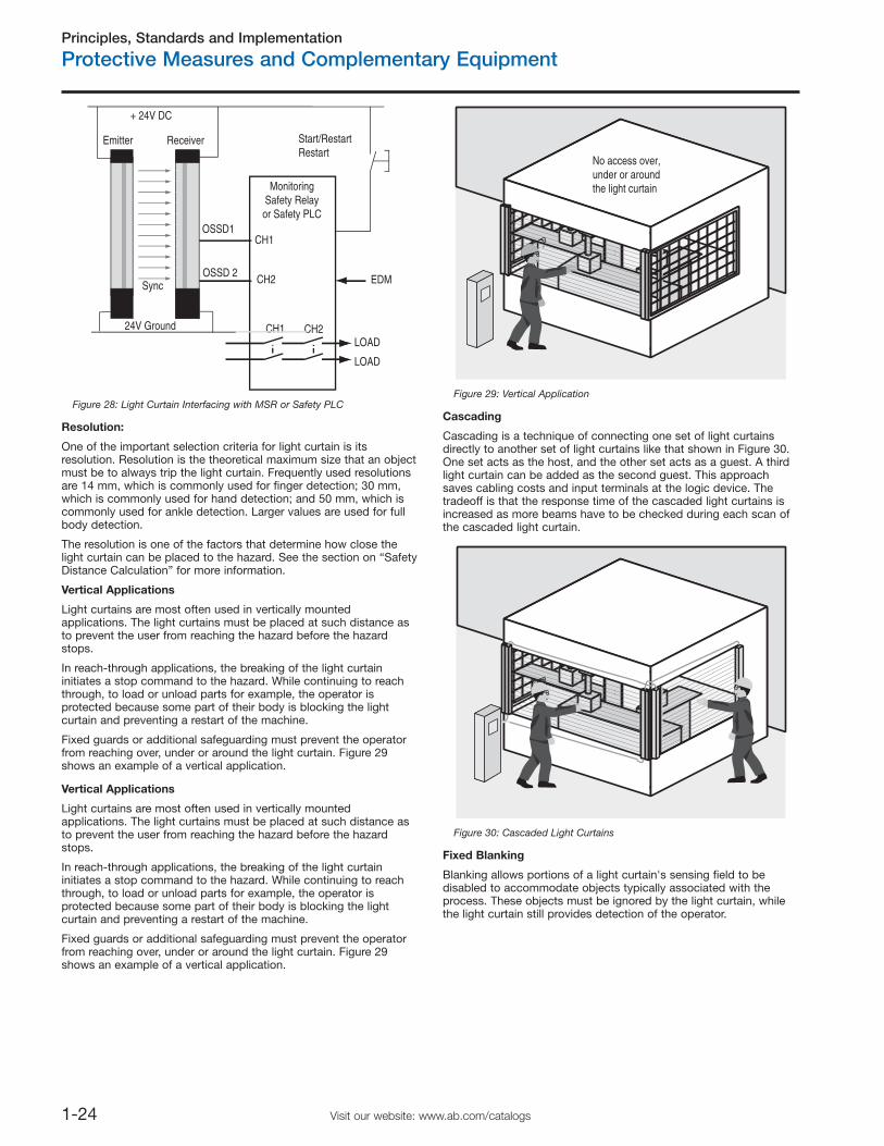
Principles, Standards and Implementation
Protective Measures and Complementary Equipment
1-24 Visit our website: www.ab.com/catalogs
CH1
CH2
MonitoringSafety Relay
or Safety PLC
CH1 CH2
+ 24V DC
24V Ground
Emitter
OSSD1
OSSD 2
Receiver Start/RestartRestart
EDM
LOAD
LOAD
Sync
Figure 28: Light Curtain Interfacing with MSR or Safety PLC
Resolution:
One of the important selection criteria for light curtain is itsresolution. Resolution is the theoretical maximum size that an objectmust be to always trip the light curtain. Frequently used resolutionsare 14 mm, which is commonly used for finger detection; 30 mm,which is commonly used for hand detection; and 50 mm, which iscommonly used for ankle detection. Larger values are used for fullbody detection.
The resolution is one of the factors that determine how close thelight curtain can be placed to the hazard. See the section on “SafetyDistance Calculation” for more information.
Vertical Applications
Light curtains are most often used in vertically mountedapplications. The light curtains must be placed at such distance asto prevent the user from reaching the hazard before the hazardstops.
In reach-through applications, the breaking of the light curtaininitiates a stop command to the hazard. While continuing to reachthrough, to load or unload parts for example, the operator isprotected because some part of their body is blocking the lightcurtain and preventing a restart of the machine.
Fixed guards or additional safeguarding must prevent the operatorfrom reaching over, under or around the light curtain. Figure 29shows an example of a vertical application.
No access over,under or aroundthe light curtain
Figure 29: Vertical Application
Cascading
Cascading is a technique of connecting one set of light curtainsdirectly to another set of light curtains like that shown in Figure 30.One set acts as the host, and the other set acts as a guest. A thirdlight curtain can be added as the second guest. This approachsaves cabling costs and input terminals at the logic device. Thetradeoff is that the response time of the cascaded light curtains isincreased as more beams have to be checked during each scan ofthe cascaded light curtain.
Figure 30: Cascaded Light Curtains
Fixed Blanking
Blanking allows portions of a light curtain's sensing field to bedisabled to accommodate objects typically associated with theprocess. These objects must be ignored by the light curtain, whilethe light curtain still provides detection of the operator.
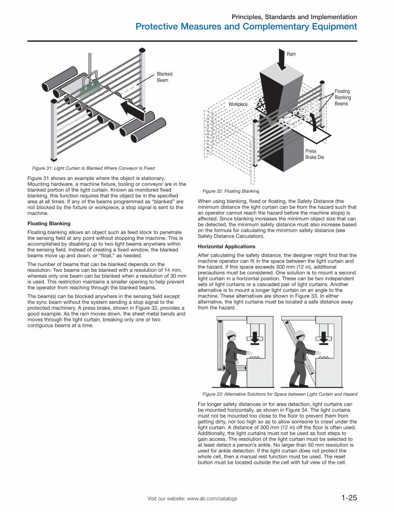
Principles, Standards and Implementation
Protective Measures and Complementary Equipment
1-25Visit our website: www.ab.com/catalogs
BlankedBeam
Figure 31: LIght Curtain Is Blanked Where Conveyor Is Fixed
Figure 31 shows an example where the object is stationary.Mounting hardware, a machine fixture, tooling or conveyor are in theblanked portion of the light curtain. Known as monitored fixedblanking, this function requires that the object be in the specifiedarea at all times. If any of the beams programmed as “blanked” arenot blocked by the fixture or workpiece, a stop signal is sent to themachine.
Floating Blanking
Floating blanking allows an object such as feed stock to penetratethe sensing field at any point without stopping the machine. This isaccomplished by disabling up to two light beams anywhere withinthe sensing field. Instead of creating a fixed window, the blankedbeams move up and down, or “float,” as needed.
The number of beams that can be blanked depends on theresolution. Two beams can be blanked with a resolution of 14 mm,whereas only one beam can be blanked when a resolution of 30 mmis used. This restriction maintains a smaller opening to help preventthe operator from reaching through the blanked beams.
The beam(s) can be blocked anywhere in the sensing field exceptthe sync beam without the system sending a stop signal to theprotected machinery. A press brake, shown in Figure 32, provides agood example. As the ram moves down, the sheet metal bends andmoves through the light curtain, breaking only one or twocontiguous beams at a time.
Workpiece
FloatingBlankingBeams
PressBrake Die
Ram
Figure 32: Floating Blanking
When using blanking, fixed or floating, the Safety Distance (theminimum distance the light curtain can be from the hazard such thatan operator cannot reach the hazard before the machine stops) isaffected. Since blanking increases the minimum object size that canbe detected, the minimum safety distance must also increase basedon the formula for calculating the minimum safety distance (seeSafety Distance Calculation).
Horizontal Applications
After calculating the safety distance, the designer might find that themachine operator can fit in the space between the light curtain andthe hazard. If this space exceeds 300 mm (12 in), additionalprecautions must be considered. One solution is to mount a secondlight curtain in a horizontal position. These can be two independentsets of light curtains or a cascaded pair of light curtains. Anotheralternative is to mount a longer light curtain on an angle to themachine. These alternatives are shown in Figure 33. In eitheralternative, the light curtains must be located a safe distance awayfrom the hazard.
Figure 33: Alternative Solutions for Space between Light Curtain and Hazard
For longer safety distances or for area detection, light curtains canbe mounted horizontally, as shown in Figure 34. The light curtainsmust not be mounted too close to the floor to prevent them fromgetting dirty, nor too high so as to allow someone to crawl under thelight curtain. A distance of 300 mm (12 in) off the floor is often used.Additionally, the light curtains must not be used as foot steps togain access. The resolution of the light curtain must be selected toat least detect a person’s ankle. No larger than 50 mm resolution isused for ankle detection. If the light curtain does not protect thewhole cell, then a manual rest function must be used. The resetbutton must be located outside the cell with full view of the cell.
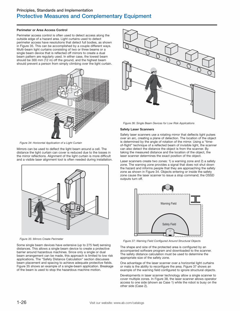
Principles, Standards and Implementation
Protective Measures and Complementary Equipment
1-26 Visit our website: www.ab.com/catalogs
Perimeter or Area Access Control
Perimeter access control is often used to detect access along theoutside edge of a hazard area. Light curtains used to detectperimeter access have resolutions that detect full bodies, as shownin Figure 35. This can be accomplished by a couple different ways.Multi-beam light curtains consisting of two or three beams or asingle beam device that is reflected off mirrors to create a dualbeam pattern are regularly used. In either case, the lowest beamshould be 300 mm (12 in) off the ground, and the highest beamshould prevent a person from simply climbing over the light curtain.
Figure 34: Horizontal Application of a Light Curtain
Mirrors can be used to deflect the light beam around a cell. Thedistance the light curtain can cover is reduced due to the losses inthe mirror reflections. Alignment of the light curtain is more difficultand a visible laser alignment tool is often needed during installation.
Figure 35: Mirrors Create Perimeter
Some single beam devices have extensive (up to 275 feet) sensingdistances. This allows a single beam device to create a protectivebarrier around hazardous machines. Since only a single or dualbeam arrangement can be made, this approach is limited to low riskapplications. The "Safety Distance Calculation" section discussesbeam placement and spacing to achieve adequate protective fields.Figure 35 shows an example of a single-beam application. Breakageof the beam is used to stop the hazardous machine motion.
Figure 36: Single Beam Devices for Low Risk Applications
Safety Laser Scanners
Safety laser scanners use a rotating mirror that deflects light pulsesover an arc, creating a plane of detection. The location of the objectis determined by the angle of rotation of the mirror. Using a “time-of-flight” technique of a reflected beam of invisible light, the scannercan also detect the distance the object is from the scanner. Bytaking the measured distance and the location of the object, thelaser scanner determines the exact position of the object.
Laser scanners create two zones: 1) a warning zone and 2) a safetyzone. The warning zone provides a signal that does not shut downthe hazard and informs people that they are approaching the safetyzone as shown in Figure 34. Objects entering or inside the safetyzone cause the laser scanner to issue a stop command; the OSSDoutputs turn off.
Warning Field
Safety Field
7
Figure 37: Warning Field Configured Around Structural Objects
The shape and size of the protected area is configured by anaccompanied software program and downloaded to the scanner.The safety distance calculation must be used to determine theappropriate size of the safety zone.
One advantage of the laser scanner over a horizontal light curtainsor mats is the ability to reconfigure the area. Figure 37 shows anexample of the warning field configured to ignore structural objects.
Developments in laser scanner technology allow a single scanner tocover multiple zones. In Figure 38, the laser scanner allows operatoraccess to one side (shown as Case 1) while the robot is busy on theother side (Case 2).
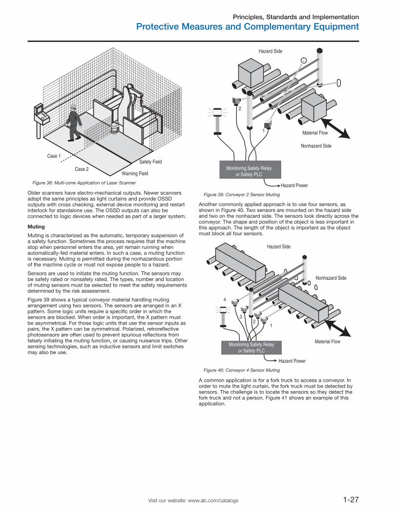
Principles, Standards and Implementation
Protective Measures and Complementary Equipment
1-27Visit our website: www.ab.com/catalogs
Safety Field
Warning Field
Case 1
Case 2
Figure 38: Multi-zone Application of Laser Scanner
Older scanners have electro-mechanical outputs. Newer scannersadopt the same principles as light curtains and provide OSSDoutputs with cross checking, external device monitoring and restartinterlock for standalone use. The OSSD outputs can also beconnected to logic devices when needed as part of a larger system.
Muting
Muting is characterized as the automatic, temporary suspension ofa safety function. Sometimes the process requires that the machinestop when personnel enters the area, yet remain running whenautomatically-fed material enters. In such a case, a muting functionis necessary. Muting is permitted during the nonhazardous portionof the machine cycle or must not expose people to a hazard.
Sensors are used to initiate the muting function. The sensors maybe safety rated or nonsafety rated. The types, number and locationof muting sensors must be selected to meet the safety requirementsdetermined by the risk assessment.
Figure 39 shows a typical conveyor material handling mutingarrangement using two sensors. The sensors are arranged in an Xpattern. Some logic units require a specific order in which thesensors are blocked. When order is important, the X pattern mustbe asymmetrical. For those logic units that use the sensor inputs aspairs, the X pattern can be symmetrical. Polarized, retroreflectivephotosensors are often used to prevent spurious reflections fromfalsely initiating the muting function, or causing nuisance trips. Othersensing technologies, such as inductive sensors and limit switchesmay also be use.
2
1 Material Flow
Hazard Side
Nonhazard Side
Hazard Power
Monitoring Safety Relayor Safety PLC
Figure 39: Conveyor 2 Sensor Muting
Another commonly applied approach is to use four sensors, asshown in Figure 40. Two sensors are mounted on the hazard sideand two on the nonhazard side. The sensors look directly across theconveyor. The shape and position of the object is less important inthis approach. The length of the object is important as the objectmust block all four sensors.
23
4
1
Material Flow
Hazard Side
Nonhazard Side
Hazard Power
Monitoring Safety Relayor Safety PLC
Figure 40: Conveyor 4 Sensor Muting
A common application is for a fork truck to access a conveyor. Inorder to mute the light curtain, the fork truck must be detected bysensors. The challenge is to locate the sensors so they detect thefork truck and not a person. Figure 41 shows an example of thisapplication.
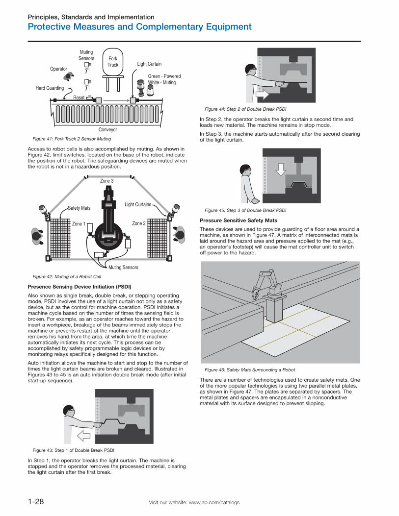
Principles, Standards and Implementation
Protective Measures and Complementary Equipment
1-28 Visit our website: www.ab.com/catalogs
ForkTruck
Reset
Operator
Hard Guarding
Conveyor
MutingSensors
Green - PoweredWhite - Muting
Light Curtain
Figure 41: Fork Truck 2 Sensor Muting
Access to robot cells is also accomplished by muting. As shown inFigure 42, limit switches, located on the base of the robot, indicatethe position of the robot. The safeguarding devices are muted whenthe robot is not in a hazardous position.
Zone 3
Zone 1
Safety MatsLight Curtains
Zone 2
Muting Sensors
Figure 42: Muting of a Robot Cell
Presence Sensing Device Initiation (PSDI)
Also known as single break, double break, or stepping operatingmode, PSDI involves the use of a light curtain not only as a safetydevice, but as the control for machine operation. PSDI initiates amachine cycle based on the number of times the sensing field isbroken. For example, as an operator reaches toward the hazard toinsert a workpiece, breakage of the beams immediately stops themachine or prevents restart of the machine until the operatorremoves his hand from the area, at which time the machineautomatically initiates its next cycle. This process can beaccomplished by safety programmable logic devices or bymonitoring relays specifically designed for this function.
Auto initiation allows the machine to start and stop to the number oftimes the light curtain beams are broken and cleared. Illustrated inFigures 43 to 45 is an auto initiation double break mode (after initialstart-up sequence).
Figure 43: Step 1 of Double Break PSDI
In Step 1, the operator breaks the light curtain. The machine isstopped and the operator removes the processed material, clearingthe light curtain after the first break.
Figure 44: Step 2 of Double Break PSDI
In Step 2, the operator breaks the light curtain a second time andloads new material. The machine remains in stop mode.
In Step 3, the machine starts automatically after the second clearingof the light curtain.
Figure 45: Step 3 of Double Break PSDI
Pressure Sensitive Safety Mats
These devices are used to provide guarding of a floor area around amachine, as shown in Figure 47. A matrix of interconnected mats islaid around the hazard area and pressure applied to the mat (e.g.,an operator's footstep) will cause the mat controller unit to switchoff power to the hazard.
Figure 46: Safety Mats Surrounding a Robot
There are a number of technologies used to create safety mats. Oneof the more popular technologies is using two parallel metal plates,as shown in Figure 47. The plates are separated by spacers. Themetal plates and spacers are encapsulated in a nonconductivematerial with its surface designed to prevent slipping.
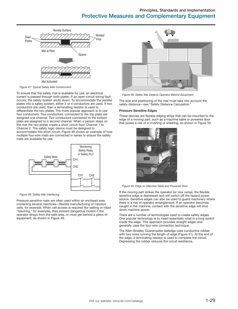
Principles, Standards and Implementation
Protective Measures and Complementary Equipment
1-29Visit our website: www.ab.com/catalogs
Mat at Rest
SteelPlates
Spacer
MoldedVinyl
Nonslip Surface
Mat Activated
Figure 47: Typical Safety Mat Construction
To ensure that the safety mat is available for use, an electricalcurrent is passed through both plates. If an open-circuit wiring faultoccurs, the safety system shuts down. To accommodate the parallelplates into a safety system, either 2 or 4 conductors are used. If twoconductors are used, then a terminating resistor is used todifferentiate the two plates. The more popular approach is to usefour conductors. Two conductors, connected to the top plate areassigned one channel. Two conductors connected to the bottomplate are assigned to a second channel. When a person steps onthe mat the two plates create a short circuit from Channel 1 toChannel 2. The safety logic device must be designed toaccommodate this short circuit. Figure 48 shows an example of howmultiple four-wire mats are connected in series to ensure the safetymats are available for use.
Safety Mats
CH1 CH2
MonitoringSafety Relayor Safety PLC
CH1
CH2
Figure 48: Safety Mat Interfacing
Pressure sensitive mats are often used within an enclosed areacontaining several machines—flexible manufacturing or roboticscells, for example. When cell access is required (for setting or robot"teaching," for example), they prevent dangerous motion if theoperator strays from the safe area, or must get behind a piece ofequipment, as shown in Figure 49.
Figure 49: Safety Mat Detects Operator Behind Equipment
The size and positioning of the mat must take into account thesafety distance⎯see "Safety Distance Calculation."
Pressure Sensitive Edges
These devices are flexible edging strips that can be mounted to theedge of a moving part, such as a machine table or powered doorthat poses a risk of a crushing or shearing, as shown in Figure 50.
Figure 50: Edge on Machine Table and Powered Door
If the moving part strikes the operator (or vice versa), the flexiblesensitive edge is depressed and will switch off the hazard powersource. Sensitive edges can also be used to guard machinery wherethere is a risk of operator entanglement. If an operator becomescaught in the machine, contact with the sensitive edge will shutdown machine power.
There are a number of technologies used to create safety edges.One popular technology is to insert essentially what is a long switchinside the edge. This approach provides straight edges andgenerally uses the four-wire connection technique.
The Allen-Bradley Guardmaster Safedge uses conductive rubber,with two wires running the length of edge (Figure 51). At the end ofthe edge, a terminating resistor is used to complete the circuit.Depressing the rubber reduces the circuit resistance.
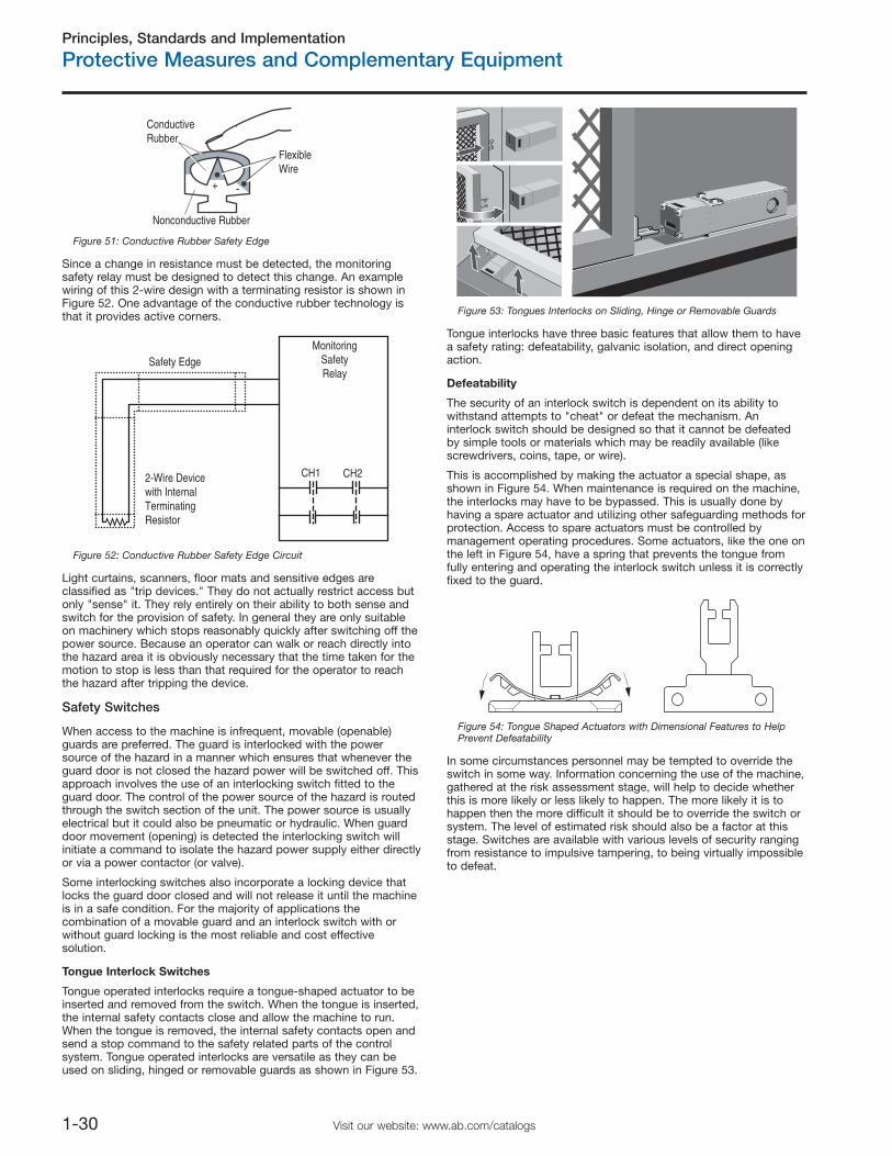
Principles, Standards and Implementation
Protective Measures and Complementary Equipment
1-30 Visit our website: www.ab.com/catalogs
ConductiveRubber
FlexibleWire
Nonconductive Rubber
+ -
Figure 51: Conductive Rubber Safety Edge
Since a change in resistance must be detected, the monitoringsafety relay must be designed to detect this change. An examplewiring of this 2-wire design with a terminating resistor is shown inFigure 52. One advantage of the conductive rubber technology isthat it provides active corners.
Safety Edge
2-Wire Devicewith InternalTerminatingResistor
CH1 CH2
MonitoringSafetyRelay
Figure 52: Conductive Rubber Safety Edge Circuit
Light curtains, scanners, floor mats and sensitive edges areclassified as "trip devices." They do not actually restrict access butonly "sense" it. They rely entirely on their ability to both sense andswitch for the provision of safety. In general they are only suitableon machinery which stops reasonably quickly after switching off thepower source. Because an operator can walk or reach directly intothe hazard area it is obviously necessary that the time taken for themotion to stop is less than that required for the operator to reachthe hazard after tripping the device.
Safety Switches
When access to the machine is infrequent, movable (openable)guards are preferred. The guard is interlocked with the powersource of the hazard in a manner which ensures that whenever theguard door is not closed the hazard power will be switched off. Thisapproach involves the use of an interlocking switch fitted to theguard door. The control of the power source of the hazard is routedthrough the switch section of the unit. The power source is usuallyelectrical but it could also be pneumatic or hydraulic. When guarddoor movement (opening) is detected the interlocking switch willinitiate a command to isolate the hazard power supply either directlyor via a power contactor (or valve).
Some interlocking switches also incorporate a locking device thatlocks the guard door closed and will not release it until the machineis in a safe condition. For the majority of applications thecombination of a movable guard and an interlock switch with orwithout guard locking is the most reliable and cost effectivesolution.
Tongue Interlock Switches
Tongue operated interlocks require a tongue-shaped actuator to beinserted and removed from the switch. When the tongue is inserted,the internal safety contacts close and allow the machine to run.When the tongue is removed, the internal safety contacts open andsend a stop command to the safety related parts of the controlsystem. Tongue operated interlocks are versatile as they can beused on sliding, hinged or removable guards as shown in Figure 53.
Figure 53: Tongues Interlocks on Sliding, Hinge or Removable Guards
Tongue interlocks have three basic features that allow them to havea safety rating: defeatability, galvanic isolation, and direct openingaction.
Defeatability
The security of an interlock switch is dependent on its ability towithstand attempts to "cheat" or defeat the mechanism. Aninterlock switch should be designed so that it cannot be defeatedby simple tools or materials which may be readily available (likescrewdrivers, coins, tape, or wire).
This is accomplished by making the actuator a special shape, asshown in Figure 54. When maintenance is required on the machine,the interlocks may have to be bypassed. This is usually done byhaving a spare actuator and utilizing other safeguarding methods forprotection. Access to spare actuators must be controlled bymanagement operating procedures. Some actuators, like the one onthe left in Figure 54, have a spring that prevents the tongue fromfully entering and operating the interlock switch unless it is correctlyfixed to the guard.
Figure 54: Tongue Shaped Actuators with Dimensional Features to HelpPrevent Defeatability
In some circumstances personnel may be tempted to override theswitch in some way. Information concerning the use of the machine,gathered at the risk assessment stage, will help to decide whetherthis is more likely or less likely to happen. The more likely it is tohappen then the more difficult it should be to override the switch orsystem. The level of estimated risk should also be a factor at thisstage. Switches are available with various levels of security rangingfrom resistance to impulsive tampering, to being virtually impossibleto defeat.
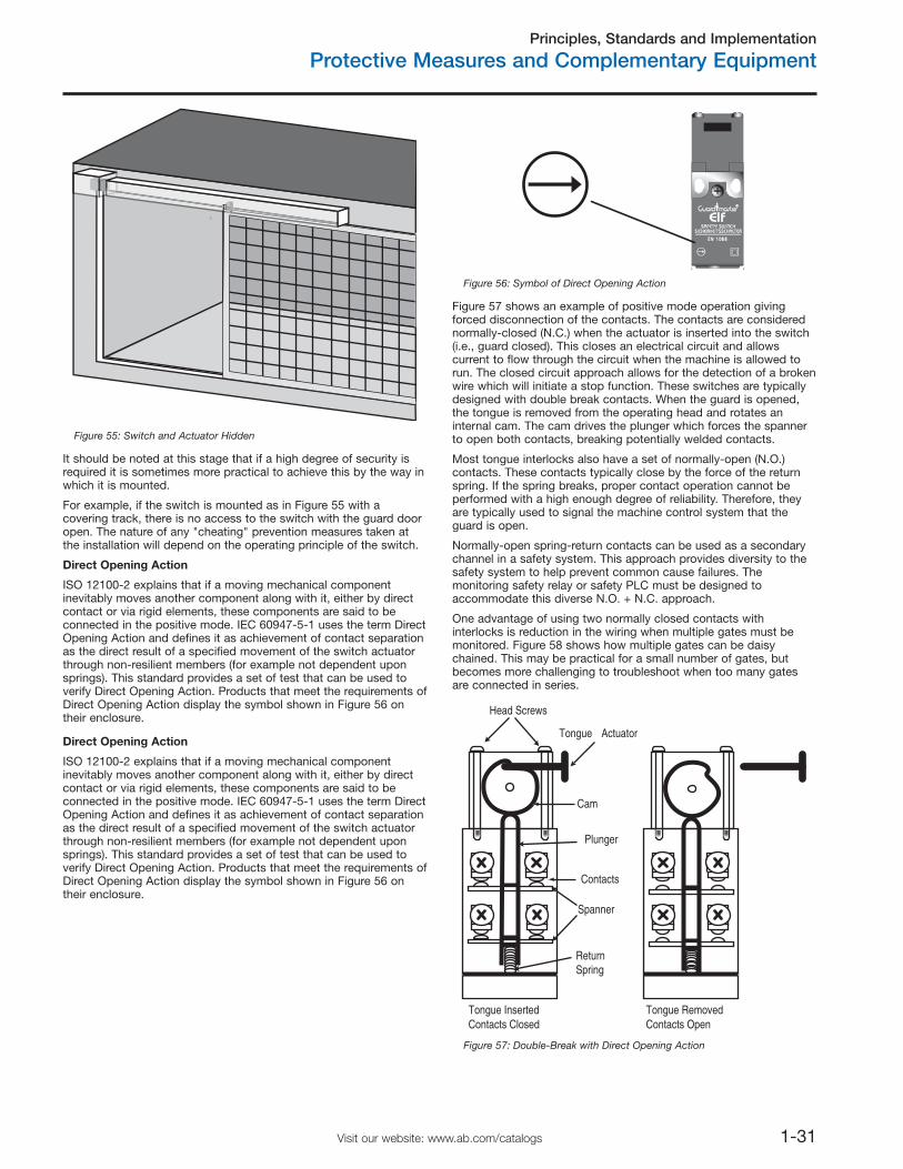
Principles, Standards and Implementation
Protective Measures and Complementary Equipment
1-31Visit our website: www.ab.com/catalogs
Figure 55: Switch and Actuator Hidden
It should be noted at this stage that if a high degree of security isrequired it is sometimes more practical to achieve this by the way inwhich it is mounted.
For example, if the switch is mounted as in Figure 55 with acovering track, there is no access to the switch with the guard dooropen. The nature of any "cheating" prevention measures taken atthe installation will depend on the operating principle of the switch.
Direct Opening Action
ISO 12100-2 explains that if a moving mechanical componentinevitably moves another component along with it, either by directcontact or via rigid elements, these components are said to beconnected in the positive mode. IEC 60947-5-1 uses the term DirectOpening Action and defines it as achievement of contact separationas the direct result of a specified movement of the switch actuatorthrough non-resilient members (for example not dependent uponsprings). This standard provides a set of test that can be used toverify Direct Opening Action. Products that meet the requirements ofDirect Opening Action display the symbol shown in Figure 56 ontheir enclosure.
Figure 56: Symbol of Direct Opening Action
Figure 57 shows an example of positive mode operation givingforced disconnection of the contacts. The contacts are considerednormally-closed (N.C.) when the actuator is inserted into the switch(i.e., guard closed). This closes an electrical circuit and allowscurrent to flow through the circuit when the machine is allowed torun. The closed circuit approach allows for the detection of a brokenwire which will initiate a stop function. These switches are typicallydesigned with double break contacts. When the guard is opened,the tongue is removed from the operating head and rotates aninternal cam. The cam drives the plunger which forces the spannerto open both contacts, breaking potentially welded contacts.
Most tongue interlocks also have a set of normally-open (N.O.)contacts. These contacts typically close by the force of the returnspring. If the spring breaks, proper contact operation cannot beperformed with a high enough degree of reliability. Therefore, theyare typically used to signal the machine control system that theguard is open.
Normally-open spring-return contacts can be used as a secondarychannel in a safety system. This approach provides diversity to thesafety system to help prevent common cause failures. Themonitoring safety relay or safety PLC must be designed toaccommodate this diverse N.O. + N.C. approach.
One advantage of using two normally closed contacts withinterlocks is reduction in the wiring when multiple gates must bemonitored. Figure 58 shows how multiple gates can be daisychained. This may be practical for a small number of gates, butbecomes more challenging to troubleshoot when too many gatesare connected in series.
Tongue Actuator
Head Screws
Cam
Plunger
Contacts
Spanner
ReturnSpring
Tongue RemovedContacts Open
Tongue InsertedContacts Closed
Figure 57: Double-Break with Direct Opening Action
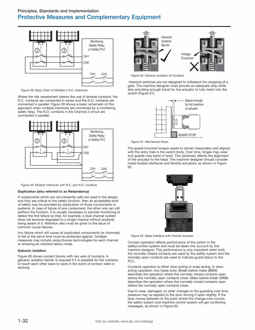
Principles, Standards and Implementation
Protective Measures and Complementary Equipment
1-32 Visit our website: www.ab.com/catalogs
CH1
CH1
CH2
CH2
MonitoringSafety Relay
or Safety PLC
Figure 58: Daisy Chain of Multiple 2 N.C. Interlocks
Where the risk assessment deems the use of diverse contacts, theN.C. contacts are connected in series and the N.O. contacts areconnected in parallel. Figure 59 shows a basic schematic of thisapproach when multiple interlocks are monitored by a monitoringsafety relay. The N.O. contacts in the Channel 2 circuit areconnected in parallel.
CH1
CH1
CH2
CH2
MonitoringSafety Relayor Safety PLC
Figure 59: Multiple Interlocks with N.C. and N.O. Contacts
Duplication (also referred to as Redundancy)
If components which are not inherently safe are used in the design,and they are critical to the safety function, then an acceptable levelof safety may be provided by duplication of those components orsystems. In case of failure of one component, the other one can stillperform the function. It is usually necessary to provide monitoring todetect the first failure so that, for example, a dual channel systemdoes not become degraded to a single channel without anybodybeing aware of it. Attention also must be given to the issue ofcommon cause failures.
Any failure which will cause all duplicated components (or channels)to fail at the same time must be protected against. Suitablemeasures may include using diverse technologies for each channelor ensuring an oriented failure mode.
Galvanic Isolation
Figure 60 shows contact blocks with two sets of contacts. Agalvanic isolation barrier is required if it is possible for the contactsto touch each other back to back in the event of contact weld orsticking.
GalvanicIsolationBarrier
VoltageCrossover
Figure 60: Galvanic Isolation of Contacts
Interlock switches are not designed to withstand the stopping of agate. The machine designer must provide an adequate stop whilealso providing enough travel for the actuator to fully insert into theswitch (Figure 61).
Space enoughfor full insertionof actuator
GUARD STOP
Figure 61: Mechanical Stops
The guard-mounted tongue needs to remain reasonably well alignedwith the entry hole in the switch body. Over time, hinges may wearand guards may bend or twist. This adversely affects the alignmentof the actuator to the head. The machine designer should considermetal bodied interfaces and flexible actuators, as shown in Figure62.
Figure 62: Metal Interface with Flexible Actuator
Contact operation affects performance of the switch in thesafety/control system and must be taken into account by themachine designer. This performance is only important when boththe normally closed contacts are used by the safety system and thenormally open contacts are used to indicate guard status to thePLC.
Contacts operation is either slow-acting or snap-acting. In slow-acting operation, two types exist. Break before make (BBM)describes the operation where the normally closed contacts openbefore the normally open contacts close. Make before break (MBB)describes the operation where the normally closed contacts openbefore the normally open contacts close.
Due to wear, damaged, or other changes to the guarding over time,pressure may be applied to the door forcing it open slightly. If thedoor moves between to the point where the change-over occurs,the safety system and machine control system will get conflictingmessages, as shown in Figure 63.
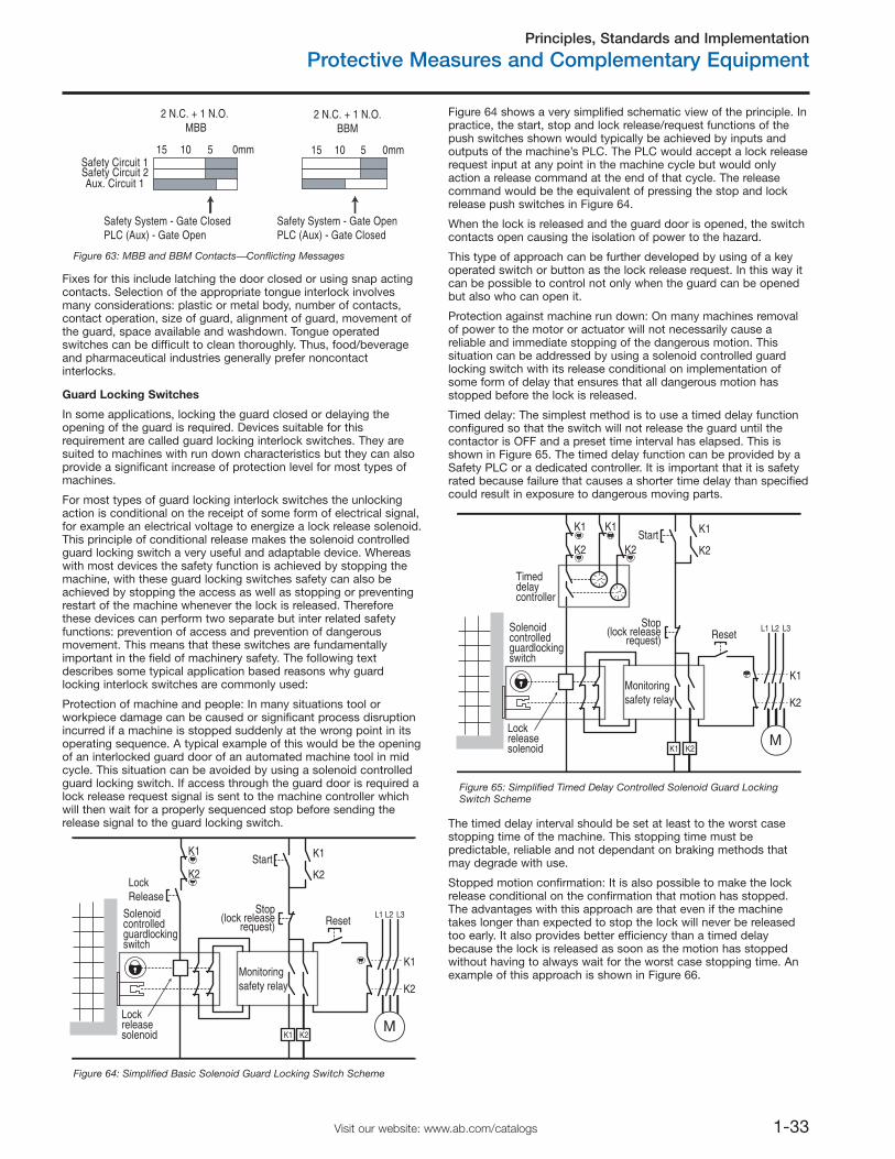
Principles, Standards and Implementation
Protective Measures and Complementary Equipment
1-33Visit our website: www.ab.com/catalogs
15 10 5 0mmSafety Circuit 1Safety Circuit 2Aux. Circuit 1
15 10 5 0mm
Safety System - Gate ClosedPLC (Aux) - Gate Open
Safety System - Gate OpenPLC (Aux) - Gate Closed
2 N.C. + 1 N.O. MBB
2 N.C. + 1 N.O.BBM
Figure 63: MBB and BBM Contacts⎯Conflicting Messages
Fixes for this include latching the door closed or using snap actingcontacts. Selection of the appropriate tongue interlock involvesmany considerations: plastic or metal body, number of contacts,contact operation, size of guard, alignment of guard, movement ofthe guard, space available and washdown. Tongue operatedswitches can be difficult to clean thoroughly. Thus, food/beverageand pharmaceutical industries generally prefer noncontactinterlocks.
Guard Locking Switches
In some applications, locking the guard closed or delaying theopening of the guard is required. Devices suitable for thisrequirement are called guard locking interlock switches. They aresuited to machines with run down characteristics but they can alsoprovide a significant increase of protection level for most types ofmachines.
For most types of guard locking interlock switches the unlockingaction is conditional on the receipt of some form of electrical signal,for example an electrical voltage to energize a lock release solenoid.This principle of conditional release makes the solenoid controlledguard locking switch a very useful and adaptable device. Whereaswith most devices the safety function is achieved by stopping themachine, with these guard locking switches safety can also beachieved by stopping the access as well as stopping or preventingrestart of the machine whenever the lock is released. Thereforethese devices can perform two separate but inter related safetyfunctions: prevention of access and prevention of dangerousmovement. This means that these switches are fundamentallyimportant in the field of machinery safety. The following textdescribes some typical application based reasons why guardlocking interlock switches are commonly used:
Protection of machine and people: In many situations tool orworkpiece damage can be caused or significant process disruptionincurred if a machine is stopped suddenly at the wrong point in itsoperating sequence. A typical example of this would be the openingof an interlocked guard door of an automated machine tool in midcycle. This situation can be avoided by using a solenoid controlledguard locking switch. If access through the guard door is required alock release request signal is sent to the machine controller whichwill then wait for a properly sequenced stop before sending therelease signal to the guard locking switch.
Figure 64 shows a very simplified schematic view of the principle. Inpractice, the start, stop and lock release/request functions of thepush switches shown would typically be achieved by inputs andoutputs of the machine’s PLC. The PLC would accept a lock releaserequest input at any point in the machine cycle but would onlyaction a release command at the end of that cycle. The releasecommand would be the equivalent of pressing the stop and lockrelease push switches in Figure 64.
When the lock is released and the guard door is opened, the switchcontacts open causing the isolation of power to the hazard.
This type of approach can be further developed by using of a keyoperated switch or button as the lock release request. In this way itcan be possible to control not only when the guard can be openedbut also who can open it.
Protection against machine run down: On many machines removalof power to the motor or actuator will not necessarily cause areliable and immediate stopping of the dangerous motion. Thissituation can be addressed by using a solenoid controlled guardlocking switch with its release conditional on implementation ofsome form of delay that ensures that all dangerous motion hasstopped before the lock is released.
Timed delay: The simplest method is to use a timed delay functionconfigured so that the switch will not release the guard until thecontactor is OFF and a preset time interval has elapsed. This isshown in Figure 65. The timed delay function can be provided by aSafety PLC or a dedicated controller. It is important that it is safetyrated because failure that causes a shorter time delay than specifiedcould result in exposure to dangerous moving parts.
The timed delay interval should be set at least to the worst casestopping time of the machine. This stopping time must bepredictable, reliable and not dependant on braking methods thatmay degrade with use.
Stopped motion confirmation: It is also possible to make the lockrelease conditional on the confirmation that motion has stopped.The advantages with this approach are that even if the machinetakes longer than expected to stop the lock will never be releasedtoo early. It also provides better efficiency than a timed delaybecause the lock is released as soon as the motion has stoppedwithout having to always wait for the worst case stopping time. Anexample of this approach is shown in Figure 66.
Solenoidcontrolledguardlockingswitch
Lockreleasesolenoid
LockRelease
K1
Stop(lock release
request)
Monitoringsafety relay
Start
Reset
K1
L1 L2 L3
K2
K2
MK1 K2
K1
K2
Figure 64: Simplified Basic Solenoid Guard Locking Switch Scheme
Solenoidcontrolledguardlockingswitch
Lockreleasesolenoid
K1
Stop(lock release
request)
Monitoringsafety relay
Start
Reset
K1
L1 L2 L3
K2
K2
MK1 K2
K1 K1
K2 K2
Timeddelaycontroller
Figure 65: Simplified Timed Delay Controlled Solenoid Guard LockingSwitch Scheme
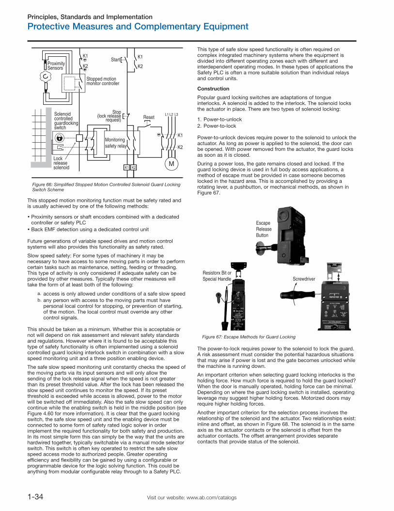
Principles, Standards and Implementation
Protective Measures and Complementary Equipment
1-34 Visit our website: www.ab.com/catalogs
This stopped motion monitoring function must be safety rated andis usually achieved by one of the following methods:
Proximity sensors or shaft encoders combined with a dedicatedcontroller or safety PLCBack EMF detection using a dedicated control unit
Future generations of variable speed drives and motion controlsystems will also provides this functionality as safety rated.
Slow speed safety: For some types of machinery it may benecessary to have access to some moving parts in order to performcertain tasks such as maintenance, setting, feeding or threading.This type of activity is only considered if adequate safety can beprovided by other measures. Typically these other measures willtake the form of at least both of the following:
a. access is only allowed under conditions of a safe slow speedb. any person with access to the moving parts must have
personal local control for stopping, or prevention of starting,of the motion. The local control must override any othercontrol signals.
Construction
Popular guard locking switches are adaptations of tongueinterlocks. A solenoid is added to the interlock. The solenoid locksthe actuator in place. There are two types of solenoid locking:
1. Power-to-unlock2. Power-to-lock
Power-to-unlock devices require power to the solenoid to unlock theactuator. As long as power is applied to the solenoid, the door canbe opened. With power removed from the actuator, the guard locksas soon as it is closed.
During a power loss, the gate remains closed and locked. If theguard locking device is used in full body access applications, amethod of escape must be provided in case someone becomeslocked in the hazard area. This is accomplished by providing arotating lever, a pushbutton, or mechanical methods, as shown inFigure 67.
The power-to-lock requires power to the solenoid to lock the guard.A risk assessment must consider the potential hazardous situationsthat may arise if power is lost and the gate becomes unlocked whilethe machine is running down.
An important criterion when selecting guard locking interlocks is theholding force. How much force is required to hold the guard locked?When the door is manually operated, holding force can be minimal.Depending on where the guard locking switch is installed, operatingleverage may suggest higher holding forces. Motorized doors mayrequire higher holding forces.
Another important criterion for the selection process involves therelationship of the solenoid and the actuator. Two relationships exist:inline and offset, as shown in Figure 68. The solenoid is in the sameaxis as the actuator contacts or the solenoid is offset from theactuator contacts. The offset arrangement provides separatecontacts that provide status of the solenoid.
Solenoidcontrolledguardlockingswitch
Lockreleasesolenoid
K1
Stop(lock release
request)
Monitoringsafety relay
Start
Reset
K1
L1 L2 L3
K2
K2
MK1 K2
K1
K2
Stopped motionmonitor controller
ProximitySensors
Figure 66: Simplified Stopped Motion Controlled Solenoid Guard LockingSwitch Scheme
This should be taken as a minimum. Whether this is acceptable ornot will depend on risk assessment and relevant safety standardsand regulations. However where it is found to be acceptable thistype of safety functionality is often implemented using a solenoidcontrolled guard locking interlock switch in combination with a slowspeed monitoring unit and a three position enabling device.
The safe slow speed monitoring unit constantly checks the speed ofthe moving parts via its input sensors and will only allow thesending of the lock release signal when the speed is not greaterthan its preset threshold value. After the lock has been released theslow speed unit continues to monitor the speed. If its presetthreshold is exceeded while access is allowed, power to the motorwill be switched off immediately. Also the safe slow speed can onlycontinue while the enabling switch is held in the middle position (seeFigure 4.60 for more information). It is clear that the guard lockingswitch, the safe slow speed unit and the enabling device must beconnected to some form of safety rated logic solver in orderimplement the required functionality for both safety and production.In its most simple form this can simply be the way that the units arehardwired together, typically switchable via a manual mode selectorswitch. This switch is often key operated to restrict the safe slowspeed access mode to authorized people. Greater operatingefficiency and flexibility can be gained by using a configurable orprogrammable device for the logic solving function. This could beanything from modular configurable relay through to a Safety PLC.
This type of safe slow speed functionality is often required oncomplex integrated machinery systems where the equipment isdivided into different operating zones each with different andinterdependent operating modes. In these types of applications theSafety PLC is often a more suitable solution than individual relaysand control units.
ScrewdriverResistorx Bit orSpecial Handle
EscapeReleaseButton
Figure 67: Escape Methods for Guard Locking
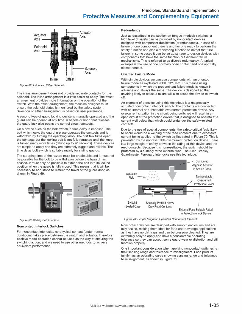
Principles, Standards and Implementation
Protective Measures and Complementary Equipment
1-35Visit our website: www.ab.com/catalogs
The inline arrangement does not provide separate contacts for thesolenoid. The inline arrangement is a little easier to apply. The offsetarrangement provides more information on the operation of theswitch. With the offset arrangement, the machine designer mustensure the solenoid status is monitored by the safety system.Selection of either arrangement is based on user preference.
A second type of guard locking device is manually operated and theguard can be opened at any time. A handle or knob that releasesthe guard lock also opens the control circuit contacts.
On a device such as the bolt switch, a time delay is imposed. Thebolt which locks the guard in place operates the contacts and iswithdrawn by turning the operating knob. The first few turns openthe contacts but the locking bolt is not fully retracted until the knobis turned many more times (taking up to 20 seconds). These devicesare simple to apply and they are extremely rugged and reliable. Thetime delay bolt switch is suitable mainly for sliding guards.
The stopping time of the hazard must be predictable and it must notbe possible for the bolt to be withdrawn before the hazard hasceased. It must only be possible to extend the bolt into its lockedposition when the guard is fully closed. This means that it will benecessary to add stops to restrict the travel of the guard door, asshown in Figure 69.
Figure 69: Sliding Bolt Interlock
Noncontact Interlock Switches
For noncontact interlocks, no physical contact (under normalconditions) takes place between the switch and actuator. Thereforepositive mode operation cannot be used as the way of ensuring theswitching action, and we need to use other methods to achieveequivalent performance.
Redundancy
Just as described in the section on tongue interlock switches, ahigh level of safety can be provided by noncontact devicesdesigned with component duplication (or redundancy). In case of afailure of one component there is another one ready to perform thesafety function and also a monitoring function to detect that firstfailure. In some cases it can be an advantage to design devices withcomponents that have the same function but different failuremechanisms. This is referred to as diverse redundancy. A typicalexample is the use of one normally open contact and one normallyclosed contact.
Oriented Failure Mode
With simple devices we can use components with an orientedfailure mode as explained in ISO 12100-2. This means usingcomponents in which the predominant failure mode is known inadvance and always the same. The device is designed so thatanything likely to cause a failure will also cause the device to switchoff.
An example of a device using this technique is a magneticallyactuated noncontact interlock switch. The contacts are connectedwith an internal non-resettable overcurrent protection device. Anyovercurrent situation in the circuit being switched will result in anopen circuit at the protection device that is designed to operate at acurrent well below that which could endanger the safety-relatedcontacts.
Due to the use of special components, the safety-critical fault likelyto occur would be a welding of the reed contacts due to excessivecurrent being applied to the switch as illustrated in Figure 70. This isprevented by the nonresettable overcurrent protection device. Thereis a large margin of safety between the rating of this device and thereed contacts. Because it is nonresettable, the switch should beprotected by a suitably rated external fuse. The Allen-BradleyGuardmaster Ferrogard interlocks use this technique.
ConfiguredMagnetic Actuator
in Sealed Case
NonresettableOvercurrent
Protection Device
External Fuse Suitably Ratedto Protect Interlock Device
Specially Profiled HeavyDuty Reed Contacts
Switch inSealed Case
ActuationField
Figure 70: Simple Magnetic Operated Noncontact Interlock
Noncontact devices are designed with smooth enclosures and arefully sealed, making them ideal for food and beverage applicationsas they have no dirt traps and can be pressure cleaned. They areextremely easy to apply and have a considerable operatingtolerance so they can accept some guard wear or distortion and stillfunction properly.
One important consideration when applying noncontact switches istheir sensing range and tolerance to misalignment. Each productfamily has an operating curve showing sensing range and toleranceto misalignment, as shown in Figure 71.
ActuatorAxis
SolenoidAxis
ActuatorAxis
SolenoidAxis
OffsetInlineFigure 68: Inline and Offset Solenoid
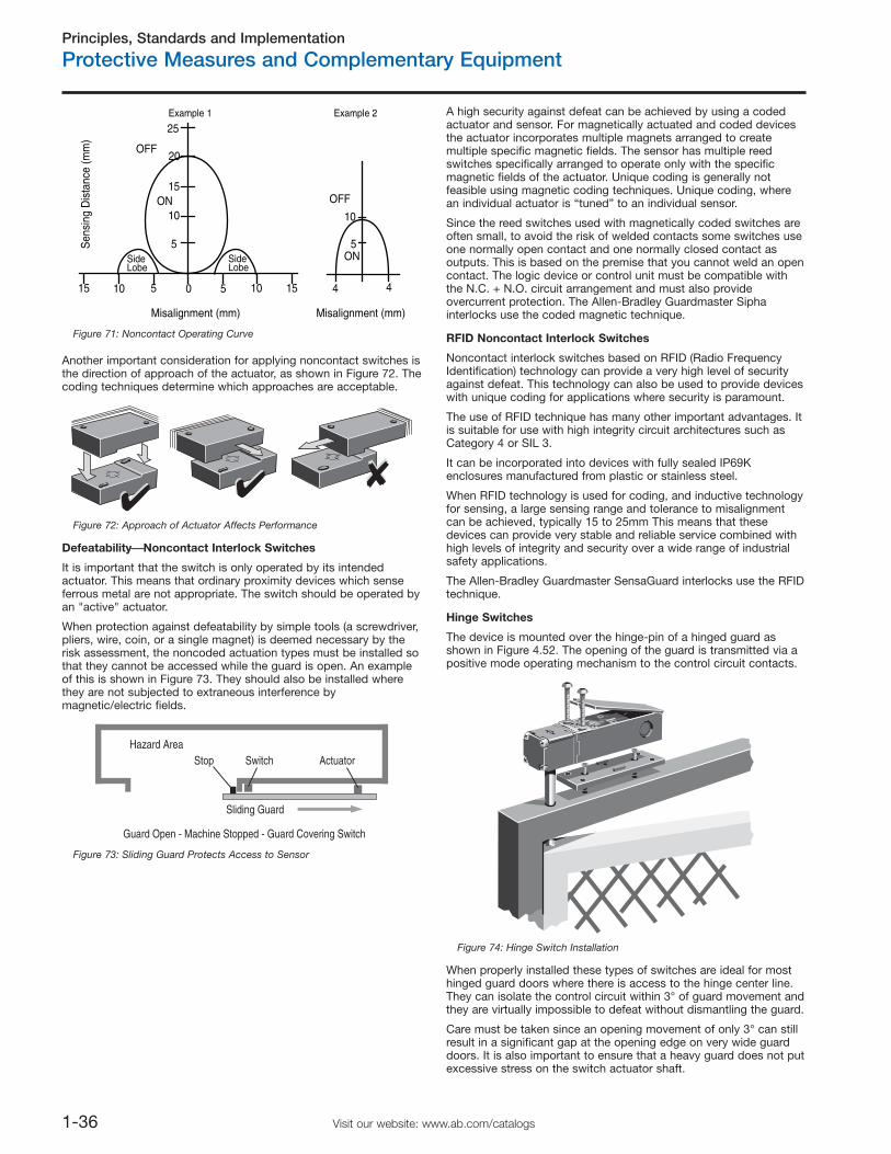
Principles, Standards and Implementation
Protective Measures and Complementary Equipment
1-36 Visit our website: www.ab.com/catalogs
Another important consideration for applying noncontact switches isthe direction of approach of the actuator, as shown in Figure 72. Thecoding techniques determine which approaches are acceptable.
Figure 72: Approach of Actuator Affects Performance
Defeatability⎯⎯Noncontact Interlock Switches
It is important that the switch is only operated by its intendedactuator. This means that ordinary proximity devices which senseferrous metal are not appropriate. The switch should be operated byan "active" actuator.
When protection against defeatability by simple tools (a screwdriver,pliers, wire, coin, or a single magnet) is deemed necessary by therisk assessment, the noncoded actuation types must be installed sothat they cannot be accessed while the guard is open. An exampleof this is shown in Figure 73. They should also be installed wherethey are not subjected to extraneous interference bymagnetic/electric fields.
Hazard AreaSwitchStop Actuator
Sliding Guard
Guard Open - Machine Stopped - Guard Covering Switch
Figure 73: Sliding Guard Protects Access to Sensor
A high security against defeat can be achieved by using a codedactuator and sensor. For magnetically actuated and coded devicesthe actuator incorporates multiple magnets arranged to createmultiple specific magnetic fields. The sensor has multiple reedswitches specifically arranged to operate only with the specificmagnetic fields of the actuator. Unique coding is generally notfeasible using magnetic coding techniques. Unique coding, wherean individual actuator is “tuned” to an individual sensor.
Since the reed switches used with magnetically coded switches areoften small, to avoid the risk of welded contacts some switches useone normally open contact and one normally closed contact asoutputs. This is based on the premise that you cannot weld an opencontact. The logic device or control unit must be compatible withthe N.C. + N.O. circuit arrangement and must also provideovercurrent protection. The Allen-Bradley Guardmaster Siphainterlocks use the coded magnetic technique.
RFID Noncontact Interlock Switches
Noncontact interlock switches based on RFID (Radio FrequencyIdentification) technology can provide a very high level of securityagainst defeat. This technology can also be used to provide deviceswith unique coding for applications where security is paramount.
The use of RFID technique has many other important advantages. Itis suitable for use with high integrity circuit architectures such asCategory 4 or SIL 3.
It can be incorporated into devices with fully sealed IP69Kenclosures manufactured from plastic or stainless steel.
When RFID technology is used for coding, and inductive technologyfor sensing, a large sensing range and tolerance to misalignmentcan be achieved, typically 15 to 25mm This means that thesedevices can provide very stable and reliable service combined withhigh levels of integrity and security over a wide range of industrialsafety applications.
The Allen-Bradley Guardmaster SensaGuard interlocks use the RFIDtechnique.
Hinge Switches
The device is mounted over the hinge-pin of a hinged guard asshown in Figure 4.52. The opening of the guard is transmitted via apositive mode operating mechanism to the control circuit contacts.
Figure 74: Hinge Switch Installation
When properly installed these types of switches are ideal for mosthinged guard doors where there is access to the hinge center line.They can isolate the control circuit within 3° of guard movement andthey are virtually impossible to defeat without dismantling the guard.
Care must be taken since an opening movement of only 3° can stillresult in a significant gap at the opening edge on very wide guarddoors. It is also important to ensure that a heavy guard does not putexcessive stress on the switch actuator shaft.
Misalignment (mm) Misalignment (mm)
Sen
sing
Dis
tanc
e (m
m)
5 4 45
5 5
10
15
0 1010
20
10
SideLobe
SideLobe
OFF
OFFON
ON
1515
25Example 1 Example 2
Figure 71: Noncontact Operating Curve
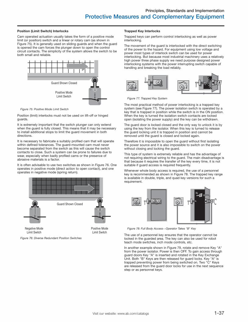
Principles, Standards and Implementation
Protective Measures and Complementary Equipment
1-37Visit our website: www.ab.com/catalogs
Position (Limit Switch) Interlocks
Cam operated actuation usually takes the form of a positive modelimit (or position) switch and a linear or rotary cam (as shown inFigure 75). It is generally used on sliding guards and when the guardis opened the cam forces the plunger down to open the controlcircuit contacts. The simplicity of the system allows the switch to beboth small and reliable.
Guard Shown Closed
Positive ModeLimit Switch
Figure 75: Positive Mode Limit Switch
Position (limit) interlocks must not be used on lift-off or hingedguards.
It is extremely important that the switch plunger can only extendwhen the guard is fully closed. This means that it may be necessaryto install additional stops to limit the guard movement in bothdirections.
It is necessary to fabricate a suitably profiled cam that will operatewithin defined tolerances. The guard-mounted cam must neverbecome separated from the switch as this will cause the switchcontacts to close. Such a system can be prone to failures due towear, especially when badly profiled cams or the presence ofabrasive materials is a factor.
It is often advisable to use two switches as shown in Figure 76. Oneoperates in positive mode (direct action to open contact), and oneoperates in negative mode (spring return).
Trapped Key Interlocks
Trapped keys can perform control interlocking as well as powerinterlocking.
The movement of the guard is interlocked with the direct switchingof the power to the hazard. For equipment using low voltage andpower most types of interlock switch can be used for powerinterlocking. But because most industrial machinery uses a relativelyhigh power three phase supply we need purpose designed powerinterlocking systems with the power interrupting switch capable ofhandling and breaking the load reliably.
A
AA
Figure 77: Trapped Key System
The most practical method of power interlocking is a trapped keysystem (see Figure 77). The power isolation switch is operated by akey that is trapped in position while the switch is in the ON position.When the key is turned the isolation switch contacts are lockedopen (isolating the power supply) and the key can be withdrawn.
The guard door is locked closed and the only way to unlock it is byusing the key from the isolator. When this key is turned to releasethe guard locking unit it is trapped in position and cannot beremoved until the guard is closed and locked again.
Therefore it is impossible to open the guard without first isolatingthe power source and it is also impossible to switch on the powerwithout closing and locking the guard.
This type of system is extremely reliable and has the advantage ofnot requiring electrical wiring to the guard. The main disadvantage isthat because it requires the transfer of the key every time, it is notsuitable if guard access is required frequently.
Whenever whole body access is required, the use of a personnelkey is recommended as shown in Figure 78. The trapped key rangeis available in double, triple, and quad key versions for such arequirement.
A AA
Figure 78: Full Body Access⎯Operator Takes "B" Key
The use of a personnel key ensures that the operator cannot belocked in the guarded area. The key can also be used for robotteach mode switches, inch mode controls, etc.
In another example shown in Figure 79, rotate and remove Key "A"from the power isolator. Power is then OFF. To gain access throughguard doors Key "A" is inserted and rotated in the Key ExchangeUnit. Both "B" Keys are then released for guard locks. Key "A" istrapped preventing power from being switched on. Two "C" Keysare released from the guard door locks for use in the next sequencestep or as personnel keys.
Positive ModeLimit Switch
Guard Shown Closed
Negative ModeLimit Switch
Figure 76: Diverse Redundant Position Switches
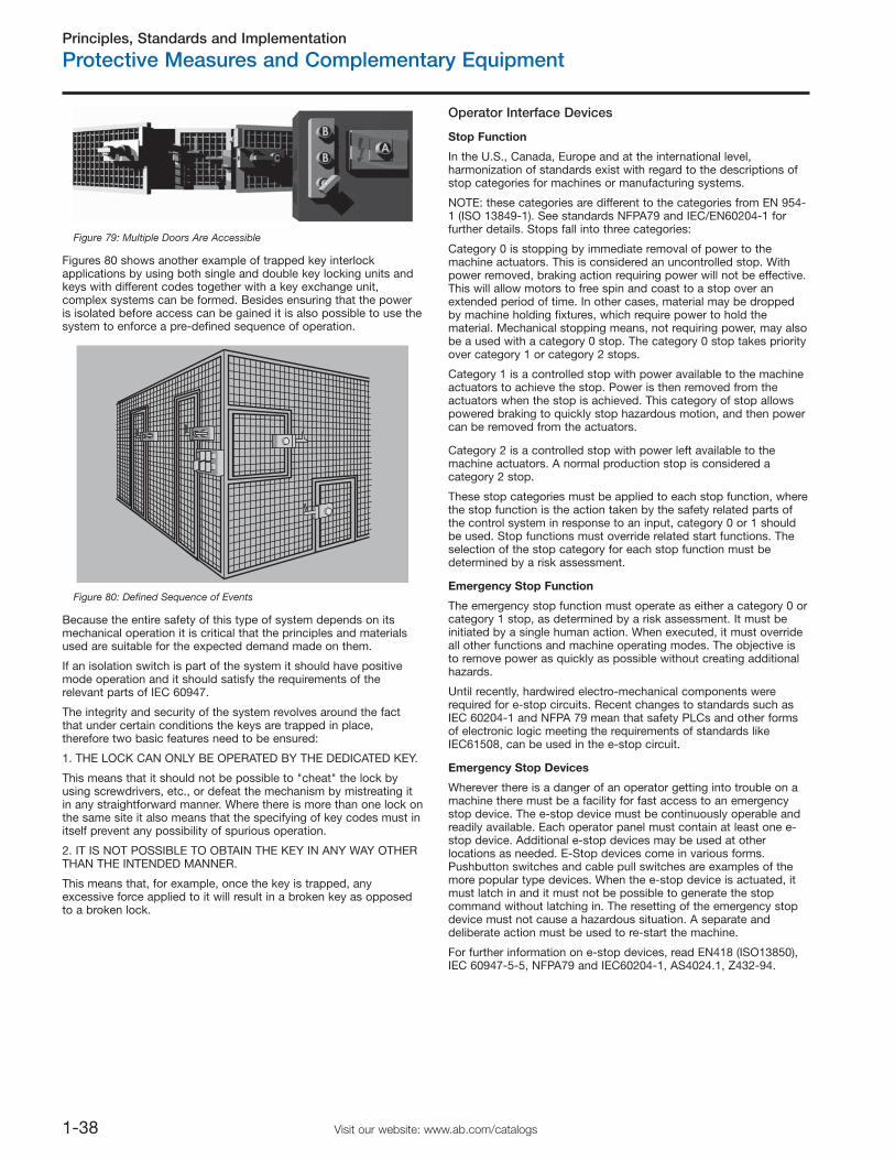
Principles, Standards and Implementation
Protective Measures and Complementary Equipment
1-38 Visit our website: www.ab.com/catalogs
Figure 79: Multiple Doors Are Accessible
Figures 80 shows another example of trapped key interlockapplications by using both single and double key locking units andkeys with different codes together with a key exchange unit,complex systems can be formed. Besides ensuring that the poweris isolated before access can be gained it is also possible to use thesystem to enforce a pre-defined sequence of operation.
Figure 80: Defined Sequence of Events
Because the entire safety of this type of system depends on itsmechanical operation it is critical that the principles and materialsused are suitable for the expected demand made on them.
If an isolation switch is part of the system it should have positivemode operation and it should satisfy the requirements of therelevant parts of IEC 60947.
The integrity and security of the system revolves around the factthat under certain conditions the keys are trapped in place,therefore two basic features need to be ensured:
1. THE LOCK CAN ONLY BE OPERATED BY THE DEDICATED KEY.
This means that it should not be possible to "cheat" the lock byusing screwdrivers, etc., or defeat the mechanism by mistreating itin any straightforward manner. Where there is more than one lock onthe same site it also means that the specifying of key codes must initself prevent any possibility of spurious operation.
2. IT IS NOT POSSIBLE TO OBTAIN THE KEY IN ANY WAY OTHERTHAN THE INTENDED MANNER.
This means that, for example, once the key is trapped, anyexcessive force applied to it will result in a broken key as opposedto a broken lock.
Operator Interface Devices
Stop Function
In the U.S., Canada, Europe and at the international level,harmonization of standards exist with regard to the descriptions ofstop categories for machines or manufacturing systems.
NOTE: these categories are different to the categories from EN 954-1 (ISO 13849-1). See standards NFPA79 and IEC/EN60204-1 forfurther details. Stops fall into three categories:
Category 0 is stopping by immediate removal of power to themachine actuators. This is considered an uncontrolled stop. Withpower removed, braking action requiring power will not be effective.This will allow motors to free spin and coast to a stop over anextended period of time. In other cases, material may be droppedby machine holding fixtures, which require power to hold thematerial. Mechanical stopping means, not requiring power, may alsobe a used with a category 0 stop. The category 0 stop takes priorityover category 1 or category 2 stops.
Category 1 is a controlled stop with power available to the machineactuators to achieve the stop. Power is then removed from theactuators when the stop is achieved. This category of stop allowspowered braking to quickly stop hazardous motion, and then powercan be removed from the actuators.
Category 2 is a controlled stop with power left available to themachine actuators. A normal production stop is considered acategory 2 stop.
These stop categories must be applied to each stop function, wherethe stop function is the action taken by the safety related parts ofthe control system in response to an input, category 0 or 1 shouldbe used. Stop functions must override related start functions. Theselection of the stop category for each stop function must bedetermined by a risk assessment.
Emergency Stop Function
The emergency stop function must operate as either a category 0 orcategory 1 stop, as determined by a risk assessment. It must beinitiated by a single human action. When executed, it must overrideall other functions and machine operating modes. The objective isto remove power as quickly as possible without creating additionalhazards.
Until recently, hardwired electro-mechanical components wererequired for e-stop circuits. Recent changes to standards such asIEC 60204-1 and NFPA 79 mean that safety PLCs and other formsof electronic logic meeting the requirements of standards likeIEC61508, can be used in the e-stop circuit.
Emergency Stop Devices
Wherever there is a danger of an operator getting into trouble on amachine there must be a facility for fast access to an emergencystop device. The e-stop device must be continuously operable andreadily available. Each operator panel must contain at least one e-stop device. Additional e-stop devices may be used at otherlocations as needed. E-Stop devices come in various forms.Pushbutton switches and cable pull switches are examples of themore popular type devices. When the e-stop device is actuated, itmust latch in and it must not be possible to generate the stopcommand without latching in. The resetting of the emergency stopdevice must not cause a hazardous situation. A separate anddeliberate action must be used to re-start the machine.
For further information on e-stop devices, read EN418 (ISO13850),IEC 60947-5-5, NFPA79 and IEC60204-1, AS4024.1, Z432-94.
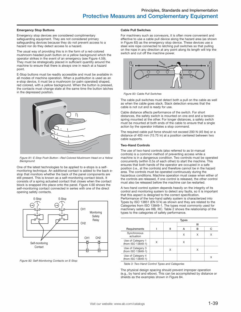
Principles, Standards and Implementation
Protective Measures and Complementary Equipment
1-39Visit our website: www.ab.com/catalogs
Emergency Stop Buttons
Emergency stop devices are considered complimentarysafeguarding equipment. They are not considered primarysafeguarding devices because they do not prevent access to ahazard nor do they detect access to a hazard.
The usual way of providing this is in the form of a red-coloredmushroom-headed push button on a yellow background which theoperator strikes in the event of an emergency (see Figure 4.59).They must be strategically placed in sufficient quantity around themachine to ensure that there is always one in reach at a hazardpoint.
E-Stop buttons must be readily accessible and must be available inall modes of machine operation. When a pushbutton is used as ane-stop device, it must be a mushroom (or palm operated) shaped,red colored, with a yellow background. When the button is pressed,the contacts must change state at the same time the button latchesin the depressed position.
Figure 81: E-Stop Push Button⎯Red Colored Mushroom Head on a YellowBackground
One of the latest technologies to be applied to e-stops is a self-monitoring technique. An additional contact is added to the back e-stop that monitors whether the back of the panel components arestill present. This is known as a self-monitoring contact block. Itconsists of a spring actuated contact that closes when the contactblock is snapped into place onto the panel. Figure 4.60 shows theself-monitoring contact connected in series with one of the directopening safety contacts.
E-StopE-Stop
CH1
CH1
CH2
CH2
MonitoringSafetyRelay
Self-monitoringContact
Figure 82: Self-Monitoring Contacts on E-Stop
Cable Pull Switches
For machinery such as conveyors, it is often more convenient andeffective to use a cable pull device along the hazard area (as shownin Figure 83) as the emergency stop device. These devices use asteel wire rope connected to latching pull switches so that pullingon the rope in any direction at any point along its length will trip theswitch and cut off the machine power.
Figure 83: Cable Pull Switches
The cable pull switches must detect both a pull on the cable as wellas when the cable goes slack. Slack detection ensures that thecable is not cut and is ready for use.
Cable distance affects performance of the switch. For shortdistances, the safety switch is mounted on one end and a tensionspring mounted at the other. For longer distances, a safety switchmust be mounted at both ends of the cable to ensure that a singleaction by the operator initiates a stop command.
The required cable pull force should not exceed 200 N (45 lbs) or adistance of 400 mm (15.75 in) at a position centered between twocable supports.
Two-Hand Controls
The use of two-hand controls (also referred to as bi-manualcontrols) is a common method of preventing access while amachine is in a dangerous condition. Two controls must be operatedconcurrently (within 0.5s of each other) to start the machine. Thisensures that both hands of the operator are occupied in a safeposition (i.e., at the controls) and therefore cannot be in the hazardarea. The controls must be operated continuously during thehazardous conditions. Machine operation must cease when either ofthe controls are released, if one control is released, the other controlmust also be released before the machine can be restarted.
A two-hand control system depends heavily on the integrity of itscontrol and monitoring system to detect any faults, so it is importantthat this aspect is designed to the correct specification.Performance of the two-hand safety system is characterized intoTypes by ISO 13851 (EN 574) as shown and they are related to theCategories from ISO 13849-1. The types most commonly used formachinery safety are IIIB, IIIC. Table 2 shows the relationship of thetypes to the categories of safety performance.
Requirements
Types
I II
III
A B C
Synchronousactuation X X X
Use of Category 1 (from ISO 13849-1) X X
Use of Category 3(from ISO 13849-1) X X
Use of Category 4(from ISO 13849-1) X
Table 3: Two-Hand Control Types and Categories
The physical design spacing should prevent improper operation(e.g., by hand and elbow). This can be accomplished by distance orshields as the examples shown in Figure 84.
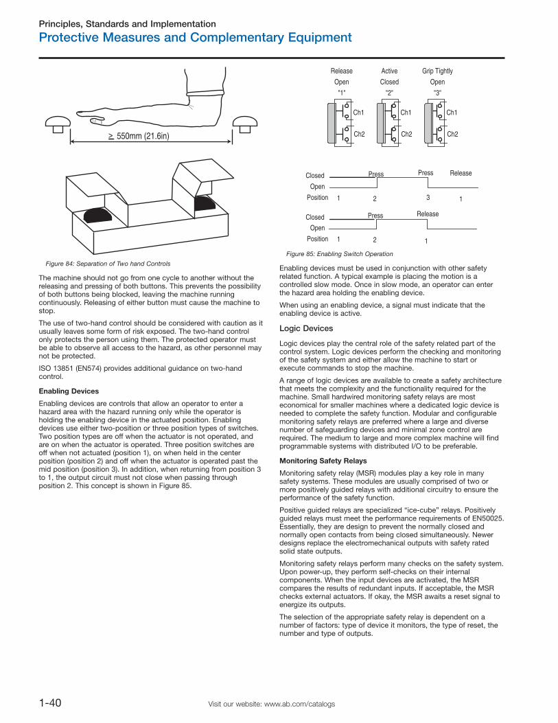
Principles, Standards and Implementation
Protective Measures and Complementary Equipment
1-40 Visit our website: www.ab.com/catalogs
550mm (21.6in)>
Figure 84: Separation of Two hand Controls
The machine should not go from one cycle to another without thereleasing and pressing of both buttons. This prevents the possibilityof both buttons being blocked, leaving the machine runningcontinuously. Releasing of either button must cause the machine tostop.
The use of two-hand control should be considered with caution as itusually leaves some form of risk exposed. The two-hand controlonly protects the person using them. The protected operator mustbe able to observe all access to the hazard, as other personnel maynot be protected.
ISO 13851 (EN574) provides additional guidance on two-handcontrol.
Enabling Devices
Enabling devices are controls that allow an operator to enter ahazard area with the hazard running only while the operator isholding the enabling device in the actuated position. Enablingdevices use either two-position or three position types of switches.Two position types are off when the actuator is not operated, andare on when the actuator is operated. Three position switches areoff when not actuated (position 1), on when held in the centerposition (position 2) and off when the actuator is operated past themid position (position 3). In addition, when returning from position 3to 1, the output circuit must not close when passing throughposition 2. This concept is shown in Figure 85.
Release
Open
"1"
Active
Closed
"2"
Grip Tightly
Open
"3"
Ch1
Ch2
Ch1
Ch2
Ch1
Ch2
Closed
Open
Position
Press Press
Closed
Open
Position
Press
Release
Release
1 2
1 2
1
13
Figure 85: Enabling Switch Operation
Enabling devices must be used in conjunction with other safetyrelated function. A typical example is placing the motion is acontrolled slow mode. Once in slow mode, an operator can enterthe hazard area holding the enabling device.
When using an enabling device, a signal must indicate that theenabling device is active.
Logic Devices
Logic devices play the central role of the safety related part of thecontrol system. Logic devices perform the checking and monitoringof the safety system and either allow the machine to start orexecute commands to stop the machine.
A range of logic devices are available to create a safety architecturethat meets the complexity and the functionality required for themachine. Small hardwired monitoring safety relays are mosteconomical for smaller machines where a dedicated logic device isneeded to complete the safety function. Modular and configurablemonitoring safety relays are preferred where a large and diversenumber of safeguarding devices and minimal zone control arerequired. The medium to large and more complex machine will findprogrammable systems with distributed I/O to be preferable.
Monitoring Safety Relays
Monitoring safety relay (MSR) modules play a key role in manysafety systems. These modules are usually comprised of two ormore positively guided relays with additional circuitry to ensure theperformance of the safety function.
Positive guided relays are specialized “ice-cube” relays. Positivelyguided relays must meet the performance requirements of EN50025.Essentially, they are design to prevent the normally closed andnormally open contacts from being closed simultaneously. Newerdesigns replace the electromechanical outputs with safety ratedsolid state outputs.
Monitoring safety relays perform many checks on the safety system.Upon power-up, they perform self-checks on their internalcomponents. When the input devices are activated, the MSRcompares the results of redundant inputs. If acceptable, the MSRchecks external actuators. If okay, the MSR awaits a reset signal toenergize its outputs.
The selection of the appropriate safety relay is dependent on anumber of factors: type of device it monitors, the type of reset, thenumber and type of outputs.
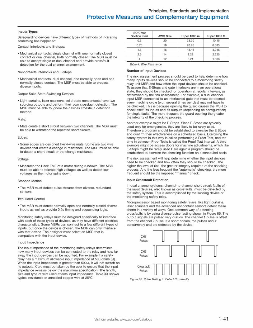
Principles, Standards and Implementation
Protective Measures and Complementary Equipment
1-41Visit our website: www.ab.com/catalogs
Inputs Types
Safeguarding devices have different types of methods of indicatingsomething has happened:
Contact Interlocks and E-stops:
Mechanical contacts, single channel with one normally closedcontact or dual channel, both normally closed. The MSR must beable to accept single or dual channel and provide crossfaultdetection for the dual channel arrangement.
Noncontacts Interlocks and E-Stops
Mechanical contacts, dual channel, one normally open and onenormally closed contact. The MSR must be able to processdiverse inputs.
Output Solid-State Switching Devices
Light curtains, laser scanners, solid-state noncontacts have twosourcing outputs and perform their own crossfault detection. TheMSR must be able to ignore the devices crossfault detectionmethod.
Mats:
Mats create a short circuit between two channels. The MSR mustbe able to withstand the repeated short circuits.
Edges:
Some edges are designed like 4-wire mats. Some are two wiredevices that create a change in resistance. The MSR must be ableto detect a short circuit or the change resistance.
Voltage
Measures the Back EMF of a motor during rundown. The MSRmust be able to tolerate high voltages as well as detect lowvoltages as the motor spins down.
Stopped Motion
The MSR must detect pulse streams from diverse, redundantsensors.
Two-Hand Control
The MSR must detect normally open and normally closed diverseinputs as well as provide 0.5s timing and sequencing logic.
Monitoring safety relays must be designed specifically to interfacewith each of these types of devices, as they have different electricalcharacteristics. Some MSRs can connect to a few different types ofinputs, but once the device is chosen, the MSR can only interfacewith that device. The designer must select an MSR that iscompatible with the input device.
Input Impedance
The input impedance of the monitoring safety relays determineshow many input devices can be connected to the relay and how faraway the input devices can be mounted. For example if a safetyrelay has a maximum allowable input impedance of 500 ohms (Ω).When the input impedance is greater than 500Ω, it will not switch onits outputs. Care must be taken by the user to ensure that the inputimpedance remains below the maximum specification. The length,size and type of wire used affects input impedance. Table XX showstypical resistance of annealed copper wire at 25°C.
Number of Input Devices
The risk assessment process should be used to help determine howmany inputs devices should be connected to a monitoring safetyrelay unit MSR and how often the input devices should be checked.To assure that E-Stops and gate interlocks are in an operationalstate, they should be checked for operation at regular intervals, asdetermined by the risk assessment. For example, a dual channelinput MSR connected to an interlocked gate that must be openedevery machine cycle (e.g., several times per day) may not have tobe checked. This is because opening the guard causes the MSR tocheck itself, its inputs and its outputs (depending on configuration)for single faults. The more frequent the guard opening the greaterthe integrity of the checking process.
Another example might be E-Stops. Since E-Stops are typicallyused only for emergencies, they are likely to be rarely used.Therefore a program should be established to exercise the E Stopsand confirm their effectiveness on a scheduled basis. Exercising thesafety system in this way is called performing a Proof Test, and thetime in between Proof Tests is called the Proof Test Interval. A thirdexample might be access doors for machine adjustments, which likeE-Stops might be rarely used Here again a program should beestablished to exercise the checking function on a scheduled basis
The risk assessment will help determine whether the input devicesneed to be checked and how often they should be checked. Thehigher the level of risk, the greater integrity required of the checkingprocess. And the less frequent the "automatic" checking, the morefrequent should be the imposed "manual" check.
Input Crossfault Detection
In dual channel systems, channel-to-channel short circuit faults ofthe input devices, also known as crossfaults, must be detected bythe safety system. This is accomplished by the sensing device orthe monitoring safety relay.
Microprocessor based monitoring safety relays, like light curtains,laser scanners and the advanced noncontact sensors detect theseshorts in a variety of ways. One common way of detectingcrossfaults is by using diverse pulse testing shown in Figure 86. Theoutput signals are pulsed very quickly. The channel 1 pulse is offsetfrom the channel 2 pulse. If a short occurs, the pulses occurconcurrently and are detected by the device.
CH1Pulses
CH2Pulses
CrossfaultPulses
Figure 86: Pulse Testing to Detect Crossfaults
ISO CrossSection mm2 AWG Size Ω per 1000 m Ω per 1000 ft
0.5 20 33.30 10.15
0.75 18 20.95 6.385
1.5 16 13.18 4.016
2.5 14 8.28 2.525
4 12 5.21 1.588
Table 4: Wire Resistance
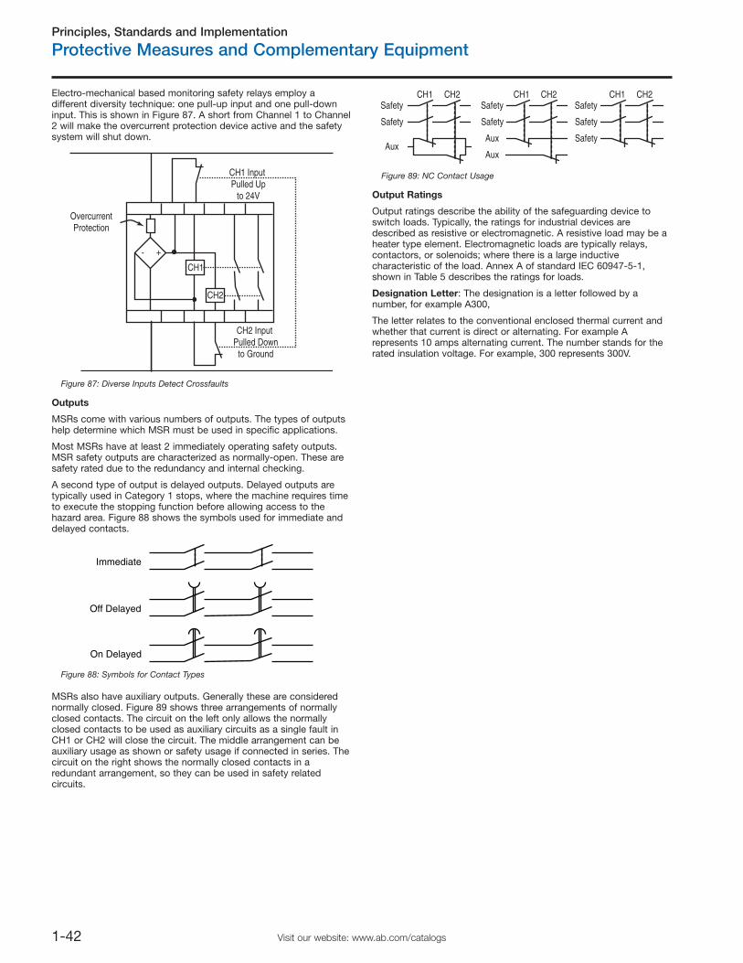
Principles, Standards and Implementation
Protective Measures and Complementary Equipment
1-42 Visit our website: www.ab.com/catalogs
Electro-mechanical based monitoring safety relays employ adifferent diversity technique: one pull-up input and one pull-downinput. This is shown in Figure 87. A short from Channel 1 to Channel2 will make the overcurrent protection device active and the safetysystem will shut down.
+-
CH1 Input Pulled Up
to 24V
CH2 Input Pulled Down
to Ground
OvercurrentProtection
CH1
CH2
Figure 87: Diverse Inputs Detect Crossfaults
Outputs
MSRs come with various numbers of outputs. The types of outputshelp determine which MSR must be used in specific applications.
Most MSRs have at least 2 immediately operating safety outputs.MSR safety outputs are characterized as normally-open. These aresafety rated due to the redundancy and internal checking.
A second type of output is delayed outputs. Delayed outputs aretypically used in Category 1 stops, where the machine requires timeto execute the stopping function before allowing access to thehazard area. Figure 88 shows the symbols used for immediate anddelayed contacts.
MSRs also have auxiliary outputs. Generally these are considerednormally closed. Figure 89 shows three arrangements of normallyclosed contacts. The circuit on the left only allows the normallyclosed contacts to be used as auxiliary circuits as a single fault inCH1 or CH2 will close the circuit. The middle arrangement can beauxiliary usage as shown or safety usage if connected in series. Thecircuit on the right shows the normally closed contacts in aredundant arrangement, so they can be used in safety relatedcircuits.
Safety
Safety
Aux
CH1 CH2Safety
Safety
Aux
Aux
CH1 CH2Safety
Safety
Safety
CH1 CH2
Figure 89: NC Contact Usage
Output Ratings
Output ratings describe the ability of the safeguarding device toswitch loads. Typically, the ratings for industrial devices aredescribed as resistive or electromagnetic. A resistive load may be aheater type element. Electromagnetic loads are typically relays,contactors, or solenoids; where there is a large inductivecharacteristic of the load. Annex A of standard IEC 60947-5-1,shown in Table 5 describes the ratings for loads.
Designation Letter: The designation is a letter followed by anumber, for example A300,
The letter relates to the conventional enclosed thermal current andwhether that current is direct or alternating. For example Arepresents 10 amps alternating current. The number stands for therated insulation voltage. For example, 300 represents 300V.
Off Delayed
On Delayed
Immediate
Figure 88: Symbols for Contact Types
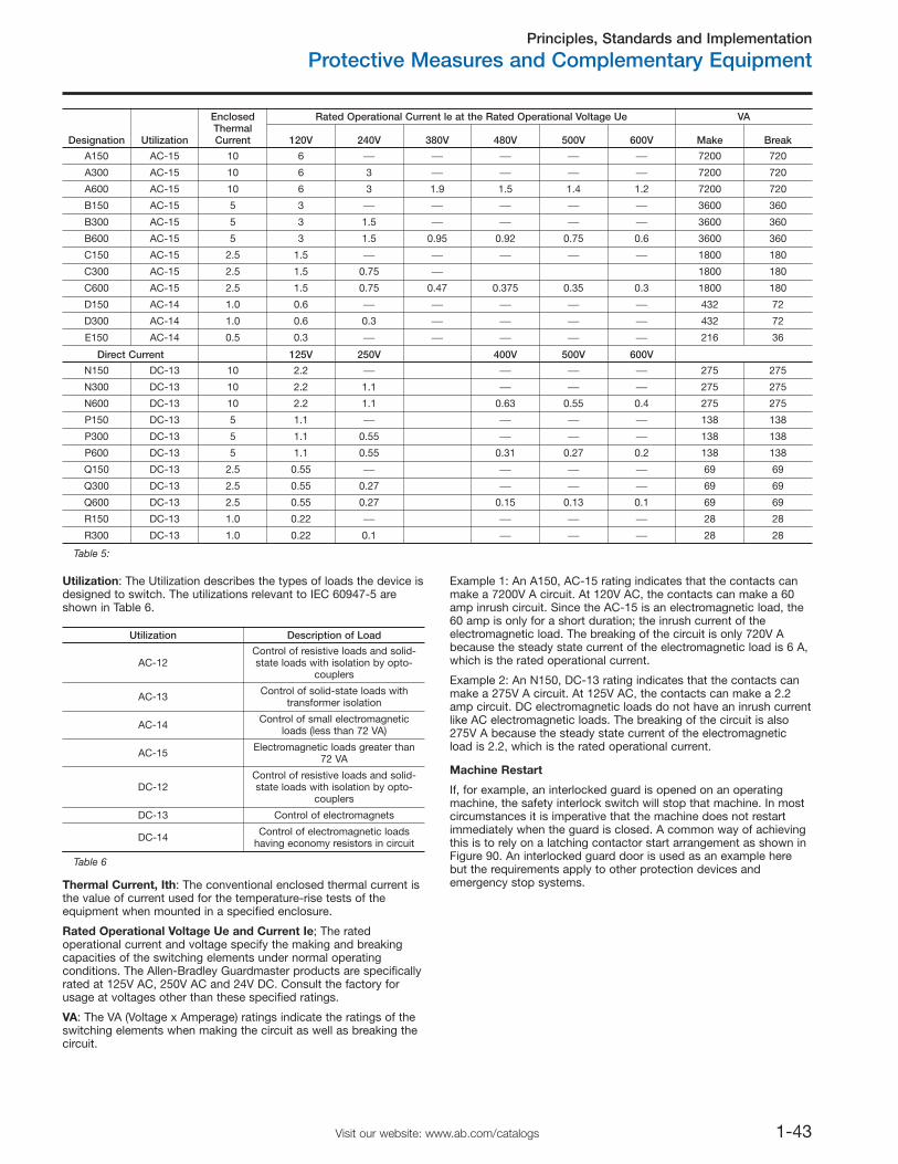
Principles, Standards and Implementation
Protective Measures and Complementary Equipment
1-43Visit our website: www.ab.com/catalogs
Designation Utilization
EnclosedThermalCurrent
Rated Operational Current le at the Rated Operational Voltage Ue VA
120V 240V 380V 480V 500V 600V Make Break
A150 AC-15 10 6 ⎯ ⎯ ⎯ ⎯ ⎯ 7200 720
A300 AC-15 10 6 3 ⎯ ⎯ ⎯ ⎯ 7200 720
A600 AC-15 10 6 3 1.9 1.5 1.4 1.2 7200 720
B150 AC-15 5 3 ⎯ ⎯ ⎯ ⎯ ⎯ 3600 360
B300 AC-15 5 3 1.5 ⎯ ⎯ ⎯ ⎯ 3600 360
B600 AC-15 5 3 1.5 0.95 0.92 0.75 0.6 3600 360
C150 AC-15 2.5 1.5 ⎯ ⎯ ⎯ ⎯ ⎯ 1800 180
C300 AC-15 2.5 1.5 0.75 ⎯ 1800 180
C600 AC-15 2.5 1.5 0.75 0.47 0.375 0.35 0.3 1800 180
D150 AC-14 1.0 0.6 ⎯ ⎯ ⎯ ⎯ ⎯ 432 72
D300 AC-14 1.0 0.6 0.3 ⎯ ⎯ ⎯ ⎯ 432 72
E150 AC-14 0.5 0.3 ⎯ ⎯ ⎯ ⎯ ⎯ 216 36
Direct Current 125V 250V 400V 500V 600V
N150 DC-13 10 2.2 ⎯ ⎯ ⎯ ⎯ 275 275
N300 DC-13 10 2.2 1.1 ⎯ ⎯ ⎯ 275 275
N600 DC-13 10 2.2 1.1 0.63 0.55 0.4 275 275
P150 DC-13 5 1.1 ⎯ ⎯ ⎯ ⎯ 138 138
P300 DC-13 5 1.1 0.55 ⎯ ⎯ ⎯ 138 138
P600 DC-13 5 1.1 0.55 0.31 0.27 0.2 138 138
Q150 DC-13 2.5 0.55 ⎯ ⎯ ⎯ ⎯ 69 69
Q300 DC-13 2.5 0.55 0.27 ⎯ ⎯ ⎯ 69 69
Q600 DC-13 2.5 0.55 0.27 0.15 0.13 0.1 69 69
R150 DC-13 1.0 0.22 ⎯ ⎯ ⎯ ⎯ 28 28
R300 DC-13 1.0 0.22 0.1 ⎯ ⎯ ⎯ 28 28
Table 5:
Utilization: The Utilization describes the types of loads the device isdesigned to switch. The utilizations relevant to IEC 60947-5 areshown in Table 6.
Utilization Description of Load
AC-12Control of resistive loads and solid-state loads with isolation by opto-
couplers
AC-13 Control of solid-state loads withtransformer isolation
AC-14 Control of small electromagneticloads (less than 72 VA)
AC-15 Electromagnetic loads greater than72 VA
DC-12Control of resistive loads and solid-state loads with isolation by opto-
couplers
DC-13 Control of electromagnets
DC-14 Control of electromagnetic loadshaving economy resistors in circuit
Table 6
Thermal Current, Ith: The conventional enclosed thermal current isthe value of current used for the temperature-rise tests of theequipment when mounted in a specified enclosure.
Rated Operational Voltage Ue and Current Ie; The ratedoperational current and voltage specify the making and breakingcapacities of the switching elements under normal operatingconditions. The Allen-Bradley Guardmaster products are specificallyrated at 125V AC, 250V AC and 24V DC. Consult the factory forusage at voltages other than these specified ratings.
VA: The VA (Voltage x Amperage) ratings indicate the ratings of theswitching elements when making the circuit as well as breaking thecircuit.
Example 1: An A150, AC-15 rating indicates that the contacts canmake a 7200V A circuit. At 120V AC, the contacts can make a 60amp inrush circuit. Since the AC-15 is an electromagnetic load, the60 amp is only for a short duration; the inrush current of theelectromagnetic load. The breaking of the circuit is only 720V Abecause the steady state current of the electromagnetic load is 6 A,which is the rated operational current.
Example 2: An N150, DC-13 rating indicates that the contacts canmake a 275V A circuit. At 125V AC, the contacts can make a 2.2amp circuit. DC electromagnetic loads do not have an inrush currentlike AC electromagnetic loads. The breaking of the circuit is also275V A because the steady state current of the electromagneticload is 2.2, which is the rated operational current.
Machine Restart
If, for example, an interlocked guard is opened on an operatingmachine, the safety interlock switch will stop that machine. In mostcircumstances it is imperative that the machine does not restartimmediately when the guard is closed. A common way of achievingthis is to rely on a latching contactor start arrangement as shown inFigure 90. An interlocked guard door is used as an example herebut the requirements apply to other protection devices andemergency stop systems.
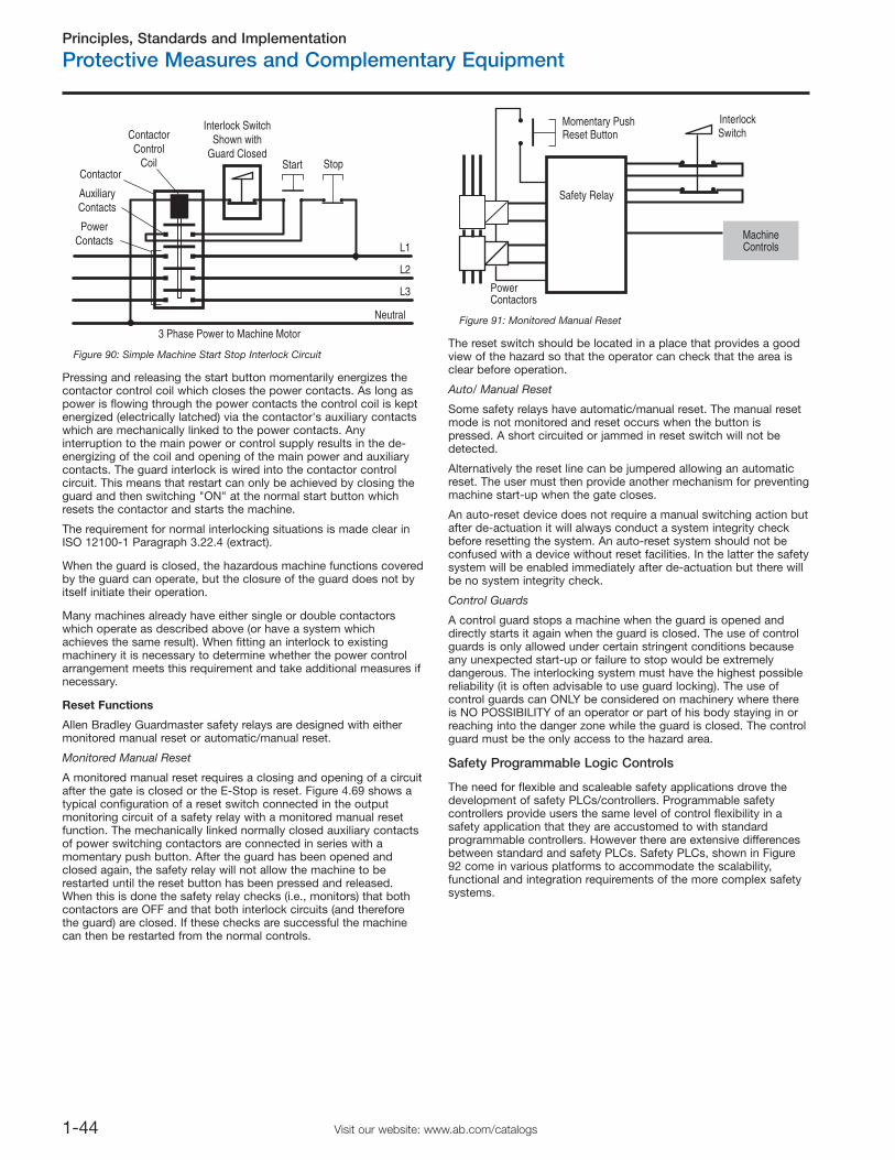
Principles, Standards and Implementation
Protective Measures and Complementary Equipment
1-44 Visit our website: www.ab.com/catalogs
3 Phase Power to Machine Motor
Neutral
ContactorControl
Coil
Interlock SwitchShown with
Guard ClosedStart Stop
AuxiliaryContacts
PowerContacts
L1
L3
L2
Contactor
Figure 90: Simple Machine Start Stop Interlock Circuit
Pressing and releasing the start button momentarily energizes thecontactor control coil which closes the power contacts. As long aspower is flowing through the power contacts the control coil is keptenergized (electrically latched) via the contactor's auxiliary contactswhich are mechanically linked to the power contacts. Anyinterruption to the main power or control supply results in the de-energizing of the coil and opening of the main power and auxiliarycontacts. The guard interlock is wired into the contactor controlcircuit. This means that restart can only be achieved by closing theguard and then switching "ON" at the normal start button whichresets the contactor and starts the machine.
The requirement for normal interlocking situations is made clear inISO 12100-1 Paragraph 3.22.4 (extract).
When the guard is closed, the hazardous machine functions coveredby the guard can operate, but the closure of the guard does not byitself initiate their operation.
Many machines already have either single or double contactorswhich operate as described above (or have a system whichachieves the same result). When fitting an interlock to existingmachinery it is necessary to determine whether the power controlarrangement meets this requirement and take additional measures ifnecessary.
Reset Functions
Allen Bradley Guardmaster safety relays are designed with eithermonitored manual reset or automatic/manual reset.
Monitored Manual Reset
A monitored manual reset requires a closing and opening of a circuitafter the gate is closed or the E-Stop is reset. Figure 4.69 shows atypical configuration of a reset switch connected in the outputmonitoring circuit of a safety relay with a monitored manual resetfunction. The mechanically linked normally closed auxiliary contactsof power switching contactors are connected in series with amomentary push button. After the guard has been opened andclosed again, the safety relay will not allow the machine to berestarted until the reset button has been pressed and released.When this is done the safety relay checks (i.e., monitors) that bothcontactors are OFF and that both interlock circuits (and thereforethe guard) are closed. If these checks are successful the machinecan then be restarted from the normal controls.
MachineControls
InterlockSwitch
PowerContactors
Safety Relay
Momentary PushReset Button
Figure 91: Monitored Manual Reset
The reset switch should be located in a place that provides a goodview of the hazard so that the operator can check that the area isclear before operation.
Auto/ Manual Reset
Some safety relays have automatic/manual reset. The manual resetmode is not monitored and reset occurs when the button ispressed. A short circuited or jammed in reset switch will not bedetected.
Alternatively the reset line can be jumpered allowing an automaticreset. The user must then provide another mechanism for preventingmachine start-up when the gate closes.
An auto-reset device does not require a manual switching action butafter de-actuation it will always conduct a system integrity checkbefore resetting the system. An auto-reset system should not beconfused with a device without reset facilities. In the latter the safetysystem will be enabled immediately after de-actuation but there willbe no system integrity check.
Control Guards
A control guard stops a machine when the guard is opened anddirectly starts it again when the guard is closed. The use of controlguards is only allowed under certain stringent conditions becauseany unexpected start-up or failure to stop would be extremelydangerous. The interlocking system must have the highest possiblereliability (it is often advisable to use guard locking). The use ofcontrol guards can ONLY be considered on machinery where thereis NO POSSIBILITY of an operator or part of his body staying in orreaching into the danger zone while the guard is closed. The controlguard must be the only access to the hazard area.
Safety Programmable Logic Controls
The need for flexible and scaleable safety applications drove thedevelopment of safety PLCs/controllers. Programmable safetycontrollers provide users the same level of control flexibility in asafety application that they are accustomed to with standardprogrammable controllers. However there are extensive differencesbetween standard and safety PLCs. Safety PLCs, shown in Figure92 come in various platforms to accommodate the scalability,functional and integration requirements of the more complex safetysystems.
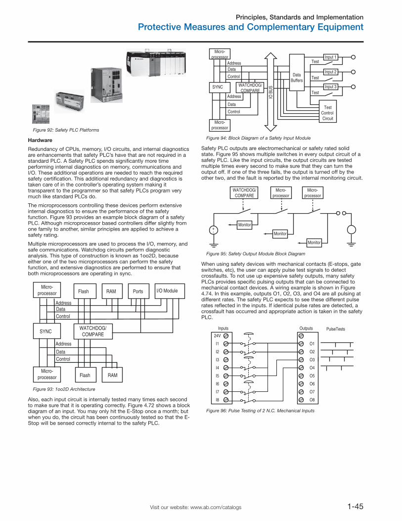
Principles, Standards and Implementation
Protective Measures and Complementary Equipment
1-45Visit our website: www.ab.com/catalogs
Figure 92: Safety PLC Platforms
Hardware
Redundancy of CPUs, memory, I/O circuits, and internal diagnosticsare enhancements that safety PLC’s have that are not required in astandard PLC. A Safety PLC spends significantly more timeperforming internal diagnostics on memory, communications andI/O. These additional operations are needed to reach the requiredsafety certification. This additional redundancy and diagnostics istaken care of in the controller’s operating system making ittransparent to the programmer so that safety PLCs program verymuch like standard PLCs do.
The microprocessors controlling these devices perform extensiveinternal diagnostics to ensure the performance of the safetyfunction. Figure 93 provides an example block diagram of a safetyPLC. Although microprocessor based controllers differ slightly fromone family to another, similar principles are applied to achieve asafety rating.
Multiple microprocessors are used to process the I/O, memory, andsafe communications. Watchdog circuits perform diagnosticanalysis. This type of construction is known as 1oo2D, becauseeither one of the two microprocessors can perform the safetyfunction, and extensive diagnostics are performed to ensure thatboth microprocessors are operating in sync.
AddressDataControl
Address
DataControl
Micro-processor
Micro-processor
SYNCWATCHDOG/
COMPARE
Flash RAM I/O ModulePorts
Flash RAM
Figure 93: 1oo2D Architecture
Also, each input circuit is internally tested many times each secondto make sure that it is operating correctly. Figure 4.72 shows a blockdiagram of an input. You may only hit the E-Stop once a month; butwhen you do, the circuit has been continuously tested so that the E-Stop will be sensed correctly internal to the safety PLC.
AddressData
Control
Address
Data
Control
Micro-processor
Micro-processor
DataBuffers
TestControl Circuit
SYNC
Input 1Test
Test
Test
WATCHDOG/COMPARE
Input 2
Input 3
IO B
US
Figure 94: Block Diagram of a Safety Input Module
Safety PLC outputs are electromechanical or safety rated solidstate. Figure 95 shows multiple switches in every output circuit of asafety PLC. Like the input circuits, the output circuits are testedmultiple times every second to make sure that they can turn theoutput off. If one of the three fails, the output is turned off by theother two, and the fault is reported by the internal monitoring circuit.
Micro-processor
Monitor
Monitor
Monitor
Micro-processor
WATCHDOG/COMPARE
+-
Figure 95: Safety Output Module Block Diagram
When using safety devices with mechanical contacts (E-stops, gateswitches, etc), the user can apply pulse test signals to detectcrossfaults. To not use up expensive safety outputs, many safetyPLCs provides specific pulsing outputs that can be connected tomechanical contact devices. A wiring example is shown in Figure4.74. In this example, outputs O1, O2, O3, and O4 are all pulsing atdifferent rates. The safety PLC expects to see these different pulserates reflected in the inputs. If identical pulse rates are detected, acrossfault has occurred and appropriate action is taken in the safetyPLC.
I1
24V
I3
I2
I5
I6
I7
I8
I4
O1
OutputsInputs PulseTests
O3
O2
O5
O6
O7
O8
O4
Figure 96: Pulse Testing of 2 N.C. Mechanical Inputs
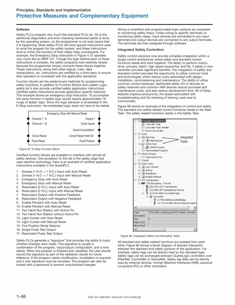
Principles, Standards and Implementation
Protective Measures and Complementary Equipment
1-46 Visit our website: www.ab.com/catalogs
Software
Safety PLCs program very much like standard PLCs do. All of theadditional diagnostics and error checking mentioned earlier is doneby the operating system, so the programmer is not even aware thatit is happening. Most safety PLCs will have special instructions usedto write the program for the safety system, and these instructionstend to mimic the function of their safety relay counterparts. Forexample, the Emergency Stop instruction in Figure 4.75 operatesvery much like an MSR 127. Though the logic behind each of theseinstructions is complex, the safety programs look relatively simplebecause the programmer simply connects these blocks together.These instructions, along with other logical, math, datamanipulation, etc. instructions are certified by a third party to ensuretheir operation is consistent with the applicable standards.
Function blocks are the predominant methods for programmingsafety functions. In addition to Function Blocks and Ladder Logic,safety plc's also provide certified safety application instructions.Certified safety instructions provide application specific behavior.This example shows an emergency stop instruction. To accomplishthe same function in ladder logic would require approximately 16rungs of ladder logic. Since the logic behavior is embedded in theE-Stop instruction, the embedded logic does not have to be tested.
Emergency Stop with Manual Reset
Channel 1 A Ouptut 1
Cycle Inputs
Inputs Inconsistent
Circuit Reset Held On
Fault Present
Channel 1 B
Circuit Reset
Fault Reset
Figure 97: E-Stop Function Block
Certified function blocks are available to interface with almost allsafety devices. One exception to this list is the safety edge thatuses resistive technology. Here is an example of certified applicationinstructions available in the GuardPLC.
1. Diverse (1 N.O. + 1 N.C.) Input with Auto Reset2. Diverse (1 N.O. + 1 N.C.) Input with Manual Reset3. Emergency Stop with Auto Reset4. Emergency Stop with Manual Reset5. Redundant (2 N.C.) Input with Auto Reset6. Redundant (2 N.C.) Input with Manual Reset7. Redundant Output with Positive Feedback8. Redundant Output with Negative Feedback9. Enable Pendant with Auto Reset10. Enable Pendant with Manual Reset11. Two Hand Run Station with Active Pin12. Two Hand Run Station without Active Pin13. Light Curtain with Auto Reset14. Light Curtain with Manual Reset15. Five Position Mode Selector16. Single Pulse Test Output17. Redundant Pulse Test Output
Safety PLCs generate a “signature” that provides the ability to trackwhether changes were made. This signature is usually acombination of the program, input/output configuration, and a timestamp. When the program is finalized and validated, the user shouldrecord this signature as part of the validation results for futurereference. If the program needs modification, revalidation is requiredand a new signature must be recorded. The program can also belocked with a password to prevent unauthorized changes.
Wiring is simplified with programmable logic systems as comparedto monitoring safety relays. Unlike wiring to specific terminals onmonitoring safety relays, input devices are connected to any inputterminals and output devices are connected to any output terminals.The terminals are then assigned through software.
Integrated Safety Controllers
Safety control solutions now provide complete integration within asingle control architecture where safety and standard controlfunctions reside and work together. The ability to perform motion,drive, process, batch, high speed sequential, and SIL 3 safety in onecontroller provides significant benefits. The integration of safety andstandard control provides the opportunity to utilize common toolsand technologies which reduce costs associated with design,installation, commissioning and maintenance. The ability to utilizecommon control hardware, distributed safety I/O or devices onsafety networks and common HMI devices reduce purchase andmaintenance costs, and also reduce development time. All of thesefeatures improve productivity, the speed associated withtroubleshooting and the lowering of training costs due tocommonality.
Figure 98 shows an example of the integration of control and safety.The standard non-safety related control functions reside in the MainTask. The safety related functions reside in the Safety Task.
IntegratedTasks
Figure 98: Integrated Safety and Nonsafety Tasks
All standard and safety related functions are isolated from eachother. Figure 99 shows a block diagram of allowed interactionbetween the standard and safety portions of the application. Forexample, safety tags can be directly read by the standard logic.Safety tags can be exchanged between GuardLogix controllers overEtherNet, ControlNet or DeviceNet. Safety tag data can be directlyread by external devices, Human Machine Interfaces (HMI), personalcomputers (PC) or other controllers.
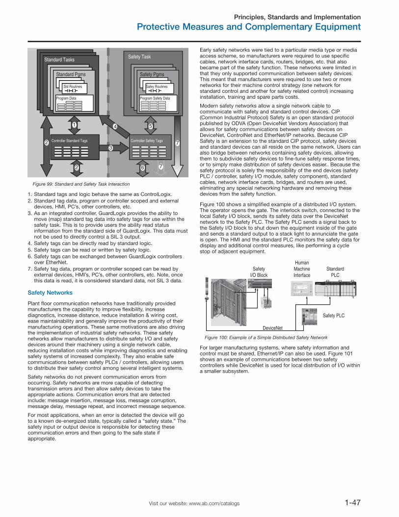
Principles, Standards and Implementation
Protective Measures and Complementary Equipment
1-47Visit our website: www.ab.com/catalogs
7
Standard Tasks
Standard Pgms
Std Routines
Program Data
Safety Task
Safety Pgms
Safey Routines
Program Safety Data
Controller Standard Tags Controller Safety Tags
Standard Tasks
Standard Pgms
Std Routines
Program Data
Controller Standard Tags
2
2
6
11 4
3
51
7
Figure 99: Standard and Safety Task Interaction
1. Standard tags and logic behave the same as ControlLogix.2. Standard tag data, program or controller scoped and external
devices, HMI, PC’s, other controllers, etc.3. As an integrated controller, GuardLogix provides the ability to
move (map) standard tag data into safety tags for use within thesafety task. This is to provide users the ability read statusinformation from the standard side of GuardLogix. This data mustnot be used to directly control a SIL 3 output.
4. Safety tags can be directly read by standard logic.5. Safety tags can be read or written by safety logic.6. Safety tags can be exchanged between GuardLogix controllers
over EtherNet.7. Safety tag data, program or controller scoped can be read by
external devices, HMI’s, PC’s, other controllers, etc. Note, oncethis data is read, it is considered standard data, not SIL 3 data.
Safety Networks
Plant floor communication networks have traditionally providedmanufacturers the capability to improve flexibility, increasediagnostics, increase distance, reduce installation & wiring cost,ease maintainability and generally improve the productivity of theirmanufacturing operations. These same motivations are also drivingthe implementation of industrial safety networks. These safetynetworks allow manufacturers to distribute safety I/O and safetydevices around their machinery using a single network cable,reducing installation costs while improving diagnostics and enablingsafety systems of increased complexity. They also enable safecommunications between safety PLCs / controllers, allowing usersto distribute their safety control among several intelligent systems.
Safety networks do not prevent communication errors fromoccurring. Safety networks are more capable of detectingtransmission errors and then allow safety devices to take theappropriate actions. Communication errors that are detectedinclude: message insertion, message loss, message corruption,message delay, message repeat, and incorrect message sequence.
For most applications, when an error is detected the device will goto a known de-energized state, typically called a “safety state.” Thesafety input or output device is responsible for detecting thesecommunication errors and then going to the safe state ifappropriate.
Early safety networks were tied to a particular media type or mediaaccess scheme, so manufacturers were required to use specificcables, network interface cards, routers, bridges, etc. that alsobecame part of the safety function. These networks were limited inthat they only supported communication between safety devices.This meant that manufacturers were required to use two or morenetworks for their machine control strategy (one network forstandard control and another for safety related control) increasinginstallation, training and spare parts costs.
Modern safety networks allow a single network cable tocommunicate with safety and standard control devices. CIP(Common Industrial Protocol) Safety is an open standard protocolpublished by ODVA (Open DeviceNet Vendors Association) thatallows for safety communications between safety devices onDeviceNet, ControlNet and EtherNet/IP networks. Because CIPSafety is an extension to the standard CIP protocol, safety devicesand standard devices can all reside on the same network. Users canalso bridge between networks containing safety devices, allowingthem to subdivide safety devices to fine-tune safety response times,or to simply make distribution of safety devices easier.. Because thesafety protocol is solely the responsibility of the end devices (safetyPLC / controller, safety I/O module, safety component), standardcables, network interface cards, bridges, and routers are used,eliminating any special networking hardware and removing thesedevices from the safety function.
Figure 100 shows a simplified example of a distributed I/O system.The operator opens the gate. The interlock switch, connected to thelocal Safety I/O block, sends its safety data over the DeviceNetnetwork to the Safety PLC. The Safety PLC sends a signal back tothe Safety I/O block to shut down the equipment inside of the gateand sends a standard output to a stack light to annunciate the gateis open. The HMI and the standard PLC monitors the safety data fordisplay and additional control measures, like performing a cyclestop of adjacent equipment.
StandardPLC
Safety PLC
DeviceNet
SafetyI/O Block
HumanMachineInterface
Figure 100: Example of a Simple Distributed Safety Network
For larger manufacturing systems, where safety information andcontrol must be shared, Ethernet/IP can also be used. Figure 101shows an example of communications between two safetycontrollers while DeviceNet is used for local distribution of I/O withina smaller subsystem.
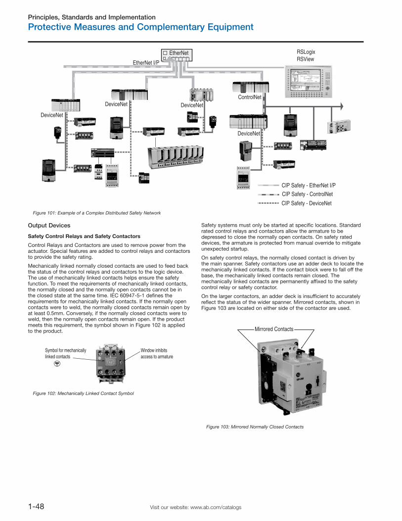
Principles, Standards and Implementation
Protective Measures and Complementary Equipment
1-48 Visit our website: www.ab.com/catalogs
Output Devices
Safety Control Relays and Safety Contactors
Control Relays and Contactors are used to remove power from theactuator. Special features are added to control relays and contactorsto provide the safety rating.
Mechanically linked normally closed contacts are used to feed backthe status of the control relays and contactors to the logic device.The use of mechanically linked contacts helps ensure the safetyfunction. To meet the requirements of mechanically linked contacts,the normally closed and the normally open contacts cannot be inthe closed state at the same time. IEC 60947-5-1 defines therequirements for mechanically linked contacts. If the normally opencontacts were to weld, the normally closed contacts remain open byat least 0.5mm. Conversely, if the normally closed contacts were toweld, then the normally open contacts remain open. If the productmeets this requirement, the symbol shown in Figure 102 is appliedto the product.
Safety systems must only be started at specific locations. Standardrated control relays and contactors allow the armature to bedepressed to close the normally open contacts. On safety rateddevices, the armature is protected from manual override to mitigateunexpected startup.
On safety control relays, the normally closed contact is driven bythe main spanner. Safety contactors use an adder deck to locate themechanically linked contacts. If the contact block were to fall off thebase, the mechanically linked contacts remain closed. Themechanically linked contacts are permanently affixed to the safetycontrol relay or safety contactor.
On the larger contactors, an adder deck is insufficient to accuratelyreflect the status of the wider spanner. Mirrored contacts, shown inFigure 103 are located on either side of the contactor are used.
RSLogixRSView
ControlNet
CIP Safety - ControlNet
CIP Safety - DeviceNet
EtherNet I/P
CIP Safety - EtherNet I/P
DeviceNet
DeviceNet
DeviceNet
DeviceNet
EtherNet
Figure 101: Example of a Complex Distributed Safety Network
Window inhibitsaccess to armature
Symbol for mechanically linked contacts
Figure 102: Mechanically Linked Contact Symbol
Mirrored Contacts
Figure 103: Mirrored Normally Closed Contacts
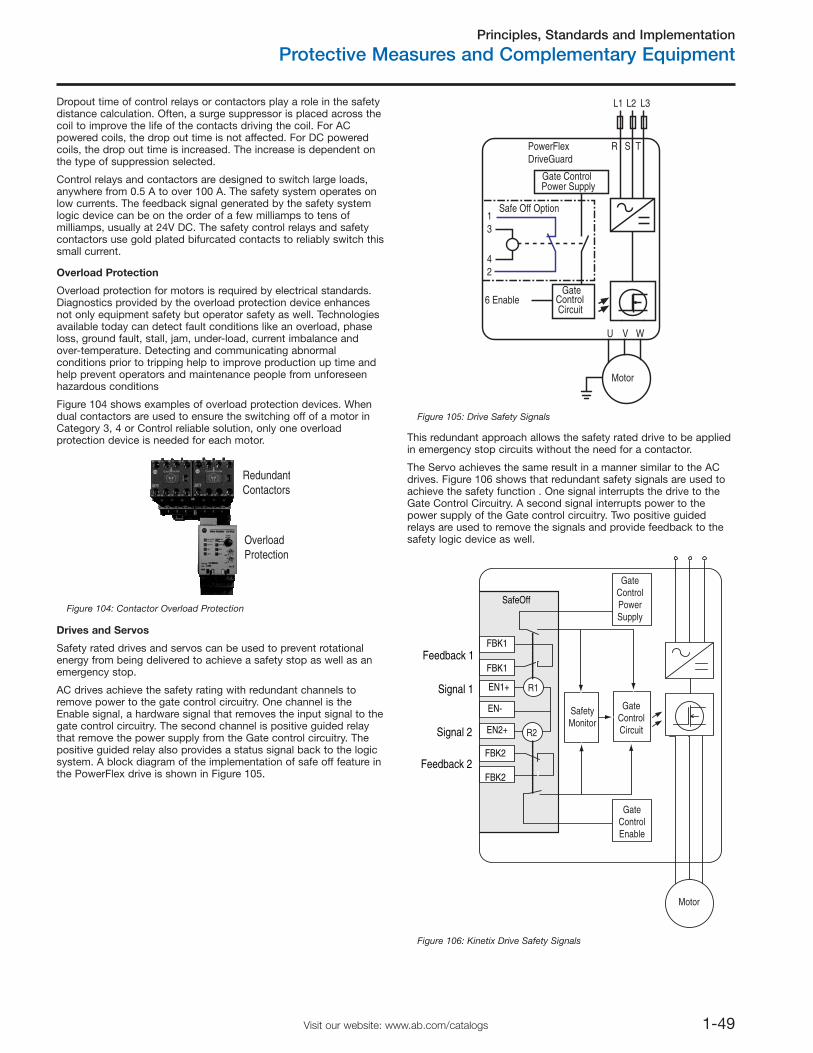
Principles, Standards and Implementation
Protective Measures and Complementary Equipment
1-49Visit our website: www.ab.com/catalogs
Dropout time of control relays or contactors play a role in the safetydistance calculation. Often, a surge suppressor is placed across thecoil to improve the life of the contacts driving the coil. For ACpowered coils, the drop out time is not affected. For DC poweredcoils, the drop out time is increased. The increase is dependent onthe type of suppression selected.
Control relays and contactors are designed to switch large loads,anywhere from 0.5 A to over 100 A. The safety system operates onlow currents. The feedback signal generated by the safety systemlogic device can be on the order of a few milliamps to tens ofmilliamps, usually at 24V DC. The safety control relays and safetycontactors use gold plated bifurcated contacts to reliably switch thissmall current.
Overload Protection
Overload protection for motors is required by electrical standards.Diagnostics provided by the overload protection device enhancesnot only equipment safety but operator safety as well. Technologiesavailable today can detect fault conditions like an overload, phaseloss, ground fault, stall, jam, under-load, current imbalance andover-temperature. Detecting and communicating abnormalconditions prior to tripping help to improve production up time andhelp prevent operators and maintenance people from unforeseenhazardous conditions
Figure 104 shows examples of overload protection devices. Whendual contactors are used to ensure the switching off of a motor inCategory 3, 4 or Control reliable solution, only one overloadprotection device is needed for each motor.
Drives and Servos
Safety rated drives and servos can be used to prevent rotationalenergy from being delivered to achieve a safety stop as well as anemergency stop.
AC drives achieve the safety rating with redundant channels toremove power to the gate control circuitry. One channel is theEnable signal, a hardware signal that removes the input signal to thegate control circuitry. The second channel is positive guided relaythat remove the power supply from the Gate control circuitry. Thepositive guided relay also provides a status signal back to the logicsystem. A block diagram of the implementation of safe off feature inthe PowerFlex drive is shown in Figure 105.
Motor
L1 L2 L3
R TS
U WV
42
31
Safe Off Option
6 Enable
PowerFlexDriveGuard
GateControlCircuit
Gate ControlPower Supply
Figure 105: Drive Safety Signals
This redundant approach allows the safety rated drive to be appliedin emergency stop circuits without the need for a contactor.
The Servo achieves the same result in a manner similar to the ACdrives. Figure 106 shows that redundant safety signals are used toachieve the safety function . One signal interrupts the drive to theGate Control Circuitry. A second signal interrupts power to thepower supply of the Gate control circuitry. Two positive guidedrelays are used to remove the signals and provide feedback to thesafety logic device as well.
RedundantContactors
OverloadProtection
Figure 104: Contactor Overload Protection
Motor
R1
R2
GateControlPowerSupply
SafetyMonitor
EN1+
EN-
EN2+
FBK1
FBK1
FBK2
FBK2
GateControlCircuit
GateControlEnable
SafeOff
Feedback 1
Feedback 2
Signal 1
Signal 2
Figure 106: Kinetix Drive Safety Signals
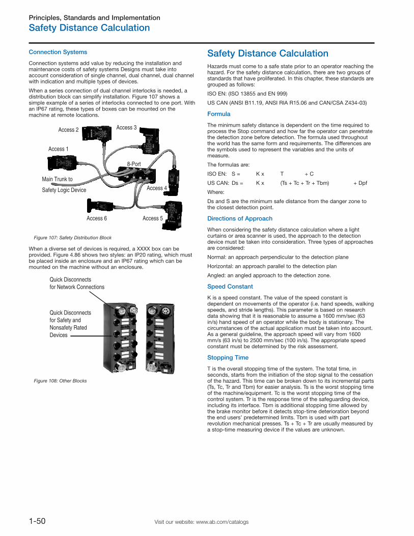
Principles, Standards and Implementation
Safety Distance Calculation
1-50 Visit our website: www.ab.com/catalogs
When a diverse set of devices is required, a XXXX box can beprovided. Figure 4.86 shows two styles: an IP20 rating, which mustbe placed inside an enclosure and an IP67 rating which can bemounted on the machine without an enclosure.
Safety Distance CalculationHazards must come to a safe state prior to an operator reaching thehazard. For the safety distance calculation, there are two groups ofstandards that have proliferated. In this chapter, these standards aregrouped as follows:
ISO EN: (ISO 13855 and EN 999)
US CAN (ANSI B11.19, ANSI RIA R15.06 and CAN/CSA Z434-03)
Formula
The minimum safety distance is dependent on the time required toprocess the Stop command and how far the operator can penetratethe detection zone before detection. The formula used throughoutthe world has the same form and requirements. The differences arethe symbols used to represent the variables and the units ofmeasure.
The formulas are:
ISO EN: S = K x T + C
US CAN: Ds = K x (Ts + Tc + Tr + Tbm) + Dpf
Where:
Ds and S are the minimum safe distance from the danger zone tothe closest detection point.
Directions of Approach
When considering the safety distance calculation where a lightcurtains or area scanner is used, the approach to the detectiondevice must be taken into consideration. Three types of approachesare considered:
Normal: an approach perpendicular to the detection plane
Horizontal: an approach parallel to the detection plan
Angled: an angled approach to the detection zone.
Speed Constant
K is a speed constant. The value of the speed constant isdependent on movements of the operator (i.e. hand speeds, walkingspeeds, and stride lengths). This parameter is based on researchdata showing that it is reasonable to assume a 1600 mm/sec (63in/s) hand speed of an operator while the body is stationary. Thecircumstances of the actual application must be taken into account.As a general guideline, the approach speed will vary from 1600mm/s (63 in/s) to 2500 mm/sec (100 in/s). The appropriate speedconstant must be determined by the risk assessment.
Stopping Time
T is the overall stopping time of the system. The total time, inseconds, starts from the initiation of the stop signal to the cessationof the hazard. This time can be broken down to its incremental parts(Ts, Tc, Tr and Tbm) for easier analysis. Ts is the worst stopping timeof the machine/equipment. Tc is the worst stopping time of thecontrol system. Tr is the response time of the safeguarding device,including its interface. Tbm is additional stopping time allowed bythe brake monitor before it detects stop-time deterioration beyondthe end users’ predetermined limits. Tbm is used with partrevolution mechanical presses. Ts + Tc + Tr are usually measured bya stop-time measuring device if the values are unknown.
Connection Systems
Connection systems add value by reducing the installation andmaintenance costs of safety systems Designs must take intoaccount consideration of single channel, dual channel, dual channelwith indication and multiple types of devices.
When a series connection of dual channel interlocks is needed, adistribution block can simplify installation. Figure 107 shows asimple example of a series of interlocks connected to one port. Withan IP67 rating, these types of boxes can be mounted on themachine at remote locations.
Main Trunk to
Safety Logic Device
Access 1
Access 2 Access 3
Access 4
Access 5Access 6
8-Port
Figure 107: Safety Distribution Block
Quick Disconnectsfor Safety andNonsafety RatedDevices
Quick Disconnectsfor Network Connections
Figure 108: Other Blocks
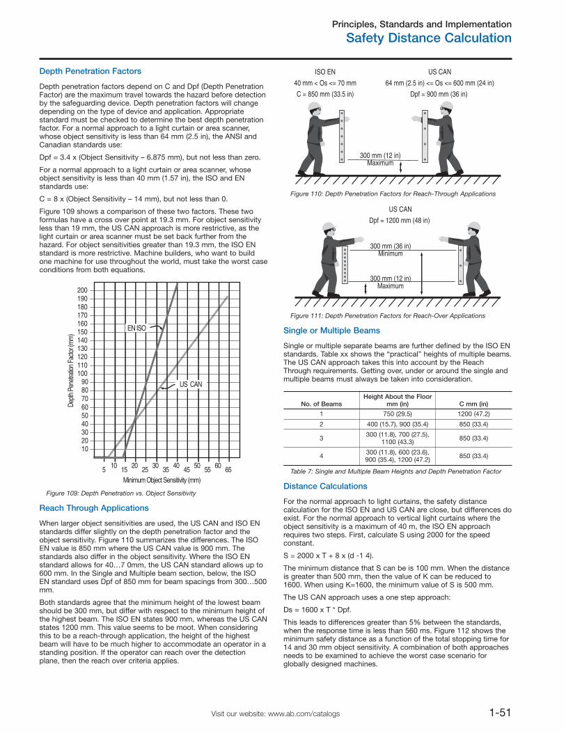
Principles, Standards and Implementation
Safety Distance Calculation
1-51Visit our website: www.ab.com/catalogs
Depth Penetration Factors
Depth penetration factors depend on C and Dpf (Depth PenetrationFactor) are the maximum travel towards the hazard before detectionby the safeguarding device. Depth penetration factors will changedepending on the type of device and application. Appropriatestandard must be checked to determine the best depth penetrationfactor. For a normal approach to a light curtain or area scanner,whose object sensitivity is less than 64 mm (2.5 in), the ANSI andCanadian standards use:
Dpf = 3.4 x (Object Sensitivity – 6.875 mm), but not less than zero.
For a normal approach to a light curtain or area scanner, whoseobject sensitivity is less than 40 mm (1.57 in), the ISO and ENstandards use:
C = 8 x (Object Sensitivity – 14 mm), but not less than 0.
Figure 109 shows a comparison of these two factors. These twoformulas have a cross over point at 19.3 mm. For object sensitivityless than 19 mm, the US CAN approach is more restrictive, as thelight curtain or area scanner must be set back further from thehazard. For object sensitivities greater than 19.3 mm, the ISO ENstandard is more restrictive. Machine builders, who want to buildone machine for use throughout the world, must take the worst caseconditions from both equations.
10
5 10 15 20 25 30 35Minimum Object Sensitivity (mm)
Dept
h Pe
netra
tion
Facto
r (m
m)
40 45 50 55 60 65
2030405060708090
100
120110
130140150160170180190200
US CAN
EN ISO
Figure 109: Depth Penetration vs. Object Sensitivity
Reach Through Applications
When larger object sensitivities are used, the US CAN and ISO ENstandards differ slightly on the depth penetration factor and theobject sensitivity. Figure 110 summarizes the differences. The ISOEN value is 850 mm where the US CAN value is 900 mm. Thestandards also differ in the object sensitivity. Where the ISO ENstandard allows for 40…7 0mm, the US CAN standard allows up to600 mm. In the Single and Multiple beam section, below, the ISOEN standard uses Dpf of 850 mm for beam spacings from 300…500mm.
Both standards agree that the minimum height of the lowest beamshould be 300 mm, but differ with respect to the minimum height ofthe highest beam. The ISO EN states 900 mm, whereas the US CANstates 1200 mm. This value seems to be moot. When consideringthis to be a reach-through application, the height of the highestbeam will have to be much higher to accommodate an operator in astanding position. If the operator can reach over the detectionplane, then the reach over criteria applies.
300 mm (12 in)Maximum
US CAN
64 mm (2.5 in) <= Os <= 600 mm (24 in)
Dpf = 900 mm (36 in)
ISO EN
40 mm < Os <= 70 mm
C = 850 mm (33.5 in)
Figure 110: Depth Penetration Factors for Reach-Through Applications
300 mm (12 in)Maximum
300 mm (36 in)Minimum
US CAN
Dpf = 1200 mm (48 in)
Figure 111: Depth Penetration Factors for Reach-Over Applications
Single or Multiple Beams
Single or multiple separate beams are further defined by the ISO ENstandards. Table xx shows the “practical” heights of multiple beams.The US CAN approach takes this into account by the ReachThrough requirements. Getting over, under or around the single andmultiple beams must always be taken into consideration.
No. of BeamsHeight About the Floor
mm (in) C mm (in)
1 750 (29.5) 1200 (47.2)
2 400 (15.7), 900 (35.4) 850 (33.4)
3 300 (11.8), 700 (27.5),1100 (43.3) 850 (33.4)
4 300 (11.8), 600 (23.6),900 (35.4), 1200 (47.2) 850 (33.4)
Table 7: Single and Multiple Beam Heights and Depth Penetration Factor
Distance Calculations
For the normal approach to light curtains, the safety distancecalculation for the ISO EN and US CAN are close, but differences doexist. For the normal approach to vertical light curtains where theobject sensitivity is a maximum of 40 m, the ISO EN approachrequires two steps. First, calculate S using 2000 for the speedconstant.
S = 2000 x T + 8 x (d -1 4).
The minimum distance that S can be is 100 mm. When the distanceis greater than 500 mm, then the value of K can be reduced to1600. When using K=1600, the minimum value of S is 500 mm.
The US CAN approach uses a one step approach:
Ds = 1600 x T * Dpf.
This leads to differences greater than 5% between the standards,when the response time is less than 560 ms. Figure 112 shows theminimum safety distance as a function of the total stopping time for14 and 30 mm object sensitivity. A combination of both approachesneeds to be examined to achieve the worst case scenario forglobally designed machines.
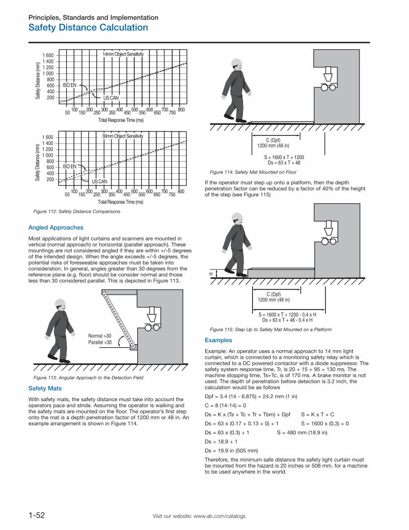
Principles, Standards and Implementation
Safety Distance Calculation
1-52 Visit our website: www.ab.com/catalogs
200
50 100 150 200 250 300 350Total Response Time (ms)
Safe
ty Di
stanc
e (m
m)
400 450 500 550 600 650 700 750 800
400600800
1 0001 2001 4001 600
200
50 100 150 200 250 300 350Total Response Time (ms)
Safe
ty Di
stanc
e (m
m)
400 450 500 550 600 650 700 750 800
400600800
1 0001 2001 4001 600
ISO EN
ISO EN
US CAN
US CAN
14mm Object Sensitivity
30mm Object Sensitivity
Figure 112: Safety Distance Comparisons
Angled Approaches
Most applications of light curtains and scanners are mounted invertical (normal approach) or horizontal (parallel approach). Thesemountings are not considered angled if they are within +/-5 degreesof the intended design. When the angle exceeds +/-5 degrees, thepotential risks of foreseeable approaches must be taken intoconsideration. In general, angles greater than 30 degrees from thereference plane (e.g. floor) should be consider normal and thoseless than 30 considered parallel. This is depicted in Figure 113.
Normal >30Parallel <30
Figure 113: Angular Approach to the Detection Field
Safety Mats
With safety mats, the safety distance must take into account theoperators pace and stride. Assuming the operator is walking andthe safety mats are mounted on the floor. The operator’s first steponto the mat is a depth penetration factor of 1200 mm or 48 in. Anexample arrangement is shown in Figure 114.
C (Dpf)1200 mm (48 in)
S = 1600 x T + 1200Ds = 63 x T + 48
Figure 114: Safety Mat Mounted on Floor
If the operator must step up onto a platform, then the depthpenetration factor can be reduced by a factor of 40% of the heightof the step (see Figure 115)
C (Dpf)1200 mm (48 in)
S = 1600 x T + 1200 - 0,4 x HDs = 63 x T + 48 - 0.4 x H
H
Figure 115: Step Up to Safety Mat Mounted on a Platform
Examples
Example: An operator uses a normal approach to 14 mm lightcurtain, which is connected to a monitoring safety relay which isconnected to a DC powered contactor with a diode suppressor. Thesafety system response time, Tr, is 20 + 15 + 95 = 130 ms. Themachine stopping time, Ts+Tc, is of 170 ms. A brake monitor is notused. The depth of penetration before detection is 3.2 inch, thecalculation would be as follows
Dpf = 3.4 (14 - 6.875) = 24.2 mm (1 in)
C = 8 (14-14) = 0
Ds = K x (Ts + Tc + Tr + Tbm) + Dpf S = K x T + C
Ds = 63 x (0.17 + 0.13 + 0) + 1 S = 1600 x (0,3) + 0
Ds = 63 x (0.3) + 1 S = 480 mm (18.9 in)
Ds = 18.9 + 1
Ds = 19.9 in (505 mm)
Therefore, the minimum safe distance the safety light curtain mustbe mounted from the hazard is 20 inches or 508 mm, for a machineto be used anywhere in the world.
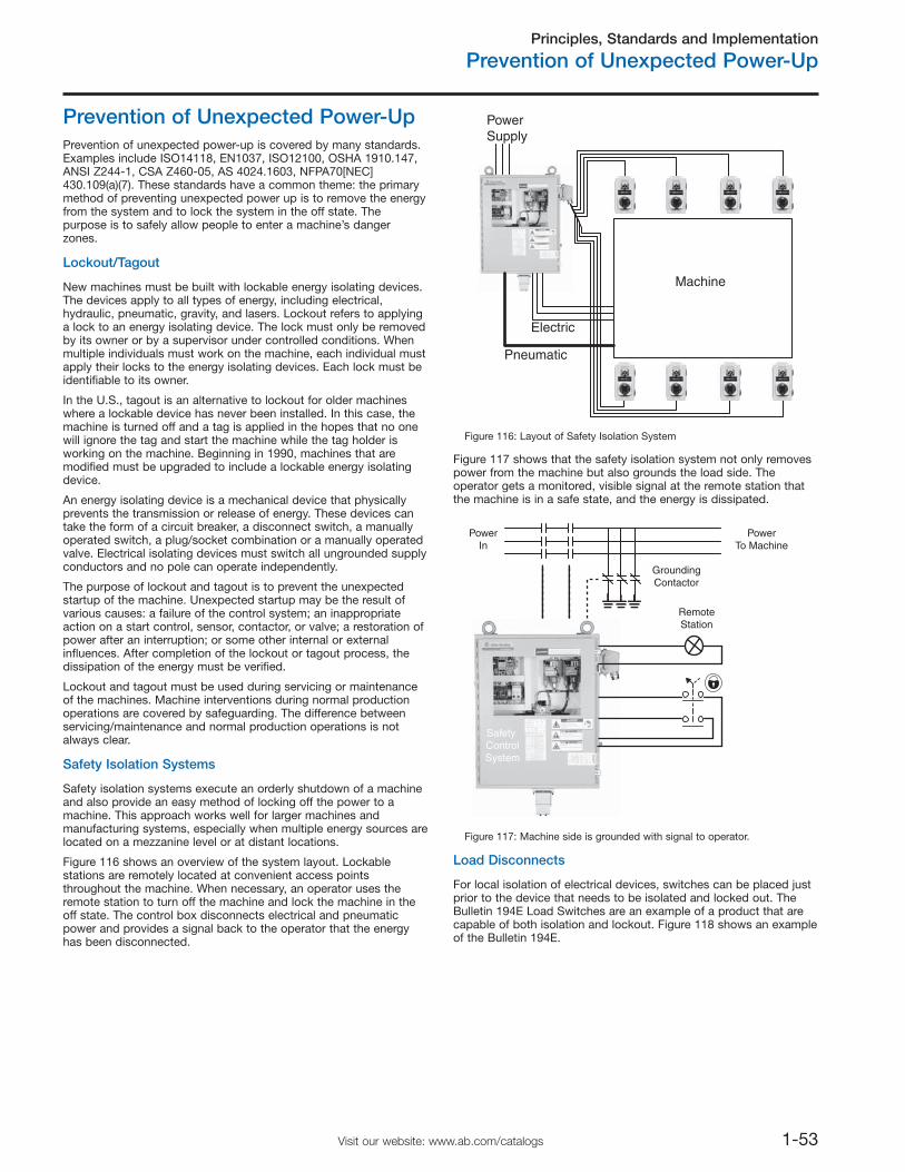
Principles, Standards and Implementation
Prevention of Unexpected Power-Up
1-53Visit our website: www.ab.com/catalogs
Prevention of Unexpected Power-UpPrevention of unexpected power-up is covered by many standards.Examples include ISO14118, EN1037, ISO12100, OSHA 1910.147,ANSI Z244-1, CSA Z460-05, AS 4024.1603, NFPA70[NEC]430.109(a)(7). These standards have a common theme: the primarymethod of preventing unexpected power up is to remove the energyfrom the system and to lock the system in the off state. Thepurpose is to safely allow people to enter a machine’s dangerzones.
Lockout/Tagout
New machines must be built with lockable energy isolating devices.The devices apply to all types of energy, including electrical,hydraulic, pneumatic, gravity, and lasers. Lockout refers to applyinga lock to an energy isolating device. The lock must only be removedby its owner or by a supervisor under controlled conditions. Whenmultiple individuals must work on the machine, each individual mustapply their locks to the energy isolating devices. Each lock must beidentifiable to its owner.
In the U.S., tagout is an alternative to lockout for older machineswhere a lockable device has never been installed. In this case, themachine is turned off and a tag is applied in the hopes that no onewill ignore the tag and start the machine while the tag holder isworking on the machine. Beginning in 1990, machines that aremodified must be upgraded to include a lockable energy isolatingdevice.
An energy isolating device is a mechanical device that physicallyprevents the transmission or release of energy. These devices cantake the form of a circuit breaker, a disconnect switch, a manuallyoperated switch, a plug/socket combination or a manually operatedvalve. Electrical isolating devices must switch all ungrounded supplyconductors and no pole can operate independently.
The purpose of lockout and tagout is to prevent the unexpectedstartup of the machine. Unexpected startup may be the result ofvarious causes: a failure of the control system; an inappropriateaction on a start control, sensor, contactor, or valve; a restoration ofpower after an interruption; or some other internal or externalinfluences. After completion of the lockout or tagout process, thedissipation of the energy must be verified.
Lockout and tagout must be used during servicing or maintenanceof the machines. Machine interventions during normal productionoperations are covered by safeguarding. The difference betweenservicing/maintenance and normal production operations is notalways clear.
Safety Isolation Systems
PowerSupply
Electric
Pneumatic
Machine
Figure 116: Layout of Safety Isolation System
Safety isolation systems execute an orderly shutdown of a machineand also provide an easy method of locking off the power to amachine. This approach works well for larger machines andmanufacturing systems, especially when multiple energy sources arelocated on a mezzanine level or at distant locations.
Figure 116 shows an overview of the system layout. Lockablestations are remotely located at convenient access pointsthroughout the machine. When necessary, an operator uses theremote station to turn off the machine and lock the machine in theoff state. The control box disconnects electrical and pneumaticpower and provides a signal back to the operator that the energyhas been disconnected.
Figure 117 shows that the safety isolation system not only removespower from the machine but also grounds the load side. Theoperator gets a monitored, visible signal at the remote station thatthe machine is in a safe state, and the energy is dissipated.
PowerIn
PowerTo Machine
Safety ControlSystem
RemoteStation
GroundingContactor
Figure 117: Machine side is grounded with signal to operator.
Load Disconnects
For local isolation of electrical devices, switches can be placed justprior to the device that needs to be isolated and locked out. TheBulletin 194E Load Switches are an example of a product that arecapable of both isolation and lockout. Figure 118 shows an exampleof the Bulletin 194E.
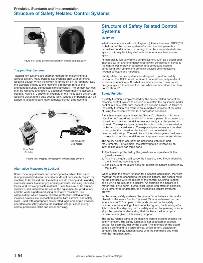
Principles, Standards and Implementation
Structure of Safety Related Control Systems
1-54 Visit our website: www.ab.com/catalogs
Trapped Key Systems
Trapped key systems are another method for implementing alockout system. Many trapped key systems start with an energyisolating device. When the switch is turned off by the “primary” key,the electrical energy to the machine is removed from all theungrounded supply conductors simultaneously. The primary key canthen be removed and taken to a location where machine access isneeded. Figure 119 shows an example of the most basic system, anisolating switch and a gate access lock. Various components can beadded to accommodate more complex lockout arrangements.
Alternative Measures to Lockout
Some minor adjustments and servicing tasks, which take placeduring normal production operations, do not necessarily require themachine to be locked out. Examples include loading and unloadingmaterials, minor tool changes and adjustments, servicing lubricationlevels, and removing waste material. These tasks must be routine,repetitive, and integral to the use of the equipment for production,and the work is performed using alternative measures, likesafeguarding, which provide effective protection. Safeguardingincludes devices like interlocked guards, light curtains, and safetymats. Used with appropriate safety rated logic and output devices,operators can safety access the machine danger zones duringnormal production tasks and minor servicing.
Structure of Safety Related ControlSystemsOverview
What is a safety related control system (often abbreviated SRCS)? Itis that part of the control system of a machine that prevents ahazardous condition from occurring. It can be a separate dedicatedsystem or it may be integrated with the normal machine controlsystem.
Its complexity will vary from a simple system, such as a guard doorinterlock switch and emergency stop switch connected in series tothe control coil of power contactor, to a compound systemcomprising both simple and complex devices communicatingthrough software and hardware.
Safety related control systems are designed to perform safetyfunctions. The SRCS must continue to operate correctly under allforeseeable conditions. So what is a safety function; how do wedesign a system to achieve this; and when we have done that, howdo we show it?
Safety Function
A safety function is implemented by the safety related parts of themachine control system to achieve or maintain the equipment undercontrol in a safe state with respect to a specific hazard. A failure ofthe safety function can result in an immediate increase of the risksof using the equipment; that is, a hazardous condition.
A machine must have at least one “hazard”, otherwise, it is not amachine. A “hazardous condition” is when a person is exposed to ahazard. A hazardous condition does not imply that the person isharmed. The exposed person may be able to able to acknowledgethe hazard and avoid injury. The exposed person may not be ableto recognize the hazard, or the hazard may be initiated byunexpected startup. The main task of the safety system designer isto prevent hazardous conditions and to prevent unexpected startup.
The safety function can often be described with multi-partrequirements. For example, the safety function initiated by aninterlocking guard has three parts:
1. The hazards protected by the guard cannot operate until theguard is closed;
2. Opening the guard will cause the hazard to stop if operational atthe time of the opening; and
3. The closure of the guard does not restart the hazard protected bythe guard.
When stating the safety function for a specific application, the word“hazard” must be changed to the specific hazard. The hazard mustnot be confused with the results of the hazard. Crushing, cutting,and burning are results of a hazard. An example of a hazard is amotor, ram, knife, torch, pump, laser, robot, end-effector, solenoid,valve, other type of actuator, or a mechanical hazard involvinggravity.
In discussing safety systems, the phrase “at or before a demand isplaced on the safety function” is used. What is a demand on thesafety function? Examples of demands placed on the safetyfunction are the opening of an interlocked guard, the breaking of alight curtain, the stepping onto a safety mat, or the pressing of an e-stop. An operator is demanding that the hazard either stop orremain de-energized if it is already stopped.
The safety related parts of the machine control system execute thesafety function. The safety function is not executed by a singledevice, for example, just by the guard. The interlock on the guardsends a command to a logic device, which in turn, disables anactuator. The safety function starts with the command and endswith the implementation.
Figure 118: Load switch with isolation and locking capability
Motor RatedController
Lockable SafetyGate Access
Figure 119: Trapped key isolation and lockable devices
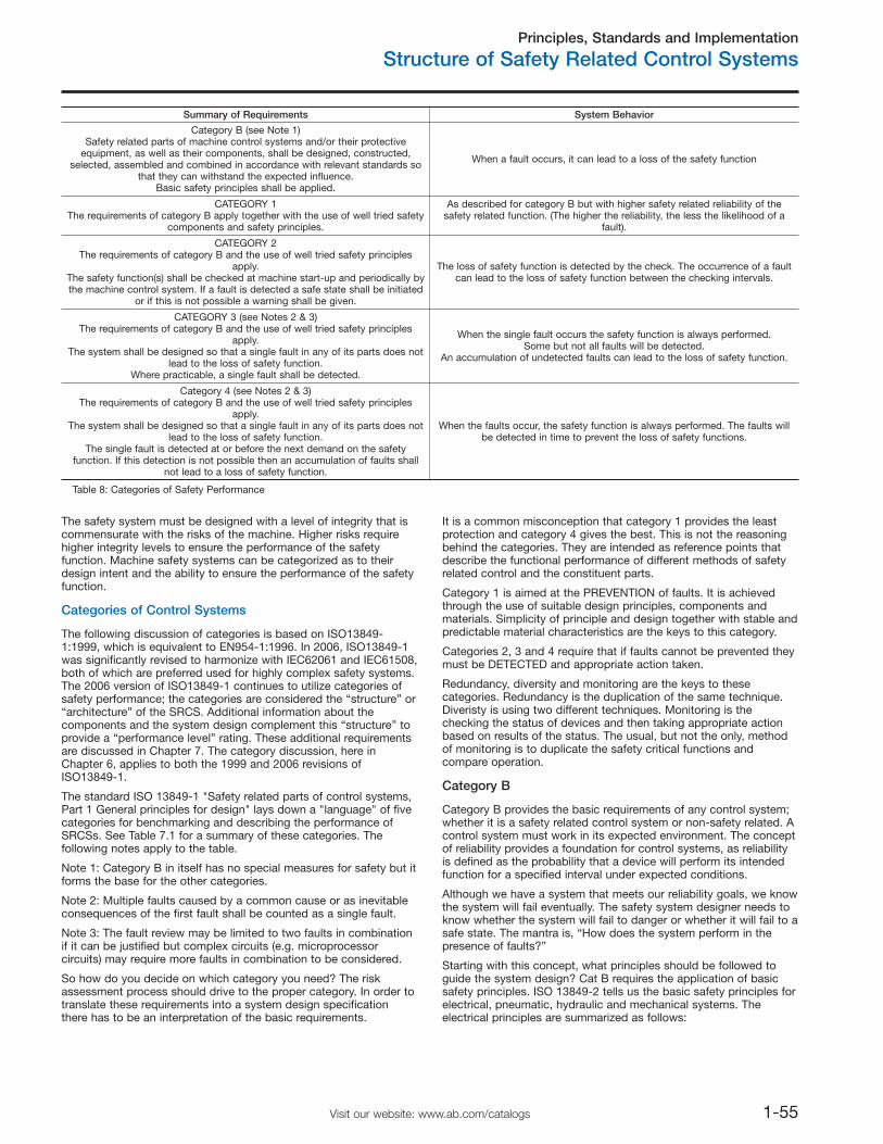
Principles, Standards and Implementation
Structure of Safety Related Control Systems
1-55Visit our website: www.ab.com/catalogs
The safety system must be designed with a level of integrity that iscommensurate with the risks of the machine. Higher risks requirehigher integrity levels to ensure the performance of the safetyfunction. Machine safety systems can be categorized as to theirdesign intent and the ability to ensure the performance of the safetyfunction.
Categories of Control Systems
Summary of Requirements System Behavior
Category B (see Note 1)Safety related parts of machine control systems and/or their protective
equipment, as well as their components, shall be designed, constructed,selected, assembled and combined in accordance with relevant standards so
that they can withstand the expected influence.Basic safety principles shall be applied.
When a fault occurs, it can lead to a loss of the safety function
CATEGORY 1The requirements of category B apply together with the use of well tried safety
components and safety principles.
As described for category B but with higher safety related reliability of thesafety related function. (The higher the reliability, the less the likelihood of a
fault).
CATEGORY 2The requirements of category B and the use of well tried safety principles
apply.The safety function(s) shall be checked at machine start-up and periodically bythe machine control system. If a fault is detected a safe state shall be initiated
or if this is not possible a warning shall be given.
The loss of safety function is detected by the check. The occurrence of a faultcan lead to the loss of safety function between the checking intervals.
CATEGORY 3 (see Notes 2 & 3)The requirements of category B and the use of well tried safety principles
apply.The system shall be designed so that a single fault in any of its parts does not
lead to the loss of safety function.Where practicable, a single fault shall be detected.
When the single fault occurs the safety function is always performed.Some but not all faults will be detected.
An accumulation of undetected faults can lead to the loss of safety function.
Category 4 (see Notes 2 & 3)The requirements of category B and the use of well tried safety principles
apply.The system shall be designed so that a single fault in any of its parts does not
lead to the loss of safety function.The single fault is detected at or before the next demand on the safety
function. If this detection is not possible then an accumulation of faults shallnot lead to a loss of safety function.
When the faults occur, the safety function is always performed. The faults willbe detected in time to prevent the loss of safety functions.
Table 8: Categories of Safety Performance
The following discussion of categories is based on ISO13849-1:1999, which is equivalent to EN954-1:1996. In 2006, ISO13849-1was significantly revised to harmonize with IEC62061 and IEC61508,both of which are preferred used for highly complex safety systems.The 2006 version of ISO13849-1 continues to utilize categories ofsafety performance; the categories are considered the “structure” or“architecture” of the SRCS. Additional information about thecomponents and the system design complement this “structure” toprovide a “performance level” rating. These additional requirementsare discussed in Chapter 7. The category discussion, here inChapter 6, applies to both the 1999 and 2006 revisions ofISO13849-1.
The standard ISO 13849-1 "Safety related parts of control systems,Part 1 General principles for design" lays down a "language" of fivecategories for benchmarking and describing the performance ofSRCSs. See Table 7.1 for a summary of these categories. Thefollowing notes apply to the table.
Note 1: Category B in itself has no special measures for safety but itforms the base for the other categories.
Note 2: Multiple faults caused by a common cause or as inevitableconsequences of the first fault shall be counted as a single fault.
Note 3: The fault review may be limited to two faults in combinationif it can be justified but complex circuits (e.g. microprocessorcircuits) may require more faults in combination to be considered.
So how do you decide on which category you need? The riskassessment process should drive to the proper category. In order totranslate these requirements into a system design specificationthere has to be an interpretation of the basic requirements.
It is a common misconception that category 1 provides the leastprotection and category 4 gives the best. This is not the reasoningbehind the categories. They are intended as reference points thatdescribe the functional performance of different methods of safetyrelated control and the constituent parts.
Category 1 is aimed at the PREVENTION of faults. It is achievedthrough the use of suitable design principles, components andmaterials. Simplicity of principle and design together with stable andpredictable material characteristics are the keys to this category.
Categories 2, 3 and 4 require that if faults cannot be prevented theymust be DETECTED and appropriate action taken.
Redundancy, diversity and monitoring are the keys to thesecategories. Redundancy is the duplication of the same technique.Diveristy is using two different techniques. Monitoring is thechecking the status of devices and then taking appropriate actionbased on results of the status. The usual, but not the only, methodof monitoring is to duplicate the safety critical functions andcompare operation.
Category B
Category B provides the basic requirements of any control system;whether it is a safety related control system or non-safety related. Acontrol system must work in its expected environment. The conceptof reliability provides a foundation for control systems, as reliabilityis defined as the probability that a device will perform its intendedfunction for a specified interval under expected conditions.
Although we have a system that meets our reliability goals, we knowthe system will fail eventually. The safety system designer needs toknow whether the system will fail to danger or whether it will fail to asafe state. The mantra is, “How does the system perform in thepresence of faults?”
Starting with this concept, what principles should be followed toguide the system design? Cat B requires the application of basicsafety principles. ISO 13849-2 tells us the basic safety principles forelectrical, pneumatic, hydraulic and mechanical systems. Theelectrical principles are summarized as follows:
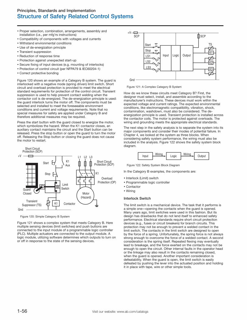
Principles, Standards and Implementation
Structure of Safety Related Control Systems
1-56 Visit our website: www.ab.com/catalogs
Proper selection, combination, arrangements, assembly andinstallation (i.e., per mfg’rs instructions)Compatibility of components with voltages and currentsWithstand environmental conditionsUse of de-energization principleTransient suppressionReduction of response timeProtection against unexpected start-upSecure fixing of input devices (e.g. mounting of interlocks)Protection of control circuit (per NFPA79 & IEC60204-1)Correct protective bonding
Figure 120 shows an example of a Category B system. The guard isinterlocked with a negative mode (spring driven) limit switch. Shortcircuit and overload protection is provided to meet the electricalstandard requirements for protection of the control circuit. Transientsuppression is used to help prevent contact welding when thecontactor coil is de-energized. The de-energization principle is used:the guard interlock turns the motor off. The components must beselected and installed to meet the foreseeable environmentconditions and current and voltage requirements. Note that nospecial measures for safety are applied under Category B andtherefore additional measures may be required.
Press the start button with the guard closed to energize the motor,which symbolizes the hazard. When the K1 contactor closes, anauxiliary contact maintains the circuit and the Start button can bereleased. Press the stop button or open the guard to turn the motoroff. Releasing the Stop button or closing the guard does not causethe motor to restart.
Start
K1
GuardClosed
ContactorTransient
Suppressor (TS)
LimitSwitch
K1Aux
Motor(Hazard)
K1
Short CircuitProtection (SCP)
Short CircuitProtection (SCP)
L1 L2 L3
Stop Overload
Protection (OP)
+V
Gnd
Figure 120: Simple Category B System
Figure 121 shows a complex system that meets Category B. Heremultiple sensing devices (limit switches) and push buttons areconnected to the input module of a programmable logic controller(PLC). Multiple actuators are connected to the output module. Alogic module, utilizing software determines which outputs to turn onor off in response to the state of the sensing devices.
OutputLogicInput
Start
Stop
LS1
LS2
LS3
K1
K2
K3
+V
Gnd
SCP SCP
TS
Figure 121: A Complex Category B System
How do we know these circuits meet Category B? First, thedesigner must select, install, and assemble according to themanufacturer’s instructions. These devices must work within theexpected voltage and current ratings. The expected environmentalconditions, like electromagnetic compatibility, vibration, shock,contamination, washdown, must also be considered. The de-energization principle is used. Transient protection is installed acrossthe contactor coils. The motor is protected against overloads. Thewiring and grounding meets the appropriate electrical standards.
The next step in the safety analysis is to separate the system into itsmajor components and consider their modes of potential failure. InChapter 4, we looked at the system as three blocks. Whenconsidering safety system performance, the wiring must also beincluded in the analysis. Figure 122 shows the safety system blockdiagram.
Input Logic OutputWiringWiring
Figure 122: Safety System Block Diagram
In the Category B examples, the components are:
Interlock (Limit) switchProgrammable logic controllerContactorWiring
Interlock Switch
The limit switch is a mechanical device. The task that it performs isa simple one—opening the contacts when the guard is opened.Many years ago, limit switches were used in this fashion. But itsdesign has drawbacks that do not lend itself to enhanced safetyperformance. Electrical standards require short circuit protectiondevices (e.g., fuses or circuit breakers) for branch circuits. Thisprotection may not be enough to prevent a welded contact in thelimit switch. The contacts in the limit switch are designed to openby the force of a spring. Unfortunately, the spring force is not alwaysstrong enough to overcome the force of a welded contact. A secondconsideration is the spring itself. Repeated flexing may eventuallylead to breakage, and the force exerted on the contacts may not beenough to open the circuit. Other internal faults in the operator heador the linkage may also result in the contacts remaining closed,when the guard is opened. Another important consideration isdefeatability. When the guard is open, the limit switch is easilydefeated by pushing the lever into the actuated position and holdingit in place with tape, wire or other simple tools.
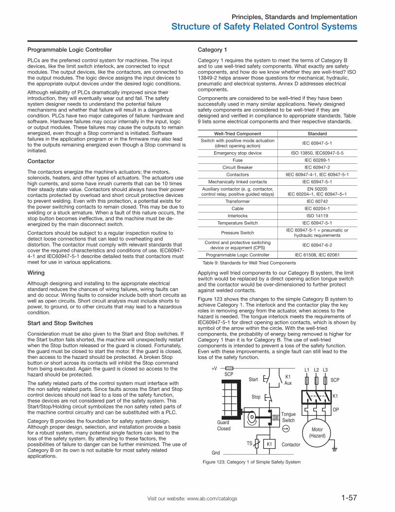
Principles, Standards and Implementation
Structure of Safety Related Control Systems
1-57Visit our website: www.ab.com/catalogs
Programmable Logic Controller
PLCs are the preferred control system for machines. The inputdevices, like the limit switch interlock, are connected to inputmodules. The output devices, like the contactors, are connected tothe output modules. The logic device assigns the input devices tothe appropriate output devices under the desired logic conditions.
Although reliability of PLCs dramatically improved since theirintroduction, they will eventually wear out and fail. The safetysystem designer needs to understand the potential failuremechanisms and whether that failure will result in a dangerouscondition. PLCs have two major categories of failure: hardware andsoftware. Hardware failures may occur internally in the input, logicor output modules. These failures may cause the outputs to remainenergized, even though a Stop command is initiated. Softwarefailures in the application program or in the firmware may also leadto the outputs remaining energized even though a Stop command isinitiated.
Contactor
The contactors energize the machine’s actuators; the motors,solenoids, heaters, and other types of actuators. The actuators usehigh currents, and some have inrush currents that can be 10 timestheir steady state value. Contactors should always have their powercontacts protected by overload and short circuit protective devicesto prevent welding. Even with this protection, a potential exists forthe power switching contacts to remain closed. This may be due towelding or a stuck armature. When a fault of this nature occurs, thestop button becomes ineffective, and the machine must be de-energized by the main disconnect switch.
Contactors should be subject to a regular inspection routine todetect loose connections that can lead to overheating anddistortion. The contactor must comply with relevant standards thatcover the required characteristics and conditions of use. IEC60947-4-1 and IEC60947-5-1 describe detailed tests that contactors mustmeet for use in various applications.
Wiring
Although designing and installing to the appropriate electricalstandard reduces the chances of wiring failures, wiring faults canand do occur. Wiring faults to consider include both short circuits aswell as open circuits. Short circuit analysis must include shorts topower, to ground, or to other circuits that may lead to a hazardouscondition.
Start and Stop Switches
Consideration must be also given to the Start and Stop switches. Ifthe Start button fails shorted, the machine will unexpectedly restartwhen the Stop button released or the guard is closed. Fortunately,the guard must be closed to start the motor. If the guard is closed,then access to the hazard should be protected. A broken Stopbutton or short across its contacts will inhibit the Stop commandfrom being executed. Again the guard is closed so access to thehazard should be protected.
The safety related parts of the control system must interface withthe non safety related parts. Since faults across the Start and Stopcontrol devices should not lead to a loss of the safety function,these devices are not considered part of the safety system. ThisStart/Stop/Holding circuit symbolizes the non safety rated parts ofthe machine control circuitry and can be substituted with a PLC.
Category B provides the foundation for safety system design.Although proper design, selection, and installation provide a basisfor a robust system, many potential single factors can lead to theloss of the safety system. By attending to these factors, thepossibilities of failure to danger can be further minimized. The use ofCategory B on its own is not suitable for most safety relatedapplications.
Category 1
Category 1 requires the system to meet the terms of Category Band to use well-tried safety components. What exactly are safetycomponents, and how do we know whether they are well-tried? ISO13849-2 helps answer those questions for mechanical, hydraulic,pneumatic and electrical systems. Annex D addresses electricalcomponents.
Components are considered to be well–tried if they have beensuccessfully used in many similar applications. Newly designedsafety components are considered to be well-tried if they aredesigned and verified in compliance to appropriate standards. Table9 lists some electrical components and their respective standards.
Well-Tried Component Standard
Switch with positive mode actuation(direct opening action) IEC 60947-5-1
Emergency stop device ISO 13850, IEC60947-5-5
Fuse IEC 60269-1
Circuit Breaker IEC 60947-2
Contactors IIEC 60947-4-1, IEC 60947-5-1
Mechanically linked contacts IEC 60947-5-1
Auxiliary contactor (e. g. contactor,control relay, positive guided relays)
EN 50205IEC 60204–1, IEC 60947–5–1
Transformer IEC 60742
Cable IEC 60204-1
Interlocks ISO 14119
Temperature Switch IEC 60947-5-1
Pressure Switch IEC 60947-5-1 + pneumatic orhydraulic requirements
Control and protective switchingdevice or equipment (CPS) IEC 60947-6-2
Programmable Logic Controller IEC 61508, IEC 62061
Table 9: Standards for Well Tried Components
Applying well tried components to our Category B system, the limitswitch would be replaced by a direct opening action tongue switchand the contactor would be over-dimensioned to further protectagainst welded contacts.
Figure 123 shows the changes to the simple Category B system toachieve Category 1. The interlock and the contactor play the keyroles in removing energy from the actuator, when access to thehazard is needed. The tongue interlock meets the requirements ofIEC60947-5-1 for direct opening action contacts, which is shown bysymbol of the arrow within the circle. With the well-triedcomponents, the probability of energy being removed is higher forCategory 1 than it is for Category B. The use of well-triedcomponents is intended to prevent a loss of the safety function.Even with these improvements, a single fault can still lead to theloss of the safety function.
Start
K1
GuardClosed
ContactorTS
TongueSwitch
K1Aux
Motor(Hazard)
K1
L1 L2 L3
Stop
OP
+VSCP
SCP
Gnd
Figure 123: Category 1 of Simple Safety System
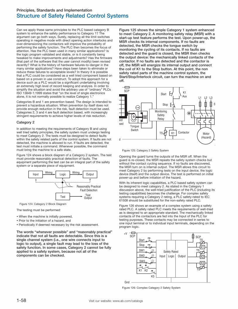
Principles, Standards and Implementation
Structure of Safety Related Control Systems
1-58 Visit our website: www.ab.com/catalogs
Can we apply these same principles to the PLC based category Bsystem to enhance the safety performance to Category 1? Theargument can go both ways. Surely, replacing all the limit switchesoperating in negative mode with direct opening action interlocks andover-dimensioning the contactors will improve the probability ofperforming the safety function. The PLC then becomes the focus ofattention. Has the PLC been used in many similar applications? Isthe logic program validated and stable, or is it constantly beingtweaked to make improvements and adjustments? Has the firmware(that part of the software that the user cannot modify) been revisedrecently? What is the history of hardware failures-to-danger in themany similar applications? Have steps been taken to eliminate orreduce these failures to acceptable levels? In theory it is possiblethat a PLC could be considered as a well tried component based onbased on a proven in use construct. To adopt this approach for adevice such as a PLC would be a significant undertaking involvingan extremely high level of record keeping and analysis. In order tosimplify the situation and avoid the arbitrary use of “ordinary” PLCsISO 13849-1:1999 states that “on the level of single electronicsalone, it is not normally possible to realize Category 1.”
Categories B and 1 are prevention based. The design is intended toprevent a hazardous situation. When prevention by itself does notprovide enough reduction in the risk, fault detection must be used.Categories 2, 3 and 4 are fault detection based, with increasinglystringent requirements to achieve higher levels of risk reduction.
Category 2
In addition to meeting the requirements of Category B and usingwell tried safety principles, the safety system must undergo testingto meet Category 2. The tests must be designed to detect faultswithin the safety related parts of the control system. If faults are notdetected, the machine is allowed to run. If faults are detected, thetest must initiate a command. Whenever possible, the commandmust bring the machine to a safe state.
Figure 124 shows a block diagram of a Category 2 system. The testmust provide reasonably practical detection of faults. Theequipment performing the test can be an integral part of the safetysystem or a separate piece of equipment.
Input Logic
Test
OutputWiringWiring
TestOutput
Reasonably PracticalFault Detection
Figure 124: Category 2 Block Diagram
The testing must be performed:
When the machine is initially powered,Prior to the initiation of a hazard, andPeriodically if deemed necessary by the risk assessment.
The words “whenever possible” and “reasonably practical”indicate that not all faults are detectable. Since this is asingle channel system (i.e., one wire connects input tologic to output), a single fault may lead to the loss of thesafety function. In some cases, Category 2 cannot be fullyapplied to a safety system, because not all of thecomponents can be checked.
Figure 125 shows the simple Category 1 system enhancedto meet Category 2. A monitoring safety relay (MSR) with astart-up test feature performs the test. Upon power-up, theMSR checks its internal components. If no faults aredetected, the MSR checks the tongue switch bymonitoring the cycling of its contacts. If no faults aredetected and the guard is closed, the MSR then checksthe output device: the mechanically linked contacts of thecontactor. If no faults are detected and the contactor isoff, the MSR will energize its internal output and connectthe coil of K1 to the Stop button. At this point, the nonsafety rated parts of the machine control system, theStart/Stop/Interlock circuit, can turn the machine on andoff.
Start
K1
ardsed
TongueSwitch
K1Aux
Motor(Hazard)
SCP
S
TS
L1 L2 L3
Stop
d
MonitoringSafetyRelay
Contactor
Figure 125: Category 2 Safety System
Opening the guard turns the outputs of the MSR off. When theguard is re-closed, the MSR repeats the safety system checks butwithout the contact cycling sequence. If no faults are discovered,the MSR turn on is internal output. The MSR allows this circuit tomeet Category 2 by performing tests on the input device, the logicdevice (itself) and the output device. The test is performed on initialpower-up and before initiation of the hazard.
With its inherent logic capabilities, a PLC based safety system canbe designed to meet category 2. As stated in the Category 1discussion above, the well-tried justification of the PLC (including itstesting capabilities) becomes the challenge. For complex safetysystems requiring a Category 2 rating, a PLC safety-rated to IEC61508 should be substituted for the non-safety rated PLC.
Figure 126 shows an example of a complex system using a safetyrated PLC. A safety rated PLC meets the requirements of well-triedas is designed to an appropriate standard. The mechanically linkedcontacts of the contactors are fed into the Input of the PLC fortesting purposes. These contacts may be connected in series toone input terminal or to individual input terminals, depending on theprogram logic.
OutputLogicInput
Start
+V
Gnd
SCP SCP
Stop
SW1
SW2
SW3
K3
K2K1
K1
K2
K3
Safety Rated
TS
TS
TS
Figure 126: Complex Category 2 Safety System
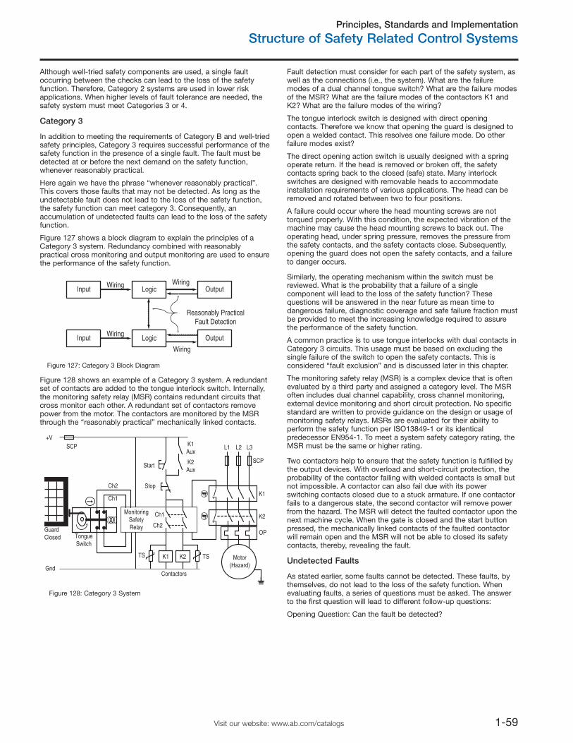
Principles, Standards and Implementation
Structure of Safety Related Control Systems
1-59Visit our website: www.ab.com/catalogs
Although well-tried safety components are used, a single faultoccurring between the checks can lead to the loss of the safetyfunction. Therefore, Category 2 systems are used in lower riskapplications. When higher levels of fault tolerance are needed, thesafety system must meet Categories 3 or 4.
Category 3
In addition to meeting the requirements of Category B and well-triedsafety principles, Category 3 requires successful performance of thesafety function in the presence of a single fault. The fault must bedetected at or before the next demand on the safety function,whenever reasonably practical.
Here again we have the phrase “whenever reasonably practical”.This covers those faults that may not be detected. As long as theundetectable fault does not lead to the loss of the safety function,the safety function can meet category 3. Consequently, anaccumulation of undetected faults can lead to the loss of the safetyfunction.
Figure 127 shows a block diagram to explain the principles of aCategory 3 system. Redundancy combined with reasonablypractical cross monitoring and output monitoring are used to ensurethe performance of the safety function.
Input Logic Output
Wiring
Wiring
Input Logic OutputWiringWiring
Reasonably PracticalFault Detection
Figure 127: Category 3 Block Diagram
Figure 128 shows an example of a Category 3 system. A redundantset of contacts are added to the tongue interlock switch. Internally,the monitoring safety relay (MSR) contains redundant circuits thatcross monitor each other. A redundant set of contactors removepower from the motor. The contactors are monitored by the MSRthrough the “reasonably practical” mechanically linked contacts.
Fault detection must consider for each part of the safety system, aswell as the connections (i.e., the system). What are the failuremodes of a dual channel tongue switch? What are the failure modesof the MSR? What are the failure modes of the contactors K1 andK2? What are the failure modes of the wiring?
The tongue interlock switch is designed with direct openingcontacts. Therefore we know that opening the guard is designed toopen a welded contact. This resolves one failure mode. Do otherfailure modes exist?
The direct opening action switch is usually designed with a springoperate return. If the head is removed or broken off, the safetycontacts spring back to the closed (safe) state. Many interlockswitches are designed with removable heads to accommodateinstallation requirements of various applications. The head can beremoved and rotated between two to four positions.
A failure could occur where the head mounting screws are nottorqued properly. With this condition, the expected vibration of themachine may cause the head mounting screws to back out. Theoperating head, under spring pressure, removes the pressure fromthe safety contacts, and the safety contacts close. Subsequently,opening the guard does not open the safety contacts, and a failureto danger occurs.
Similarly, the operating mechanism within the switch must bereviewed. What is the probability that a failure of a singlecomponent will lead to the loss of the safety function? Thesequestions will be answered in the near future as mean time todangerous failure, diagnostic coverage and safe failure fraction mustbe provided to meet the increasing knowledge required to assurethe performance of the safety function.
A common practice is to use tongue interlocks with dual contacts inCategory 3 circuits. This usage must be based on excluding thesingle failure of the switch to open the safety contacts. This isconsidered “fault exclusion” and is discussed later in this chapter.
The monitoring safety relay (MSR) is a complex device that is oftenevaluated by a third party and assigned a category level. The MSRoften includes dual channel capability, cross channel monitoring,external device monitoring and short circuit protection. No specificstandard are written to provide guidance on the design or usage ofmonitoring safety relays. MSRs are evaluated for their ability toperform the safety function per ISO13849-1 or its identicalpredecessor EN954-1. To meet a system safety category rating, theMSR must be the same or higher rating.
Two contactors help to ensure that the safety function is fulfilled bythe output devices. With overload and short-circuit protection, theprobability of the contactor failing with welded contacts is small butnot impossible. A contactor can also fail due with its powerswitching contacts closed due to a stuck armature. If one contactorfails to a dangerous state, the second contactor will remove powerfrom the hazard. The MSR will detect the faulted contactor upon thenext machine cycle. When the gate is closed and the start buttonpressed, the mechanically linked contacts of the faulted contactorwill remain open and the MSR will not be able to closed its safetycontacts, thereby, revealing the fault.
Start
K1
GuardClosed Tongue
Switch
K2Aux
K1Aux
Motor(Hazard)
K2
K1
L1 L2 L3
Stop
K2
+V
ContactorsGnd
MonitoringSafetyRelay
SCP
SCP
OP
Ch1
Ch1
Ch2
Ch2
TS TS
Figure 128: Category 3 System
Undetected Faults
As stated earlier, some faults cannot be detected. These faults, bythemselves, do not lead to the loss of the safety function. Whenevaluating faults, a series of questions must be asked. The answerto the first question will lead to different follow-up questions:
Opening Question: Can the fault be detected?
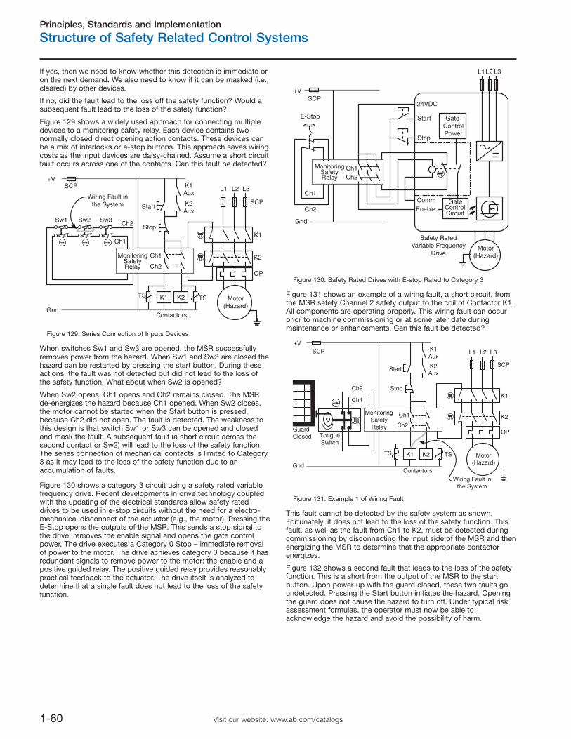
Principles, Standards and Implementation
Structure of Safety Related Control Systems
1-60 Visit our website: www.ab.com/catalogs
If yes, then we need to know whether this detection is immediate oron the next demand. We also need to know if it can be masked (i.e.,cleared) by other devices.
If no, did the fault lead to the loss off the safety function? Would asubsequent fault lead to the loss of the safety function?
Figure 129 shows a widely used approach for connecting multipledevices to a monitoring safety relay. Each device contains twonormally closed direct opening action contacts. These devices canbe a mix of interlocks or e-stop buttons. This approach saves wiringcosts as the input devices are daisy-chained. Assume a short circuitfault occurs across one of the contacts. Can this fault be detected?
Start
K1
K2Aux
K1Aux
Motor(Hazard)
K2
K1
SCP L1 L2 L3
Stop
K2
+V
Gnd
MonitoringSafetyRelay
Contactors
SCP
OP
Ch1
Ch1
Ch2
Ch2Sw1 Sw2 Sw3
Wiring Fault inthe System
TS TS
Figure 129: Series Connection of Inputs Devices
When switches Sw1 and Sw3 are opened, the MSR successfullyremoves power from the hazard. When Sw1 and Sw3 are closed thehazard can be restarted by pressing the start button. During theseactions, the fault was not detected but did not lead to the loss ofthe safety function. What about when Sw2 is opened?
When Sw2 opens, Ch1 opens and Ch2 remains closed. The MSRde-energizes the hazard because Ch1 opened. When Sw2 closes,the motor cannot be started when the Start button is pressed,because Ch2 did not open. The fault is detected. The weakness tothis design is that switch Sw1 or Sw3 can be opened and closedand mask the fault. A subsequent fault (a short circuit across thesecond contact or Sw2) will lead to the loss of the safety function.The series connection of mechanical contacts is limited to Category3 as it may lead to the loss of the safety function due to anaccumulation of faults.
Figure 130 shows a category 3 circuit using a safety rated variablefrequency drive. Recent developments in drive technology coupledwith the updating of the electrical standards allow safety rateddrives to be used in e-stop circuits without the need for a electro-mechanical disconnect of the actuator (e.g., the motor). Pressing theE-Stop opens the outputs of the MSR. This sends a stop signal tothe drive, removes the enable signal and opens the gate controlpower. The drive executes a Category 0 Stop – immediate removalof power to the motor. The drive achieves category 3 because it hasredundant signals to remove power to the motor: the enable and apositive guided relay. The positive guided relay provides reasonablypractical feedback to the actuator. The drive itself is analyzed todetermine that a single fault does not lead to the loss of the safetyfunction.
+V
Gnd
MonitoringSafetyRelay
Ch1
Ch1Ch2
Ch2
SCP
E-Stop
Stop
Start
Motor(Hazard)
L1L2 L3
Enable
24VDC
Safety RatedVariable Frequency
Drive
Comm GateControlCircuit
Gate ControlPower
Figure 130: Safety Rated Drives with E-stop Rated to Category 3
Figure 131 shows an example of a wiring fault, a short circuit, fromthe MSR safety Channel 2 safety output to the coil of Contactor K1.All components are operating properly. This wiring fault can occurprior to machine commissioning or at some later date duringmaintenance or enhancements. Can this fault be detected?
Start
K1
GuardClosed Tongue
Switch
K2Aux
K1Aux
Motor(Hazard)
K2
K1
L1 L2 L3
Stop
K2
+V
ContactorsGnd
MonitoringSafetyRelay
Wiring Fault inthe System
SCP
SCP
OP
Ch1
Ch1
Ch2
Ch2
TS TS
Figure 131: Example 1 of Wiring Fault
This fault cannot be detected by the safety system as shown.Fortunately, it does not lead to the loss of the safety function. Thisfault, as well as the fault from Ch1 to K2, must be detected duringcommissioning by disconnecting the input side of the MSR and thenenergizing the MSR to determine that the appropriate contactorenergizes.
Figure 132 shows a second fault that leads to the loss of the safetyfunction. This is a short from the output of the MSR to the startbutton. Upon power-up with the guard closed, these two faults goundetected. Pressing the Start button initiates the hazard. Openingthe guard does not cause the hazard to turn off. Under typical riskassessment formulas, the operator must now be able toacknowledge the hazard and avoid the possibility of harm.
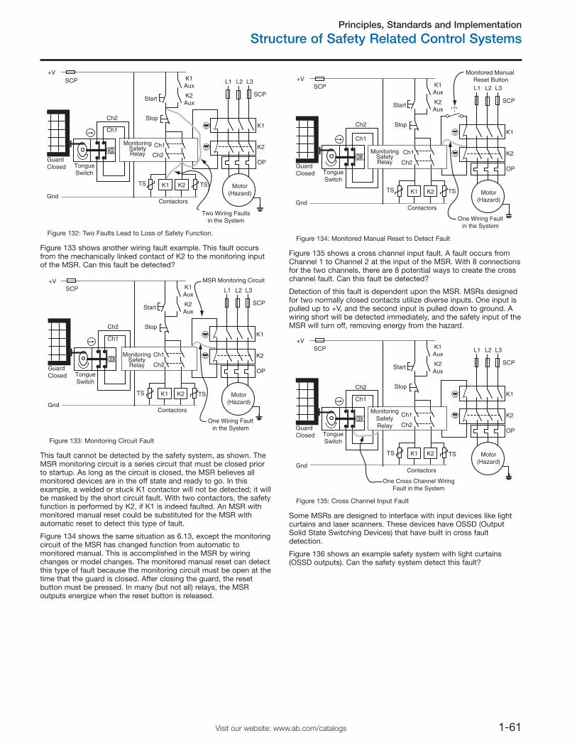
Principles, Standards and Implementation
Structure of Safety Related Control Systems
1-61Visit our website: www.ab.com/catalogs
Start
K1
GuardClosed Tongue
Switch
K2Aux
K1Aux
Motor(Hazard)
K2
K1
L1 L2 L3
Stop
K2
+V
ContactorsGnd
MonitoringSafetyRelay
Two Wiring Faultsin the System
SCP
SCP
OP
Ch1
Ch1
Ch2
Ch2
TS TS
Figure 132: Two Faults Lead to Loss of Safety Function.
Figure 133 shows another wiring fault example. This fault occursfrom the mechanically linked contact of K2 to the monitoring inputof the MSR. Can this fault be detected?
Start
K1
GuardClosed Tongue
Switch
K2Aux
K1Aux
Motor(Hazard)
K2
K1
SCP L1 L2 L3
Stop
K2
+V
ContactorsGnd
MonitoringSafetyRelay
One Wiring Faultin the System
MSR Monitoring Circuit
SCP
OP
Ch1
Ch1
Ch2
Ch2
TS TS
Figure 133: Monitoring Circuit Fault
This fault cannot be detected by the safety system, as shown. TheMSR monitoring circuit is a series circuit that must be closed priorto startup. As long as the circuit is closed, the MSR believes allmonitored devices are in the off state and ready to go. In thisexample, a welded or stuck K1 contactor will not be detected; it willbe masked by the short circuit fault. With two contactors, the safetyfunction is performed by K2, if K1 is indeed faulted. An MSR withmonitored manual reset could be substituted for the MSR withautomatic reset to detect this type of fault.
Figure 134 shows the same situation as 6.13, except the monitoringcircuit of the MSR has changed function from automatic tomonitored manual. This is accomplished in the MSR by wiringchanges or model changes. The monitored manual reset can detectthis type of fault because the monitoring circuit must be open at thetime that the guard is closed. After closing the guard, the resetbutton must be pressed. In many (but not all) relays, the MSRoutputs energize when the reset button is released.
Start
K1
GuardClosed Tongue
Switch
K2Aux
K1Aux
Motor(Hazard)
K2
K1
SCP L1 L2 L3
Stop
K2
+V
ContactorsGnd
MonitoringSafetyRelay
One Wiring Faultin the System
Monitored Manual Reset Button
SCP
OP
Ch1
Ch1
Ch2
Ch2
TS TS
Figure 134: Monitored Manual Reset to Detect Fault
Figure 135 shows a cross channel input fault. A fault occurs fromChannel 1 to Channel 2 at the input of the MSR. With 8 connectionsfor the two channels, there are 8 potential ways to create the crosschannel fault. Can this fault be detected?
Detection of this fault is dependent upon the MSR. MSRs designedfor two normally closed contacts utilize diverse inputs. One input ispulled up to +V, and the second input is pulled down to ground. Awiring short will be detected immediately, and the safety input of theMSR will turn off, removing energy from the hazard.
Start
K1
GuardClosed Tongue
Switch
K2Aux
K1Aux
Motor(Hazard)
K2
K1
L1 L2 L3
Stop
K2
+V
Gnd
MonitoringSafetyRelay
Contactors
SCP
OP
One Cross Channel WiringFault in the System
Ch1
Ch1
Ch2
Ch2
SCP
TS TS
Figure 135: Cross Channel Input Fault
Some MSRs are designed to interface with input devices like lightcurtains and laser scanners. These devices have OSSD (OutputSolid State Switching Devices) that have built in cross faultdetection.
Figure 136 shows an example safety system with light curtains(OSSD outputs). Can the safety system detect this fault?
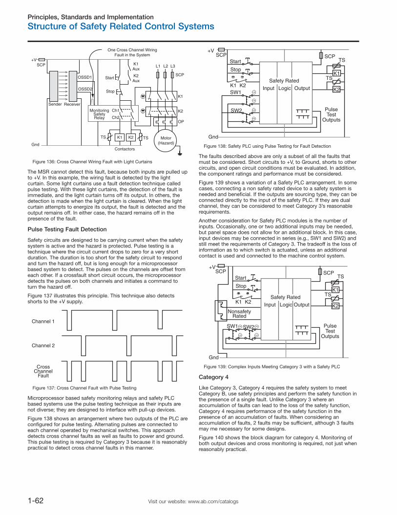
Principles, Standards and Implementation
Structure of Safety Related Control Systems
1-62 Visit our website: www.ab.com/catalogs
Start
K1
K2Aux
K1Aux
Motor(Hazard)
K2
K1
L1 L2 L3
Stop
K2
+V
Gnd
MonitoringSafetyRelay
Contactors
SCP
OP
Ch1
Ch2
One Cross Channel WiringFault in the System
Sender Receiver
OSSD2
OSSD1
SCP
TS TS
Figure 136: Cross Channel Wiring Fault with Light Curtains
The MSR cannot detect this fault, because both inputs are pulled upto +V. In this example, the wiring fault is detected by the lightcurtain. Some light curtains use a fault detection technique calledpulse testing. With these light curtains, the detection of the fault isimmediate, and the light curtain turns off its output. In others, thedetection is made when the light curtain is cleared. When the lightcurtain attempts to energize its output, the fault is detected and theoutput remains off. In either case, the hazard remains off in thepresence of the fault.
Pulse Testing Fault Detection
Safety circuits are designed to be carrying current when the safetysystem is active and the hazard is protected. Pulse testing is atechnique where the circuit current drops to zero for a very shortduration. The duration is too short for the safety circuit to respondand turn the hazard off, but is long enough for a microprocessorbased system to detect. The pulses on the channels are offset fromeach other. If a crossfault short circuit occurs, the microprocessordetects the pulses on both channels and initiates a command toturn the hazard off.
Figure 137 illustrates this principle. This technique also detectsshorts to the +V supply.
Channel 1
Channel 2
CrossChannel
Fault
Figure 137: Cross Channel Fault with Pulse Testing
Microprocessor based safety monitoring relays and safety PLCbased systems use the pulse testing technique as their inputs arenot diverse; they are designed to interface with pull-up devices.
Figure 138 shows an arrangement where two outputs of the PLC areconfigured for pulse testing. Alternating pulses are connected toeach channel operated by mechanical switches. This approachdetects cross channel faults as well as faults to power and ground.This pulse testing is required by Category 3 because it is reasonablypractical to detect cross channel faults in this manner.
OutputLogicInput
Start
+V
Gnd
SCP SCP
Stop
SW1
SW2
K2K1
K1
K2
Safety Rated
PulseTest
Outputs
TS
TS
Figure 138: Safety PLC using Pulse Testing for Fault Detection
The faults described above are only a subset of all the faults thatmust be considered. Short circuits to +V, to Ground, shorts to othercircuits, and open circuit conditions must be evaluated. In addition,the component ratings and performance must be considered.
Figure 139 shows a variation of a Safety PLC arrangement. In somecases, connecting a non safety rated device to a safety system isneeded and beneficial. If the outputs are sourcing type, they can beconnected directly to the input of the safety PLC. If they are dualchannel, they can be considered to meet Category 3’s reasonablerequirements.
Another consideration for Safety PLC modules is the number ofinputs. Occasionally, one or two additional inputs may be needed,but panel space does not allow for an additional block. In this case,input devices may be connected in series (e.g., SW1 and SW2) andstill meet the requirements of Category 3. The tradeoff is the loss ofinformation as to which switch is actuated, unless an additionalcontact is used and connected to the machine control system.
OutputLogicInput
Start
+V
Gnd
SCP SCP
Stop
SW1
K2K1
K1
K2
Safety Rated
SW2 PulseTest
Outputs
TS
TS
NonsafetyRated
Figure 139: Complex Inputs Meeting Category 3 with a Safety PLC
Category 4
Like Category 3, Category 4 requires the safety system to meetCategory B, use safety principles and perform the safety function inthe presence of a single fault. Unlike Category 3 where anaccumulation of faults can lead to the loss of the safety function,Category 4 requires performance of the safety function in thepresence of an accumulation of faults. When considering anaccumulation of faults, 2 faults may be sufficient, although 3 faultsmay me necessary for some designs.
Figure 140 shows the block diagram for category 4. Monitoring ofboth output devices and cross monitoring is required, not just whenreasonably practical.
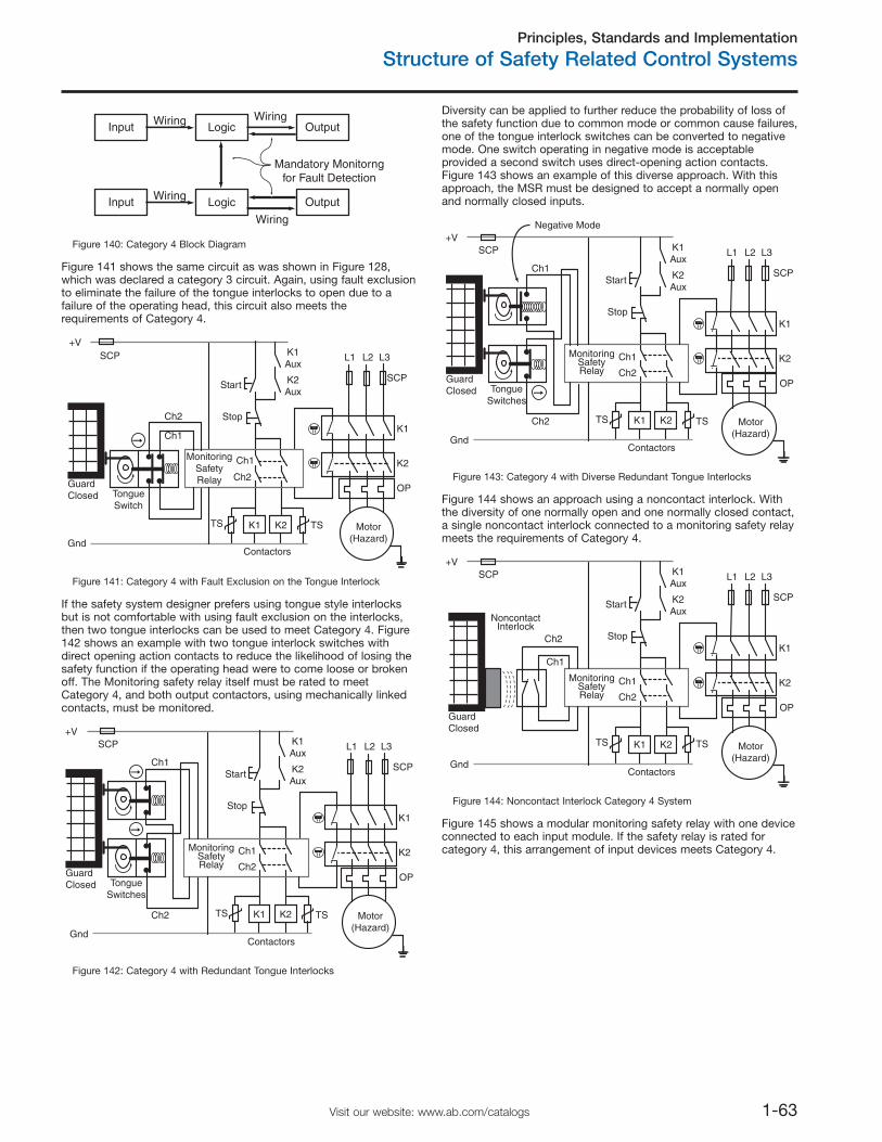
Principles, Standards and Implementation
Structure of Safety Related Control Systems
1-63Visit our website: www.ab.com/catalogs
Input Logic Output
Wiring
Wiring
Input Logic OutputWiringWiring
Mandatory Monitorngfor Fault Detection
Figure 140: Category 4 Block Diagram
Figure 141 shows the same circuit as was shown in Figure 128,which was declared a category 3 circuit. Again, using fault exclusionto eliminate the failure of the tongue interlocks to open due to afailure of the operating head, this circuit also meets therequirements of Category 4.
Start
K1
GuardClosed Tongue
Switch
K2Aux
K1Aux
Motor(Hazard)
K2
K1
L1 L2 L3
Stop
K2
+V
ContactorsGnd
MonitoringSafetyRelay
SCP
SCP
OP
Ch1
Ch1
Ch2
Ch2
TS TS
Figure 141: Category 4 with Fault Exclusion on the Tongue Interlock
If the safety system designer prefers using tongue style interlocksbut is not comfortable with using fault exclusion on the interlocks,then two tongue interlocks can be used to meet Category 4. Figure142 shows an example with two tongue interlock switches withdirect opening action contacts to reduce the likelihood of losing thesafety function if the operating head were to come loose or brokenoff. The Monitoring safety relay itself must be rated to meetCategory 4, and both output contactors, using mechanically linkedcontacts, must be monitored.
Start
K1
GuardClosed Tongue
Switches
K2Aux
K1Aux
Motor(Hazard)
K2
K1
L1 L2 L3
Stop
K2
+V
Gnd
MonitoringSafetyRelay
Contactors
SCP
OP
Ch1
Ch1
Ch2
Ch2
SCP
TS TS
Figure 142: Category 4 with Redundant Tongue Interlocks
Diversity can be applied to further reduce the probability of loss ofthe safety function due to common mode or common cause failures,one of the tongue interlock switches can be converted to negativemode. One switch operating in negative mode is acceptableprovided a second switch uses direct-opening action contacts.Figure 143 shows an example of this diverse approach. With thisapproach, the MSR must be designed to accept a normally openand normally closed inputs.
Start
K1
GuardClosed Tongue
Switches
K2Aux
K1Aux
Motor(Hazard)
K2
K1
L1 L2 L3
Stop
K2
+V
Gnd
MonitoringSafetyRelay
Contactors
SCP
OP
Ch1
Ch1
Ch2
Ch2
SCP
Negative Mode
TS TS
Figure 143: Category 4 with Diverse Redundant Tongue Interlocks
Figure 144 shows an approach using a noncontact interlock. Withthe diversity of one normally open and one normally closed contact,a single noncontact interlock connected to a monitoring safety relaymeets the requirements of Category 4.
Start
K1
GuardClosed
K2Aux
K1Aux
Motor(Hazard)
K2
K1
L1 L2 L3
Stop
K2
+V
Gnd
MonitoringSafetyRelay
Contactors
SCP
OP
Ch1
Ch1
Ch2
Ch2
SCP
TS TS
NoncontactInterlock
Figure 144: Noncontact Interlock Category 4 System
Figure 145 shows a modular monitoring safety relay with one deviceconnected to each input module. If the safety relay is rated forcategory 4, this arrangement of input devices meets Category 4.
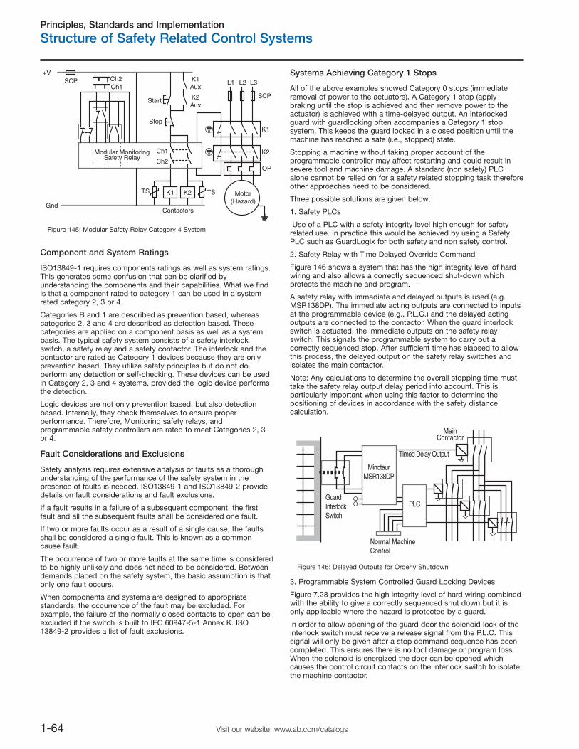
Principles, Standards and Implementation
Structure of Safety Related Control Systems
1-64 Visit our website: www.ab.com/catalogs
Component and System Ratings
ISO13849-1 requires components ratings as well as system ratings.This generates some confusion that can be clarified byunderstanding the components and their capabilities. What we findis that a component rated to category 1 can be used in a systemrated category 2, 3 or 4.
Categories B and 1 are described as prevention based, whereascategories 2, 3 and 4 are described as detection based. Thesecategories are applied on a component basis as well as a systembasis. The typical safety system consists of a safety interlockswitch, a safety relay and a safety contactor. The interlock and thecontactor are rated as Category 1 devices because they are onlyprevention based. They utilize safety principles but do not doperform any detection or self-checking. These devices can be usedin Category 2, 3 and 4 systems, provided the logic device performsthe detection.
Logic devices are not only prevention based, but also detectionbased. Internally, they check themselves to ensure properperformance. Therefore, Monitoring safety relays, andprogrammable safety controllers are rated to meet Categories 2, 3or 4.
Fault Considerations and Exclusions
Safety analysis requires extensive analysis of faults as a thoroughunderstanding of the performance of the safety system in thepresence of faults is needed. ISO13849-1 and ISO13849-2 providedetails on fault considerations and fault exclusions.
If a fault results in a failure of a subsequent component, the firstfault and all the subsequent faults shall be considered one fault.
If two or more faults occur as a result of a single cause, the faultsshall be considered a single fault. This is known as a commoncause fault.
The occurrence of two or more faults at the same time is consideredto be highly unlikely and does not need to be considered. Betweendemands placed on the safety system, the basic assumption is thatonly one fault occurs.
When components and systems are designed to appropriatestandards, the occurrence of the fault may be excluded. Forexample, the failure of the normally closed contacts to open can beexcluded if the switch is built to IEC 60947-5-1 Annex K. ISO13849-2 provides a list of fault exclusions.
Systems Achieving Category 1 Stops
All of the above examples showed Category 0 stops (immediateremoval of power to the actuators). A Category 1 stop (applybraking until the stop is achieved and then remove power to theactuator) is achieved with a time-delayed output. An interlockedguard with guardlocking often accompanies a Category 1 stopsystem. This keeps the guard locked in a closed position until themachine has reached a safe (i.e., stopped) state.
Stopping a machine without taking proper account of theprogrammable controller may affect restarting and could result insevere tool and machine damage. A standard (non safety) PLCalone cannot be relied on for a safety related stopping task thereforeother approaches need to be considered.
Three possible solutions are given below:
1. Safety PLCs
Use of a PLC with a safety integrity level high enough for safetyrelated use. In practice this would be achieved by using a SafetyPLC such as GuardLogix for both safety and non safety control.
2. Safety Relay with Time Delayed Override Command
Figure 146 shows a system that has the high integrity level of hardwiring and also allows a correctly sequenced shut-down whichprotects the machine and program.
A safety relay with immediate and delayed outputs is used (e.g.MSR138DP). The immediate acting outputs are connected to inputsat the programmable device (e.g., P.L.C.) and the delayed actingoutputs are connected to the contactor. When the guard interlockswitch is actuated, the immediate outputs on the safety relayswitch. This signals the programmable system to carry out acorrectly sequenced stop. After sufficient time has elapsed to allowthis process, the delayed output on the safety relay switches andisolates the main contactor.
Note: Any calculations to determine the overall stopping time musttake the safety relay output delay period into account. This isparticularly important when using this factor to determine thepositioning of devices in accordance with the safety distancecalculation.
GuardInterlockSwitch
MinotaurMSR138DP
Timed Delay Output
PLC
Normal MachineControl
MainContactor
Figure 146: Delayed Outputs for Orderly Shutdown
3. Programmable System Controlled Guard Locking Devices
Figure 7.28 provides the high integrity level of hard wiring combinedwith the ability to give a correctly sequenced shut down but it isonly applicable where the hazard is protected by a guard.
In order to allow opening of the guard door the solenoid lock of theinterlock switch must receive a release signal from the P.L.C. Thissignal will only be given after a stop command sequence has beencompleted. This ensures there is no tool damage or program loss.When the solenoid is energized the door can be opened whichcauses the control circuit contacts on the interlock switch to isolatethe machine contactor.
Start
K1
K2Aux
K1Aux
Motor(Hazard)
K2
K1
L1 L2 L3
Stop
K2
+V
Gnd
Modular MonitoringSafety Relay
Contactors
SCP
OP
Ch1
Ch1
Ch2
Ch2SCP
TS TS
Figure 145: Modular Safety Relay Category 4 System
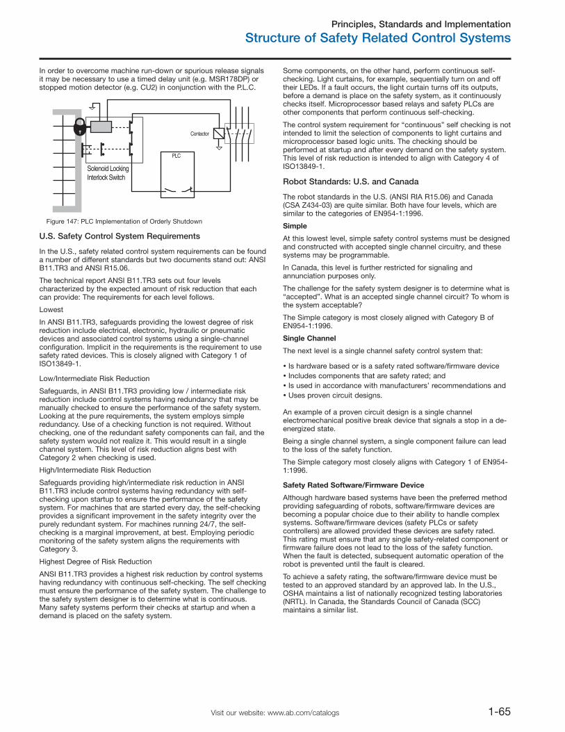
Principles, Standards and Implementation
Structure of Safety Related Control Systems
1-65Visit our website: www.ab.com/catalogs
In order to overcome machine run-down or spurious release signalsit may be necessary to use a timed delay unit (e.g. MSR178DP) orstopped motion detector (e.g. CU2) in conjunction with the P.L.C.
Solenoid LockingInterlock Switch
PLC
Contactor
Figure 147: PLC Implementation of Orderly Shutdown
U.S. Safety Control System Requirements
In the U.S., safety related control system requirements can be founda number of different standards but two documents stand out: ANSIB11.TR3 and ANSI R15.06.
The technical report ANSI B11.TR3 sets out four levelscharacterized by the expected amount of risk reduction that eachcan provide: The requirements for each level follows.
Lowest
In ANSI B11.TR3, safeguards providing the lowest degree of riskreduction include electrical, electronic, hydraulic or pneumaticdevices and associated control systems using a single-channelconfiguration. Implicit in the requirements is the requirement to usesafety rated devices. This is closely aligned with Category 1 ofISO13849-1.
Low/Intermediate Risk Reduction
Safeguards, in ANSI B11.TR3 providing low / intermediate riskreduction include control systems having redundancy that may bemanually checked to ensure the performance of the safety system.Looking at the pure requirements, the system employs simpleredundancy. Use of a checking function is not required. Withoutchecking, one of the redundant safety components can fail, and thesafety system would not realize it. This would result in a singlechannel system. This level of risk reduction aligns best withCategory 2 when checking is used.
High/Intermediate Risk Reduction
Safeguards providing high/intermediate risk reduction in ANSIB11.TR3 include control systems having redundancy with self-checking upon startup to ensure the performance of the safetysystem. For machines that are started every day, the self-checkingprovides a significant improvement in the safety integrity over thepurely redundant system. For machines running 24/7, the self-checking is a marginal improvement, at best. Employing periodicmonitoring of the safety system aligns the requirements withCategory 3.
Highest Degree of Risk Reduction
ANSI B11.TR3 provides a highest risk reduction by control systemshaving redundancy with continuous self-checking. The self checkingmust ensure the performance of the safety system. The challenge tothe safety system designer is to determine what is continuous.Many safety systems perform their checks at startup and when ademand is placed on the safety system.
Some components, on the other hand, perform continuous self-checking. Light curtains, for example, sequentially turn on and offtheir LEDs. If a fault occurs, the light curtain turns off its outputs,before a demand is place on the safety system, as it continuouslychecks itself. Microprocessor based relays and safety PLCs areother components that perform continuous self-checking.
The control system requirement for “continuous” self checking is notintended to limit the selection of components to light curtains andmicroprocessor based logic units. The checking should beperformed at startup and after every demand on the safety system.This level of risk reduction is intended to align with Category 4 ofISO13849-1.
Robot Standards: U.S. and Canada
The robot standards in the U.S. (ANSI RIA R15.06) and Canada(CSA Z434-03) are quite similar. Both have four levels, which aresimilar to the categories of EN954-1:1996.
Simple
At this lowest level, simple safety control systems must be designedand constructed with accepted single channel circuitry, and thesesystems may be programmable.
In Canada, this level is further restricted for signaling andannunciation purposes only.
The challenge for the safety system designer is to determine what is“accepted”. What is an accepted single channel circuit? To whom isthe system acceptable?
The Simple category is most closely aligned with Category B ofEN954-1:1996.
Single Channel
The next level is a single channel safety control system that:
Is hardware based or is a safety rated software/firmware deviceIncludes components that are safety rated; andIs used in accordance with manufacturers’ recommendations andUses proven circuit designs.
An example of a proven circuit design is a single channelelectromechanical positive break device that signals a stop in a de-energized state.
Being a single channel system, a single component failure can leadto the loss of the safety function.
The Simple category most closely aligns with Category 1 of EN954-1:1996.
Safety Rated Software/Firmware Device
Although hardware based systems have been the preferred methodproviding safeguarding of robots, software/firmware devices arebecoming a popular choice due to their ability to handle complexsystems. Software/firmware devices (safety PLCs or safetycontrollers) are allowed provided these devices are safety rated.This rating must ensure that any single safety-related component orfirmware failure does not lead to the loss of the safety function.When the fault is detected, subsequent automatic operation of therobot is prevented until the fault is cleared.
To achieve a safety rating, the software/firmware device must betested to an approved standard by an approved lab. In the U.S.,OSHA maintains a list of nationally recognized testing laboratories(NRTL). In Canada, the Standards Council of Canada (SCC)maintains a similar list.
Principles, Standards and Implementation
Functional Safety of Control Systems
1-66 Visit our website: www.ab.com/catalogs
Single Channel with Monitoring
Single channel safety control systems with monitoring must fulfill therequirements for single channel; be safety rated and utilizechecking. The check of the safety function(s) must be performed atmachine start-up, and periodically during operation. Automaticchecking is preferred over manual checking.
The checking operation allows operation if no faults have beendetected or generates a stop signal if a fault is detected. A warningmust be provided if a hazard remains after cessation of motion. Ofcourse, the check itself must not cause a hazardous situation. Afterdetecting the fault, the robot must remain in a safe state until thefault is corrected.
Single Channel with Monitoring most closely aligns with Category 2of EN954-1:1996.
Control Reliable
The highest level of risk reduction in the US and Canadian robotstandards is achieved by safety related control systems meeting therequirements of Control Reliable. Control reliable safety relatedcontrol systems are dual channel architectures with monitoring. Thestopping function of the robot must not be prevented by any singlecomponent failure, including the monitoring function.
The monitoring shall generate a stop command upon detection of afault. If a hazard remains after motion stops, a warning signal mustbe provided. The safety system must remain in a safe state until thefault is corrected.
Preferably, the fault is detected at the time of the failure. If thiscannot be achieved, then the failure must be detected at the nextdemand on the safety system.
Common mode failures must be taken into consideration if asignificant probability of such a failure can occur.
The Canadian requirements differ from the U.S. requirement byadding two additional requirements. First, the safety related controlsystems shall be independent of the normal program controlsystems. Second, the safety system must not be easily defeated orbypassed without detection.
Control reliable systems align with Category 4 of EN1954-1:1996.
Comments on Control Reliable:
The most fundamental aspect of Control Reliable is single faulttolerance. The requirements state how the safety system mustrespond in the presence of “a single fault,” “any single fault,” or“any single component failure.”
Three very important concepts must considered regarding faults: 1)not all faults are detected, and 2) adding the word “component”raises questions about wiring. Wiring is an integral part of the safetysystem, and wiring faults can result in the loss of a safety function.
The intent of Control Reliability is clearly the performance of thesafety function in the presence of a fault. If the fault is detected,then the safety system must execute a safe action, providenotification of the fault, and prevent further operation of the machineuntil the fault is corrected. If the fault is not detected, then the safetyfunction must still be performed upon demand.
Introduction to Functional Safety ofControl SystemsImportant: The standards and requirements considered in thissection are relatively new. Work is still being carried in the standardswriting groups on some aspects especially with regard toclarification and combining some of the standards. Therefore it islikely that during the period of 2007/8 there will be some changes tosome of the detail given in these pages. For the latest informationplease refer to the Rockwell Automation safety systems andcomponents website at http://www.ab.com/safety.
A New Direction
At the time of publication of this catalog there is an increasingawareness of the implications of a new generation of standards thatcover the functional safety of safety related control systems anddevices.
Functional safety is the part of the overall safety that depends onthe correct functioning of the process or equipment.
Therefore the functional safety of an electrical control system ishighly relevant to the control of hazards arising from moving parts ofmachinery.
Three of the most significant control system functional safetystandards for machinery are:
IEC/EN 61508 “Functional safety of safety related electrical,electronic and programmable electronic control systems”
This standard contains the requirements and provisions that areapplicable to the design of complex electronic and programmablesystems and subsystems. The standard is generic so it is notrestricted to the machinery sector.
IEC/EN 62061”Safety of machinery - Functional safety of safetyrelated electrical, electronic and programmable electronic controlsystems”
It is the machinery specific implementation of IEC/EN 61508. Itprovides requirements that are applicable to the system level designof all types of machinery safety related electrical control systemsand also for the design of non-complex subsystems or devices. Itrequires that complex or programmable subsystems should satisfyIEC/EN 61508
ISO/EN 13849-1:2006 ”Safety of machinery – Safety related parts ofcontrol systems”
Intended to provide a functional safety transition path from the useof Categories.
The functional safety standards represent a significant step beyondthe familiar existing requirements such as Control Reliable and theCategories system of ISO 13849-1 (EN 954-1). Categories are notdisappearing yet, the original standard will remain valid until 2010 toprovide a period for transition to its new revised version. This newversion of ISO/EN 13849-1 uses the functional safety concept andhas introduced new terminology and requirements. In this sectionwe will refer to the new version as ISO/EN 13849-1:2006.
Interest in the functional safety standards will grow because they arethe future and they facilitate more flexibility and the use of newtechnology for machinery safety.
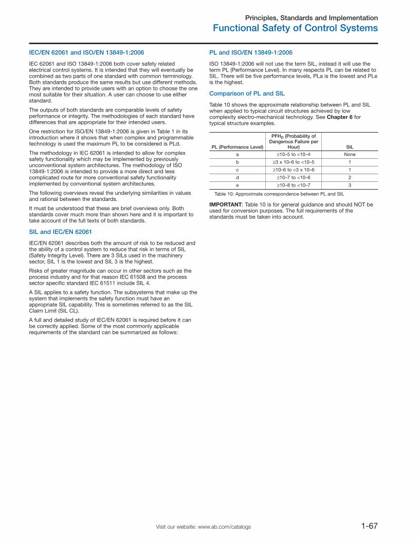
Principles, Standards and Implementation
Functional Safety of Control Systems
1-67Visit our website: www.ab.com/catalogs
IEC/EN 62061 and ISO/EN 13849-1:2006
IEC 62061 and ISO 13849-1:2006 both cover safety relatedelectrical control systems. It is intended that they will eventually becombined as two parts of one standard with common terminology.Both standards produce the same results but use different methods.They are intended to provide users with an option to choose the onemost suitable for their situation. A user can choose to use eitherstandard.
The outputs of both standards are comparable levels of safetyperformance or integrity. The methodologies of each standard havedifferences that are appropriate for their intended users.
One restriction for ISO/EN 13849-1:2006 is given in Table 1 in itsintroduction where it shows that when complex and programmabletechnology is used the maximum PL to be considered is PLd.
The methodology in IEC 62061 is intended to allow for complexsafety functionality which may be implemented by previouslyunconventional system architectures. The methodology of ISO13849-1:2006 is intended to provide a more direct and lesscomplicated route for more conventional safety functionalityimplemented by conventional system architectures.
The following overviews reveal the underlying similarities in valuesand rational between the standards.
It must be understood that these are brief overviews only. Bothstandards cover much more than shown here and it is important totake account of the full texts of both standards.
SIL and IEC/EN 62061
IEC/EN 62061 describes both the amount of risk to be reduced andthe ability of a control system to reduce that risk in terms of SIL(Safety Integrity Level). There are 3 SILs used in the machinerysector, SIL 1 is the lowest and SIL 3 is the highest.
Risks of greater magnitude can occur in other sectors such as theprocess industry and for that reason IEC 61508 and the processsector specific standard IEC 61511 include SIL 4.
A SIL applies to a safety function. The subsystems that make up thesystem that implements the safety function must have anappropriate SIL capability. This is sometimes referred to as the SILClaim Limit (SIL CL).
A full and detailed study of IEC/EN 62061 is required before it canbe correctly applied. Some of the most commonly applicablerequirements of the standard can be summarized as follows:
PL and ISO/EN 13849-1:2006
ISO 13849-1:2006 will not use the term SIL, instead it will use theterm PL (Performance Level). In many respects PL can be related toSIL. There will be five performance levels, PLa is the lowest and PLeis the highest.
Comparison of PL and SIL
Table 10 shows the approximate relationship between PL and SILwhen applied to typical circuit structures achieved by lowcomplexity electro-mechanical technology. See Chapter 6 fortypical structure examples.
PL (Performance Level)
PFHD (Probability ofDangerous Failure per
Hour) SIL
a ≥10–5 to <10–4 None
b ≥3 x 10⁻⁶ to <10–5 1
c ≥10–6 to <3 x 10⁻⁶ 1
d ≥10–7 to <10–6 2
e ≥10–8 to <10–7 3
Table 10: Approximate correspondence between PL and SIL
IMPORTANT: Table 10 is for general guidance and should NOT beused for conversion purposes. The full requirements of thestandards must be taken into account.
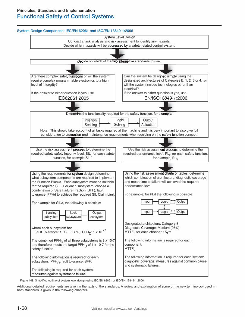
Principles, Standards and Implementation
Functional Safety of Control Systems
1-68 Visit our website: www.ab.com/catalogs
System Design Comparison: IEC/EN 62061 and ISO/EN 13849-1:2006
Additional detailed requirements are given in the texts of the standards. A review and explanation of some of the new terminology used inboth standards is given in the following chapters.
System Level DesignConduct a task analysis and risk assessment to identify any hazards.
Decide which hazards will be addressed by a safety related control system.
Are there complex safety functions or will the systemrequire complex programmable electronics to a highlevel of intergrity?
If the answer to either question is yes, use
IEC62061:2005
Can the system be designed simply using thedesignated architectures of Categoies B, 1, 2, 3 or 4, orwill the system include technologies other than electrical?If the answer to either question is yes, use
EN/ISO13849-1:2006
Determine the functionality required for the safety function, for ex
Note: This should take account of all tasks required at the machine and it is very important to also give full consideration to production and maintenance requirements when deciding on the safety function concept.
PositionSensing
LogicSolving
OutputActuation
Use the risk assessment process to determine therequired safety safety integrity level, SIL, for each safety
function, for example SIL2
Use the risk assessment process to determine therequired performance level, PLr, for each safety function,
for example, PLd
Using the requirements for system design determine what subsystem components are required to implement the Function Blocks. Each subsystem must be suitable for the required SIL. For each subsystem, choose a combination of Safe Failure Fraction (SFF), fault tolerance, PFHd to achieve the required SIL Claim Limit.
For example for SIL3, the following is possible:
where each subsystem has Fault Tolerance: 1, SFF: 80%, PFHD: 1 x 10 -7
The combined PFHD of all three subsystems is 3 x 10⁻⁷ and therefore meets the target PFHD of 1 x 10⁻⁷ for the safety function.
The following information is required for each subsystem: PFHD, fault tolerance, SFF.
The following is required for each system:measures against systematic failure.
Using the risk assessment charts or tables, determine which combination of architecture, diagnostic coverageand mean time to failure will achieved the required performance level.
For example, for PLd the following is possible
Designated architecture: Category 3Diagnostic Coverage: Medium (95%)MTTFd for each channel: 15yrs
The following information is required for each component:MTTFd
The following information is reqiured for each system:diagnostic coverage, measures against common cause and systematic failures.
Sensingsubsystem
Logicsubsystem
Outputsubsytem
Input Logic Output
Input Logic Output
Decide on which of the two alternative standards to use.
Figure 148: Simplified outline of system level design using IEC/EN 62061 or ISO/EN 13849-1:2006.
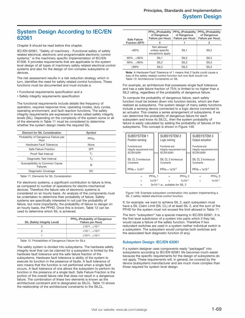
Principles, Standards and Implementation
System Design
1-69Visit our website: www.ab.com/catalogs
System Design According to IEC/EN62061Chapter 8 should be read before this chapter.
IEC/EN 62061, ”Safety of machinery - Functional safety of safetyrelated electrical, electronic and programmable electronic controlsystems,” is the machinery specific implementation of IEC/EN61508. It provides requirements that are applicable to the systemlevel design of all types of machinery safety related electrical controlsystems and also for the design of non-complex subsystems ordevices.
The risk assessment results in a risk reduction strategy which inturn, identifies the need for safety related control functions. Thesefunctions must be documented and must include a:
Functional requirements specification and aSafety integrity requirements specification
The functional requirements include details like frequency ofoperation, required response time, operating modes, duty cycles,operating environment, and fault reaction functions. The safetyintegrity requirements are expressed in levels called safety integritylevels (SIL). Depending on the complexity of the system some or allof the elements in Table 11 must be considered to determinewhether the system design meets the required SIL.
Element for SIL Consideration Symbol
Probability of Dangerous Failure perHour
PFHD
Hardware Fault Tolerance None
Safe Failure Fraction SFF
Proof Test Interval T1
Diagnostic Test Interval T2
Susceptibility to Common CauseFailures B
Diagnostic Coverage DC
Table 11: Elements for SIL Consideration
For electronic systems, a significant contribution to failure is time,as compared to number of operations for electro-mechanicaldevices. Therefore the failure rate of electronic systems isconsidered on an hourly basis. An analysis of the components mustbe undertaken to determine their probability of failure. Safetysystems are specifically interested in not just the probability offailure, but more importantly, the probability of failure to danger onan hourly basis, the PFHD. Once this is known, Table 12 can beused to determine which SIL is achieved.
SIL (Safety Integrity Level)PFHD (Probability of Dangerous
Failure per Hour)
3 ≥10–8…<10–7
2 ≥10–7…<10-6
1 ≥10–6…<10–5
Table 12: Probabilities of Dangerous Failure for SILs
The safety system is divided into subsystems. The hardware safetyintegrity level that can be claimed for a subsystem is limited by thehardware fault tolerance and the safe failure fraction of thesubsystems. Hardware fault tolerance is ability of the system toexecute its function in the presence of faults. A fault tolerance ofzero means that the function is not performed when a single faultoccurs. A fault tolerance of one allows the subsystem to perform itsfunction in the presence of a single fault. Safe Failure Fraction is theportion of the overall failure rate that does not result in a dangerousfailure. The combination of these two elements is known as thearchitectural constraint and is designated as SILCL. Table 13 showsthe relationship of the architectural constraints to the SILCL.
For example, an architecture that possesses single fault toleranceand has a safe failure fraction of 75% is limited to no higher than aSIL2 rating, regardless of the probability of dangerous failure.
To compute the probability of dangerous failure, each safetyfunction must be broken down into function blocks, which are thenrealized as subsystems. The system design of many safety functionsinclude a sensing device connected to a logic device connected toan actuator. This creates a series arrangement of subsystems. If wecan determine the probability of dangerous failure for eachsubsystem and know its SILCL, then the system probability offailure is easily calculated by adding the probability of failures of thesubsystems. This concept is shown in Figure 149.
Safe FailureFraction (SFF)
PFHD (Probabilityof Dangerous
Failure per Hour)
PFHD (Probabilityof Dangerous
Failure per Hour)
PFHD (Probabilityof Dangerous
Failure per Hour)
0 1 2
<60%Not allowed
unless specificexceptions apply
SIL1 SIL2
60%…<90% SIL1 SIL2 SIL3
90%…<99% SIL2 SIL3 SIL3
≥99% SIL3 SIL3 SIL3
Note: A Hardware Fault Tolerance of 1 means that 2 faults could cause aloss of the safety related control function but one fault would not.Table 13: Architectural Constraints on SIL
SUBSYSTEM 1Position sensing
Functional and Integrity requirements from IEC/EN 62061
SIL CL 2 Architectural Constraints
PFHD = 1x10⁻⁷
SUBSYSTEM 3Output actuation
Functional and Integrity requirements from IEC/EN 62061
SIL CL 2 Architectural Constraints
PFHD = 1x10⁻⁷
SUBSYSTEM 2Logic solving
Functional and Integrity requirements from IEC/EN 62061
SIL CL 2 Architectural Constraints
PFHD = 1x10-7
= PFHD 1 + PFHD 2 + PFHD 3
= 1x10⁻⁷ + 1x10⁻⁷ + 1x10-7
= 3x10⁻⁷ i.e., suitable for SIL 2
Figure 149: Example subsystem combination into system implementing aSIL 2 safety related electrical control function.
If, for example, we want to achieve SIL 2, each subsystem musthave a SIL Claim Limit (SIL CL) of at least SIL 2, and the sum of thePFHD for the system must not exceed the limit allowed in Table 11.
The term “subsystem” has a special meaning in IEC/EN 62061. It isthe first level subdivision of a system into parts which if they fail,would cause a failure of the safety function. Therefore if tworedundant switches are used in a system neither individual switch isa subsystem. The subsystem would comprise both switches andthe associated fault diagnostic function (if any).
Subsystem Design: IEC/EN 62061
If a system designer uses components ready “packaged” intosubsystems according to IEC/EN 62061 life becomes much easierbecause the specific requirements for the design of subsystems donot apply. These requirements will, in general, be covered by thedevice (subsystem) manufacturer and are much more complex thanthose required for system level design.
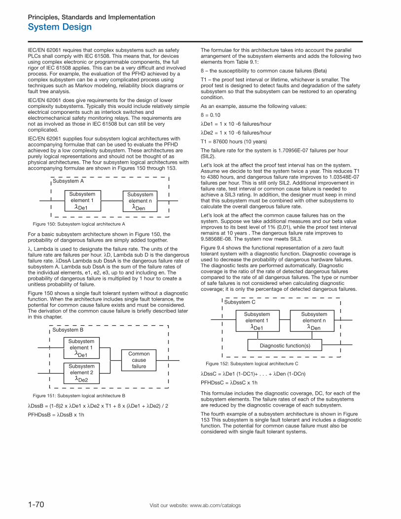
Principles, Standards and Implementation
System Design
1-70 Visit our website: www.ab.com/catalogs
IEC/EN 62061 requires that complex subsystems such as safetyPLCs shall comply with IEC 61508. This means that, for devicesusing complex electronic or programmable components, the fullrigor of IEC 61508 applies. This can be a very difficult and involvedprocess. For example, the evaluation of the PFHD achieved by acomplex subsystem can be a very complicated process usingtechniques such as Markov modeling, reliability block diagrams orfault tree analysis.
IEC/EN 62061 does give requirements for the design of lowercomplexity subsystems. Typically this would include relatively simpleelectrical components such as interlock switches andelectromechanical safety monitoring relays. The requirements arenot as involved as those in IEC 61508 but can still be verycomplicated.
IEC/EN 62061 supplies four subsystem logical architectures withaccompanying formulae that can be used to evaluate the PFHDachieved by a low complexity subsystem. These architectures arepurely logical representations and should not be thought of asphysical architectures. The four subsystem logical architectures withaccompanying formulae are shown in Figures 150 through 153.
Subsystem A
Subsystemelement 1
De1
Subsystemelement n
Den
Figure 150: Subsystem logical architecture A
For a basic subsystem architecture shown in Figure 150, theprobability of dangerous failures are simply added together.
λ, Lambda is used to designate the failure rate. The units of thefailure rate are failures per hour. λD, Lambda sub D is the dangerousfailure rate. λDssA Lambda sub DssA is the dangerous failure rate ofsubsystem A. Lambda sub DssA is the sum of the failure rates ofthe individual elements, e1, e2, e3, up to and including en. Theprobability of dangerous failure is multiplied by 1 hour to create aunitless probability of failure.
Figure 150 shows a single fault tolerant system without a diagnosticfunction. When the architecture includes single fault tolerance, thepotential for common cause failure exists and must be considered.The derivation of the common cause failure is briefly described laterin this chapter.
Subsystem B
Subsystemelement 1
De1 CommoncausefailureSubsystem
element 2
De2
Figure 151: Subsystem logical architecture B
λDssB = (1-ß)2 x λDe1 x λDe2 x T1 + ß x (λDe1 + λDe2) / 2
PFHDssB = λDssB x 1h
The formulae for this architecture takes into account the parallelarrangement of the subsystem elements and adds the following twoelements from Table 9.1:
ß – the susceptibility to common cause failures (Beta)
T1 – the proof test interval or lifetime, whichever is smaller. Theproof test is designed to detect faults and degradation of the safetysubsystem so that the subsystem can be restored to an operatingcondition.
As an example, assume the following values:
ß = 0.10
λDe1 = 1 x 10 -6 failures/hour
λDe2 = 1 x 10 -6 failures/hour
T1 = 87600 hours (10 years)
The failure rate for the system is 1.70956E-07 failures per hour(SIL2).
Let’s look at the affect the proof test interval has on the system.Assume we decide to test the system twice a year. This reduces T1to 4380 hours, and dangerous failure rate improves to 1.03548E-07failures per hour. This is still only SIL2. Additional improvement infailure rate, test interval or common cause failure is needed toachieve a SIL3 rating. In addition, the designer must keep in mindthat this subsystem must be combined with other subsystems tocalculate the overall dangerous failure rate.
Let’s look at the affect the common cause failures has on thesystem. Suppose we take additional measures and our beta valueimproves to its best level of 1% (0,01), while the proof test intervalremains at 10 years . The dangerous failure rate improves to9.58568E-08. The system now meets SIL3.
Figure 9.4 shows the functional representation of a zero faulttolerant system with a diagnostic function. Diagnostic coverage isused to decrease the probability of dangerous hardware failures.The diagnostic tests are performed automatically. Diagnosticcoverage is the ratio of the rate of detected dangerous failurescompared to the rate of all dangerous failures. The type or numberof safe failures is not considered when calculating diagnosticcoverage; it is only the percentage of detected dangerous failures.
Subsystem C
Subsystemelement 1
De1
Diagnostic function(s)
Subsystemelement n
Den
Figure 152: Subsystem logical architecture C
λDssC = λDe1 (1-DC1)+ . . . + λDen (1-DCn)
PFHDssC = λDssC x 1h
This formulae includes the diagnostic coverage, DC, for each of thesubsystem elements. The failure rates of each of the subsystemsare reduced by the diagnostic coverage of each subsystem.
The fourth example of a subsystem architecture is shown in Figure153 This subsystem is single fault tolerant and includes a diagnosticfunction. The potential for common cause failure must also beconsidered with single fault tolerant systems.
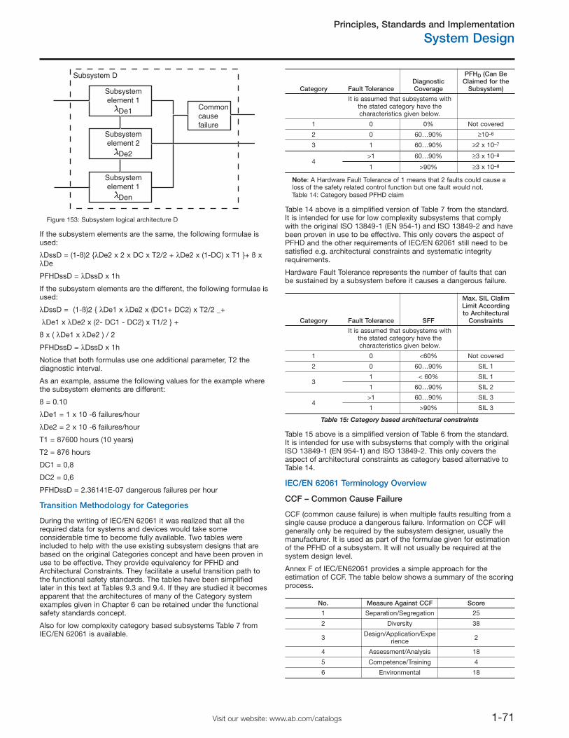
Principles, Standards and Implementation
System Design
1-71Visit our website: www.ab.com/catalogs
Subsystem D
Subsystemelement 1
De1 Commoncausefailure
Subsystemelement 2
De2
Subsystemelement 1
Den
Figure 153: Subsystem logical architecture D
If the subsystem elements are the same, the following formulae isused:
λDssD = (1-ß)2 {λDe2 x 2 x DC x T2/2 + λDe2 x (1-DC) x T1 }+ ß xλDe
PFHDssD = λDssD x 1h
If the subsystem elements are the different, the following formulae isused:
λDssD = (1-ß)2 { λDe1 x λDe2 x (DC1+ DC2) x T2/2 _+
λDe1 x λDe2 x (2- DC1 - DC2) x T1/2 } +
ß x ( λDe1 x λDe2 ) / 2
PFHDssD = λDssD x 1h
Notice that both formulas use one additional parameter, T2 thediagnostic interval.
As an example, assume the following values for the example wherethe subsystem elements are different:
ß = 0.10
λDe1 = 1 x 10 -6 failures/hour
λDe2 = 2 x 10 -6 failures/hour
T1 = 87600 hours (10 years)
T2 = 876 hours
DC1 = 0,8
DC2 = 0,6
PFHDssD = 2.36141E-07 dangerous failures per hour
Transition Methodology for Categories
During the writing of IEC/EN 62061 it was realized that all therequired data for systems and devices would take someconsiderable time to become fully available. Two tables wereincluded to help with the use existing subsystem designs that arebased on the original Categories concept and have been proven inuse to be effective. They provide equivalency for PFHD andArchitectural Constraints. They facilitate a useful transition path tothe functional safety standards. The tables have been simplifiedlater in this text at Tables 9.3 and 9.4. If they are studied it becomesapparent that the architectures of many of the Category systemexamples given in Chapter 6 can be retained under the functionalsafety standards concept.
Also for low complexity category based subsystems Table 7 fromIEC/EN 62061 is available.
Category Fault ToleranceDiagnosticCoverage
PFHD (Can BeClaimed for the
Subsystem)
It is assumed that subsystems withthe stated category have thecharacteristics given below.
1 0 0% Not covered
2 0 60…90% ≥10–6
3 1 60…90% ≥2 x 10⁻⁷
4>1 60…90% ≥3 x 10⁻⁸
1 >90% ≥3 x 10⁻⁸
Note: A Hardware Fault Tolerance of 1 means that 2 faults could cause aloss of the safety related control function but one fault would not.Table 14: Category based PFHD claim
Table 14 above is a simplified version of Table 7 from the standard.It is intended for use for low complexity subsystems that complywith the original ISO 13849-1 (EN 954-1) and ISO 13849-2 and havebeen proven in use to be effective. This only covers the aspect ofPFHD and the other requirements of IEC/EN 62061 still need to besatisfied e.g. architectural constraints and systematic integrityrequirements.
Hardware Fault Tolerance represents the number of faults that canbe sustained by a subsystem before it causes a dangerous failure.
Category Fault Tolerance SFF
Max. SIL ClalimLimit Accordingto Architectural
Constraints
It is assumed that subsystems withthe stated category have thecharacteristics given below.
1 0 <60% Not covered
2 0 60…90% SIL 1
31 < 60% SIL 1
1 60…90% SIL 2
4>1 60…90% SIL 3
1 >90% SIL 3
Table 15: Category based architectural constraints
Table 15 above is a simplified version of Table 6 from the standard.It is intended for use with subsystems that comply with the originalISO 13849-1 (EN 954-1) and ISO 13849-2. This only covers theaspect of architectural constraints as category based alternative toTable 14.
IEC/EN 62061 Terminology Overview
CCF – Common Cause Failure
CCF (common cause failure) is when multiple faults resulting from asingle cause produce a dangerous failure. Information on CCF willgenerally only be required by the subsystem designer, usually themanufacturer. It is used as part of the formulae given for estimationof the PFHD of a subsystem. It will not usually be required at thesystem design level.
Annex F of IEC/EN62061 provides a simple approach for theestimation of CCF. The table below shows a summary of the scoringprocess.
No. Measure Against CCF Score
1 Separation/Segregation 25
2 Diversity 38
3 Design/Application/Experience 2
4 Assessment/Analysis 18
5 Competence/Training 4
6 Environmental 18
Principles, Standards and Implementation
System Design
1-72 Visit our website: www.ab.com/catalogs
The score is added up to determine the common cause failurefactor.
Overall Score Common Cause Failure Factor (ß)
<35 10% (0.1)
35…65 5% (0.05)
65…85 2% (0.02)
85…100 1% (0.01)
DC (Diagnostic Coverage)
Automatic diagnostic tests are employed to decrease the probabilityof dangerous hardware failures. Being able to detect 100% of thedangerous hardware failures would be ideal, but is often verydifficult to accomplish.
Diagnostic coverage is the ratio of the detected dangerous failuresto all the dangerous failures.
Rate of Detected dangerous failures, λDD
DC = -------------------------------------------------------
Rate of Total dangerous failures, λDtotal
The value of diagnostic coverage will lie between zero and one.
Management of Functional Safety
The standard gives requirements for the control of management andtechnical activities that are necessary for the achievement of asafety related electrical control system.
PFHD (Probability of Dangerous Failure)
Part of the requirements needed to achieve any given SIL capabilityfor a system or subsystem is data on PFHD (probability of adangerous failure per hour) due to random hardware failure. Table7.3 gives the probability ranges for each SIL.
This data will be provided by the manufacturer. Data for recentRockwell Automation safety components and systems (e.g.GuardLogix, GuardPLC, SmartGuard, Kinetix with GuardMotion) isalready available. Data for other Rockwell Automation safetycomponents and systems will become available during 2007.
IEC/EN 62061 also makes it clear that reliability data handbooks canbe used if and where applicable.
For low complexity electromechanical devices, the failuremechanism is usually linked to the number and frequency ofoperations rather than just time. Therefore for these components thedata will derived from some form of lifetime testing e.g. B10 testing.Application based information such as the anticipated number oroperations per year is then required in order to convert the B10d orsimilar data to MTTFd (Mean Time To Dangerous Failure). This, inturn, is then converted to PFHd.
In general the following can be assumed:
PFHD = 1/MTTFd
And, for electromechanical devices:
MTTFd = B10d /(0.1 x mean number of operations per year)
Proof Test Interval
This will be declared by the manufacturer and represents the timeafter which a subsystem must be either totally checked to ensurethat it is in the as new condition. In practice, in the machinerysector, this is achieved by replacement. So the proof test interval ususually the same thing as lifetime. ISO 13849-1:2006 refers to thisas Mission Time.
SFF (Safe Failure Fraction)
SFF (Safe Failure Fraction) is similar to Diagnostic Coverage (DC)but also takes account of any inherent tendency to fail towards asafe state. For example, when a fuse blows, there is a failure but itis highly probable that the failure will be to an open circuit which, inmost cases, would be a “safe” failure. SFF is (the sum of the rate of“safe” failures plus the rate of detected dangerous failures) dividedby (the sum of the rate of “safe” failures plus the rate of detectedand undetected dangerous failures). It is important to realize that theonly types of failures to be considered are those which could havesome affect on the safety function.
Most low complexity mechanical devices such as E-stop buttonsand interlock switches will (on their own)have an SFF of less than60% but most electronic devices for safety have designed inredundancy and monitoring therefore an SFF of greater than 90% iscommon. The SFF value will normally be supplied by themanufacturer.
The Safe Failure Fraction (SFF) can be calculated using thefollowing equation:
SFF = (Σλ S + Σλ DD) / (Σλ S + Σλ D)
where
λ S = the rate of safe failure,
Σλ S + Σλ D = the overall failure rate,
λ DD = the rate of detected dangerous failure
λ D = the rate of dangerous failure.
Systematic Failure
The standard has requirements for the control and avoidance ofsystematic failure. The standards differentiate systematic failuresfrom random hardware failures which are failures occurring at arandom time, typically resulting from degradation of parts ofhardware.
Typical types of possible systematic failure are software designerrors, hardware design errors, requirement specification errors andoperational procedures. Examples of steps necessary to avoidsystematic failure include:
Proper selection, combination, arrangements, assembly andinstallation of components,Use of good engineering practice,Follow manufacturer’s specifications and installation instructions,Ensuring compatibility between components,Withstanding environmental conditions,Use of suitable materials.
The standard provides additional and more detailed requirementsneeded to avoid systematic failures. The standard does not containa scoring system to determine what percentage of the potentialsystematic failures are covered. To meet the requirements of SIL3,the designer must satisfy all the requirements for avoidingsystematic failure. If not all requirements are met, then the SIL ClaimLimit must be reduced.
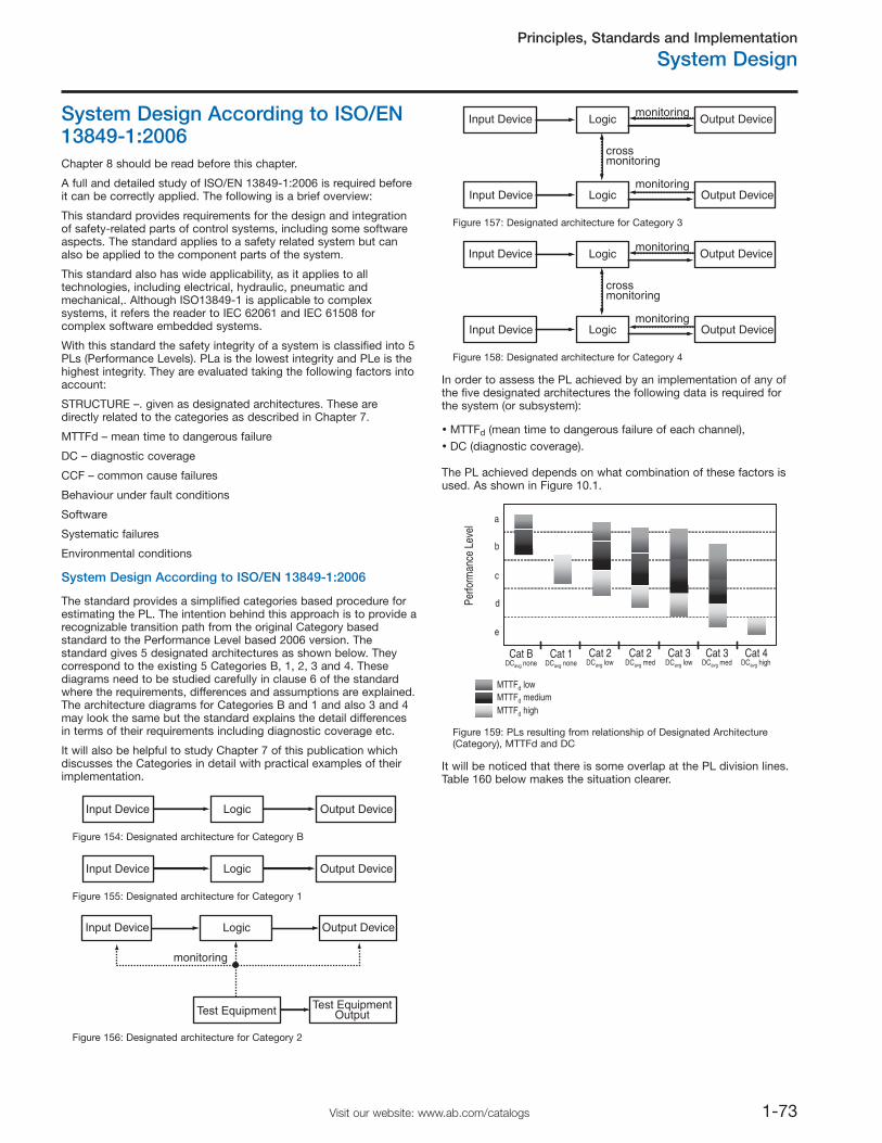
Principles, Standards and Implementation
System Design
1-73Visit our website: www.ab.com/catalogs
System Design According to ISO/EN13849-1:2006Chapter 8 should be read before this chapter.
A full and detailed study of ISO/EN 13849-1:2006 is required beforeit can be correctly applied. The following is a brief overview:
This standard provides requirements for the design and integrationof safety-related parts of control systems, including some softwareaspects. The standard applies to a safety related system but canalso be applied to the component parts of the system.
This standard also has wide applicability, as it applies to alltechnologies, including electrical, hydraulic, pneumatic andmechanical,. Although ISO13849-1 is applicable to complexsystems, it refers the reader to IEC 62061 and IEC 61508 forcomplex software embedded systems.
With this standard the safety integrity of a system is classified into 5PLs (Performance Levels). PLa is the lowest integrity and PLe is thehighest integrity. They are evaluated taking the following factors intoaccount:
STRUCTURE –. given as designated architectures. These aredirectly related to the categories as described in Chapter 7.
MTTFd – mean time to dangerous failure
DC – diagnostic coverage
CCF – common cause failures
Behaviour under fault conditions
Software
Systematic failures
Environmental conditions
System Design According to ISO/EN 13849-1:2006
The standard provides a simplified categories based procedure forestimating the PL. The intention behind this approach is to provide arecognizable transition path from the original Category basedstandard to the Performance Level based 2006 version. Thestandard gives 5 designated architectures as shown below. Theycorrespond to the existing 5 Categories B, 1, 2, 3 and 4. Thesediagrams need to be studied carefully in clause 6 of the standardwhere the requirements, differences and assumptions are explained.The architecture diagrams for Categories B and 1 and also 3 and 4may look the same but the standard explains the detail differencesin terms of their requirements including diagnostic coverage etc.
It will also be helpful to study Chapter 7 of this publication whichdiscusses the Categories in detail with practical examples of theirimplementation.
Input Device Logic Output Device
Figure 154: Designated architecture for Category B
Input Device Logic Output Device
Figure 155: Designated architecture for Category 1
Input Device Logic
Test Equipment
Output Device
Test EquipmentOutput
monitoring
Figure 156: Designated architecture for Category 2
Input Device Logic Output Devicemonitoring
crossmonitoring
monitoringInput Device Logic Output Device
Figure 157: Designated architecture for Category 3
Input Device Logic Output Devicemonitoring
crossmonitoring
monitoringInput Device Logic Output Device
Figure 158: Designated architecture for Category 4
In order to assess the PL achieved by an implementation of any ofthe five designated architectures the following data is required forthe system (or subsystem):
MTTFd (mean time to dangerous failure of each channel),DC (diagnostic coverage).
The PL achieved depends on what combination of these factors isused. As shown in Figure 10.1.
Cat BDCavg none
Cat 1DCavg none
Cat 2DCavg low
Cat 2DCavg med
Cat 3DCavg low
Cat 3DCavg med
Cat 4DCavg high
a
d
e
c
b
Perfo
rman
ce L
evel
MTTFd lowMTTFd mediumMTTFd high
Figure 159: PLs resulting from relationship of Designated Architecture(Category), MTTFd and DC
It will be noticed that there is some overlap at the PL division lines.Table 160 below makes the situation clearer.
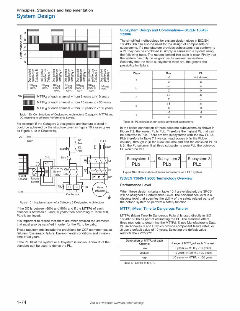
Principles, Standards and Implementation
System Design
1-74 Visit our website: www.ab.com/catalogs
Per
form
ance
leve
l
Des
igna
ted
arch
itect
ure
Cat
egor
y B
DCavg<60%
Des
igna
ted
arch
itect
ure
Cat
egor
y 1
DCavg<60%
Des
igna
ted
arch
itect
ure
Cat
egor
y 2
DCavg60% to<90%
Des
igna
ted
arch
itect
ure
Cat
egor
y 2
DCavg90% to <99%
Des
igna
ted
arch
itect
ure
Cat
egor
y 3
DCavg60% to <90%
Des
igna
ted
arch
itect
ure
Cat
egor
y 3
DCavg90% to <99%
Des
igna
ted
arch
itect
ure
Cat
egor
y 4
DCavg99%
b
a
c
d
e
Key MTTFd of each channel = from 3 years to <10 years
MTTFd of each channel = from 10 years to <30 years
MTTFd of each channel = from 30 years to <100 years
Table 160: Combinations of Designated Architecture (Category), MTTFd andDC resulting in different Performance Levels.
For example if the Category 3 designated architecture is used itcould be achieved by the structure given in Figure 10.2 (also givesas Figure 6.10 in Chapter 6).
Start
K1
GuardClosed Tongue
Switch
K2Aux
K1Aux
Motor(Hazard)
K2
K1
L1 L2 L3
Stop
K2
+V
ContactorsGnd
MonitoringSafetyRelay
SCP
SCP
OP
Ch1
Ch1
Ch2
Ch2
TS TS
Figure 161: Implementation of a Category 3 Designated Architecture
If the DC is between 60% and 90% and if the MTTFd of eachchannel is between 10 and 30 years then according to Table 160,PL e is achieved.
It is important to realize that there are other detailed requirementsthat must also be satisfied in order for the PL to be valid.
These requirements include the provisions for CCF (common causefailures), Systematic failure, Environmental conditions and missiontime of 20 years.
If the PFHD of the system or subsystem is known, Annex K of thestandard can be used to derive the PL.
Subsystem Design and Combination—ISO/EN 13849-1:2006
The simplified methodology for system design given in ISO/EN13849:2006 can also be used for the design of components orsubsystems. If a manufacture provides subsystems that conform toa PL they can be combined in simply in series into a system usingthe following table. The rational behind this table is clear. Firstly thatthe system can only be as good as its weakest subsystem.Secondly that the more subsystems there are, the greater thepossibility for failure.
PLlow Nlow PL
a>3 Not allowed.3 a
b>2 a.2 b
c>2 b.2 c
d>3 c.3 d
e>3 d.3 e
Table 16: PL calculation for series combined subsystems
In the series connection of three separate subsystems as shown inFigure 7.2, the lowest PL is PLb. Therefore the highest PL that canbe achieved is PLb. There are two subsystems with the low PL i.e.PLb therefore in Table 7.1 we can read across b (in the PLlowcolumn), through 2 (in the Nlow column) and find the achieved PL asb (in the PL column). If all three subsystems were PLb the achievedPL would be PLa.
Subsystem 2
PLb PLbSubsystem 1 Subsystem 3
PLc
Figure 162: Combination of series subsystems as a PLb system
ISO/EN 13849-1:2006 Terminology Overview
Performance Level
When these design criteria in table 10.1 are evaluated, the SRCSwill be assigned a Performance Level. The performance level is adiscrete level that specifies the ability of the safety related parts ofthe cotnorl system to perform a safety function.
MTTFd (Mean Time to Dangerous Failure)
MTTFd (Mean Time To Dangerous Failure) Is used directly in ISO13849-1:2006 as part of estimating the PL. The standard offersthree methods to determine the MTTFd: 1) use Manufacturer’s Data,2) use Annexes C and D which provide component failure rates, or3) use a default value of 10 years. Selecting the default valuerestricts the ????????
Denotation of MTTFd of eachChannel Range of MTTFd of each Channel
Low 3 years <= MTTFd < 10 years
Medium 10 years <= MTTFd < 30 years
High 30 years <= MTTFd < 100 years
Table 17: Levels of MTTFd
Principles, Standards and Implementation
System Design
1-75Visit our website: www.ab.com/catalogs
When the safety system involves interfacing with IEC62061, theMTTFd number must be converted to PFHD. This done by using thefollowing relationship:
PFHD = 1 / MTTFd
And, for electromechanical devices:
MTTFd = B10d /(0.1 x mean number of operations per year)
It is also required in some cases for determination of the PFHD. Itwill be provided by manufacturers. The MTTFd and PFHD will usuallybe derived from the same source of test or analysis data. For lowcomplexity electromechanical devices, the failure mechanism isusually linked to the number and frequency of operations rather thanjust time. Therefore for these components the data will derived fromsome form of lifetime testing e.g. B10 testing. Application basedinformation such as the anticipated number or operations per year isthen required in order to convert the B10d or similar data to MTTFd.
DC
DC (Diagnostic Coverage) is intended to represent the effectivenessof fault monitoring of a system or subsystem. DC is the ratiobetween the failure rate of detected dangerous failures and thefailure rate of total dangerous failures.
ISO/EN 13849-1:2006 and IEC 61508 provide tables that can beused in deriving the DC and in some cases the DC may be providedby manufacturers.
CCF
CCF (common cause failure) is when multiple faults resulting from asingle cause produce a dangerous failure. These are failures ofdifferent items, resulting from a single event. The failures are notconsequences of each other. Annex F of ISO/EN 13849-1:2006provides a simplified qualitative method for determining the CCF.The table below shows a summary of the scoring process.
No. Measure Against CCF Score
1 Separation/Segregation 15
2 Diversity 20
3 Design/Application/Experience 20
4 Assessment/Analysis 5
5 Competence/Training 5
6 Environmental 35
A score of at least 65 must be achieved to claim conformance toCategories 2, 3 and 4.
Mission Time
This will be declared by the manufacturer and represents themaximum period of time for which the system must be used.
Systematic Failure
The standards have requirements for the control and avoidance ofsystematic failure. Typical types of possible systematic failure aresoftware design errors, hardware design errors, requirementspecification errors.

Principles, Standards and Implementation
Notes
1-76 Visit our website: www.ab.com/catalogs

Publication SAFETY-RM002A-EN-P — March 2007 Copyright ©2007 Rockwell Automation, Inc. All Rights Reserved. Printed in Europe.
INTEGRATING MACHINE SAFETYWITHOUT COMPROMISING PRODUCTIVITY
Related Documents