Hindawi Publishing Corporation Advances in Software Engineering Volume 2009, Article ID 656810, 26 pages doi:10.1155/2009/656810 Research Article A Polyadic pi-Calculus Approach for the Formal Specification of UML-RT J. M. Bezerra and C. M. Hirata Computer Science Department, Instituto Tecnol´ ogico de Aeron´ autica (ITA), S˜ ao Jos´ e dos Campos, SP 12228-900, Brazil Correspondence should be addressed to J. M. Bezerra, [email protected] Received 6 November 2008; Revised 31 March 2009; Accepted 20 May 2009 Recommended by Thomas B. Hilburn UML-RT is a UML real-time profile that allows modeling event-driven and distributed systems; however it is not a formal specification language. This paper proposes a formal approach for UML-RT through a mapping of the UML-RT communicating elements into the π -calculus (or pi-calculus) process algebra. The formal approach both captures the intended behavior of the system being modeled and provides a rigorous and nonambiguous system description. Our proposal differentiates from other research work because we map UML-RT to π -calculus, and we allow the mapping of dynamic reconfiguration of UML-RT unwired ports. We illustrate the usage and applicability of the mapping through three examples. The first example focuses on explaining the mapping; the second one aims to demonstrate the use of the π -calculus definitions to verify system requirements; the third case is an example of mobile processes called Handover protocol. Copyright © 2009 J. M. Bezerra and C. M. Hirata. This is an open access article distributed under the Creative Commons Attribution License, which permits unrestricted use, distribution, and reproduction in any medium, provided the original work is properly cited. 1. Introduction The specification and development of real-time systems are a challenge due to their characteristic of criticality and safety. Formal methods have been seen as effective in real-time system development [1, 2]. The main advantage of formal methods is to allow a rigorous and nonambiguous system description; so it is possible, through formal verification, to evaluate some aspects such as consistency, completeness, and correctness. The formal verification involves the formal modeling of the system, the formal specification of require- ments or properties, and the inference rules to prove that the model satisfies the properties (model checking) [3–5]. The standard DO-178B, Software Considerations in Airborne Systems and Equipment Certification [6], is an acceptable guideline for embedded software approval used by the certification authorities. It suggests the use of formal methods to complement tests, because they generally increase confidence on correct behavior or that anomalous behavior will not occur. Furthermore, formal verification of models helps the designers to find out errors earlier in the modeling phase, which is essential to reduce costs according to Pressman [7]. The most well-known modeling language is Unified Modeling Language (UML), officially defined by the Object Management Group (OMG). Up to the UML version 1.5 [8], the standard lacks support for some important aspects of embedded real-time systems, such as time constraints, signals, and independent components. Aiming to adapt UML to real-time system modeling, some UML profiles were proposed [9, 10]. For instance, Rational Software Company (now IBM) defined the UML RealTime (UML-RT) [11] profile that permits to model distributed and event-driven systems. The profile is supported by the IBM Rational Rose RealTime (RoseRT) tool [12]. With the advance of UML 2.0 [13], UML was improved to model large-scale software systems including the ability to model entire system architectures. The basis of the improvement comes from the experience with various architectural description languages, such as UML-RT [14]. RoseRT is now commercialized as IBM Rational Rose Technical Developer tool [15]; however the features of UML- RT are still present, because they are the source of UML 2.0 structure concepts, for example, the capsule is directly translated to structured classes in UML 2.0.

Welcome message from author
This document is posted to help you gain knowledge. Please leave a comment to let me know what you think about it! Share it to your friends and learn new things together.
Transcript
Hindawi Publishing CorporationAdvances in Software EngineeringVolume 2009, Article ID 656810, 26 pagesdoi:10.1155/2009/656810
Research Article
A Polyadic pi-Calculus Approach for the FormalSpecification of UML-RT
J. M. Bezerra and C. M. Hirata
Computer Science Department, Instituto Tecnologico de Aeronautica (ITA), Sao Jose dos Campos, SP 12228-900, Brazil
Correspondence should be addressed to J. M. Bezerra, [email protected]
Received 6 November 2008; Revised 31 March 2009; Accepted 20 May 2009
Recommended by Thomas B. Hilburn
UML-RT is a UML real-time profile that allows modeling event-driven and distributed systems; however it is not a formalspecification language. This paper proposes a formal approach for UML-RT through a mapping of the UML-RT communicatingelements into the π-calculus (or pi-calculus) process algebra. The formal approach both captures the intended behavior of thesystem being modeled and provides a rigorous and nonambiguous system description. Our proposal differentiates from otherresearch work because we map UML-RT to π-calculus, and we allow the mapping of dynamic reconfiguration of UML-RT unwiredports. We illustrate the usage and applicability of the mapping through three examples. The first example focuses on explainingthe mapping; the second one aims to demonstrate the use of the π-calculus definitions to verify system requirements; the thirdcase is an example of mobile processes called Handover protocol.
Copyright © 2009 J. M. Bezerra and C. M. Hirata. This is an open access article distributed under the Creative CommonsAttribution License, which permits unrestricted use, distribution, and reproduction in any medium, provided the original work isproperly cited.
1. Introduction
The specification and development of real-time systems are achallenge due to their characteristic of criticality and safety.Formal methods have been seen as effective in real-timesystem development [1, 2]. The main advantage of formalmethods is to allow a rigorous and nonambiguous systemdescription; so it is possible, through formal verification,to evaluate some aspects such as consistency, completeness,and correctness. The formal verification involves the formalmodeling of the system, the formal specification of require-ments or properties, and the inference rules to prove that themodel satisfies the properties (model checking) [3–5].
The standard DO-178B, Software Considerations inAirborne Systems and Equipment Certification [6], is anacceptable guideline for embedded software approval usedby the certification authorities. It suggests the use offormal methods to complement tests, because they generallyincrease confidence on correct behavior or that anomalousbehavior will not occur. Furthermore, formal verification ofmodels helps the designers to find out errors earlier in themodeling phase, which is essential to reduce costs accordingto Pressman [7].
The most well-known modeling language is UnifiedModeling Language (UML), officially defined by the ObjectManagement Group (OMG). Up to the UML version 1.5[8], the standard lacks support for some important aspectsof embedded real-time systems, such as time constraints,signals, and independent components. Aiming to adapt UMLto real-time system modeling, some UML profiles wereproposed [9, 10]. For instance, Rational Software Company(now IBM) defined the UML RealTime (UML-RT) [11]profile that permits to model distributed and event-drivensystems. The profile is supported by the IBM Rational RoseRealTime (RoseRT) tool [12].
With the advance of UML 2.0 [13], UML was improvedto model large-scale software systems including the abilityto model entire system architectures. The basis of theimprovement comes from the experience with variousarchitectural description languages, such as UML-RT [14].RoseRT is now commercialized as IBM Rational RoseTechnical Developer tool [15]; however the features of UML-RT are still present, because they are the source of UML2.0 structure concepts, for example, the capsule is directlytranslated to structured classes in UML 2.0.
2 Advances in Software Engineering
As UML-RT is not a formal specification language; it isnot possible to formally verify the models that are specified inUML-RT. So some researchers propose the transformation ofthe UML-RT model to a formal model using process algebras[16–19]. The process algebras to which transformation areproposed include CSP [20], CCS [21], and Circus [22]. Otherwork [23] represents the UML-RT model as timed automata.
In the present paper, we propose a formal approach tothe UML-RT through a mapping of the UML-RT communi-cating elements into the π-calculus [24]. The π-calculus is aprocess algebra for systems that communicate concurrently.Its advantage is the ability to model mobility, which is madeby passing channels as data through channels. The π-calculusdoes not address the computations that are not related tocommunication with other processes.
This work is an extension of our earlier work on mappingfrom UML-RT to π-calculus [25]. In that work, Bezerraet al. present the mapping to a π-calculus syntax versionused by HAL-JACK (HD-Automata Laboratory) [26], whichis an integrated tool set for the specification, verification,and analysis of concurrent and distributed systems. In thispaper, we present the complete mapping using the polyadicπ-calculus. The chosen syntax is the one proposed by Milner[24] and not the other one used by HAL-JACK (HD-Automata Laboratory) [26] tool, which is monoadic. Theimportance of polyadic is the ability to formally representthe communication of more than one message at a time.Besides, we include mapping rules to reason about thefollowing UML-RT concepts: the entry and the exit actions,the composite states, and the transition chains.
The rest of the paper is organized as follows. In Section 2,we provide an overview of UML-RT and π-calculus, and wealso describe the related work. We present the UML-RT tothe π-calculus mapping in Section 3, and we illustrate themapping with three examples in Section 4. The first exampleis used to explain how to apply the mapping to a UML-RTmodel and obtain the corresponding π-calculus definitions.The second example is employed to demonstrate that thedesigner is able to use the π-calculus definitions to verify ifthe model meets the system requirements. The third exampleis the Handover protocol presented in [24], and it illustratesthe use of polyadic communication. Finally, in Section 5some conclusions are drawn.
2. Theoretical Foundations
This section starts with the description of the main elementsof UML-RT, which are considered in the mapping of π-calculus whose description is presented in what follows. Weend the section by discussing the related work.
2.1. UML-RT. UML-RT is an extension of UML withelements to facilitate the design of real-time systems. Threeof the elements, capsule, port, and connector, are used tomodel system structure; one element, protocol, models thecommunication inside the system [11].
A capsule is an active class and represents software com-ponents that can be concurrent and physically distributed.
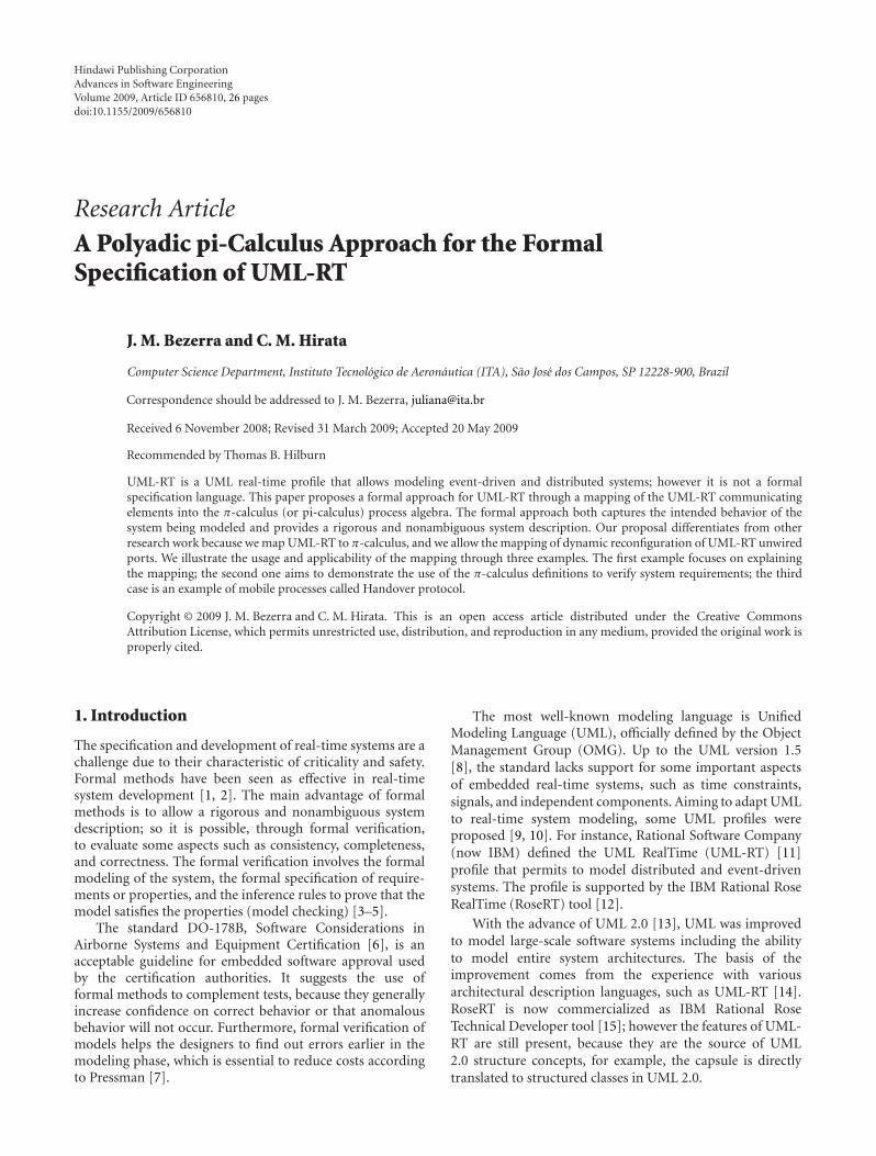
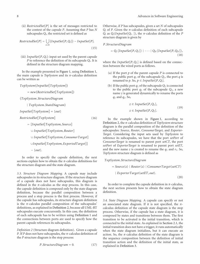
A capsule has a state diagram and a structure diagram. Astate diagram is similar to a UML standard state diagramand describes the capsule behavior. A structure diagramdetails the internal structure of a capsule, which includessubcapsules and their connections with each other. Figure 1shows the structure diagram of the capsule TopSystemthat comprises four subcapsules: source (instance of thecapsule Source), router (instance of the capsule Router),target1 (instance of the capsule ConsumerTarget), and target2(instance of the capsule ExporterTarget). The model wasconstructed using the RoseRT tool.
A port permits to exchange messages between capsules. Aprotocol needs to be specified for a port. A protocol definesboth the number of participants in the communication andthe signals that are received and sent by each participant. Theconnectors act as communicating channels between ports thatmust play different roles of the same protocol. A line betweentwo ports represents a connector. In Figure 1, the ports q andr implement the protocol named ConfigProtocol, and they areconnected to each other. The ports play conjugated roles,which can be noted in their representations: q as an empty(blank) square and r as a filled (black) square.
A port can be classified in terms of visibility (publicand protected), termination (end and relay), and connectivity(wired and unwired). A public port is located at the capsuleborder and can interact with other capsule ports. A protectedport is not visible from the outside; it serves as thecommunication point of the capsule with its subcapsules.In Figure 1, the capsule System has the public port out(indicated by the symbol +), and the protected ports setCTand setET (indicated by the symbol #).
With respect to the termination, an end port providesthe access to the capsule behavior given by its state diagram.In Figure 1, setCT and setET are end ports of the capsuleTopSystem. A relay port is used to export the subcapsuleinterfaces. When a relay port of a parent capsule receivesa message, the message is passed automatically to theconnected subcapsule port. And when a subcapsule sends amessage through a port connected to a relay port of its parentcapsule, the message is directly sent to the outside of theparent capsule. By definition, a relay port is public and wired.In Figure 1, out is a relay port of the capsule TopSystem.
A wired port (e.g., q and r in Figure 1) has a connectorjoining them to exchange messages. An unwired port doesnot have a connector with other ports, but it allowsdynamic communication during runtime through its nameregistration. In Figure 1, alert, s, and t are examples ofunwired ports. Unwired ports can be registered to receiveand send signals. For instance, the port s can be registeredwith the subscriber name x, and t can be registered with thesubscriber name y. In this case, if the port alert is configuredwith the provider name x, the signal sent by Router along alertis received by ConsumerTarget. Similarly, if the port alert isset to y, its signal is received by ExporterTarget. In RoseRT,the subscriber port is called Service Access Point (SAP) andthe provider port is called Service Provisioning Point (SPP).
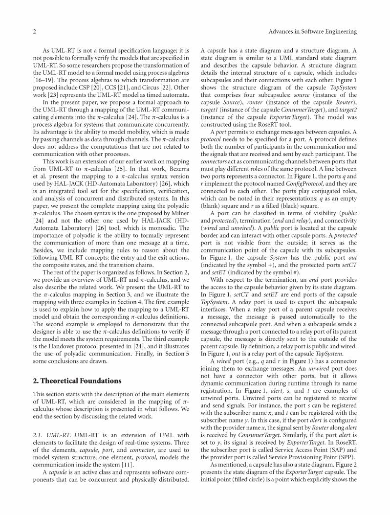
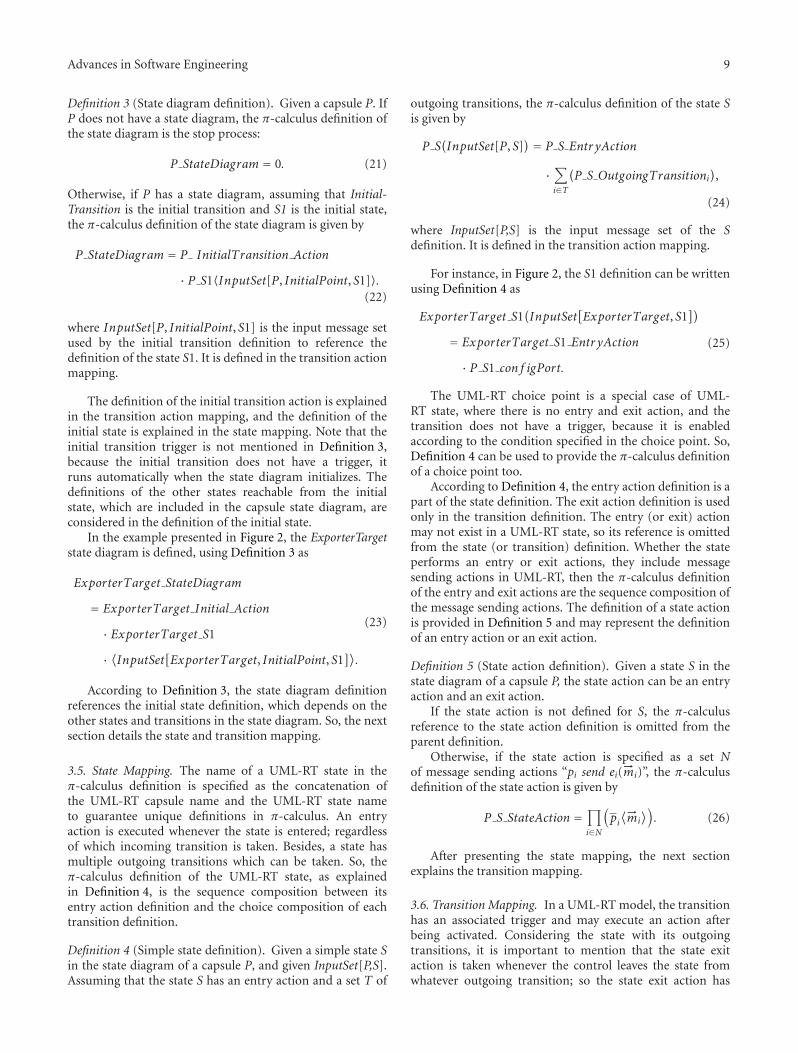
As mentioned, a capsule has also a state diagram. Figure 2presents the state diagram of the ExporterTarget capsule. Theinitial point (filled circle) is a point which explicitly shows the
Advances in Software Engineering 3
+/out : SingleCommProtocol~
/source: Source
+/q : ConfigProtocol~
/router: Router+/r
: ConfigProtocol
/target1: ConsumerTarget+/s : CommProtocol
+/setPort : ConfigProtocol
/target2: ExporterTarget
+/t : CommProtocol
+/setPort : ConfigProtocol
+/export : SingleCommProtocol~
#/setCT : ConfigProtocol~
#/setET: ConfigProtocol~
+/alerton∼
Figure 1: The structure diagram of the capsule TopSystem.
S3S2S1 msgConsumed
msgExported
InitialconfigPort
waitMsg
Figure 2: The state diagram of the capsule ExporterTarget.
beginning of the state machine. The initial transition, namedInitial, connects the initial point to the initial state. It doesnot have an associated trigger; however it may execute anassociated action.
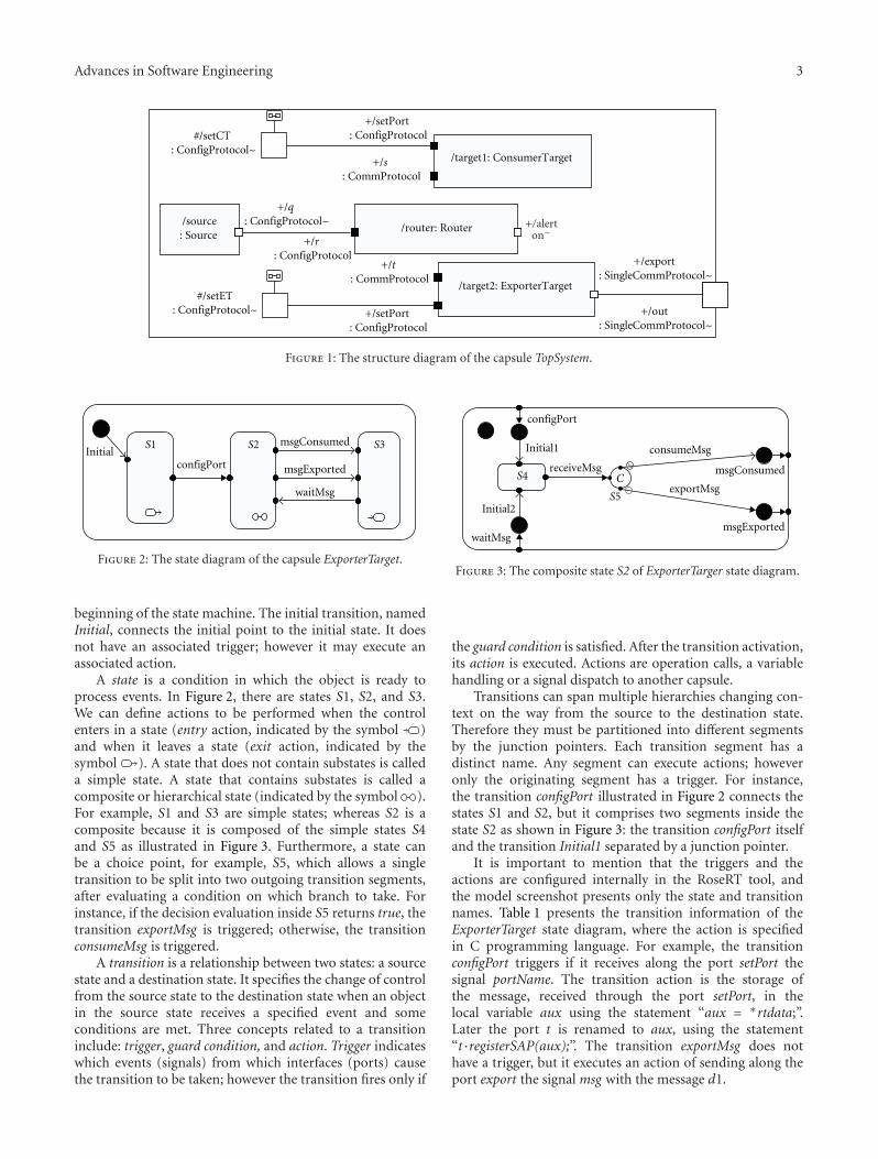
A state is a condition in which the object is ready toprocess events. In Figure 2, there are states S1, S2, and S3.We can define actions to be performed when the controlenters in a state (entry action, indicated by the symbol )and when it leaves a state (exit action, indicated by thesymbol ). A state that does not contain substates is calleda simple state. A state that contains substates is called acomposite or hierarchical state (indicated by the symbol ).For example, S1 and S3 are simple states; whereas S2 is acomposite because it is composed of the simple states S4and S5 as illustrated in Figure 3. Furthermore, a state canbe a choice point, for example, S5, which allows a singletransition to be split into two outgoing transition segments,after evaluating a condition on which branch to take. Forinstance, if the decision evaluation inside S5 returns true, thetransition exportMsg is triggered; otherwise, the transitionconsumeMsg is triggered.
A transition is a relationship between two states: a sourcestate and a destination state. It specifies the change of controlfrom the source state to the destination state when an objectin the source state receives a specified event and someconditions are met. Three concepts related to a transitioninclude: trigger, guard condition, and action. Trigger indicateswhich events (signals) from which interfaces (ports) causethe transition to be taken; however the transition fires only if
S4
configPort
msgConsumed
msgExportedwaitMsg
S5Initial2
Initial1 consumeMsg
exportMsg
receiveMsgC
Figure 3: The composite state S2 of ExporterTarger state diagram.
the guard condition is satisfied. After the transition activation,its action is executed. Actions are operation calls, a variablehandling or a signal dispatch to another capsule.
Transitions can span multiple hierarchies changing con-text on the way from the source to the destination state.Therefore they must be partitioned into different segmentsby the junction pointers. Each transition segment has adistinct name. Any segment can execute actions; howeveronly the originating segment has a trigger. For instance,the transition configPort illustrated in Figure 2 connects thestates S1 and S2, but it comprises two segments inside thestate S2 as shown in Figure 3: the transition configPort itselfand the transition Initial1 separated by a junction pointer.
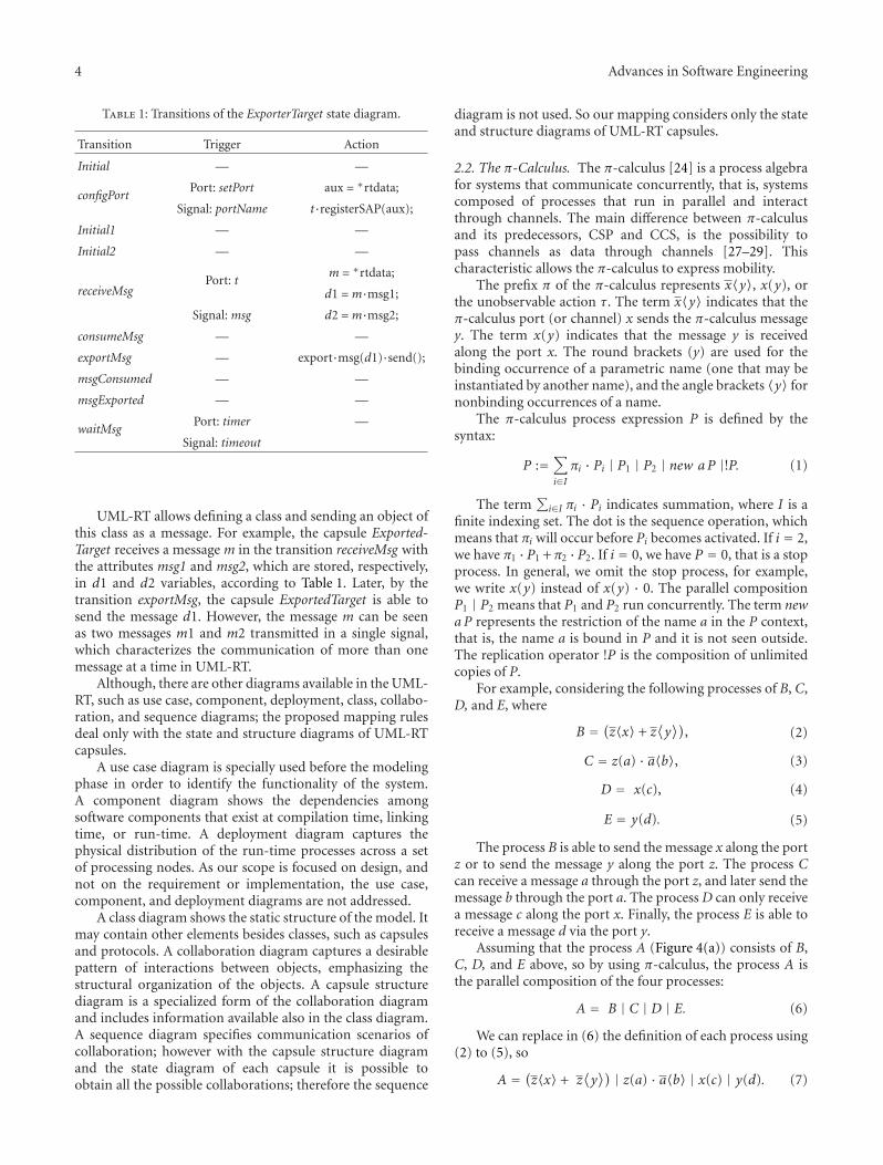
It is important to mention that the triggers and theactions are configured internally in the RoseRT tool, andthe model screenshot presents only the state and transitionnames. Table 1 presents the transition information of theExporterTarget state diagram, where the action is specifiedin C programming language. For example, the transitionconfigPort triggers if it receives along the port setPort thesignal portName. The transition action is the storage ofthe message, received through the port setPort, in thelocal variable aux using the statement “aux = ∗rtdata;”.Later the port t is renamed to aux, using the statement“t·registerSAP(aux);”. The transition exportMsg does nothave a trigger, but it executes an action of sending along theport export the signal msg with the message d1.
4 Advances in Software Engineering
Table 1: Transitions of the ExporterTarget state diagram.
Transition Trigger Action
Initial — —
configPortPort: setPort aux = ∗rtdata;
Signal: portName t·registerSAP(aux);
Initial1 — —
Initial2 — —
receiveMsgPort: t
m = ∗rtdata;
d1 =m·msg1;
Signal: msg d2 =m·msg2;
consumeMsg — —
exportMsg — export·msg(d1)·send();
msgConsumed — —
msgExported — —
waitMsgPort: timer —
Signal: timeout
UML-RT allows defining a class and sending an object ofthis class as a message. For example, the capsule Exported-Target receives a message m in the transition receiveMsg withthe attributes msg1 and msg2, which are stored, respectively,in d1 and d2 variables, according to Table 1. Later, by thetransition exportMsg, the capsule ExportedTarget is able tosend the message d1. However, the message m can be seenas two messages m1 and m2 transmitted in a single signal,which characterizes the communication of more than onemessage at a time in UML-RT.
Although, there are other diagrams available in the UML-RT, such as use case, component, deployment, class, collabo-ration, and sequence diagrams; the proposed mapping rulesdeal only with the state and structure diagrams of UML-RTcapsules.
A use case diagram is specially used before the modelingphase in order to identify the functionality of the system.A component diagram shows the dependencies amongsoftware components that exist at compilation time, linkingtime, or run-time. A deployment diagram captures thephysical distribution of the run-time processes across a setof processing nodes. As our scope is focused on design, andnot on the requirement or implementation, the use case,component, and deployment diagrams are not addressed.
A class diagram shows the static structure of the model. Itmay contain other elements besides classes, such as capsulesand protocols. A collaboration diagram captures a desirablepattern of interactions between objects, emphasizing thestructural organization of the objects. A capsule structurediagram is a specialized form of the collaboration diagramand includes information available also in the class diagram.A sequence diagram specifies communication scenarios ofcollaboration; however with the capsule structure diagramand the state diagram of each capsule it is possible toobtain all the possible collaborations; therefore the sequence
diagram is not used. So our mapping considers only the stateand structure diagrams of UML-RT capsules.
2.2. The π-Calculus. The π-calculus [24] is a process algebrafor systems that communicate concurrently, that is, systemscomposed of processes that run in parallel and interactthrough channels. The main difference between π-calculusand its predecessors, CSP and CCS, is the possibility topass channels as data through channels [27–29]. Thischaracteristic allows the π-calculus to express mobility.
The prefix π of the π-calculus represents x〈y〉, x(y), orthe unobservable action τ. The term x〈y〉 indicates that theπ-calculus port (or channel) x sends the π-calculus messagey. The term x(y) indicates that the message y is receivedalong the port x. The round brackets (y) are used for thebinding occurrence of a parametric name (one that may beinstantiated by another name), and the angle brackets 〈y〉 fornonbinding occurrences of a name.
The π-calculus process expression P is defined by thesyntax:
P :=∑
i∈Iπi · Pi | P1 | P2 | new aP |!P. (1)
The term∑
i∈I πi · Pi indicates summation, where I is afinite indexing set. The dot is the sequence operation, whichmeans that πi will occur before Pi becomes activated. If i = 2,we have π1 ·P1 +π2 ·P2. If i = 0, we have P = 0, that is a stopprocess. In general, we omit the stop process, for example,we write x(y) instead of x(y) · 0. The parallel compositionP1 | P2 means that P1 and P2 run concurrently. The term newa P represents the restriction of the name a in the P context,that is, the name a is bound in P and it is not seen outside.The replication operator !P is the composition of unlimitedcopies of P.
For example, considering the following processes of B, C,D, and E, where
B = (z〈x〉 + z⟨y⟩)
, (2)
C = z(a) · a〈b〉, (3)
D = x(c), (4)
E = y(d). (5)
The process B is able to send the message x along the portz or to send the message y along the port z. The process Ccan receive a message a through the port z, and later send themessage b through the port a. The process D can only receivea message c along the port x. Finally, the process E is able toreceive a message d via the port y.
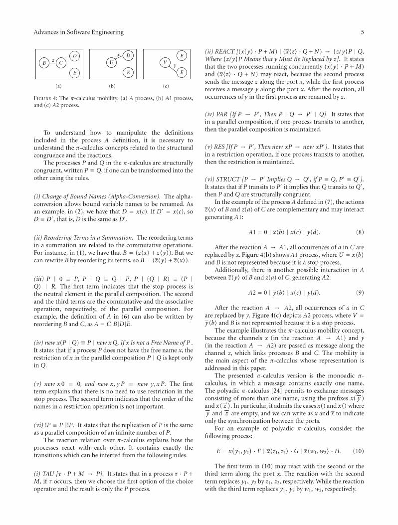
Assuming that the process A (Figure 4(a)) consists of B,C, D, and E above, so by using π-calculus, the process A isthe parallel composition of the four processes:
A = B | C | D | E. (6)
We can replace in (6) the definition of each process using(2) to (5), so
A = (z〈x〉 + z⟨y⟩) | z(a) · a〈b〉 | x(c) | y(d). (7)
Advances in Software Engineering 5
D
B Cz
E
(a)
Dx
U
E
(b)
EV
E
y
(c)
Figure 4: The π-calculus mobility. (a) A process, (b) A1 process,and (c) A2 process.
To understand how to manipulate the definitionsincluded in the process A definition, it is necessary tounderstand the π-calculus concepts related to the structuralcongruence and the reactions.
The processes P and Q in the π-calculus are structurallycongruent, written P ≡ Q, if one can be transformed into theother using the rules.
(i) Change of Bound Names (Alpha-Conversion). The alpha-conversion allows bound variable names to be renamed. Asan example, in (2), we have that D = x(c). If D′ = x(c), soD ≡ D′, that is, D is the same as D′.
(ii) Reordering Terms in a Summation. The reordering termsin a summation are related to the commutative operations.For instance, in (1), we have that B = (z〈x〉 + z〈y〉). But wecan rewrite B by reordering its terms, so B = (z〈y〉 + z〈x〉).
(iii) P | 0 ≡ P, P | Q ≡ Q | P, P | (Q | R) ≡ (P |Q) | R. The first term indicates that the stop process isthe neutral element in the parallel composition. The secondand the third terms are the commutative and the associativeoperation, respectively, of the parallel composition. Forexample, the definition of A in (6) can also be written byreordering B and C, as A = C|B|D|E.
(iv) new x(P | Q) ≡ P | new xQ, If x Is not a Free Name of P .It states that if a process P does not have the free name x, therestriction of x in the parallel composition P | Q is kept onlyin Q.
(v) new x 0 ≡ 0, and new x, y P ≡ new y, x P. The firstterm explains that there is no need to use restriction in thestop process. The second term indicates that the order of thenames in a restriction operation is not important.
(vi) !P ≡ P |!P. It states that the replication of P is the sameas a parallel composition of an infinite number of P.
The reaction relation over π-calculus explains how theprocesses react with each other. It contains exactly thetransitions which can be inferred from the following rules.
(i) TAU [τ · P + M → P]. It states that in a process τ · P +M, if τ occurs, then we choose the first option of the choiceoperator and the result is only the P process.
(ii) REACT [(x(y) · P +M) | (x〈z〉 ·Q +N) → {z/y}P | Q,Where {z/y}P Means that y Must Be Replaced by z]. It statesthat the two processes running concurrently (x(y) · P + M)and (x〈z〉 · Q + N) may react, because the second processsends the message z along the port x, while the first processreceives a message y along the port x. After the reaction, alloccurrences of y in the first process are renamed by z.
(iv) PAR [If P → P′, Then P | Q → P′ | Q]. It states thatin a parallel composition, if one process transits to another,then the parallel composition is maintained.
(v) RES [If P → P′, Then new xP → new xP′]. It states thatin a restriction operation, if one process transits to another,then the restriction is maintained.
(vi) STRUCT [P → P′ Implies Q → Q′, if P ≡ Q, P′ ≡ Q′].It states that if P transits to P′ it implies that Q transits to Q′,then P and Q are structurally congruent.
In the example of the process A defined in (7), the actionsz〈x〉 of B and z(a) of C are complementary and may interactgenerating A1:
A1 = 0 | x〈b〉 | x(c) | y(d). (8)
After the reaction A → A1, all occurrences of a in C arereplaced by x. Figure 4(b) shows A1 process, whereU = x〈b〉and B is not represented because it is a stop process.
Additionally, there is another possible interaction in Abetween z〈y〉 of B and z(a) of C, generating A2:
A2 = 0 | y〈b〉 | x(c) | y(d). (9)
After the reaction A → A2, all occurrences of a in Care replaced by y. Figure 4(c) depicts A2 process, where V =y〈b〉 and B is not represented because it is a stop process.
The example illustrates the π-calculus mobility concept,because the channels x (in the reaction A → A1) and y(in the reaction A → A2) are passed as message along thechannel z, which links processes B and C. The mobility isthe main aspect of the π-calculus whose representation isaddressed in this paper.
The presented π-calculus version is the monoadic π-calculus, in which a message contains exactly one name.The polyadic π-calculus [24] permits to exchange messagesconsisting of more than one name, using the prefixes x(−→y )and x〈−→z 〉. In particular, it admits the cases x() and x〈〉where−→y and −→z are empty, and we can write as x and x to indicateonly the synchronization between the ports.
For an example of polyadic π-calculus, consider thefollowing process:
E = x(y1, y2
) · F | x〈z1, z2〉 ·G | x〈w1,w2〉 ·H. (10)
The first term in (10) may react with the second or thethird term along the port x. The reaction with the secondterm replaces y1, y2 by z1, z2, respectively. While the reactionwith the third term replaces y1, y2 by w1, w2, respectively.
6 Advances in Software Engineering
The definition of E is different from E′ written inmonoadic π-calculus, as follows:
E′ = x(y1) · x(y2
) · F | x〈z1〉 · x〈z2〉 ·G | x〈w1〉 · x〈w2〉H.(11)
In (11), the first term may react with the second and laterwith the third term, resulting that y1 is replaced by z1, and y2
by w2. It is also possible that the first term may react with thethird and later with the second term. In both cases, the resultof (11) using monoadic π-calculus is different from that oneexpected in (10) using polyadic π-calculus. For the correctencoding of the polyadic using monoadic, it is necessary toguarantee that there can be no interference on the channelalong which a composite message is sent. It is addressed byMilner in [24].
A process in monoadic or polyadic π-calculus can alsohave a list of input names written between round brackets,for example,
I(m,n) = m〈n〉 · I′. (12)
In this case, the definition of process I has the port namem and the message n available as input parameters. If aprocess J uses the definition of I, then J calls I definitionpassing the input names between angle brackets, for example,
J(p) = p
(q) · I⟨q, r
⟩. (13)
In (13), J references I definition passing q and r to,respectively, rename I inputs m and n.
So in π-calculus, the round brackets () are used to bothorganize the input set of processes and organize the setof messages received through a port. Whereas the anglebrackets 〈〉 are used to organize both the input set of processreferences and the set of messages sent through a port.
As described above, the π-calculus is a process algebrato describe and analyze concurrent systems consisting ofprocesses (or agents) which interact with other connectedprocesses.
2.3. Related Work. Some approaches use Z [30] and Object-Z [31] to formalize UML models. Miao et al. [32] deal withthe UML class, sequence, and statechart diagrams; whileKim and Carrington [33] present a formal Object-Z modelof the UML state machine. However, they consider UMLand not UML-RT with its architectural components. Thatis because Z and Object-Z are suitable for capturing dataand states, and not for capturing dynamic communicationconfigurations. On the other hand, π-calculus is suitableto support dynamic communication, that is the focus ofour UML-RT formalization proposal. Due to the π-calculuscontribution, other formalisms propose the combination ofa state-based formalism and a dynamic action-based calculusby integrating the mobility concepts of the π-calculus to Zand Object-Z [34–36].
Terriza et al. [16] describe a mapping of UML-RT to CSP+ T, whose objective is to provide time elements to UML-RT,
making the mapping of the capsule state diagram and theclass diagram to CSP + T definitions. CSP + T is a formalspecification language that adds time interval description toCSP. Fischer et al. [17] propose the conversion of UML-RT structure diagram to CSP process algebra. Engels et al.[18] describe a translation from the UML-RT capsule stateand structure diagrams to CSP. Ramos et al. [19] propose amapping of UML-RT state, structure, and class diagrams toCircus, which is a formal method that combines concepts ofCSP and Z [30].
The aforementioned related work deals with syn-chronous methods. In general, the information in thestructure diagram is also provided in the class diagram, andthen some authors use one or another. The capsule definitionreuse is a criterion that indicates whether the generateddefinitions in the process algebra can reuse the definition ofthe capsules. For example, assuming that the capsule A hastwo subcapsules of type B, the definition of A in π-calculusreferences twice the B definition, but for each one, A setsdifferent names as input due to the π-calculus mobility. InCSP and CCS, it would be necessary to write two equationsof B, one for each configuration that B may have. An exampleof this in CSP is the traffic light system in [17].
Knapp et al. [23] compile UML-RT state diagraminto timed automata and represent the timed-annotatedUML collaborations as another timed automaton, using aprototype called HUGO/RT. Afterwards, the prototype callsthe model checker UPPAAL to verify the model againstthe scenario specified by the UML collaboration. Someinteresting characteristics include the representation of timeconsidered in a UML-RT timeout and the mapping of theevent queue that holds the events not already handled bythe machine. However, there are two limitations of thisapproach. First, the events cannot transmit messages; second,the composite and the choice states are not represented.
Additionally, all the above related work considers only thewired ports in their mappings; that is, they do not map theUML-RT unwired ports, so mobility is not addressed.
In our previous work, we propose the UML-RT to π-calculus mapping rules using the π-calculus syntax versionaccepted by the HAL-JACK tool. The HAL-JACK syntax usesthe monoadic π-calculus, which lead us to represent only thecommunication of one message at a time. Besides, the HAL-JACK syntax requires that all names used in a definition mustbe declared in its input list; this restriction causes complexmapping rules. In our proposal, we use the π-calculus syntaxproposed by Milner and we represent the communication ofmore than one message through polyadic π-caculus. Othercontribution comprises the mapping of the entry and the exitactions, the composite states, and the transition chains.
3. The UML-RT to Polyadic π-Calculus Mapping
In this section, we propose the mapping from the UML-RT to the π-calculus. We make some initial considerationsregarding the mapping, and later we explain the mappingsof the following elements of UML-RT: capsule, structurediagram, state diagram, state, and transition.
Advances in Software Engineering 7
3.1. Initial Considerations. The processing of a single eventat a time by a state machine is known as a run-to-completion (RTC) step, which means that a transitioncannot be interrupted by the arrival of an event. When thetransition is partitioned into different segments, in the caseof the composite states, only the originating segment has atrigger defined, so there is only one event to be processed.So, even in this case, the transition chain (i.e., the sumof all transition segments) is executed in one RTC step.The communication model used by the π-calculus is thesynchronized communication, which is suitable to the RTCstep, because the object corresponding to the sender statediagram blocks until it receives the notification about thereceipt of the event at the object corresponding to the receiverstate diagram.
The polyadic π-calculus definitions resulted from themapping follow the syntax proposed by Milner [24]. TheUML-RT capsule state diagrams are used in the mappingto retrieve the behavior of the capsules, while the structurediagrams are used to retrieve the association betweencapsules. The base of the mapping is that a UML-RT portis represented by a π-calculus port; whereas the messagestransmitted through the signal are represented by the π-calculus messages. In order to be able to represent thetransmission of zero or more messages, our approach usesthe polyadic π-calculus.
UML-RT offers a limited support for time annotations,there is one element to set a timer and simulate a timeout.In the RoseRT tool, this timer is allowed through a port thatimplements a built-in Timing protocol. In our mapping, thetimeout is represented by the unobservable action τ, becauseit is a private interaction inside the capsule.
The main elements of a transition are trigger, action, andguard condition. However, as the focus of the UML-RT toπ-calculus mapping is on communication elements, guardcondition is not considered. The transition is triggered by thereceipt of a message. The considered transition actions are amessage sending or a name reconfiguration, where a namereconfiguration is a way to reconfigure the unwired ports. Weassume that the entry and exit actions are only the messagesending statements.
The RoseRT tool allows the use of three programminglanguages, C, C++, and Java, to specify the transition and thestate actions. Aiming to be independent from programminglanguages and simplify the notation used in the mappingrules, we propose the following pseudo codes.
(i) The message receipt statement is written as“p receive e(−→m)”, which means that the port preceives the signal e with the list −→m of messages.
(ii) The message sending statement is represented as“p send e(−→m)”, that is, the port p sends the signal ewith the list −→m of messages.
(iii) The name reconfiguration statement is written as“name1 = name2”, that is, name1 is from now onused with the value of name2. In the RoseRT, thisinformation is given through the commands SAP orSPP, for example, “name1·registerSAP(name2)”.
It is important to recall that the list −→m of messages can beempty, when there exists only the synchronization betweenthe ports and no message is transmitted.
Some notations used in the mapping rules need to bepresented.
(i) The term P(L) represents the π-calculus definition ofP with its input set L.
(ii) The term P〈L〉 represents a reference to the π-calculus definition of P. The input set L is passed tothe P definition. This notation is used in the syntaxproposed by Milner and is commented in Section 2.2.
(iii) The term P represents the π-calculus definition ofa component without a defined input set. Eachπ-calculus reference to this component should bereplaced by the definition P.
(iv) The result of L1 − L2 is L1 without the elementscontained in L2, where L1 and L2 are sets.
(v) The symbol⋃
is the union operator in sets. So,⋃i∈N Li = L1 ∪ L2 ∪ · · · ∪ LN .
(vi) The symbol∑
indicates the application of the choiceoperator in π-calculus processes. So,
∑i∈N Pi = P1 +
P2 + · · · + PN .
(vii) The symbol∏
indicates the application of thesequence operator in π-calculus actions. So,∏
i∈Nπi = π1 · π2 · · ·πN .
The result of UML-RT mapping is the π-calculusdefinition of the main capsule in UML-RT model. Afterintroducing the essence of the mapping and the notations,we are able to present the capsule mapping.
3.2. Capsule Mapping. Each UML-RT capsule has its ownstate diagram and may contain other capsules in its structurediagram. So, the capsule definition in the π-calculus iscomposed by two parts: the structure diagram definition inthe π-calculus and the state diagram definition in the π-calculus. These two definitions are arranged with the parallelcomposition operator of the π-calculus, as presented inDefinition 1, because the behavior of the capsule and itssubcapsules are executed concurrently in UML-RT.
Definition 1 (Capsule definition). Given a capsule P, its π-calculus definition is the parallel composition of its statediagram definition and its structure diagram definition. So,the π-calculus definition of the capsule P is given by
P(InputSet[P]
)
= new(RestrictedSet[P])
· (P StructureDiagram | P StateDiagram),
(14)
where
(i) InputSet[P] is the input message set of the P capsuledefinition. It is defined as the set of the public wiredports of the capsule P.
8 Advances in Software Engineering
(ii) RestrictedSet[P] is the set of messages restricted tothe context of the capsule P. Assuming that P has Nsubcapsules Qi, the restricted set is defined as
RestrictedSet[P] =⋃
i∈N
(InputSet[P,Qi]
)− InputSet[P].
(15)
(iii) InputSet[P,Qi]: input set used by the parent capsuleP to reference the definition of its subcapsule Qi. It isdefined in the structure diagram mapping.
In the example presented in Figure 1, using Definition 1,the main capsule is TopSystem and its π-calculus definitioncan be written as
TopSystem(InputSet
[TopSystem
])
= new(RestrictedSet
[TopSystem
])
(TopSystem StructureDiagram
| TopSystem StateDiagram)
InputSet[TopSystem
] = {out}RestrictedSet
[TopSystem
]
= {InputSet[TopSystem, Source]
∪ InputSet[TopSystem,Router]
∪ InputSet[TopSystem,ConsumerTarget]
∪InputSet[TopSystem,ExportedTarget]}
− {out}.
(16)
In order to specify the capsule definition, the nextsections explain how to obtain the π-calculus definitions forthe structure diagram and the state diagram.
3.3. Structure Diagram Mapping. A capsule may includesubcapsules in its structure diagram. If the structure diagramof a capsule does not have subcapsules, this diagram isdefined in the π-calculus as the stop process. In this case,the capsule definition is composed only by the state diagramdefinition, because the parallel composition between aprocess and a stop process is the first process. However, ifthe capsule has subcapsules, its structure diagram definitionis the π-calculus parallel composition of the subcapsules’definitions, as explained in Definition 2, because all UML-RTsubcapsules execute concurrently. In this case, the definitionof each subcapsule has to be written using Definition 1 andthe connections between ports are used to specify how theparent capsule references its subcapsules.
Definition 2 (Structure diagram definition). Given a capsuleP. If P does not have subcapsules, the π-calculus definition ofthe P structure diagram is the stop process:
P StructureDiagram = 0. (17)
Otherwise, if P has subcapsules, given a set N of subcapsulesQi of P. Given the π-calculus definition of each subcapsuleQi as Qi(InputSet[Qi. ]), the π-calculus definition of the Pstructure diagram is given by
P StructureDiagram
= Q1⟨InputSet[P,Q1]
⟩ | · · · | QN⟨InputSet[P,QN ]
⟩,
(18)
where the InputSet[P,Q1] is defined based on the connec-tion between the wired ports as follows.
(a) If the port p of the parent capsule P is connected tothe public port q1 of the subcapsule Q1, the port q isrenamed to p. So, p ∈ InputSet[P,Qi].
(b) If the public port q1 of the subcapsuleQ1 is connectedto the public port q2 of the subcapsule Q2, a newname z is generated dynamically to rename the portsq1 and q2. So,
z ∈ InputSet[P,Q1],
z ∈ InputSet[P,Q2].(19)
In the example shown in Figure 1, according toDefinition 2, the π-calculus definition of TopSystem structurediagram is the parallel composition of the definition of thesubcapsules: Source, Router, ConsumerTarget, and Exporter-Target. Considering the input sets used by TopSystem toreference its subcapsules, we have that the port setPort ofConsumerTarget is renamed to parent port setCT, the portsetPort of ExporterTarget is renamed to parent port setET,and the new name z is created to rename the q1 and r1. So,TopSystem structure diagram is defined as
TopSystem StructureDiagram
= Source〈z〉 | Router〈z〉 | ConsumerTarget〈setCT〉| ExporterTarget〈setET , out〉.
(20)
In order to complete the capsule definition in π-calculus,the next section presents how to obtain the state diagramdefinition.
3.4. State Diagram Mapping. A capsule can specify or notan associated state diagram. If it is not specified, the π-calculus definition of the capsule state diagram is the stopprocess. Otherwise, if the capsule has a state diagram, it iscomposed by states and transitions between them. The firsttransition to be activated is the initial transition, which isconnected to the initial state. As explained in Section 2.1, theinitial transition does not have a trigger, it runs automaticallywhen the state diagram initializes, but it can execute anaction. So, the π-calculus definition of the state diagram isthe sequence composition between the definition of initialtransition action and the definition of the initial state, asexplained in Definition 3.
Advances in Software Engineering 9
Definition 3 (State diagram definition). Given a capsule P. IfP does not have a state diagram, the π-calculus definition ofthe state diagram is the stop process:
P StateDiagram = 0. (21)
Otherwise, if P has a state diagram, assuming that Initial-Transition is the initial transition and S1 is the initial state,the π-calculus definition of the state diagram is given by
P StateDiagram = P InitialTransition Action
· P S1〈InputSet[P, InitialPoint, S1]〉.(22)
where InputSet[P, InitialPoint, S1] is the input message setused by the initial transition definition to reference thedefinition of the state S1. It is defined in the transition actionmapping.
The definition of the initial transition action is explainedin the transition action mapping, and the definition of theinitial state is explained in the state mapping. Note that theinitial transition trigger is not mentioned in Definition 3,because the initial transition does not have a trigger, itruns automatically when the state diagram initializes. Thedefinitions of the other states reachable from the initialstate, which are included in the capsule state diagram, areconsidered in the definition of the initial state.
In the example presented in Figure 2, the ExporterTargetstate diagram is defined, using Definition 3 as
ExporterTarget StateDiagram
= ExporterTarget Initial Action
· ExporterTarget S1
· ⟨InputSet[ExporterTarget, InitialPoint, S1]⟩.
(23)
According to Definition 3, the state diagram definitionreferences the initial state definition, which depends on theother states and transitions in the state diagram. So, the nextsection details the state and transition mapping.
3.5. State Mapping. The name of a UML-RT state in theπ-calculus definition is specified as the concatenation ofthe UML-RT capsule name and the UML-RT state nameto guarantee unique definitions in π-calculus. An entryaction is executed whenever the state is entered; regardlessof which incoming transition is taken. Besides, a state hasmultiple outgoing transitions which can be taken. So, theπ-calculus definition of the UML-RT state, as explainedin Definition 4, is the sequence composition between itsentry action definition and the choice composition of eachtransition definition.
Definition 4 (Simple state definition). Given a simple state Sin the state diagram of a capsule P, and given InputSet[P,S].Assuming that the state S has an entry action and a set T of
outgoing transitions, the π-calculus definition of the state Sis given by
P S(InputSet[P, S]
) = P S Entr yAction
·∑
i∈T
(P S OutgoingTransitioni
),
(24)
where InputSet[P,S] is the input message set of the Sdefinition. It is defined in the transition action mapping.
For instance, in Figure 2, the S1 definition can be writtenusing Definition 4 as
ExporterTarget S1(InputSet
[ExporterTarget, S1
])
= ExporterTarget S1 Entr yAction
· P S1 con f igPort.
(25)
The UML-RT choice point is a special case of UML-RT state, where there is no entry and exit action, and thetransition does not have a trigger, because it is enabledaccording to the condition specified in the choice point. So,Definition 4 can be used to provide the π-calculus definitionof a choice point too.
According to Definition 4, the entry action definition is apart of the state definition. The exit action definition is usedonly in the transition definition. The entry (or exit) actionmay not exist in a UML-RT state, so its reference is omittedfrom the state (or transition) definition. Whether the stateperforms an entry or exit actions, they include messagesending actions in UML-RT, then the π-calculus definitionof the entry and exit actions are the sequence composition ofthe message sending actions. The definition of a state actionis provided in Definition 5 and may represent the definitionof an entry action or an exit action.
Definition 5 (State action definition). Given a state S in thestate diagram of a capsule P, the state action can be an entryaction and an exit action.
If the state action is not defined for S, the π-calculusreference to the state action definition is omitted from theparent definition.
Otherwise, if the state action is specified as a set Nof message sending actions “pi send ei(
−→mi)”, the π-calculusdefinition of the state action is given by
P S StateAction =∏
i∈N
(pi⟨−→mi
⟩). (26)
After presenting the state mapping, the next sectionexplains the transition mapping.
3.6. Transition Mapping. In a UML-RT model, the transitionhas an associated trigger and may execute an action afterbeing activated. Considering the state with its outgoingtransitions, it is important to mention that the state exitaction is taken whenever the control leaves the state fromwhatever outgoing transition; so the state exit action has
10 Advances in Software Engineering
to be computed after the transition trigger and before thetransition action. Then, the outgoing transition definitionin the π-calculus, as detailed in Definition 6, is a sequencecomposition of the transition trigger definition, the state exitaction, the transition action definition, and the target statedefinition.
Definition 6 (Outgoing transition definition). Given thesimple states S1 and S2 in the state diagram of a capsule P.Given an outgoing transition from S1 to S2, the π-calculusdefinition of the transition is
P S1 OutgoingTransition
= P S1 OutgoingTransition Trigger
· P S1 ExitAction
· P S1 OutgoingTransition Action
· P S2⟨InputSet[P, S1, S2]
⟩,
(27)
where InputSet[P, S1, S2] is the input message set used by thestate S1 to reference the definition of the state S2. It is definedin the transition action mapping.
For instance, the transition receiveMsg can be defined,using Definition 6, as
ExporterTarget S4 receiveMsg
= ExporterTarget S4 receiveMsg Trigger
· ExporterTarget S4 ExitAction
· ExporterTarget S4 receiveMsg Action
· ExporterTarget S5⟨InputSet
[ExporterTarget, S4, S5
]⟩.
(28)
A special case of a UML-RT transition is when thetransition is a transition chain that transposes the boundariesof composite states. As it is explained in Section 2.1, thistransition is partitioned into different segments by thejunction pointers, and only the originating segment has atrigger defined, while all segments can execute actions. In thiscase, we have to compute in the right order the followingaspects: the trigger of the first segment, the actions of allsegments, the entry or the exit action of all the transposedparent states, as detailed in Definition 7.
Definition 7 (Definition of the outgoing transition chain).Given an outgoing transition chain from a state S1 to a stateS2, where S1 and S2 belong to the state diagram of a capsuleP. Assuming that the outgoing transition chain transposesthe boundary of a set N of the parent states CS1’s of S1, andlater transposes the boundary of a set M of the parent statesCS2’s of S2, where N or M can be empty sets, the transition
chain is composed byN +M+1 segments. In this case, the π-calculus definition of the outgoing transition chain is givenby
P S1 OutgoingTransitionChain
= P S1 Segment1 Trigger
· P S1 ExitAction
· P S1 Segment1 Action
· (P S1 OutgoingTransitionChain Up
·P S1 OutgoingTransitionChain Down)
· P S2⟨InputSet[P, S, S2]
⟩,
(29)
where
P S1 OutgoingTransitionChain Up
=∏
i∈N
(P CS1i ExitAction · P S1 Segmenti+1 Action
)
P S1 OutgoingTransitionChain Down
=∏
j∈M
(P CS2 j Entr yAction
·P S1 Segmentj+1+N Action).
(30)
The ExporterTarget state diagram, illustrated in Figures 2and 3, has the transition chain initiating with the segmentconsumeMsg. This transition chain originates at the stateS5 and transposes the boundary of the composite state S2until reaching the state S3. According to Definition 7, thetransition chain consumeMsg is defined as
ExportedTarget S5 consumeMsg
= ExportedTarget S5 consumeMsg Trigger
· ExportedTarget S5 ExitAction
· ExportedTarget S5 consumeMsg Action
· ExportedTarget S2 ExitAction
· ExportedTarget S5 msgConsumed Action
· ExportedTarget S3〈InputSet[ExporterTarget, S5, S3]〉.
(31)
As commented in Section 3.1, the transition trigger isa message receipt statement and the transition action canbe a message sending statement or a name reconfigurationstatement. The transition trigger definition is providedin Definition 8, while the transition action definition isexplained in Definition 9.
Definition 8 (Transition trigger definition). Given a transi-tion from state S1 to state S2 in the state diagram of a capsuleP.
Advances in Software Engineering 11
If there is no trigger specified to the transition, theπ-calculus reference to the transition trigger definition isomitted from the parent definition.
Otherwise, assuming that the transition can be trig-gered by a set N of message receipt statements as“pi receive ei(
−→mi)”, the π-calculus definition of the transitiontrigger is given by
P S1 Transition Trigger =∑
i∈N
(pi(−→mi
)). (32)
A special case occurs when ei is a timeout signal. In this case,the trigger is represented by the unobservable action τ. So,pi(−→mi) = τ.
Analyzing Definition 8, the transition trigger definitionconsiders all the messages that the capsule can receive inthe current transition. However, it cannot be defined, forexample, in an outgoing transition of a choice point and inthe first segment of a transition chain.
In Definition 9, the transition action considers all themessage sending and the reconfiguration statements. In caseof a reconfiguration statement, it is important that the oldname is the one used by the next state, while the new name isused to reference the next state definition. The input messageset of the capsule definition is maintained in the other inputsets to keep the consistence of the π-calculus definitions.Note that Definition 9 holds to the actions of all segmentsin a transition chain.
Definition 9 (Transition action definition). Given a transi-tion from state S1 to state S2 in the state diagram of a capsuleP.
If there is no action associated to the transition, theπ-calculus reference to the transition action definition isomitted from the parent definition.
Otherwise, assuming that the transition action is com-posed of a set N of message sending statements as“pi send ei(
−→mi)” and also by a set M of name reconfigurationstatements as “yj = xj”, the π-calculus definition of thetransition action is given by
P S1 Transition Trigger =∏
i∈N
(pi〈−→mi〉
),
InputSet[P, S1, S2] =⋃
j∈Mxj ∪ InputSet[P],
InputSet[P, S2] =⋃
j∈Myj ∪ InputSet[P],
(33)
where InputSet[P] is the input message set of the P capsuledefinition, already defined in Definition 1.
For instance, the transition receiveMsg of the Exporter-Target state diagram, illustrated in Figure 3, has a triggerwhich can be defined using Definition 8 as follows:
ExporterTarget S4 receiveMsg Trigger = t(d1,d2). (34)
It is an example of receiving two messages in a singlesynchronization, which shows the importance of usingpolyadic π-calculus in the mapping.
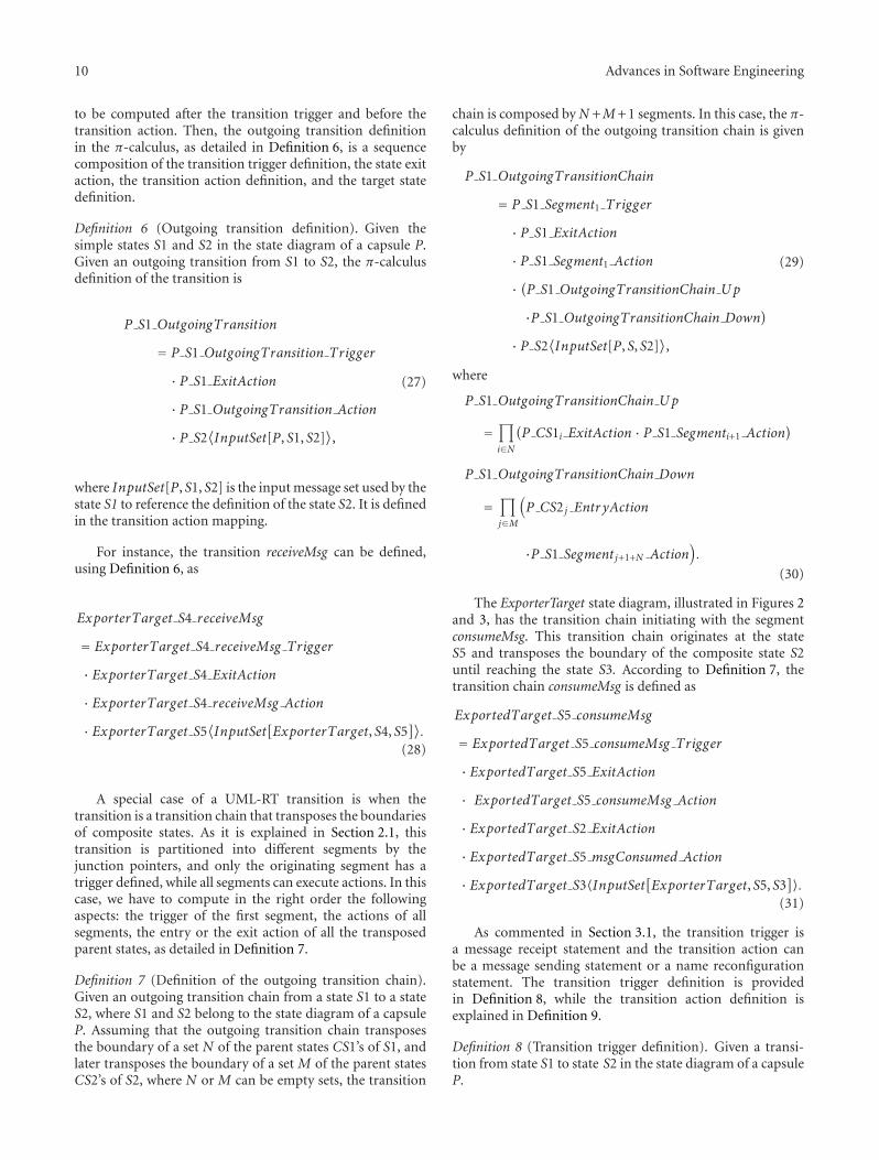
S1
Initial
Figure 5: The state diagram of the capsule TopSystem.
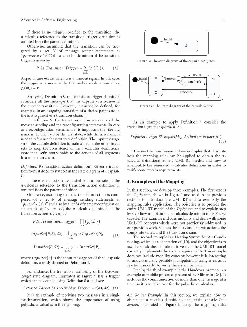
S1 S3S2
C
Timeout2
Initial TimeoutsendPortY
sendPortX
Figure 6: The state diagram of the capsule Source.
As an example to apply Definition 9, consider thetransition segment exportMsg. So,
ExporterTarget S5 exportMsg Action() = export〈d1〉.(35)
The next section presents three examples that illustratehow the mapping rules can be applied to obtain the π-calculus definitions from a UML-RT model, and how tomanipulate the generated π-calculus definitions in order toverify some system requirements.
4. Examples of the Mapping
In this section, we develop three examples. The first one isthe TopSystem, shown in Figure 1 and used in the previoussections to introduce the UML-RT and to exemplify themapping rules application. The objective is to provide theentire UML-RT model of the TopSystem and to explain stepby step how to obtain the π-calculus definition of its Sourcecapsule. The example includes mobility and deals with someUML-RT concepts which were not previously addressed inour previous work, such as the entry and the exit actions, thecomposite states, and the transition chains.
The second example is a Heating System for Air Condi-tioning, which is an adaptation of [10], and the objective is touse the π-calculus definitions to verify if the UML-RT modelcorrectly implements the system requirements. This exampledoes not include mobility concept; however it is interestingto understand the possible manipulations using π-calculusreactions in order to verify the system behavior.
Finally, the third example is the Handover protocol, anexample of mobile processes presented by Milner in [24]. Itincludes the communication of more than one message at atime, so it is suitable case for the polyadic π-calculus.
4.1. Router Example. In this section, we explain how toobtain the π-calculus definition of the entire capsule Top-System, illustrated in Figure 1, using the mapping rules
12 Advances in Software Engineering
Table 2: Entry and exit actions of the states in the capsuleTopSystem and its subcapsules.
Capsule State Entry action Exitaction
TopSystem S1 — —
Source
S1 timer·informIn(RTTimespec(10, 0)); —
S2 — —
S3 timer·informIn(RTTimespec(1, 0)); —
Router
S1 — —
S2 timer·informIn(RTTimespec(4, 0)); —
S3 timer·informIn(RTTimespec(1, 0)); —
ConsumerTarget
S1 — —
S2 — —
S3 timer·informIn(RTTimespec(2, 0)); —
ExporterTarget
S1 — —
S2 — —
S3 timer·informIn(RTTimespec(1, 0)); —
S4 — —
S5 — —
provided in Section 3. The capsule TopSystem comprises thefollowing capsules: source (instance of the capsule Source),router (instance of the capsule Router), target1 (instance ofthe capsule ConsumerTarget), and target2 (instance of thecapsule ExporterTarget). We provide the state diagram ofthe capsules TopSystem, Source, Router, and ConsumerTarget,respectively, in Figures 5, 6, 7, and 8.
The entry and exit actions of the states in the capsuleTopSystem and its subcapsules are detailed in Table 2. Itis important to note that these actions are not consideredas a sending message statement or a name reconfigurationstatement, because they just set up an internal timeout, sothe π-calculus definition of each action is the stop process.
The specification of the transitions inside the statediagrams of the capsule TopSystem and its subcapsules isprovided in Table 3. Table 4 presented the pseudocode thatrepresents the transition trigger and the transition action;the pseudocode helps to understand the application of themapping rules to obtain the π-calculus definitions.
The structure diagrams of the TopSystem subcapsules arenot provided because the majority of ports are public, sothey can be seen in TopSystem structure diagram (shownin Figure 1). The only exception is the protected port timerpresented in all TopSystem subcapsules. The port timerimplements the protocol Timing (a built-in protocol of theRoseRT tool) and receives the timeout signal.
In order to show how to apply the mapping rules toobtain the π-calculus definition of a UML-RT capsule, wedetail the mapping of the capsule Source.
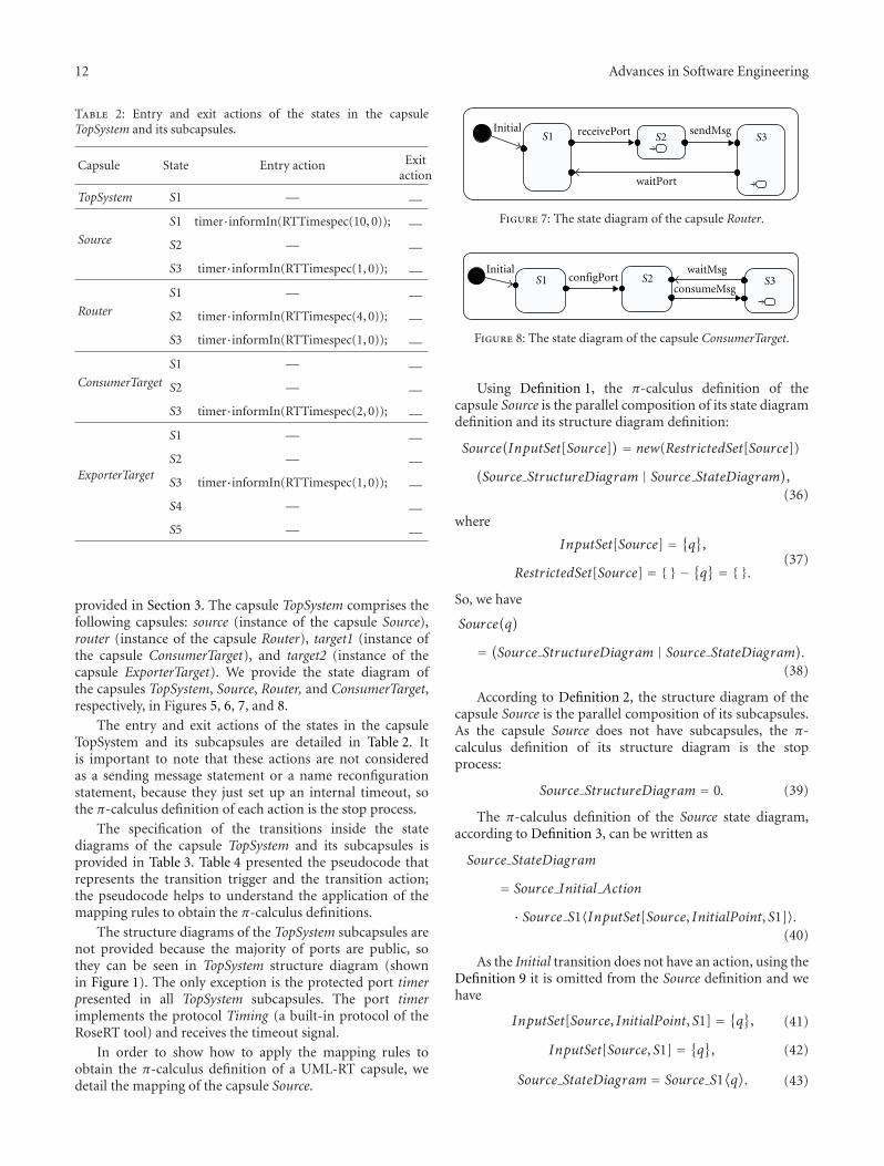
S1 S2 S3Initial
waitPort
receivePort sendMsg
Figure 7: The state diagram of the capsule Router.
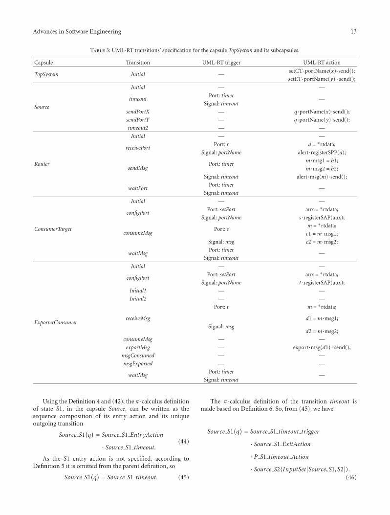
S2 S3S1Initial waitMsg
configPortconsumeMsg
Figure 8: The state diagram of the capsule ConsumerTarget.
Using Definition 1, the π-calculus definition of thecapsule Source is the parallel composition of its state diagramdefinition and its structure diagram definition:
Source(InputSet[Source]
) = new(RestrictedSet[Source])(Source StructureDiagram | Source StateDiagram),
(36)
where
InputSet[Source] = {q},
RestrictedSet[Source] = {} − {q} = {}.(37)
So, we have
Source(q)
= (Source StructureDiagram | Source StateDiagram).(38)
According to Definition 2, the structure diagram of thecapsule Source is the parallel composition of its subcapsules.As the capsule Source does not have subcapsules, the π-calculus definition of its structure diagram is the stopprocess:
Source StructureDiagram = 0. (39)
The π-calculus definition of the Source state diagram,according to Definition 3, can be written as
Source StateDiagram
= Source Initial Action
· Source S1〈InputSet[Source, InitialPoint, S1]〉.(40)
As the Initial transition does not have an action, using theDefinition 9 it is omitted from the Source definition and wehave
InputSet[Source, InitialPoint, S1] = {q}, (41)
InputSet[Source, S1] = {q}, (42)
Source StateDiagram = Source S1⟨q⟩. (43)
Advances in Software Engineering 13
Table 3: UML-RT transitions’ specification for the capsule TopSystem and its subcapsules.
Capsule Transition UML-RT trigger UML-RT action
TopSystem Initial —setCT·portName(x)·send();
setET·portName(y) ·send();
Source
Initial — —
timeoutPort: timer
—Signal: timeout
sendPortX — q·portName(x)·send();
sendPortY — q·portName(y)·send();
timeout2 — —
Router
Initial — —
receivePortPort: r a = ∗rtdata;
Signal: portName alert·registerSPP(a);
sendMsgPort: timer
m·msg1 = b1;
m·msg2 = b2;
Signal: timeout alert·msg(m)·send();
waitPortPort: timer
—Signal: timeout
ConsumerTarget
Initial — —
configPortPort: setPort aux = ∗rtdata;
Signal: portName s·registerSAP(aux);
consumeMsgPort: s
m = ∗rtdata;
c1 =m·msg1;
Signal: msg c2 =m·msg2;
waitMsgPort: timer
—Signal: timeout
ExporterConsumer
Initial — —
configPortPort: setPort aux = ∗rtdata;
Signal: portName t·registerSAP(aux);
Initial1 — —
Initial2 — —
receiveMsg
Port: t m = ∗rtdata;
d1 =m·msg1;
Signal: msgd2 =m·msg2;
consumeMsg — —
exportMsg — export·msg(d1) ·send();
msgConsumed — —
msgExported — —
waitMsgPort: timer
—Signal: timeout
Using the Definition 4 and (42), the π-calculus definitionof state S1, in the capsule Source, can be written as thesequence composition of its entry action and its uniqueoutgoing transition
Source S1(q) = Source S1 Entr yAction
· Source S1 timeout.(44)
As the S1 entry action is not specified, according toDefinition 5 it is omitted from the parent definition, so
Source S1(q) = Source S1 timeout. (45)
The π-calculus definition of the transition timeout ismade based on Definition 6. So, from (45), we have
Source S1(q) = Source S1 timeout trigger
· Source S1 ExitAction
· P S1 timeout Action
· Source S2〈InputSet[Source, S1, S2]〉.(46)
14 Advances in Software Engineering
Table 4: Pseudocode of the transitions in the capsule TopSystem and its subcapsules.
Capsule Transition Trigger pseudocode Action pseudocode
TopSystem Initial —setCT send portName(x)
setET send portName (y)
Source
Initial — —
timeout timer receive timeout( ) —
sendPortX — q send portName(x)
sendPortY — q send portName(y)
timeout2 — —
Router
Initial — —
receivePort r receive portName(a) alert = a
sendMsg timer receive timeout( ) alert send msg(b1, b2)
waitPort timer receive timeout( ) —
ConsumerTarget
Initial — —
configPort setPort receive portName (aux) s = aux
consumeMsg s receive msg(c1, c2) —
waitMsg timer receive timeout( ) —
ExporterConsumer
Initial — —
configPort setPort receive portName(aux) t = aux
Initial1 — —
Initial2 — —
receiveMsg t receive msg(d1,d2) —
consumeMsg — —
exportMsg — export send msg(d1)
msgConsumed — —
msgExported — —
waitMsg timer receive timeout( ) —
The trigger of the transition timeoutis the unobservableaction τ, based on Definition 8, because the trigger in UML-RT is specified by the receiving of a timeout signal as statedin Table 4. The S1 exit action is not specified, so according toDefinition 5 it is omitted from the parent definition. There isno action in transition timeout, so its definition is omittedfrom the parent definition and InputSet[Source, S1, S2] =InputSet[Source, S2] = {q}. From (46), the S1 definition inthe π-calculus can be written as
Source S1(q) = τ · Source S2〈q〉. (47)
The S1 definition references the state S2. So, it isnecessary to specify the π-calculus definition of state S2.So,byusing Definition 4, we have
Source S2(q)
= Source S2 Entr yAction
· (Source S2 sendPortX + Source S2 sendPortY).(48)
Using Definitions 5 and 6, from (48), we have
Source S2(q) = ((Source S2 sendPortX trigger
· Source S2 ExitAction
· P S2 sendPortX Action
·Source S3〈InputSet[Source, S2, S3]〉)
+(Source S2 sendPortY trigger
· Source S2 ExitAction
· P S2 sendPortY Action
·Source S3〈InputSet[Source, S2, S3]〉)).(49)
Using Definitions 5, 8, and 9, from (49) the π-calculusdefinition of S2 is written as
Source S2(q) = (q〈x〉 · Source S3〈q〉)
+(q⟨y⟩ · Source S3〈q〉).
(50)
Advances in Software Engineering 15
However, the S2 definition references the state S3. So, it isalso necessary to specify the π-calculus definition of the stateS3. So, by using Definition 4, we have
Source S3(q) = Source S3 Entr yAction
· Source S3 timeout2.(51)
Using Definitions 5 and 6, from (51), we have
Source S3(q) = Source S3 timeout2 trigger
· Source S3 ExitAction
· P S3 timeout2 Action
· Source S1〈InputSet[Source, S3, S1]〉.(52)
Finally, using Definitions 5, 8, and 9, from (51) the π-calculus definition of S3 is written as
Source S3(q) = τ · Source S1〈q〉. (53)
From (47), (50), and (53), the π-calculus definition of thestate S1 is
Source S1(q) = τ · ((q〈x〉 · τ · Source S1〈q〉)
+(q〈y〉 · τ · Source S1〈q〉)).
(54)
Finally, using (38), (39), (43), and (54), the π-calculusdefinition of the capsule Source is given by
Source(q) = Source S1〈q〉
Source S1(q) = τ · ((q〈x〉 · τ · Source S1〈q〉)
+(q〈y〉 · τ · Source S1〈q〉)).
(55)
Using the mapping rules and the specifications oftransitions in Table 4, it is possible to define the π-calculusdefinition of the other capsules that compose the TopSystemexample, as written in
Router(r) = Router S1〈r〉Router S1(r) = r(a) · Router S2〈a, r〉
Router S2(alert, r) = τ · alert〈b1, b2〉 · τ · Router S1〈r〉
(56)
ConsumerTarget(setPort)
= setPort(aux)
· ConsumerTarget S2〈aux, setPort〉ConsumerTarget S2(s, setPort)
= s(c1, c2) · τ· ConsumerTarget S2〈s, setPort〉
(57)
ExporterTarget(setPort, export
)
= setPort(aux)
· ExporterTarget S4〈aux, setPort, export〉ExporterTarget S4
(t, setPort, export
)
= t(d1,d2)
· (τ · ExporterTarget S4〈t, setPort, export〉+(export〈d1〉 · τ·ExporterTarget S4〈t, setPort, export〉))
(58)
TopSystem(out)
= new z, setCT , setET
· (Source〈z〉 | Router〈z〉 | ConsumerTarget〈setCT〉
· | ExporterTarget〈setET , out〉 | setCT〈x〉 · setET〈y〉).
(59)
Through the definition of a capsule it is possible tocapture the behavior of this capsule, for example, the capsuleSource in (55) executes an unobservable action (i.e., atimeout), sends the message x or y along the port q, andreturns to a state (in this case S1), where it is possible torepeat the same behavior. Due to the connection between thesubcapsules Source and Router in the capsule TopSystem, theparent capsule references its subcapsule Source renaming theport q to z, and references its subcapsule Router renamingthe port r to z. Therefore, the message x or y sent by thesubcapsule Source is received by the subcapsule Router, andit is stored in the name a, according to (56). The definitionof Router S1 references the definition of Router S2 renamingalert with a, so the subcapsule Router is now able to send themessages b1 and b2 through the port alert, which can be x ory.
The capsule TopSystem in (59) sends x to its subcapsuleConsumerTarget and sends y to its subcapsule ExporterTarget.
16 Advances in Software Engineering
According to (57), the subcapsule ConsumerTarget configuresits port s with x to be able to receive the message from thecapsule Router. Similarly, according to (58), the subcapsuleExporterTarget configures its port t with y to be able toreceive the message from the capsule Router. After receivingthe message from the Router, the control of the subcapsuleExporterTarget can return to ExporterTarget S4, or it cansend the received message through its port export and laterthe control returns to ExporterTarget S4. Note that the portexport is in fact renamed to out, which is a public interface ofthe capsule TopSystem, according to (59).
In the example, the π-calculus definitions correspondingto the UML-RT model were specified. Using the generated π-calculus definitions, it is possible to analyze the interactionsbetween the system components, therefore some undesirablesystem behavior can be uncovered during the modelingphase.
4.2. Heating System. In this section, we use an example ofa system, which was adapted from the example described in[10] and is called Heating System for Air Conditioning. Inthis example, the system requirements are provided as wellas the UML-RT model that implements the requirements.Furthermore, the π-calculus definitions for the system aregenerated following the mapping rules. Some scenariosare proposed according to the system requirements. Later,we compose the π-calculus definitions of the system andthe scenarios in order to verify if the model meets therequirements. The handlings are made manually.
The heating system consists of the standard heatingsubsystem and the additional heating subsystem that is usedto shorten the time needed to increase the temperature inthe car. The specification of the heating system is providedthrough the requirements R1 to R7. In the requirements’descriptions we anticipate the UML-RT states of the state dia-grams of this section. They are named between parentheses.The requirements are as follows.
R1. The heating system has two levels: level1 (Level1 state)and level2 (Level2 state). In level1 only the standard heatingsystem is active, while in level2 the additional heating systemis also active.
R2. An incoming init event changes the heating system’sstatus from shutdown (Shutdown state) to level1 and fromstart (Start state) to level2.
R3. The heating system automatically changes its status fromlevel2 to level1 after 10 minutes.
R4. The heating system automatically changes its status fromstart to shutdown after 10 minutes.
R5. Exceptions regarding invalid voltage or ignition key instatus “cold” immediately cause deactivation of the heatingsystem for 10 seconds.
R6. As soon as there is no more exception, the heatingsystem continues operating on the selected level.
R7. The heating system’ status changes to shutdown if theignition key stays in status “cold” for 5 minutes, or if the keyis removed.
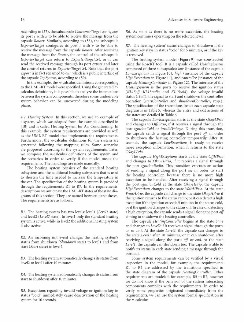
The heating system model (Figure 9) was constructedusing the RoseRT tool. It is a capsule called HeatingSystemcomposed of three subcapsules: low (instance of the capsuleLowExceptions in Figure 10), high (instance of the capsuleHighExceptions in Figure 11), and controller (instance of thecapsule HeatingController in Figure 12). The interface of theHeatingSystem is the ports to receive the ignition status(KL15off, KL15radio, and KL15cold), the voltage invalidstatus (iVolt), the signal to start and shutdown the controlleroperation (startController and shutdownController, resp.).The specification of the transitions inside each capsule statediagram is in Table 5; whereas the entry and exit actions ofthe states are detailed in Table 6.
The capsule LowExceptions starts at the state OkayLPrioand changes to OffLPrio, if it receives a signal through theport ignitionCold or invalidVoltage. During this transition,the capsule sends a signal through the port off in orderto shutdown the heating controller temporarily. After 10seconds, the capsule LowExceptions is ready to receivemore exception information, when it returns to the stateOkayLPrio.
The capsule HighExceptions starts at the state OffHPrioand changes to OkayHPrio, if it receives a signal throughthe port ignitionRadio. This transition executes an actionof sending a signal along the port on in order to startthe heating controller, because there is no more highexception to be handled. After receiving a signal throughthe port ignitionCold at the state OkayHPrio, the capsuleHighExceptions changes to the state WaitHPrio. At the stateWaitHPrio, the capsule can change to the state OkayHPrio ifthe ignition returns to the status radio; or it can detect a highexception if the ignition exceeds 5 minutes in the status cold,or if the ignition changes to the status off. In case of detectinga high exception, the capsule sends a signal along the port offaiming to shutdown the heating controller.
The capsule HeatingController begins at the state Startand changes to Level2 if it receives a signal through the portson or init. At the state Level2, the capsule can changes tothe state Level1 after 10 minutes, or it can shutdown afterreceiving a signal along the ports off or end. At the stateLevel1, the capsule can shutdown too. The capsule is able tonotify its status in each state sending a message through theport out.
Some system requirements can be verified by a visualinspection in the model, for example, the requirementsR1 to R4 are addressed by the transitions specified inthe state diagram of the capsule HeatingController. Otherrequirements are modeled, for example, R5 to R7, howeverwe do not know if the behavior of the system interactingcomponents complies with the requirements. In order toverify some properties originated immediately from therequirements, we can use the system formal specification inthe π-calculus.
Advances in Software Engineering 17
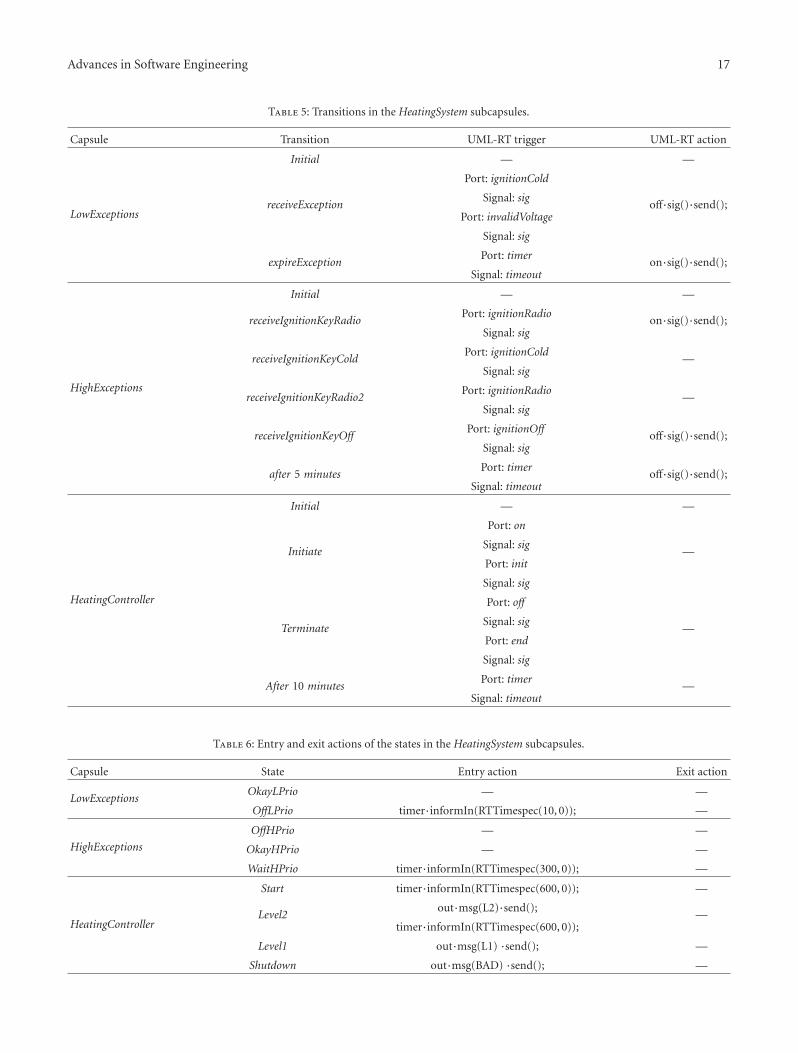
Table 5: Transitions in the HeatingSystem subcapsules.
Capsule Transition UML-RT trigger UML-RT action
LowExceptions
Initial — —
receiveException
Port: ignitionCold
off·sig()·send();Signal: sig
Port: invalidVoltage
Signal: sig
expireExceptionPort: timer
on·sig()·send();Signal: timeout
HighExceptions
Initial — —
receiveIgnitionKeyRadioPort: ignitionRadio
on·sig()·send();Signal: sig
receiveIgnitionKeyColdPort: ignitionCold
—Signal: sig
receiveIgnitionKeyRadio2Port: ignitionRadio
—Signal: sig
receiveIgnitionKeyOffPort: ignitionOff
off·sig()·send();Signal: sig
after 5 minutesPort: timer
off·sig()·send();Signal: timeout
HeatingController
Initial — —
Initiate
Port: on
—Signal: sig
Port: init
Signal: sig
Terminate
Port: off
—Signal: sig
Port: end
Signal: sig
After 10 minutesPort: timer
—Signal: timeout
Table 6: Entry and exit actions of the states in the HeatingSystem subcapsules.
Capsule State Entry action Exit action
LowExceptionsOkayLPrio — —
OffLPrio timer·informIn(RTTimespec(10, 0)); —
HighExceptions
OffHPrio — —
OkayHPrio — —
WaitHPrio timer·informIn(RTTimespec(300, 0)); —
HeatingController
Start timer·informIn(RTTimespec(600, 0)); —
Level2out·msg(L2)·send();
—timer·informIn(RTTimespec(600, 0));
Level1 out·msg(L1) ·send(); —
Shutdown out·msg(BAD) ·send(); —
18 Advances in Software Engineering
The π-calculus definitions of the heating system areprovided below; however we omit the capsule name in eachstate name due to space limitation
HeatingSystem(KL15radio,KL15cold,
KL15off , iVolt, startController,
shutdownController,heatingStatus)
= new on, off(HeatingController〈Set1Ref〉| LowExceptions〈Set2Ref〉| HighExceptions〈Set3Ref〉),
(60)
where
Set1Ref = {startController, shutdownController,on, off ,heatingStatus
},
Set2Ref = {KL15cold, iVolt, on, off},Set3Ref = {KL15radio,KL15cold,KL15off , on, off}.
(61)
Declaring Set1 = {init, end, on, off , out} as the input setof HeatingController definition, we have
HeatingController(List1) = Start〈Set1〉Start(Set1)
= (on + init) · Level2〈Set1〉 + τ · Shutdown〈Set1〉Level2(Set1)
= out〈L2〉 · ((off + end) · Shutdown〈Set1〉+τ · Level1〈Set1〉)
Level1(Set1)
= out〈L1〉 · ((off + end) · Shutdown〈Set1〉)
Shutdown(Set1)
= out〈BAD〉 · ((on + init) · Level1〈Set1〉). (62)
Declaring et2 = {ignitionCold, invalidVoltage, on, off}as the input set of LowExceptions definition, we have
LowExceptions(Set2) = OkayLPrio〈Set2〉OkayLPrio(Set2) = (ignitionCold + invalidVoltage
)
· off ·OffLPrio〈Set2〉OffLPrio(Set2) = τ · on ·OkayLPrio〈Set2〉.
(63)
Declaring Set3 = {ignitionRadio, ignitionCold,ignitionOff, on, off} as the input set of HighExceptionsdefinition, we have
HighExceptions(Set3)
= OffHPrio〈Set3〉OffHPrio(Set3)
= ignitionRadio · on ·OkayHPrio〈Set3〉OkayHPrio(Set3)
= ignitionCold ·WaitHPrio〈Set3〉WaitHPrio(Set3)
= ignitionRadio ·OkayHPrio〈Set3〉 + ignitionOff
· off ·OffHPrio〈Set3〉 + τ · off
·OffHPrio〈Set3〉.(64)
After obtaining the definitions of the components in themodel, it is desirable to verify its properties. In order to verifythe requirements R5 and R6, we assume the scenario wherean external actor sends a startController event and, later, itsends an iVolt event. The scenario can be specified as
Scenario1 = startController · heatingStatus(s1)
· iVolt · heatingStatus(s2) · heatingStatus(s3).(65)
After the startController event, the information that thesystem is at the level2 is expected, so s1 will receive “L2”. Afterthe iVolt event, the information that the system is shutdownis due, so s2 will receive “BAD”. After the timeout of the lowexception (in this case, the invalid voltage), the informationthat the system is at the level2 is waited, so s3 will be “L2”,because the requirement R6 specifies that the system has toreturn to the selected level after the exceptions.
Composing the heating system and the scenario, weobtain
HeatingSystem(KL15radio,KL15cold,KL15off , iVolt,
startController, shutdowController,
heatingStatus) | Scenario1.
(66)
Using (60) and (65), we have
new on, off(HeatingController〈Set1Ref〉| LowExceptions〈Set2Ref〉| HighExceptions〈Set3Ref〉)
|(startController · heatingStatus(s1)
· iVolt · heatingStatus(s2)
·heatingStatus(s3)).
(67)
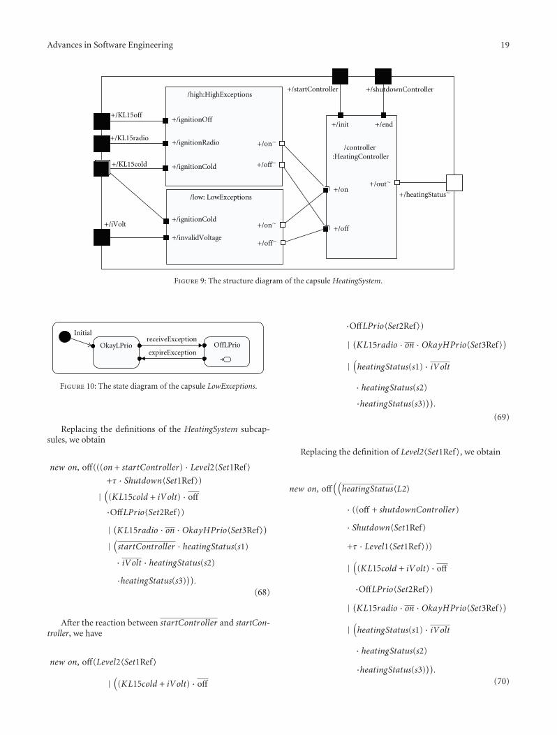
Advances in Software Engineering 19
+/heatingStatus∼
+/KL15off
+/KL15cold
+/KL15radio
+/iVolt
+/startController +/shutdownController
/controller :HeatingController
+/on
+/off
+/out∼
+/init
/high:HighExceptions
+/ignitionOff
+/ignitionCold
+/ignitionRadio +/on∼
+/off∼
/low: LowExceptions
+/invalidVoltage
+/ignitionCold
+/off∼
+/on∼
+/end
Figure 9: The structure diagram of the capsule HeatingSystem.
OkayLPrio OffLPrio
Initial
expireException
receiveException
Figure 10: The state diagram of the capsule LowExceptions.
Replacing the definitions of the HeatingSystem subcap-sules, we obtain
new on, off(((on + startController) · Level2〈Set1Ref〉+τ · Shutdown〈Set1Ref〉)
|(
(KL15cold + iVolt) · off
·OffLPrio〈Set2Ref〉)
| (KL15radio · on ·OkayHPrio〈Set3Ref〉)
|(startController · heatingStatus(s1)
· iVolt · heatingStatus(s2)
·heatingStatus(s3))).
(68)
After the reaction between startController and startCon-troller, we have
new on, off(Level2〈Set1Ref〉
|(
(KL15cold + iVolt) · off
·OffLPrio〈Set2Ref〉)
| (KL15radio · on ·OkayHPrio〈Set3Ref〉)
|(heatingStatus(s1) · iVolt
· heatingStatus(s2)
·heatingStatus(s3))).
(69)
Replacing the definition of Level2〈Set1Ref〉, we obtain
new on, off((heatingStatus〈L2〉
· ((off + shutdownController)
· Shutdown〈Set1Ref〉
+τ · Level1〈Set1Ref〉))
|(
(KL15cold + iVolt) · off
·OffLPrio〈Set2Ref〉)
| (KL15radio · on ·OkayHPrio〈Set3Ref〉)
|(heatingStatus(s1) · iVolt
· heatingStatus(s2)
·heatingStatus(s3))).
(70)
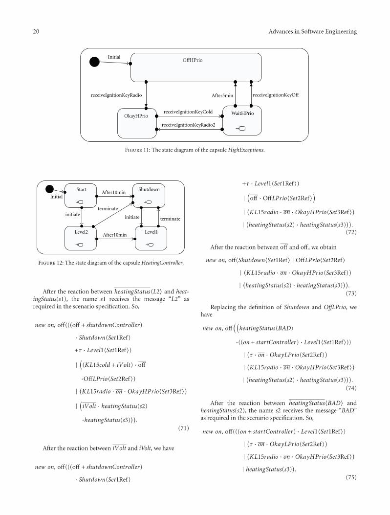
20 Advances in Software Engineering
OffHPrio
OkayHPrio WaitHPrio
Initial
receiveIgnitionKeyRadio2
After5min receiveIgnitionKeyOffreceiveIgnitionKeyRadio
receiveIgnitionKeyCold
Figure 11: The state diagram of the capsule HighExceptions.
Start Shutdown
Level2 Level1
Initial
terminateinitiate
After10min
After10min
terminateinitiate
Figure 12: The state diagram of the capsule HeatingController.
After the reaction between heatingStatus〈L2〉 and heat-ingStatus(s1), the name s1 receives the message “L2” asrequired in the scenario specification. So,
new on, off(((off + shutdownController)
· Shutdown〈Set1Ref〉+τ · Level1〈Set1Ref〉)
|(
(KL15cold + iVolt) · off
·OffLPrio〈Set2Ref〉)
| (KL15radio · on ·OkayHPrio〈Set3Ref〉)
|(iVolt · heatingStatus(s2)
·heatingStatus(s3))).
(71)
After the reaction between iVolt and iVolt, we have
new on, off(((off + shutdownController)
· Shutdown〈Set1Ref〉
+τ · Level1〈Set1Ref〉)
|(
off ·OffLPrio〈Set2Ref〉)
| (KL15radio · on ·OkayHPrio〈Set3Ref〉)
| (heatingStatus(s2) · heatingStatus(s3))).
(72)
After the reaction between off and off , we obtain
new on, off(Shutdown〈Set1Ref〉 | OffLPrio〈Set2Ref〉| (KL15radio · on ·OkayHPrio〈Set3Ref〉)
| (heatingStatus(s2) · heatingStatus(s3))).
(73)
Replacing the definition of Shutdown and OffLPrio, wehave
new on, off((heatingStatus〈BAD〉
·((on + startController) · Level1〈Set1Ref〉))
| (τ · on ·OkayLPrio〈Set2Ref〉)
| (KL15radio · on ·OkayHPrio〈Set3Ref〉)
| (heatingStatus(s2) · heatingStatus(s3))).
(74)
After the reaction between heatingStatus〈BAD〉 andheatingStatus(s2), the name s2 receives the message “BAD”as required in the scenario specification. So,
new on, off(((on + startController) · Level1〈Set1Ref〉)
| (τ · on ·OkayLPrio〈Set2Ref〉)
| (KL15radio · on ·OkayHPrio〈Set3Ref〉)
| heatingStatus(s3)).
(75)
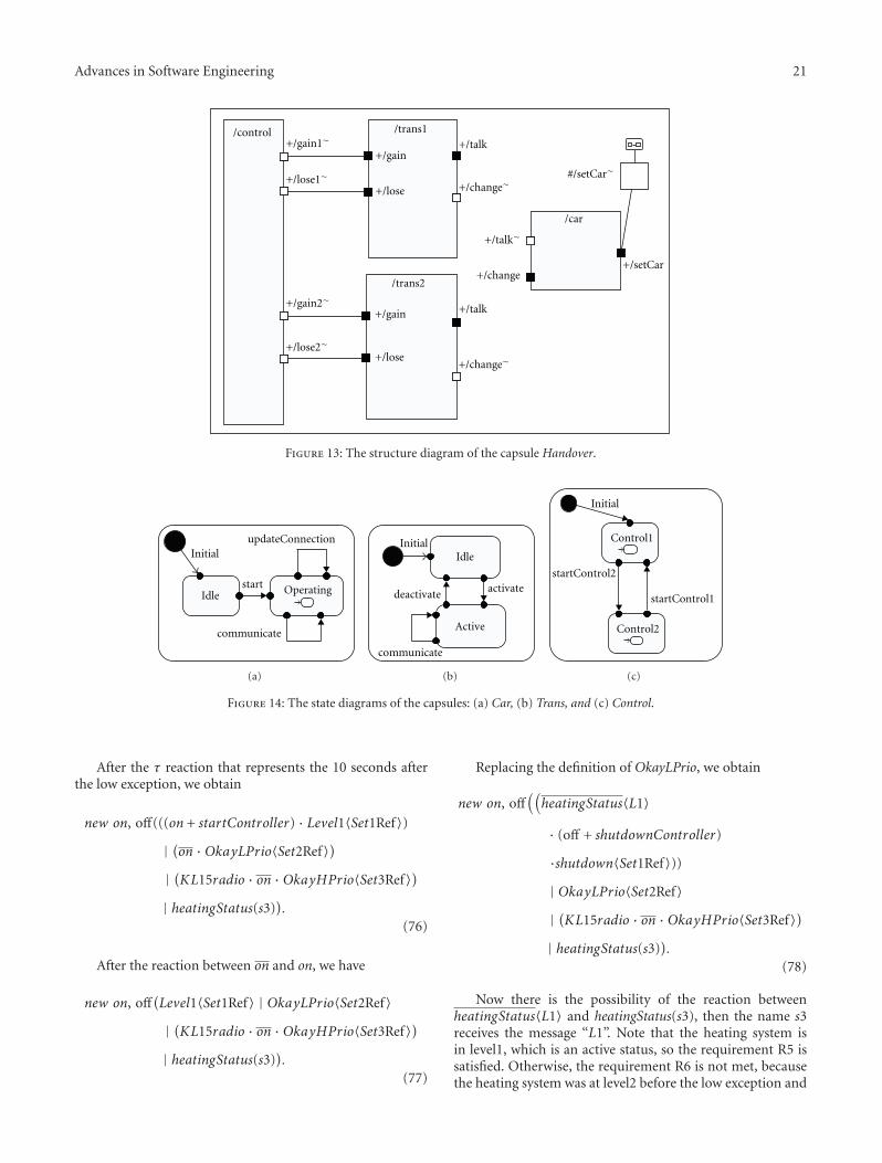
Advances in Software Engineering 21
/control+/gain1∼
+/lose1∼
+/gain2∼
+/lose2∼
/trans1+/talk
+/change∼
+/gain
+/lose
/car
+/change
+/talk∼
+/setCar
/trans2
+/talk
+/change∼
+/gain
+/lose
#/setCar∼
Figure 13: The structure diagram of the capsule Handover.
OperatingIdle
communicate
updateConnectionInitial
start
(a)
Idle
Active
Initial
communicate
deactivateactivate
(b)
Control1
Control2
startControl1
Initial
startControl2
(c)
Figure 14: The state diagrams of the capsules: (a) Car, (b) Trans, and (c) Control.
After the τ reaction that represents the 10 seconds afterthe low exception, we obtain
new on, off(((on + startController) · Level1〈Set1Ref〉)
| (on ·OkayLPrio〈Set2Ref〉)
| (KL15radio · on ·OkayHPrio〈Set3Ref〉)
| heatingStatus(s3)).
(76)
After the reaction between on and on, we have
new on, off(Level1〈Set1Ref〉 | OkayLPrio〈Set2Ref〉| (KL15radio · on ·OkayHPrio〈Set3Ref〉)
| heatingStatus(s3)).
(77)
Replacing the definition of OkayLPrio, we obtain
new on, off((heatingStatus〈L1〉
· (off + shutdownController)
·shutdown〈Set1Ref〉))
| OkayLPrio〈Set2Ref〉| (KL15radio · on ·OkayHPrio〈Set3Ref〉)
| heatingStatus(s3)).
(78)
Now there is the possibility of the reaction betweenheatingStatus〈L1〉 and heatingStatus(s3), then the name s3receives the message “L1”. Note that the heating system isin level1, which is an active status, so the requirement R5 issatisfied. Otherwise, the requirement R6 is not met, becausethe heating system was at level2 before the low exception and
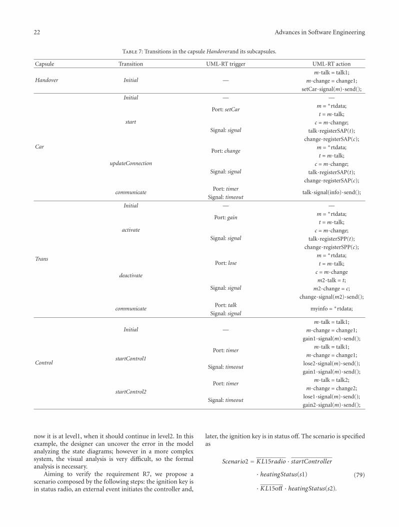
22 Advances in Software Engineering
Table 7: Transitions in the capsule Handoverand its subcapsules.
Capsule Transition UML-RT trigger UML-RT action
Handover Initial —m·talk = talk1;
m·change = change1;
setCar·signal(m)·send();
Car
Initial — —
start
Port: setCarm = ∗rtdata;
t =m·talk;
Signal: signalc =m·change;
talk·registerSAP(t);
change·registerSAP(c);
updateConnection
Port: changem = ∗rtdata;
t =m·talk;
Signal: signalc =m·change;
talk·registerSAP(t);
change·registerSAP(c);
communicatePort: timer
talk·signal(info)·send();Signal: timeout
Trans
Initial — —
activate
Port: gainm = ∗rtdata;
t =m·talk;
Signal: signalc =m·change;
talk·registerSPP(t);
change·registerSPP(c);
deactivate
Port: losem = ∗rtdata;
t =m·talk;
c =m·change
Signal: signalm2·talk = t;
m2·change = c;change·signal(m2)·send();
communicatePort: talk
myinfo = ∗rtdata;Signal: signal
Control
Initial —m·talk = talk1;
m·change = change1;
gain1·signal(m)·send();
startControl1
Port: timerm·talk = talk1;
m·change = change1;
Signal: timeoutlose2·signal(m)·send();
gain1·signal(m)·send();
startControl2
Port: timerm·talk = talk2;
m·change = change2;
Signal: timeoutlose1·signal(m)·send();
gain2·signal(m)·send();
now it is at level1, when it should continue in level2. In thisexample, the designer can uncover the error in the modelanalyzing the state diagrams; however in a more complexsystem, the visual analysis is very difficult, so the formalanalysis is necessary.
Aiming to verify the requirement R7, we propose ascenario composed by the following steps: the ignition key isin status radio, an external event initiates the controller and,
later, the ignition key is in status off. The scenario is specifiedas
Scenario2 = KL15radio · startController· heatingStatus(s1)
· KL15off · heatingStatus(s2).
(79)
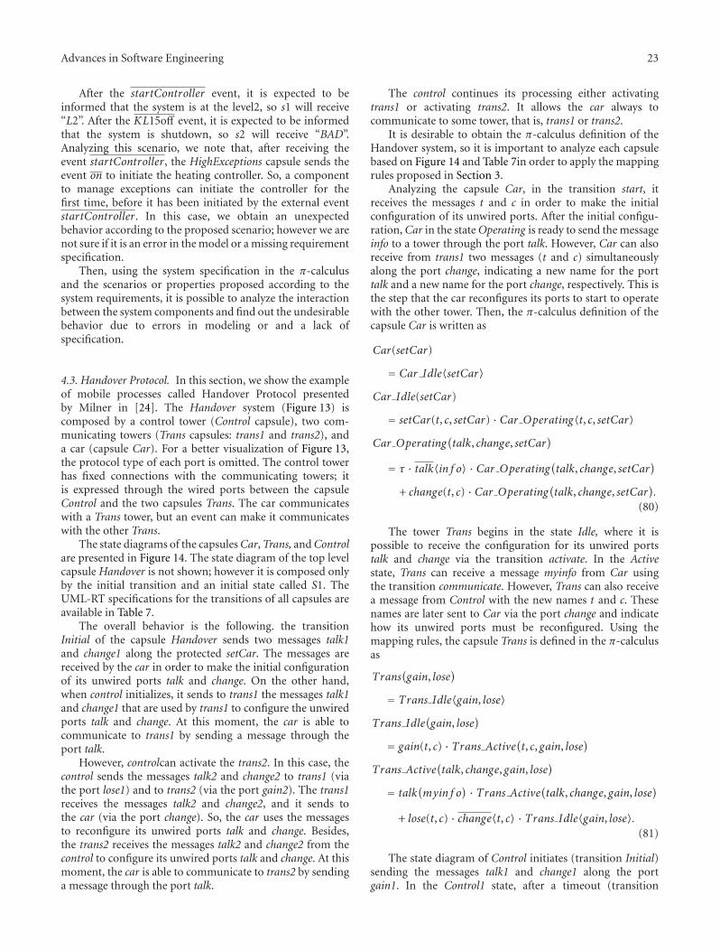
Advances in Software Engineering 23
After the startController event, it is expected to beinformed that the system is at the level2, so s1 will receive“L2”. After the KL15off event, it is expected to be informedthat the system is shutdown, so s2 will receive “BAD”.Analyzing this scenario, we note that, after receiving theevent startController, the HighExceptions capsule sends theevent on to initiate the heating controller. So, a componentto manage exceptions can initiate the controller for thefirst time, before it has been initiated by the external eventstartController. In this case, we obtain an unexpectedbehavior according to the proposed scenario; however we arenot sure if it is an error in the model or a missing requirementspecification.
Then, using the system specification in the π-calculusand the scenarios or properties proposed according to thesystem requirements, it is possible to analyze the interactionbetween the system components and find out the undesirablebehavior due to errors in modeling or and a lack ofspecification.
4.3. Handover Protocol. In this section, we show the exampleof mobile processes called Handover Protocol presentedby Milner in [24]. The Handover system (Figure 13) iscomposed by a control tower (Control capsule), two com-municating towers (Trans capsules: trans1 and trans2), anda car (capsule Car). For a better visualization of Figure 13,the protocol type of each port is omitted. The control towerhas fixed connections with the communicating towers; itis expressed through the wired ports between the capsuleControl and the two capsules Trans. The car communicateswith a Trans tower, but an event can make it communicateswith the other Trans.
The state diagrams of the capsules Car, Trans, and Controlare presented in Figure 14. The state diagram of the top levelcapsule Handover is not shown; however it is composed onlyby the initial transition and an initial state called S1. TheUML-RT specifications for the transitions of all capsules areavailable in Table 7.
The overall behavior is the following. the transitionInitial of the capsule Handover sends two messages talk1and change1 along the protected setCar. The messages arereceived by the car in order to make the initial configurationof its unwired ports talk and change. On the other hand,when control initializes, it sends to trans1 the messages talk1and change1 that are used by trans1 to configure the unwiredports talk and change. At this moment, the car is able tocommunicate to trans1 by sending a message through theport talk.
However, controlcan activate the trans2. In this case, thecontrol sends the messages talk2 and change2 to trans1 (viathe port lose1) and to trans2 (via the port gain2). The trans1receives the messages talk2 and change2, and it sends tothe car (via the port change). So, the car uses the messagesto reconfigure its unwired ports talk and change. Besides,the trans2 receives the messages talk2 and change2 from thecontrol to configure its unwired ports talk and change. At thismoment, the car is able to communicate to trans2 by sendinga message through the port talk.
The control continues its processing either activatingtrans1 or activating trans2. It allows the car always tocommunicate to some tower, that is, trans1 or trans2.
It is desirable to obtain the π-calculus definition of theHandover system, so it is important to analyze each capsulebased on Figure 14 and Table 7in order to apply the mappingrules proposed in Section 3.
Analyzing the capsule Car, in the transition start, itreceives the messages t and c in order to make the initialconfiguration of its unwired ports. After the initial configu-ration, Car in the state Operating is ready to send the messageinfo to a tower through the port talk. However, Car can alsoreceive from trans1 two messages (t and c) simultaneouslyalong the port change, indicating a new name for the porttalk and a new name for the port change, respectively. This isthe step that the car reconfigures its ports to start to operatewith the other tower. Then, the π-calculus definition of thecapsule Car is written as
Car(setCar)
= Car Idle〈setCar〉Car Idle(setCar)
= setCar(t, c, setCar) · Car Operating〈t, c, setCar〉Car Operating
(talk, change, setCar
)
= τ · talk〈in f o〉 · Car Operating(talk, change, setCar)
+ change(t, c) · Car Operating(talk, change, setCar).
(80)
The tower Trans begins in the state Idle, where it ispossible to receive the configuration for its unwired portstalk and change via the transition activate. In the Activestate, Trans can receive a message myinfo from Car usingthe transition communicate. However, Trans can also receivea message from Control with the new names t and c. Thesenames are later sent to Car via the port change and indicatehow its unwired ports must be reconfigured. Using themapping rules, the capsule Trans is defined in the π-calculusas
Trans(gain, lose
)
= Trans Idle〈gain, lose〉Trans Idle
(gain, lose
)
= gain(t, c) · Trans Active(t, c, gain, lose)
Trans Active(talk, change, gain, lose
)
= talk(myin f o
) · Trans Active(talk, change, gain, lose)
+ lose(t, c) · change〈t, c〉 · Trans Idle〈gain, lose〉.(81)
The state diagram of Control initiates (transition Initial)sending the messages talk1 and change1 along the portgain1. In the Control1 state, after a timeout (transition
24 Advances in Software Engineering
startControl2), Control can send the messages talk2 andchange2 through the port lose1, and later through the portgain2. In a similar way, in the Control2 state, after a timeout(transition startControl1), Control can send the messagestalk1 and change1 through the port lose2, and later throughthe port gain1. In this way, the transition startControl2indicates that trans2 is apt to talk with the car; while thetransition startControl1 indicates that trans1 is now readyto talk with the car. Then, the π-calculus definition of thecapsule Control is written as
Control(gain1, lose1, gain2, lose2
)
= gain1〈talk1, change1〉· Control Control1〈gain1, lose1, gain2, lose2〉
Control Control1(gain1, lose1, gain2, lose2
)
= τ · lose1〈talk2, change2〉 · gain2〈talk2, change2〉· Control Control2〈gain1, lose1, gain2, lose2〉
Control Control2(gain1, lose1, gain2, lose2
)
= τ · lose2〈talk1, change1〉 · gain1〈talk1, change1〉· Control Control2〈gain1, lose1, gain2, lose2〉.
(82)
Finally, the Handover system is defined in the π-calculusas the parallel composition of the definition of its statediagram and its structure diagram definition. The statediagram definition is the possibility to send the messagestalk1 and change1 along the port setCar. The structurediagram definition includes a reference to each subcapsuledefinition. So, the Handoverdefinition is written as
Handover()
= new(setCar, zgain1, zlose1, zgain2, zlose2
)
(Car〈setCar〉 | Trans〈zgain1, zlose1〉| Trans〈zgain2, zlose2〉| Control〈zgain1, zlose1, zgain2, zlose2〉
| setCar〈talk1, change1〉).
(83)
It is important to understand each term in the parallelcomposition shown in (83). The first term represents thesubcapsule car (instance of Car). The second and thethird terms represent the subcapsules trans1 and trans2(instance of Trans), respectively. The fourth term indicatesthe subcapsule control (instance of Control). The last termis the definition of the Handover state diagram. Besides,the names setCar, zgain1, zlose1, zgain2, zlose2 are used torepresent the wired connections between the subcapsules inthe π-calculus definitions. For example, the name zgain1allows the communication between the port gain1 of controland the port gain of trans1, because the subcapsule’s ports arerenamed to the same name zgain1.
The Handover system is an example of mobile processes,where the messages received by a process in a communicationcan be used to rename its ports and, consequently, to allowthe reconfiguration of its connections with other processes.Besides, the present example includes the need of thecommunication of more than one message at a time betweenprocesses, which emphasizes the importance of the polyadicπ-calculus approach.
5. Comments and Conclusions
We propose a formal semantics to the UML-RT commu-nicating elements through the mapping from the UML-RTto the polyadic π-calculus. The UML-RT is a UML profilewidely used for the real-time system modeling, and the π-calculus is one of the main formalisms of the concurrentsystems modeling. The proposed mapping from the UML-RT to the π-calculus is a practical approach of π-calculus,and it enables the use of formal methods during systemdevelopment.
We described three examples. In the first example,we explained how to obtain the π-calculus definition ofa UML-RT model using the proposed mapping rules.In the second example, we illustrated the possibility toformally verify system requirements using the π-calculusdefinitions of the model and some scenarios specified fromthe requirements. During the verification process, we showedthat we can uncover some undesirable behavior, which areconsequences of a poor system specification or an errorintroduced during the modeling phase. Finally, in the thirdexample, we present the Handover protocol. This exampledemonstrates the importance of the reconfiguration of theconnections between processes and the need of modeling ofcommunication of more than one message at a time, whichis well addressed using the polyadic π-calculus.
A real-time system designer who desires to formallyreason about a UML-RT model can apply the proposedmapping rules on the UML-RT model to obtain the cor-responding π-calculus definitions. Afterwards, the designercan manipulate the π-calculus definitions to explore possibleexecution paths and find situations that can cause functionalproblems or inconsistencies with functional requirements.Problems and inconsistencies include deadlock and non-satisfaction of safety properties. This practice increases theconfidence in the system development, because it anticipatesthe detection of problems in the modeling phase.
Two main contributions of the mapping proposed inthis paper are due to polyadic π-calculus mobility, which isprovided by name reconfiguration. The first contribution isthe reuse of the capsule definition. For example, if a parentcapsule has three instances of the same subcapsule, it isnecessary to write one definition in the π-calculus for thesubcapsule, and this definition is referenced three times bythe parent capsule. It helps to reduce the number of the π-calculus definitions for the system. The second contributionof the name reconfiguration is the ability to represent thedynamic configuration of the unwired ports. It is importantbecause a UML-RT capsule can rename an unwired port
Advances in Software Engineering 25
during its state diagram execution, as it is shown in the firstexample.
Other contributions include the option for the polyadicπ-calculus, which represents the communication of morethan one message at a time. Besides, the proposed map-ping deals with the following UML-RT concepts not yetaddressed: the entry and the exit actions of a state, thecomposite states, and the transition chains.
In order to test the consistency of the mapping rules, weused the mapping to obtain π-calculus models of other UMLmodels, besides the examples presented in this work. Forinstance, we have used the mapping on a system composedby a pair of semaphores to prove that two green lights of bothsemaphores cannot occur at the same time.
Future research directions include the improvement ofthe mapping rules to represent other UML-RT elements,such as history junction points, the guard conditions, andthe capsule cardinalities. An interesting topic to investigateis to capture, from the UML-RT sequence diagram, the π-calculus definitions of the desirable scenarios to be met bythe system under design. Another research issue is the studyof formal approaches to represent the UML-RT timeouts, inorder to be able to verify the time constraints of the modeledsystem.
References
[1] O. R. Ribeiro, J. M. Fernandes, and L. F. Pinto, “Modelchecking embedded systems with PROMELA,” in Proceedingsof the 12th IEEE International Conference and Workshops onthe Engineering of Computer-Based Systems (ECS ’05), pp. 378–385, Greenbelt, Md, USA, April 2005.
[2] L. A. Cortes, P. Eles, and Z. Peng, “Verification of embeddedsystems using a petri net based representation,” in Proceedingsof the 13th International Symposium on System Level Synthesis(ISSS ’00), pp. 149–155, Madrid, Spain, 2000.
[3] J. Baeten and J. A. Bergstra, “Six issues concerning futuredirections in concurrency research,” ACM Computing Surveys,vol. 28, 1996.
[4] J. P. Bowen and M. G. Hinchey, “Seven more myths of formalmethods,” IEEE Software, vol. 12, no. 4, pp. 34–41, 1995.
[5] M. Thomas, “Formal methods and their role in developingsafe systems,” High Integrity Systems Journal, vol. 1, no. 5, pp.447–451, 1996.
[6] RTCA, Incorporated. Software Considerations in AirborneSystems and Equipment Certification (DO178-B).
[7] R. S. Pressman, Software Engineering: A Practitioner’sApproach, Pearson, Delhi, India, 2005.
[8] OMG Unified Modeling Language Specification version 1.5.OMG document formal/2003-03-01, 2003.
[9] A. Gherbi and F. Khendek, “UML profiles for real-timesystems and their applications,” Journal of Object Technology,vol. 5, no. 4, pp. 149–169, 2006.
[10] L. Bichler, A. Radermacher, and A. Schurr, “Evaluating UMLextensions for modeling real-time systems,” in Proceedingsof the 7th IEEE International Workshop on Object-OrientedReal-Time Dependable Systems (WORDS ’02), p. 271.1, IEEEComputer Society, San Diego, Calif, USA, January 2002.
[11] B. Selic and J. Rumbaugh, Using UML for Modeling RealTimeSystems, Rational Software Corporation, 1998.
[12] IBM Rational Rose RealTime Tool. Version 6.5.
[13] OMG Unified Modeling Language Specification version 2.1.2.OMG document formal/2007-11-04, 2007.
[14] B. Selic, “UML 2: a model-driven development tool,” IBMSystems Journal, vol. 45, no. 3, pp. 607–620, 2006.
[15] IBM Rational Rose Technical Developer Tool, Version7.0. Product specifications, http://www.developers.net/ibmshowcase/view/1847.
[16] J. A. H. Terriza, K. B. Akhlaki, and M. I. C. Tunon, “Combiningthe description features of UML-RT and CSP+T specificationsapplied to a complete design of real-time systems,” Interna-tional Journal of Information Technology, vol. 2, no. 3, 2005.
[17] C. Fischer, E.-R. Olderog, and H. Wehrheim, “A CSP view onUML-RT structure diagrams,” in Proceedings of FundamentalApproaches to Software Engineering (FASE ’01), 2001.
[18] G. Engels, J. M. Kuster, R. Heckel, et al., “A methodologyfor specifying and analyzing consistency of object-orientedbehavioral models,” in Proceedings of the 8th European SoftwareEngineering Conference (ESEC) and ACM SIGSOFT Sympo-sium on the Foundations of Software Engineering (FSE-9),Austria, 2001.
[19] R. Ramos, A. Sampaio, and A. Mota, “A semantics for UML-RT active classes via mapping into circus,” in Proceedings of the7th IFIP WG 6.1 International Conference on Formal Methodsfor Open Object-Based Distributed Systems (FMOODS ’05),vol. 3535 of Lecture Notes in Computer Science, pp. 99–114,Athens, June 2005.
[20] C. A. R. Hoare, Communicating Sequential Processes, Prentice-Hall, Englewood Cliffs, NJ, USA, 1985.
[21] R. Milner, Communication and Concurrency, Prentice-Hall,Englewood Cliffs, NJ, USA, 1989.
[22] A. Cavalcanti, A. Sampaio, and J. Woodcock, “Refinementin circus,” in Proceedings of the International Symposium ofFormal Methods Europe, vol. 2391 of Lecture Notes In ComputerScience, Springer, 2002.
[23] A. Knapp, S. Merz, and C. Rauh, “Model checking timedUML state machines and collaborations,” in Proceedings of the7th International Symposium on Formal Techniques in Real-Time and Fault-Tolerant Systems, vol. 2469 of Lecture Notes InComputer Science, pp. 395–416, 2002.
[24] R. Milner, Communicating and Mobile Systems: The π-Calculus, Cambridge University Press, Cambridge, UK, 1999.
[25] J. M. Bezerra and C. M. Hirata, “A semantics for UML-RT using π-calculus,” in Proceedings of the 18th IEEE/IFIPInternational Workshop on Rapid System Prototyping (RSP ’07),pp. 75–82, Porto Alegre, Brazil, May 2007.
[26] G.-L. Ferrari, S. Gnesi, U. Montanari, and M. Pistore,“A model-checking verification environment for mobileprocesses,” ACM Transactions on Software Engineering andMethodology, vol. 12, no. 4, pp. 440–473, 2003.
[27] J. Parrow, “An introduction to the pi-calculus,” in Handbookof Process Algebra, Bergstra, Ponse, and Smolka, Eds., pp. 479–543, Elsevier Science, Amsterdam, The Netherlands, 2001.
[28] L. Wischik, “New directions in implementing the pi-calculus,”in Cabernet Radicals Workshop, 2002.
[29] S. D. Zilio, “Mobile processes: a commented bibliography,”in Proceedings of the 4th Summer School on Modelling andVerification of Parallel Processes, vol. 2067 of Lecture Notes inComputer Science, pp. 206–222, Springer, 2001.
[30] M. Spivey, The Z Notation: A Reference Manual, Prentice-Hall,Englewood Cliffs, NJ, USA, 1992.
[31] G. Smith, The Object-Z Specification Language, Advancesin Formal Methods Series, Kluwer Academic Publishers,Dordrecht, The Netherlands, 1999.
26 Advances in Software Engineering
[32] H. Miao, L. Liu, and L. Li, “Formalizing UML models withObject-Z,” in Proceedings of the 4th International Conferenceon Formal Engineering Methods: Formal Methods and SoftwareEngineering, pp. 523–534, Springer, 2002.
[33] S. Kim and D. Carrington, “A formal model of the UML meta-model: the UML state machine and its integrity constraints,”in Proceedings of the 2nd International Conference of B and ZUsers on Formal Specification and Development in Z and B, pp.497–516, Springer, 2002.
[34] K. Taguchi, J. S. Dong, and G. Ciobanu, “Relating π-calculusto Object-Z,” in Proceedings of the 9th IEEE InternationalConference on Engineering of Complex Computer Systems(ICECCS ’04), pp. 97–106, Florence, Italy, April 2004.
[35] K. Taguchi and J. Dong, “An overview of mobile Object-Z,” in Proceedings of the 4th International Conference onFormal Engineering Methods: Formal Methods and SoftwareEngineering, pp. 144–155, Springer, 2002.
[36] A. Rarau and K. Pusztai, “An experience with using Z formobile computing,” in Proceedings of Software Engineering andApplications, Cambridge, Mass, USA, 2002.

Submit your manuscripts athttp://www.hindawi.com
Computer Games Technology
International Journal of
Hindawi Publishing Corporationhttp://www.hindawi.com Volume 2014
Hindawi Publishing Corporationhttp://www.hindawi.com Volume 2014
Distributed Sensor Networks
International Journal of
Advances in
FuzzySystems
Hindawi Publishing Corporationhttp://www.hindawi.com
Volume 2014
International Journal of
ReconfigurableComputing
Hindawi Publishing Corporation http://www.hindawi.com Volume 2014
Hindawi Publishing Corporationhttp://www.hindawi.com Volume 2014
Applied Computational Intelligence and Soft Computing
Advances in
Artificial Intelligence
Hindawi Publishing Corporationhttp://www.hindawi.com Volume 2014
Advances inSoftware EngineeringHindawi Publishing Corporationhttp://www.hindawi.com Volume 2014
Hindawi Publishing Corporationhttp://www.hindawi.com Volume 2014
Electrical and Computer Engineering
Journal of
Journal of
Computer Networks and Communications
Hindawi Publishing Corporationhttp://www.hindawi.com Volume 2014
Hindawi Publishing Corporation
http://www.hindawi.com Volume 2014
Advances in
Multimedia
International Journal of
Biomedical Imaging
Hindawi Publishing Corporationhttp://www.hindawi.com Volume 2014
ArtificialNeural Systems
Advances in
Hindawi Publishing Corporationhttp://www.hindawi.com Volume 2014
RoboticsJournal of
Hindawi Publishing Corporationhttp://www.hindawi.com Volume 2014
Hindawi Publishing Corporationhttp://www.hindawi.com Volume 2014
Computational Intelligence and Neuroscience
Industrial EngineeringJournal of
Hindawi Publishing Corporationhttp://www.hindawi.com Volume 2014
Modelling & Simulation in EngineeringHindawi Publishing Corporation http://www.hindawi.com Volume 2014
The Scientific World JournalHindawi Publishing Corporation http://www.hindawi.com Volume 2014
Hindawi Publishing Corporationhttp://www.hindawi.com Volume 2014
Human-ComputerInteraction
Advances in
Computer EngineeringAdvances in
Hindawi Publishing Corporationhttp://www.hindawi.com Volume 2014
Related Documents