The 33st International Electric Propulsion Conference, The George Washington University, USA October 6 – 10, 2013 1 A Plan to Study the Radiated Emissions from a VASIMR ® Engine Exhaust Plume IEPC-2013-199 Presented at the 33rd International Electric Propulsion Conference, The George Washington University • Washington, D.C. • USA October 6 – 10, 2013 Matthew Giambusso 1 , Edgar A. Bering, III 2 , Gregg A. Edeen 3 University of Houston, Houston, Texas, 77204, USA and Mark D. Carter 4 , Christopher S. Olsen 5 , Jared P. Squire 6 Ad Astra Rocket Company, Webster, Texas, 77598, USA Abstract: A method to evaluate the radiated electromagnetic interference from a VAriable Specific Impulse Magnetoplasma Rocket (VASIMR ® ) propulsion system is presented. Emphasis is placed on the interference produced or transmitted through the exhaust plume of the rocket. The method involves experimental measurements within the plasma plume, receiving antenna measurements in the vacuum chamber, analytical modeling of plasma instabilities, and simulation. The primary goal of the study will be to assess the compliance of a VASIMR ® engine with the electromagnetic compatibility requirements of the International Space Station and other spacecraft standards. More generally, the study will explore the subject of instabilities in a plasma jet expanding through a magnetic nozzle. Nomenclature f ci , f ce = ion, electron cyclotron frequencies n e = electron number density f pi , f pe = ion, electron plasma frequencies Δn/n = plasma density fluctuation f LH , f UH = lower hybrid, upper hybrid frequencies ω = angular frequency f(v) = velocity distribution function x = position along ray path r = radius in cylindrical chamber coordinates D = dispersion relation z = axial chamber coordinate k = wave vector E = electric field vector Γ = wave growth rate B = magnetic field vector ρ = gyroradius σ = conductivity tensor 1 Graduate Student, Physics Department, [email protected] 2 Professor, Physics Department and Electrical and Computer Engineering Department, [email protected] 3 Graduate Student, Physics Department, [email protected] 4 Director of Technology, [email protected] 5 Senior Research Scientist, [email protected] 6 Director of Research, [email protected]

Welcome message from author
This document is posted to help you gain knowledge. Please leave a comment to let me know what you think about it! Share it to your friends and learn new things together.
Transcript

The 33st International Electric Propulsion Conference, The George Washington University, USA
October 6 – 10, 2013
1
A Plan to Study the Radiated Emissions from a VASIMR®
Engine Exhaust Plume
IEPC-2013-199
Presented at the 33rd International Electric Propulsion Conference,
The George Washington University • Washington, D.C. • USA
October 6 – 10, 2013
Matthew Giambusso1, Edgar A. Bering, III
2, Gregg A. Edeen
3
University of Houston, Houston, Texas, 77204, USA
and
Mark D. Carter4, Christopher S. Olsen
5, Jared P. Squire
6
Ad Astra Rocket Company, Webster, Texas, 77598, USA
Abstract: A method to evaluate the radiated electromagnetic interference from a
VAriable Specific Impulse Magnetoplasma Rocket (VASIMR®) propulsion system is
presented. Emphasis is placed on the interference produced or transmitted through the
exhaust plume of the rocket. The method involves experimental measurements within the
plasma plume, receiving antenna measurements in the vacuum chamber, analytical
modeling of plasma instabilities, and simulation. The primary goal of the study will be to
assess the compliance of a VASIMR®
engine with the electromagnetic compatibility
requirements of the International Space Station and other spacecraft standards. More
generally, the study will explore the subject of instabilities in a plasma jet expanding through
a magnetic nozzle.
Nomenclature
fci , fce = ion, electron cyclotron frequencies ne = electron number density
fpi , fpe = ion, electron plasma frequencies ∆n/n = plasma density fluctuation
fLH , fUH = lower hybrid, upper hybrid frequencies ω = angular frequency
f(v) = velocity distribution function x = position along ray path
r = radius in cylindrical chamber coordinates D = dispersion relation
z = axial chamber coordinate k = wave vector
E = electric field vector Γ = wave growth rate
B = magnetic field vector ρ = gyroradius
σ = conductivity tensor
1 Graduate Student, Physics Department, [email protected]
2 Professor, Physics Department and Electrical and Computer Engineering Department, [email protected]
3 Graduate Student, Physics Department, [email protected]
4 Director of Technology, [email protected]
5 Senior Research Scientist, [email protected]
6 Director of Research, [email protected]
The 33st International Electric Propulsion Conference, The George Washington University, USA
October 6 – 10, 2013
2
I. Introduction
he Aurora mission will consist of the VAriable Specific Impulse Magnetoplasma Rocket (VASIMR®) VF-
200™ operating as an attached payload on the International Space Station (ISS). The rocket must meet certain
limits of radiated electromagnetic interference (EMI). In this paper, we outline a plan to study the EMI from the
exhaust plume of the VASIMR® VX-200 prototype within its 150 m
3 vacuum facility at the Ad Astra Rocket
Company (AARC) located in Webster, TX. The study will include probe measurements within the plasma plume,
receiving antenna measurements in the vacuum chamber, analytical modeling of plasma instabilities and wave
propagation, and simulation. The paper is organized as follows: In the remainder of the introduction, we discuss the
radiated EMI compatibility requirements for ISS payloads and accepted EMI testing methods, followed by an
overview of the VASIMR® VX-200 laboratory prototype and the planned VF-200™ space propulsion system. In
Section II, we present methods to measure and model the EMI from the VX-200 engine, with subsections devoted
to: radio frequency waves injected from the couplers in the rocket core, macroscopic and microscopic instability
growth rates, nonlinear wave amplitude limits, simulating wave propagation, particle simulations, and receiving
antenna measurements.
A. Laboratory Setup & VASIMR®
Basics
A VASIMR® engine is a two-stage RF
driven magnetized plasma rocket. The first stage
(helicon) is a helicon plasma source. The second
stage (ICH) heats the ions using left hand
polarized slow mode waves launched from the
high field side of the ion cyclotron resonance.1
Two major elements of a VASIMR® engine are
the RF power processing systems and the high
magnetic field enabled by state-of-the-art
superconducting magnet technology. The unique
element of the VASIMR® technology resides in
the bore of the magnet and is referred to as the
rocket core. This is where the electromagnetics
and structure of the system are carefully
designed to couple RF power to the dense
magnetized plasma.
Figure 1 shows a conceptual schematic of a
single VASIMR®
thruster. A VF-200™ engine
is a specific embodiment of two such thrusters
with opposing magnetic polarity clustered such that they form a magnetic quadrupole. This nulls any torque in
earth’s magnetic field and greatly reduces any stray magnetic field strength around the spacecraft. The VF-200™ is
the flight design which will be operated as an attached payload on the ISS. In the meantime, EMI testing will begin
T
Figure 1. Schematic diagram of a VASIMR
® System
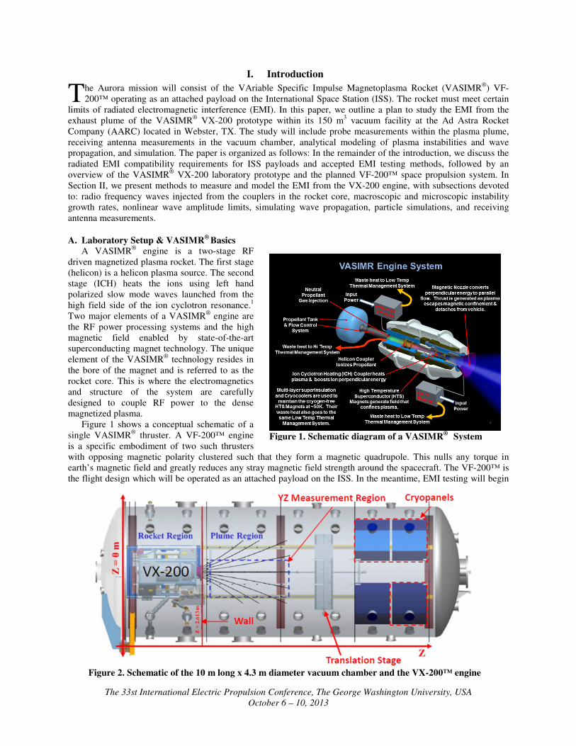
Figure 2. Schematic of the 10 m long x 4.3 m diameter vacuum chamber and the VX-200™ engine
The 33st International Electric Propulsion Conference, The George Washington University, USA
October 6 – 10, 2013
3
using the VX-200 laboratory device, which has been operated since 2009 in support of the VF-200™ design
process. The remainder of this section discusses the VX-200 and its laboratory configuration.
The VX-200 device is a 200 kW laboratory prototype that has been operated at specific impulses between 2000 s
and 5000 s, and thrusts up to 6 N. The magnetic field is generated by a cryogen-free, generation 1 (Nb-Ti)
superconducting magnet encased in a well-insulated cryostat surrounding the engine core. The magnet produces a
peak magnetic field strength of 2 T. The RF power is generated from two high-efficiency solid-state generators
manufactured by Nautel Limited of Canada. Impedance matching circuits are used in the transmission lines from the
RF generators to the couplers in the rocket core. Argon propellant is regulated through an injector plate into the first
stage using a Moog propellant manifold.
The VX-200 is operated in a stainless steel vacuum chamber (see Figure 2) that is 4.3 m in diameter and 10 m
long with a volume of 150 m3 (including the end caps) located at the AARC facility. The chamber is partitioned into
two regions: a rocket region (upstream) and a plume region (downstream). The two regions were previously
separated by an aluminum framed wall with Lexan paneling, but this partition is presently being upgraded to a
stainless steel wall. The majority of the VX-200 components are located within the vacuum chamber, but the RF
generators, magnet power supplies, and magnet cryocoolers are operated outside in atmospheric pressure.
B. Radiated EMI Compatibility Requirements
ISS payloads are subject to limits on narrowband radiated emissions from 14 kHz to 20 GHz.2 More generally,
space propulsions systems are tested for radiated EMI in accordance with MIL-STD-461.3 Procedures for testing
EMI require measuring the radiated electric field at a distance of one meter from the equipment under test.4 Ion
engines and Hall thrusters have typically been tested in electromagnetically anechoic rooms specially designed for
measuring the EMI of electric propulsion (EP) devices.5,6
In some cases, the thruster is mounted inside of a dielectric
(e.g. fiberglass) tank while the exhaust flows into a larger plenum. A receiving antenna is mounted outside of the
dielectric tank, within a larger, anechoic room that is designed to shield the antenna from external noise and
minimize reverberation within the enclosure.6
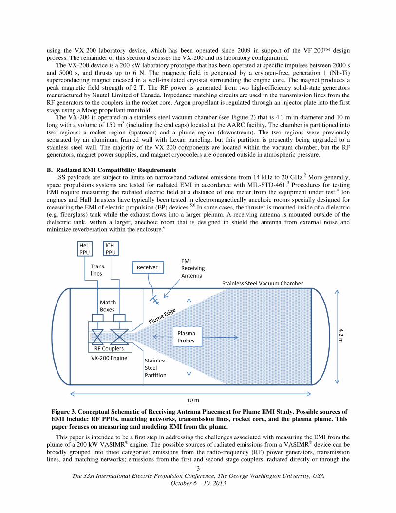
This paper is intended to be a first step in addressing the challenges associated with measuring the EMI from the
plume of a 200 kW VASIMR®
engine. The possible sources of radiated emissions from a VASIMR® device can be
broadly grouped into three categories: emissions from the radio-frequency (RF) power generators, transmission
lines, and matching networks; emissions from the first and second stage couplers, radiated directly or through the
Figure 3. Conceptual Schematic of Receiving Antenna Placement for Plume EMI Study. Possible sources of
EMI include: RF PPUs, matching networks, transmission lines, rocket core, and the plasma plume. This
paper focuses on measuring and modeling EMI from the plume.
The 33st International Electric Propulsion Conference, The George Washington University, USA
October 6 – 10, 2013
4
plasma; and emissions generated from plasma instabilities in the exhaust plume of the rocket. The strategy for
measuring the EMI from each of these sources is as follows.
The VX-200 RF generators currently operate outside of the vacuum chamber. They will be tested for EMI in the
laboratory in accordance with the “open field site” provision of the EMI testing requirements4, although the flight
generators will eventually need to be tested as part of the complete VF-200™ engine assembly. The first and second
stage couplers are integral to the VX-200 rocket core, which must be tested inside the vacuum chamber. The
chamber in this case will serve as an RF enclosure. Receiving antennas will be placed within the upstream section of
the vacuum chamber to measure the EMI propagating radially outward or upstream from the rocket core.
A typical EMI study of an EP device would involve only the testing in the preceding paragraph. In addition to
these tests we intend to study waves that are transmitted through the exhaust plume, being directly propagated from
the couplers or generated by instabilities in the plume. Receiving antenna measurements will be made in the
downstream section of the vacuum chamber, treating the plasma as a transmitter. The remainder of this paper will
discuss only the EMI from the plasma plume. Figure 3 shows the general plume EMI testing arrangement in the
chamber, along with the other potential sources of EMI. In previous studies, the plume-vacuum boundary has been
defined as the
The AARC vacuum facility may need to be modified to meet the requirements for EMI testing.4 To limit
reverberation during receiving antenna measurements, we may have to temporarily install electromagnetic absorbent
material on the interior walls of the vacuum chamber. Since the AARC chamber is large enough to study the
expansion of the plasma plume into vacuum7, we expect that much of the relevant plasma wave dynamics will be
present in this laboratory study. Even if the chamber could be made perfectly anechoic, however, the waves
propagating through the plasma plume could still be affected by the presence of the conducting walls. For this
reason, we will use theoretical estimates and numerical simulation, in addition to the traditional antenna
measurements, to study the electromagnetic emissions from the plume.
II. Plume EMI Study Plan
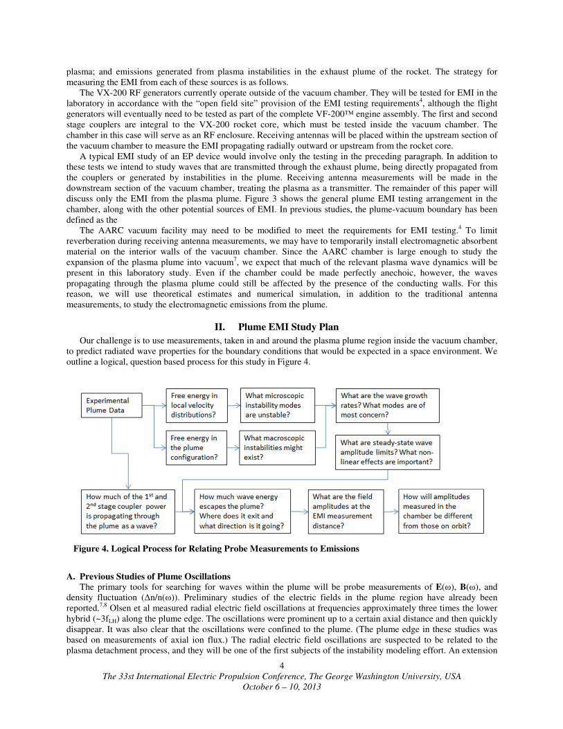
Our challenge is to use measurements, taken in and around the plasma plume region inside the vacuum chamber,
to predict radiated wave properties for the boundary conditions that would be expected in a space environment. We
outline a logical, question based process for this study in Figure 4.
A. Previous Studies of Plume Oscillations
The primary tools for searching for waves within the plume will be probe measurements of E(ω), B(ω), and
density fluctuation (∆n/n(ω)). Preliminary studies of the electric fields in the plume region have already been
reported.7,8
Olsen et al measured radial electric field oscillations at frequencies approximately three times the lower
hybrid (~3fLH) along the plume edge. The oscillations were prominent up to a certain axial distance and then quickly
disappear. It was also clear that the oscillations were confined to the plume. (The plume edge in these studies was
based on measurements of axial ion flux.) The radial electric field oscillations are suspected to be related to the
plasma detachment process, and they will be one of the first subjects of the instability modeling effort. An extension
Figure 4. Logical Process for Relating Probe Measurements to Emissions

The 33st International Electric Propulsion Conference, The George Washington University, USA
October 6 – 10, 2013
5
of these probe measurements is planned, wherein the axial and radial components of the electric and magnetic fields
will be measured across the frequency spectrum of concern for EMI.
B. Propagation of the Coupler Drive Frequencies The VX-200 coupler drive frequencies will be the first subjects of our EMI testing, since they are an
intentionally generated source of electromagnetic energy. The first stage of the rocket core uses a commercial
standard frequency in the FM band, while the second stage drive frequency is in the AM band. AARC routinely
employs a full-wave simulation method to model the propagation and absorption of the input RF energy into the
plasma within the rocket core. As a first step in the EMI modeling process, we will extend the domain of the full-
wave simulation further into the plume, providing a first approximation of the injected RF amplitudes within the
plume. These amplitudes will be compared to measurements of the vector electric and magnetic fields within the
plume. Depending on the results of this comparison, we may have to modify the full-wave code to more closely
model the plasma in the plume.
C. Modeling the Plasma Exhaust Plume as a Source of EMI
Figure 5 shows the natural frequencies in the probe measurement region inside the plasma plume. The
frequencies in this region span at least six orders of magnitude, all of which lie within the range of concern for EMI
compatibility. The plasma transitions from a high field in the rocket core, through several orders of magnitude in
field strength, to unmagnetized ballistic trajectories downstream.7,8
These transitions complicate the choice for
modeling assumptions, and make it difficult to simulate long sections of the plume flow with one numerical
algorithm.
One can also infer that, as the magnetic field strength and plasma density decrease as one looks downstream of
the probe measurement region, the natural oscillations will occur at lower frequencies. We hope to conservatively
estimate the emissions from the full extent of the laboratory plume, including the regions that are inaccessible to
both plasma probes and receivers mounted outside the plume.
There are two major classes of instability: macroscopic instabilities that are driven by the free energy of an
unstable configuration and microscopic instabilities that tap the free energy of non-equilibrium distribution
functions. The former will be investigated addressed by a combination of analytic energy principle estimates and
two-fluid simulations. Addressing the latter will require a method that uses plasma probe data as input. The
microinstabilities generally occur at frequencies greater than the ion cyclotron and can range over all natural
frequencies of the plasma, while macroinstabilities generally occur at lower frequencies.9
A review of the relevant
literature indicates that
instability modeling is nearly
always motivated by the direct
observation of specific
instabilities or by some
experimental evidence of their
existence. Many instability
phenomena are, in fact, named
for the way in which they
become manifest in experimental
data, e.g. “flute” instability,
“sausage” instability, “fire hose”
instability. Similarly, we are
concerned with that contribute to
EMI observations. Our aim is to
perform an investigation over a
broad frequency range to
determine what modes, if any,
cause significant EMI into the
vacuum region surrounding the plume. This instability investigation will help guide direct measurements of EMI in
the vacuum chamber. The investigation will also help to determine what emissions measured in the vacuum chamber
will be important for meeting electromagnetic compatibility requirements. There are too many possible modes,
however, to model them all simultaneously and accurately. Our modeling efforts must therefore be guided by
experimental observations of instability, by emissions in the vacuum, or by theoretical arguments as to what
Figure 5. Natural frequencies along the plume axis in the probe
measurement region: fci (ion cyclotron), fLH (lower hybrid), fpi (ion
plasma), fce (electron cyclotron), fpe (electron plasma), fUH (upper hybrid)

The 33st International Electric Propulsion Conference, The George Washington University, USA
October 6 – 10, 2013
6
instabilities might exist in the plume, given the observed configuration. In Figure 6, we outline the practical method
by which we will investigate the possible instabilities in the plasma plume.
D. Macroscopic Instabilities Our investigation of macroscopic instabilities will begin with analytical calculations of growth rates using
published formulae. We will use experimental data to model the plume configuration.
Two fluid simulations will be performed based on the results of analytical investigation. We anticipate that the
treatment of ions and electrons as separate fluids will be required, especially in downstream sections of the plume
where the electrons remain magnetized but the ions are beginning to detach from the magnetic nozzle. Additionally,
it is only the ions that are heated in the second stage of the VASIMR® engine core, which further motivates the
separate treatment of the ions and electrons.
A VASIMR® engine exhaust was previously simulated using the NIMROD code with the goal of studying the
plasma detachment process.10
The NIMROD code was designed to study long-wavelength, low-frequency, nonlinear
phenomena in toroidal plasmas.11
The previously reported study was only preliminary, treating the ions and
electrons as a single fluid and using a generalized Ohm’s Law and the adiabatic equation of state. The results were
somewhat inconsistent with experimental observations. The code does have a provision for treating the electrons as
a separate fluid with an electron temperature10
.
E. Microscopic Instabilities: Dispersion Analysis We will determine the availability and distribution of free energy in the plasma by measuring the ion and
electron velocity space distribution functions, and the cold plasma density and temperature, on a 2-d grid spanning
the exhaust chamber equatorial plane. The velocity distributions will be measured by retarding potential analyzers,
ideally with articulating heads, so that the pitch angle distribution can also be measured. The velocity distribution,
along with the plasma density and the cold plasma temperature, will serve as input to a numerical dispersion solving
algorithm. This method will produce growth rates for all 3 normal modes as a function of frequency.
One attractive numerical algorithm is that of Matsuda and Smith.12
The method solves the dispersion relation
(Eq.) for a uniform, infinite plasma in a uniform magnetic field, �� � ���̂. The code allows for input of an arbitrary
Figure 6. General Plume EMI Study Methodology

The 33st International Electric Propulsion Conference, The George Washington University, USA
October 6 – 10, 2013
7
velocity distribution, given by values on a two-dimensional velocity space grid, or by analytic functions. This
method would preclude without the need to fit the RPA data to a sum of model distributions.12
We would execute
this algorithm at each point in our 2D experimental measurement grid, thereby creating a map of growth rate vs.
wave number for an arbitrary propagation angle at each point in the plume.
�1 − � � � � � + �
� �� + 4��� �� � 0
(1)
Here, � � ���� + �∥�̂ is the wave vector, ω is the complex frequency, c is the speed of light, I is the unit dyadic,
and σ is the conductivity tensor.
Regardless of the algorithm used, we may have to limit the computation space by preliminary analytic estimates
as to which modes are the most likely to be unstable, and by using thermodynamic estimates of the amount of free
energy in the distribution functions to direct our computational attention to specific, limited regions of the plume.
F. Nonlinear Wave Amplitude Limits within the Plume
Since the VF-200™ firings will be long compared to most wave mode growth times, the non-linear excitation
limit of the amplitude of the dominant wave modes and the damping mechanisms of those modes in other regions of
the plume are of interest. To this end, we will attempt to corroborate results of the dispersion analysis and of the
macroscopic stability analysis with experimental measurements of the vector electric field, magnetic field, and
plasma density fluctuations; i.e. if the models indicate a large growth rate in a particular region of configuration and
frequency space, we should expect to measure a significant wave amplitude. Ideally, we could use the probe
measurements as an exclusive determination of the wave amplitudes inside the plume. However, there are regions of
the plume that are inaccessible to probes (see Figure 2). Additionally, we desire to model a nonlinear limit of the
dominant wave amplitudes consistently with our equilibrium plasma parameters. Comparison of modeled
amplitudes with measured amplitudes will be important for checking the accuracy of our instability models.
The most general way to numerically simulate the nonlinear dynamics of plasma waves is to use an
electromagnetic particle-in-cell simulation. The particle positions and velocities are advanced in time by Newton’s
Second Law, while the fields and charge quantities are stored on a grid and advanced using finite differencing of
Maxwell’s equations. Particle codes are computer resource intensive and are typically tailored to a specific problem
so that only relevant physical space and time scales are resolved.
G. Wave Propagation through the Plasma and Emission at the Plasma-Vacuum Interface
To model wave propagation through the plume we will use either a ray tracing algorithm or a full wave
simulation. The choice will depend on the particular mode being investigated and its expected behavior at the edge
of the plume. Ray tracing methods have the advantage of being computationally less intense, although they do not
treat mode conversion as naturally as full-wave codes. To model the linear growth or damping of the wave, the ray
tracing calculations must use complex wave numbers or be coupled with Fokker Planck codes to model the
interaction with the plasma distribution function. The latter technique is well documented as a method to model
radio frequency heating in fusion energy application.13
Since we presume to have measured the distribution
functions that coexist with an identified wave mode, our ray tracing calculations must take place in complex space
so that the growth or damping of the wave can be modeled consistently.
One possible ray-tracing technique is R. Horne’s HOTRAY code, which models wave propagation and growth in
a hot, anisotropic plasma.14
This code was developed to study the generation of radiation in the terrestrial
magnetosphere. The algorithm uses the geometric optics method, and therefore assumes that plasma parameters do
not change significantly along one wavelength. HOTRAY determines the ray path by integrating Hamilton’s
equations (Eqs. (1) and (2)) with the condition that the hot plasma dispersion relation must be satisfied.
���� � − !
� ! �"
(2)
���� �
! �
! �"
(3)
!#�, �, �% � 0
(4)

The 33st International Electric Propulsion Conference, The George Washington University, USA
October 6 – 10, 2013
8
& � '�( ∙ ∆� (5)
Here, x is the position vector of a point along the ray path, ω is the angular wave frequency, k is the wave vector,
D is the dispersion relation, and Γ is the path-integrated growth rate. The algorithm uses real ω and k to integrate
Eqs. (2) and (3), but the complex wave number (k+ki) is found from solving the dispersion relation at each new
point in space. The growth rate can then be calculated by Eq. (5). The imaginary part of k, is assumed to be small
compared to the real part, so the method is only valid for weakly damped or growing waves.
For regions of physical or frequency space for which the ray-tracing assumptions are not valid, the next choice of
simulation technique is full-wave modeling. Full-wave algorithms solve for the fields throughout the entire plasma
at each time step, and some algorithms can model arbitrarily high harmonics of the cyclotron frequency15
.
Additionally, with sufficient resolution, full wave simulations can accurately model wave mode conversion
processes. At the vacuum interface, an electrostatic mode will need to couple to an electromagnetic mode in order
for the wave energy to leave the plasma (for example, see 16
).
The limits of full-wave algorithm are encountered when the assumptions that kρ<<1 or ρ/L<<1 become invalid.
Here, ρ is the gyroradius and k is the wave number. AORSA is one code that eliminates the concern about kρ,
because it does not make an expansion involving this quantity. The ρ/L assumption must still be satisfied however,
which can become problematic for frequencies near fci in regions where the ion gyroradius is becoming large
compared to spatial scale lengths.
H. PIC as an Alternative
In principle, particle-in-cell simulation could be used as a substitute for any of the numerical procedures listed
above. Given sufficient resolution, particle codes can model instability growth, nonlinear wave interactions and
wave propagation. However, because they require so much computer time and self-consistent initialization of
distribution functions, we will use particle simulations only if justified by experimental observation. Particle
simulations might be used to evaluate approximations for selected instabilities or to benchmark the less explicit
methods of our instability analysis.
I. Receiving Antenna Measurements
We will measure the vacuum radiated fields in the downstream section of the vacuum chamber. The receiving
antenna will be placed in a region outside of the plasma plume, and measurements will be made to as many
specifications of MIL-STD-461 as practical.
The steel walls of the vacuum chamber will also act as a reverberating chamber where the EMI will excite
distinct chamber modes which may obscure the actual EMI emissions. To prevent from obscuring radiated
emissions levels, MIL-STD-461 requires that radio frequency absorbers be installed on all walls surrounding the
equipment under test. Such an installation in our vacuum chamber would be very expensive and time consuming.
The absorbing material would likely not be suited to long term operation in a plasma discharge, and would therefore
need to be removed after EMI testing was complete.
Figure 7. Chamber Set Up as a Reverberation Chamber with Mode Stirrers, a Possible
Alternative to Using RF Absorbing Material

The 33st International Electric Propulsion Conference, The George Washington University, USA
October 6 – 10, 2013
9
A possible alternative to the use of RF absorbers is mode-stirring. Methods for measuring EMI in a reverberating
chamber have been theorized for rectangular chambers.17,18
The methods use multimode resonance mixing whereby
mode stirring devices continuously vary the geometry inside the chamber so that resonant modes close to each other
are smoothly coupled. Mechanical mixing vanes were first suggested as the means for mixing.18
However, more
recently electronic mode stirring has been developed.19
Mechanical mode mixing has been shown to produce a
uniform field in the test chamber away from the chamber walls, test article and other boundaries.20
Figure 7 shows a
possible arrangement of mode stirrers in the AARC chamber.
A possible reverberating chamber testing procedure could be as follows.18
First, the test article is activated and
run through a test cycle. Next, a calibrated signal generator attached to an antenna with known characteristics is
used. The signal is adjusted until it matches the signal received during testing. The signal from the calibrated
antenna is then related to the signal measured from the test article. Recommendations for the use of a reverberating
chamber are published in MIL-STD-461 (latest revision), although the standard allows the use of reverberating
chambers only for testing of susceptibility, not for emissions. The reverberation chamber method is also limited to a
minimum frequency, based on the size of the chamber. This low frequency limit is based on requiring a certain
density of modes in the chamber.3
J. Extending the Study to the VF-200™
The testing described above will involve the VX-200 prototype, which is a single-core thruster. The VF-200™
flight model, on the other hand, will utilize a quadrupole magnet configuration with side-by-side thrusters. The VF-
200™ plume may potentially produce EMI that is not present in the dipole configuration of the VX-200 prototypes.
Modeling the oppositely polarized side-by-side thrusters will be addressed in a subsequent study. Estimates of EMI
from the plasma plume will eventually be compared to on-orbit measurements from the Aurora Plasma Diagnostics
Platform (APDP), which will contain a suite of diagnostic probes designed to study a wide variety of physics in the
VF-200™ plume.21
To predict the on-orbit emissions, we will attempt to modify the boundary conditions of any
successful simulations. For instance, the boundary of the full-wave model could be altered so that the outgoing
waves are perfectly absorbed.
References
1
E. A. Bering III, F. R. Chang Diaz, J. P. Squire, T. W. Glover, M. D. Carter, G. E. McCaskill, B. W. Longmier,
M. S. Brukardt, W. J. Chancery and V. T. Jacobson, "Observations of Single-Pass Ion Cyclotron Heating in a
Trans-Sonic Flowing Plasma," Physics of Plasmas, vol. 17, no. 4, 2010. 2
International Space Station Program, "SSP 30237 Revision T: Space Station Electromagnetic Emission and
Susceptibility Requirements," 2010. 3
Department of Defense, MIL-STD-461F Requirements for the Control of Electromagnetic Interference
Characteristics of Subsystems and Equipment, 2007. 4
International Space Station Program, "SSP 30238 Revision E: Space Station Electromagnetic Techniques," 2002. 5
K. Nishiyama, Y. Shimizu, I. Funaki, H. Kuninaka and K. Toki, "Measurements of the Electromagnetic Emissions
from the MUSES-C Ion Engine System," International Electric Propulsion Conference, 2001. 6
E. J. Beiting, X. L. Eapen and J. E. Pollard, "Electromagnetic Emissions from PPS 1350 Hall Thruster,"
International Electric Propulsion Conference, 2009. 7
C. S. Olsen, "Experimental Characterization of Plasma Detachment from Magnetic Nozzles," Ph. D. Dissertation,
Physics and Astronomy Department, Rice University, Houston, TX, 2013. 8
C. S. Olsen, M. G. Ballenger, M. D. Carter, F. R. Chiang-Diaz, M. Giambusso, T. W. Glover, A. V. Ilin, J. P.
Squire, B. W. Longmier and E. A. Bering III, "An Experimental Study of Plasma Detachment from a Magnetic
Nozzle in the Plume of the VASIMR Engine," in International Electric Propulsion Conference, Washington, DC,
2013. 9
D. B. Melrose, Instabilities in Space and Laboratory Plasmas, Cambridge, 1986. 10
A. G. Tarditi and J. V. Shebalin, "Magnetic Nozzle Plasma Exhaust Simulation for the VASIMR Advanced
Propulsion Concept," in International Electric Propulsion Conference, 2003.

The 33st International Electric Propulsion Conference, The George Washington University, USA
October 6 – 10, 2013
10
11 A. H. Glasser, C. R. Sovinec, R. A. Nebel, T. A. Gianakon, S. J. Plimpton, M. S. Chu, D. D. Schnak and the
NIMROD Team, "The NIMROD Code: A New Approach to Numerical Plasma Physics," Plasma Physics and
Controlled Fusion, vol. 41, no. 3A, pp. A747-A755, 1999. 12
Y. Matsuda and G. R. Smith, "A Microinstability Code for a Uniform Magnetized Plasma with an Arbitrary
Distribution Function," Journal of Computational Physics, vol. 100, pp. 229-235, 1992. 13
P. T. Bonoli and R. C. Englade, "Simulation Model for Lower Hybrid Current Drive," Physics of Fluids, vol. 29,
no. 9, 1986. 14
R. B. Horne, "Path-Integrated Growth of Electrostatic Waves: The Generation of Terrestrial Myriametric
Radiation," Journal of Geophysical Research: Space Physics, vol. 94, no. A7, pp. 8895-8909, 1989. 15
E. F. Jaeger, L. A. Berry, and D. B. Batchelor, ''Full-Wave Calculation of Sheared Poloidal Flow Driven by High-
Harmonic Ion Bernstein Waves in Tokamak Plasmas," Physics of Plasmas, vol. 7, no. 8, p. 3319, 2000. 16
G. Taylor, P. C. Efthimion, B. Jones, B. P. LeBlanc, R. Maingi, "Enhancement of Mode-Converted Electron
Bernstein Wave Emission during National Spherical Torus Experiment H-mode Plasmas," Physics of Plasmas,
vol. 9, no. 1, p.167, 2002. 17
B. H. Liu, D. C. Chang and M. T. Ma, "Design Consideration of Reverberating Chambers for Electromagnetic
Interference Measurements," in IEEE International Symposium on EMC, 1983. 18
V. P. Kodali, Engineering Electromagnetic Compatibility, 2nd
ed., IEEE Press, 2001. 19
D. A. Hill, "Electronic Mode Stirring for Reverberation Chambers," in IEEE Transactions on Electromagnetic
Compatibility, 1994. 20
H. Spiegelaar and E. Vanderheyden, "The Mode Stirred Chamber-A Cost Effective EMC Testing Alternative," in
IEEE International Symposium on EMC, 1995. 21
E. A. Bering III, S. K. Antiochos, B. J. Thompson, M. D. Carter, L. Cassady, B. Longmier, J. P. Squire, C. R.
Devore, J. Shebalin, J. P. McFadden and D. M. Smith, "ISS Space Plasma Laboratory: An Orbital Solar and
Heliospheric Physics Simulation Facility," 51st AIAA Aerospace Sciences Meeting including the New Horizons
Forum and Aerospace Exposition, 2013.
Related Documents