A Novel System for Advanced Driver Assistance Systems Mohammadreza Sarshar Computer Engineering Department Azad University, Karaj Branch Karaj, Iran [email protected] Mahdi Rezaei (Ghahroudi) Computer Engineering Department Azad University, Qazvin Branch Qazvin, Iran [email protected] Abstract—The complexity of the driving task and uncertainty of the driving environment make driving as a very dangerous task. Various investigations show that speeding and lane departure are two main causes of road accidents. These would be more challenging in curvy roads. The paper describes a multi sensor systematic framework to solve the mentioned problem and a novel deployment for a network of multi-sensors is introduced. Some of implemented sensors are curve sensors, distance sensor, vision sensor and weather sensors as well as an indoor camera to control awareness of driver. To perform this work, we are using the Matlab fuzzy logic toolkit, which is a simple and flexible tool to design fuzzy inference systems. Keywords- Advanced Driver Assistance Systems; Driver Monitoring; Fuzzy Data Fusion; Sensor Network I. INTRODUCTION Safe driving is a major concern of societies all over the world. Thousands of people are killed, or seriously injured due to car accidents each year. According to NHTSA (National Highway Traffic Safety Administration) recent studies, speeding is one of the most prevalent factors contributing to traffic crashes. The economic cost to society of speeding- related crashes is estimated by NHTSA to be $40.4 billion per year. In 2008, speeding was a contributing factor in 31 percent of all fatal crashes, and 11,674 lives were lost in speeding- related crashes (figure 1 shows number of fatal crashes due to speeding in united states). That is because speeding reduces a driver’s ability to steer safely around curves or objects in the roadway, extends the distance necessary to stop a vehicle, and increases the distance a vehicle travels while the driver reacts to a dangerous situation. Therefore, it is essential to develop a safety system for redundant speeding prevention especially on curvy roads. Nearly 4 out of every 10 fatal motor vehicle crashes—over 16,000 a year—involve a single vehicle leaving its lane and/or the roadway, and there are more than twice as many fatal lane- departure crashes on rural roads than on urban roads. Some 42 percent of fatal lane departure crashes occur on curves (50 percent in rural areas), and the life-threatening events most likely to occur are rollovers (42 percent) and collisions with trees (25 percent). Based on NHTSA report on 2006, 25082 lane departure fatalities occurred. Figure 1 represents total lane departure fatalities occurred in USA. Figure 1. Lane departure fatality in USA A multisensory system has been proposed in this paper to solve both problems- Lane and speed control systems. II. RELATED WORK Although the initial developments in the field of Driver Assistance Systems (DAS) intended to increase the drivers’ comfort, starting with park assisting systems, cruise control and then Automatic Cruise Control (ACC), Recent Research for ADAS is being aimed to increasing the level of the safety for both driver and pedestrians [1]. A. Driver assistant systems Driver assistance systems aim at increasing the comfort and safety of traffic participants by sensing the environment, analyzing the situation and signaling relevant information to the driver. In general, this type of systems comprises one or more environment sensors such as RADAR, camera or LASER and a control algorithm that informs the driver or even autonomously influences the vehicle by means of the throttle and/or brakes. 978-1-4244-5883-7/10/$26.00 ©2010 IEEE

Welcome message from author
This document is posted to help you gain knowledge. Please leave a comment to let me know what you think about it! Share it to your friends and learn new things together.
Transcript

A Novel System for Advanced Driver Assistance Systems
Mohammadreza Sarshar Computer Engineering Department
Azad University, Karaj Branch Karaj, Iran
Mahdi Rezaei (Ghahroudi) Computer Engineering Department
Azad University, Qazvin Branch Qazvin, Iran
Abstract—The complexity of the driving task and uncertainty of the driving environment make driving as a very dangerous task. Various investigations show that speeding and lane departure are two main causes of road accidents. These would be more challenging in curvy roads. The paper describes a multi sensor systematic framework to solve the mentioned problem and a novel deployment for a network of multi-sensors is introduced. Some of implemented sensors are curve sensors, distance sensor, vision sensor and weather sensors as well as an indoor camera to control awareness of driver. To perform this work, we are using the Matlab fuzzy logic toolkit, which is a simple and flexible tool to design fuzzy inference systems.
Keywords- Advanced Driver Assistance Systems; Driver Monitoring; Fuzzy Data Fusion; Sensor Network
I. INTRODUCTION Safe driving is a major concern of societies all over the
world. Thousands of people are killed, or seriously injured due to car accidents each year. According to NHTSA (National Highway Traffic Safety Administration) recent studies, speeding is one of the most prevalent factors contributing to traffic crashes. The economic cost to society of speeding-related crashes is estimated by NHTSA to be $40.4 billion per year. In 2008, speeding was a contributing factor in 31 percent of all fatal crashes, and 11,674 lives were lost in speeding-related crashes (figure 1 shows number of fatal crashes due to speeding in united states). That is because speeding reduces a driver’s ability to steer safely around curves or objects in the roadway, extends the distance necessary to stop a vehicle, and increases the distance a vehicle travels while the driver reacts to a dangerous situation. Therefore, it is essential to develop a safety system for redundant speeding prevention especially on curvy roads.
Nearly 4 out of every 10 fatal motor vehicle crashes—over
16,000 a year—involve a single vehicle leaving its lane and/or the roadway, and there are more than twice as many fatal lane-departure crashes on rural roads than on urban roads. Some 42 percent of fatal lane departure crashes occur on curves (50 percent in rural areas), and the life-threatening events most likely to occur are rollovers (42 percent) and collisions with trees (25 percent). Based on NHTSA report on 2006, 25082
lane departure fatalities occurred. Figure 1 represents total lane departure fatalities occurred in USA.
Figure 1. Lane departure fatality in USA
A multisensory system has been proposed in this paper to
solve both problems- Lane and speed control systems.
II. RELATED WORK Although the initial developments in the field of Driver
Assistance Systems (DAS) intended to increase the drivers’ comfort, starting with park assisting systems, cruise control and then Automatic Cruise Control (ACC), Recent Research for ADAS is being aimed to increasing the level of the safety for both driver and pedestrians [1].
A. Driver assistant systems Driver assistance systems aim at increasing the comfort
and safety of traffic participants by sensing the environment, analyzing the situation and signaling relevant information to the driver. In general, this type of systems comprises one or more environment sensors such as RADAR, camera or LASER and a control algorithm that informs the driver or even autonomously influences the vehicle by means of the throttle and/or brakes.
978-1-4244-5883-7/10/$26.00 ©2010 IEEE
The first developments in the field of ADAS aimed to increase driver comfort, starting with cruise control and now resulting in ACC. In the last few years however, ADAS research is directed towards increasing the safety of the driver and the passengers [2].
The behavior of a vehicle is controlled according to the information obtained from the environment by sensors and according to knowledge (e.g., the state of the vehicle like steering angle and velocity, yaw rate and global information e.g., evaluated GPS-data).
This information has to be interpreted according to position, movement direction and relative velocity of relevant objects. Relevant objects are characterized by the grade of influence they have on the vehicle and by the actual task. These objects can be other road users as well as traffic signs, elements of the landscape or the lane itself.
B. Curvy road assistance There are many circumstances where we have to consider
the safety of a driver. For example, we often face dangerous situations on curvy roads such as unreasonable overtaking or speeding, where a vehicle cannot be seen by other vehicles traveling from the opposite direction etc. For the case of such situations, there are several systems suggested to reduce the danger of unexpected accidents.
One is collision warning system for the convergence of telematics and wireless sensor networks technologies [3]. It can satisfy the requirements of 1) event driven operation, 2) deployment considering road structure, and 3) routing schemes considering data characteristics. Another system is Advanced Driver Speed Assistance in Curves (ADSAC) [4].
There are also some methods of detecting road edges in millimeter wave radar images [5],all of which are based on deformable template priors and random field likelihoods . The first method is formulated in a Bayesian setting and employs an adaptive MAP estimate. The second method is a modification of the first, using a novel weighting scheme. The third method is based on a three-region indicator matrix which is used to impose the non-linear constraints implicit on road geometry via addition of a sum of quasi-quadratic matrix forms to the lognormal likelihood.
In this paper we present a system using fuzzy linguistic variables to control speed, using data provided by sensors and a drowsiness warning system which is based on the fuzzy logic images analysis [6].
C. Driver’s Vigilance Detection One of the most popular methods for driver’s fatigue
detection is eyelid assessment based on features extracted by a single camera and eye closure rate. M. H. Sigari has provided a hypo-vigilance detection system based on eyelid behavior and eye-region processing [7]. He used a combination method to measure eye-lid distance and eye closure rate. This method suffers from a high degree of computational complexity and need to be improved.
L. Fletcher et al. offered a method of observation for driver’s action and observation to track eye gaze and head
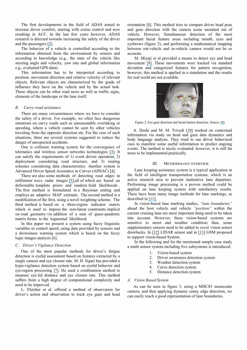
orientation [8]. This method tries to compare driver head pose and gaze direction with the camera scene mounted out of vehicle. However, Simultaneous detection of the most important facial feature areas including mouth, eyes and eyebrows (figure 2), and performing a mathematical mapping between out-vehicle and in-vehicle camera would not be so accurate.
M. Miyaji et al provided a means to detect eye and head movement [9]. These movements were tracked via standard deviation and categorized features for pattern recognition; however, this method is applied in a simulation and the results for real world are not available.
Figure 2. Eye gaze direction and facial feature detection. Source: [8]
A. Doshi and M. M. Trivedi [10] worked on contextual information via study on head and gaze data dynamics and body language analysis. They tried to use driver behavioral cues to manifest some useful information to predict ongoing events. The method is nicely evaluated; however, it is still far more to be implemented practically.
III. METHODOLOGY OVERVIEW Lane keeping assistance system is a typical application in
the field of intelligent transportation systems, which is an active research area to prevent inattentive lane departure. Performing image processing is a proven method could be applied on lane keeping system with satisfactory results. There have been many image methods for lane markings, as described in [11].
In vision-based lane marking studies, “lane boundaries” ahead the host vehicle and vehicle “position” within the current cruising lane are most important thing need to be taken into account. However, these vision-based systems are sensitive to street and weather condition; thus, some supplementary sensors need to be added to cover vision sensor drawbacks. In [12] LIDAR sensor and in [13] GSM proposed to support vision-based System.
In the following and for the mentioned sample case study a multi sensor system including five subsystems is introduced:
1. Vision-based system 2. Driver awareness detection system 3. Weather detection system 4. Curve detection system 5. Distance detection system
A. Vision Based System As can be seen in figure 3, using a MDCS3 monocular
camera, and then applying dynamic canny edge detection, we can easily reach a good representation of lane boundaries.
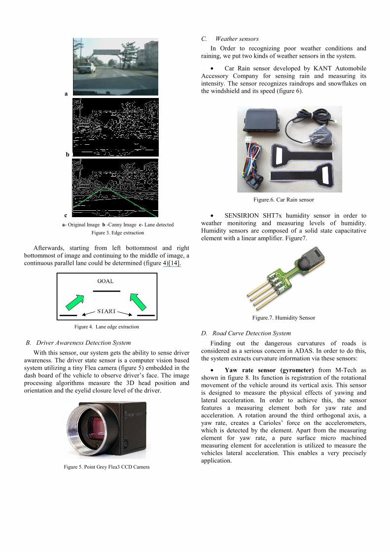
a
b
c
a- Original Image b -Canny Image c- Lane detected
Figure 3. Edge extraction
Afterwards, starting from left bottommost and right bottommost of image and continuing to the middle of image, a continuous parallel lane could be determined (figure 4)[14].
Figure 4. Lane edge extraction
B. Driver Awareness Detection System With this sensor, our system gets the ability to sense driver
awareness. The driver state sensor is a computer vision based system utilizing a tiny Flea camera (figure 5) embedded in the dash board of the vehicle to observe driver’s face. The image processing algorithms measure the 3D head position and orientation and the eyelid closure level of the driver.
Figure 5. Point Grey Flea3 CCD Camera
C. Weather sensors In Order to recognizing poor weather conditions and
raining, we put two kinds of weather sensors in the system.
• Car Rain sensor developed by KANT Automobile Accessory Company for sensing rain and measuring its intensity. The sensor recognizes raindrops and snowflakes on the windshield and its speed (figure 6).
Figure.6. Car Rain sensor
• SENSIRION SHT7x humidity sensor in order to
weather monitoring and measuring levels of humidity. Humidity sensors are composed of a solid state capacitative element with a linear amplifier. Figure7.
Figure.7. Humidity Sensor
D. Road Curve Detection System Finding out the dangerous curvatures of roads is
considered as a serious concern in ADAS. In order to do this, the system extracts curvature information via these sensors:
• Yaw rate sensor (gyrometer) from M-Tech as shown in figure 8. Its function is registration of the rotational movement of the vehicle around its vertical axis. This sensor is designed to measure the physical effects of yawing and lateral acceleration. In order to achieve this, the sensor features a measuring element both for yaw rate and acceleration. A rotation around the third orthogonal axis, a yaw rate, creates a Carioles’ force on the accelerometers, which is detected by the element. Apart from the measuring element for yaw rate, a pure surface micro machined measuring element for acceleration is utilized to measure the vehicles lateral acceleration. This enables a very precisely application.
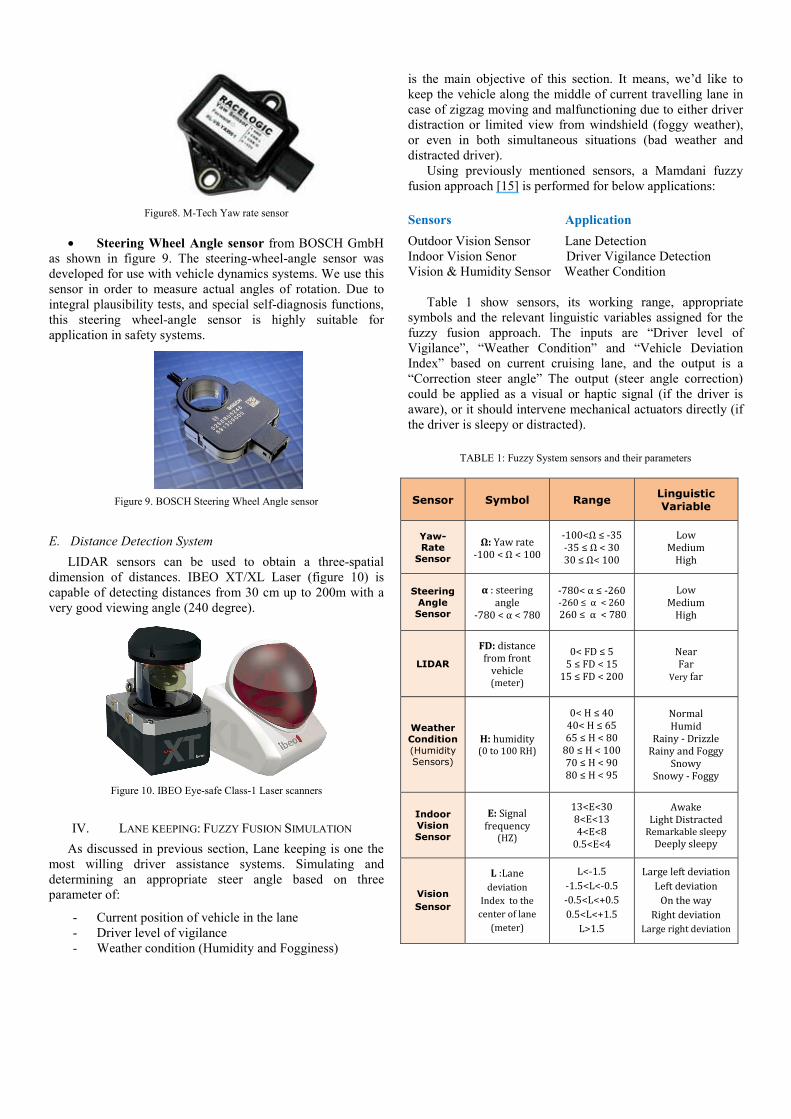
Figure8. M-Tech Yaw rate sensor
• Steering Wheel Angle sensor from BOSCH GmbH as shown in figure 9. The steering-wheel-angle sensor was developed for use with vehicle dynamics systems. We use this sensor in order to measure actual angles of rotation. Due to integral plausibility tests, and special self-diagnosis functions, this steering wheel-angle sensor is highly suitable for application in safety systems.
Figure 9. BOSCH Steering Wheel Angle sensor
E. Distance Detection System LIDAR sensors can be used to obtain a three-spatial
dimension of distances. IBEO XT/XL Laser (figure 10) is capable of detecting distances from 30 cm up to 200m with a very good viewing angle (240 degree).
Figure 10. IBEO Eye-safe Class-1 Laser scanners
IV. LANE KEEPING: FUZZY FUSION SIMULATION As discussed in previous section, Lane keeping is one the
most willing driver assistance systems. Simulating and determining an appropriate steer angle based on three parameter of:
- Current position of vehicle in the lane - Driver level of vigilance - Weather condition (Humidity and Fogginess)
is the main objective of this section. It means, we’d like to keep the vehicle along the middle of current travelling lane in case of zigzag moving and malfunctioning due to either driver distraction or limited view from windshield (foggy weather), or even in both simultaneous situations (bad weather and distracted driver).
Using previously mentioned sensors, a Mamdani fuzzy fusion approach [15] is performed for below applications: Sensors Application
Outdoor Vision Sensor Lane Detection Indoor Vision Senor Driver Vigilance Detection Vision & Humidity Sensor Weather Condition
Table 1 show sensors, its working range, appropriate symbols and the relevant linguistic variables assigned for the fuzzy fusion approach. The inputs are “Driver level of Vigilance”, “Weather Condition” and “Vehicle Deviation Index” based on current cruising lane, and the output is a “Correction steer angle” The output (steer angle correction) could be applied as a visual or haptic signal (if the driver is aware), or it should intervene mechanical actuators directly (if the driver is sleepy or distracted).
TABLE 1: Fuzzy System sensors and their parameters
Sensor Symbol Range Linguistic Variable
Yaw-Rate
Sensor
Ω: Yaw rate -100 < Ω < 100 -100<Ω ≤ -35 -35 ≤ Ω < 30 30 ≤ Ω< 100 Low Medium High
Steering Angle Sensor
α : steering angle -780 < α < 780 -780< α ≤ -260 -260 ≤ α < 260 260 ≤ α < 780 Low Medium High LIDAR
FD: distance from front vehicle (meter) 0< FD ≤ 5 5 ≤ FD < 15 15 ≤ FD < 200 Near Far Very far
Weather Condition (Humidity Sensors)
H: humidity (0 to 100 RH) 0< H ≤ 40 40< H ≤ 65 65 ≤ H < 80 80 ≤ H < 100 70 ≤ H < 90 80 ≤ H < 95
Normal Humid Rainy - Drizzle Rainy and Foggy Snowy Snowy - Foggy Indoor Vision Sensor
E: Signal frequency (HZ) 13<E<30 8<E<13 4<E<8 0.5<E<4
Awake Light Distracted Remarkable sleepy Deeply sleepy Vision Sensor
L :Lane deviation Index to the center of lane (meter) L<-1.5 -1.5<L<-0.5 -0.5<L<+0.5 0.5<L<+1.5 L>1.5
Large left deviation Left deviation On the way Right deviation Large right deviation
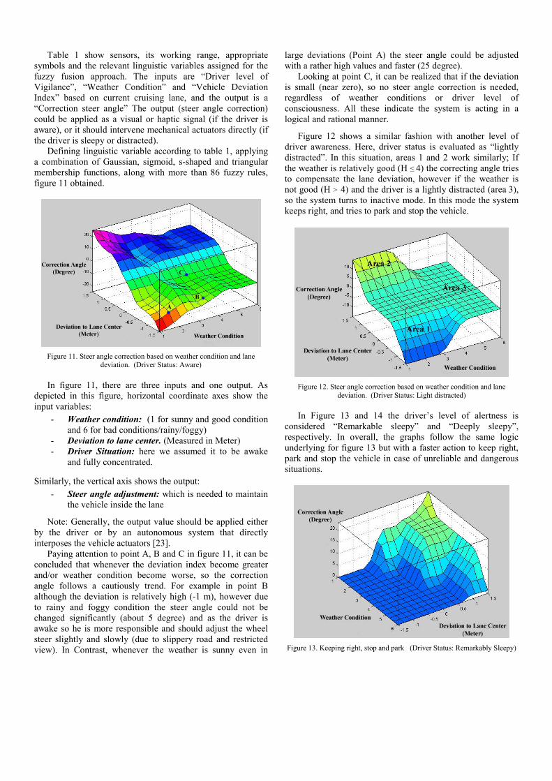
Table 1 show sensors, its working range, appropriate symbols and the relevant linguistic variables assigned for the fuzzy fusion approach. The inputs are “Driver level of Vigilance”, “Weather Condition” and “Vehicle Deviation Index” based on current cruising lane, and the output is a “Correction steer angle” The output (steer angle correction) could be applied as a visual or haptic signal (if the driver is aware), or it should intervene mechanical actuators directly (if the driver is sleepy or distracted).
Defining linguistic variable according to table 1, applying a combination of Gaussian, sigmoid, s-shaped and triangular membership functions, along with more than 86 fuzzy rules, figure 11 obtained.
Figure 11. Steer angle correction based on weather condition and lane deviation. (Driver Status: Aware)
In figure 11, there are three inputs and one output. As
depicted in this figure, horizontal coordinate axes show the input variables:
- Weather condition: (1 for sunny and good condition and 6 for bad conditions/rainy/foggy)
- Deviation to lane center. (Measured in Meter) - Driver Situation: here we assumed it to be awake
and fully concentrated.
Similarly, the vertical axis shows the output:
- Steer angle adjustment: which is needed to maintain the vehicle inside the lane
Note: Generally, the output value should be applied either by the driver or by an autonomous system that directly interposes the vehicle actuators [23].
Paying attention to point A, B and C in figure 11, it can be concluded that whenever the deviation index become greater and/or weather condition become worse, so the correction angle follows a cautiously trend. For example in point B although the deviation is relatively high (-1 m), however due to rainy and foggy condition the steer angle could not be changed significantly (about 5 degree) and as the driver is awake so he is more responsible and should adjust the wheel steer slightly and slowly (due to slippery road and restricted view). In Contrast, whenever the weather is sunny even in
large deviations (Point A) the steer angle could be adjusted with a rather high values and faster (25 degree).
Looking at point C, it can be realized that if the deviation is small (near zero), so no steer angle correction is needed, regardless of weather conditions or driver level of consciousness. All these indicate the system is acting in a logical and rational manner.
Figure 12 shows a similar fashion with another level of driver awareness. Here, driver status is evaluated as “lightly distracted”. In this situation, areas 1 and 2 work similarly; If the weather is relatively good (H ≤ 4) the correcting angle tries to compensate the lane deviation, however if the weather is not good (H > 4) and the driver is a lightly distracted (area 3), so the system turns to inactive mode. In this mode the system keeps right, and tries to park and stop the vehicle.
Figure 12. Steer angle correction based on weather condition and lane deviation. (Driver Status: Light distracted)
In Figure 13 and 14 the driver’s level of alertness is
considered “Remarkable sleepy” and “Deeply sleepy”, respectively. In overall, the graphs follow the same logic underlying for figure 13 but with a faster action to keep right, park and stop the vehicle in case of unreliable and dangerous situations.
Figure 13. Keeping right, stop and park (Driver Status: Remarkably Sleepy)
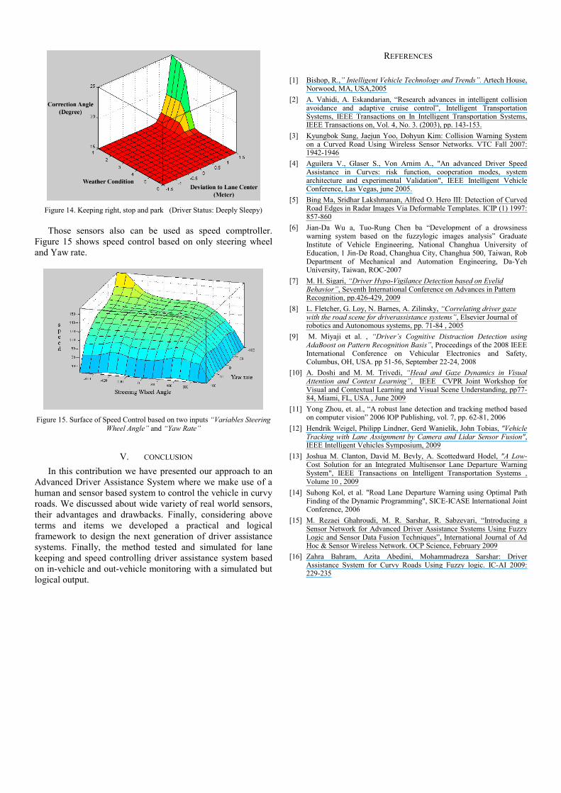
Figure 14. Keeping right, stop and park (Driver Status: Deeply Sleepy)
Those sensors also can be used as speed comptroller. Figure 15 shows speed control based on only steering wheel and Yaw rate.
Figure 15. Surface of Speed Control based on two inputs “Variables Steering Wheel Angle” and “Yaw Rate”
V. CONCLUSION In this contribution we have presented our approach to an
Advanced Driver Assistance System where we make use of a human and sensor based system to control the vehicle in curvy roads. We discussed about wide variety of real world sensors, their advantages and drawbacks. Finally, considering above terms and items we developed a practical and logical framework to design the next generation of driver assistance systems. Finally, the method tested and simulated for lane keeping and speed controlling driver assistance system based on in-vehicle and out-vehicle monitoring with a simulated but logical output.
REFERENCES
[1] Bishop, R.,” Intelligent Vehicle Technology and Trends”. Artech House, Norwood, MA, USA,2005
[2] A. Vahidi, A. Eskandarian, “Research advances in intelligent collision avoidance and adaptive cruise control”, Intelligent Transportation Systems, IEEE Transactions on In Intelligent Transportation Systems, IEEE Transactions on, Vol. 4, No. 3. (2003), pp. 143-153.
[3] Kyungbok Sung, Jaejun Yoo, Dohyun Kim: Collision Warning System on a Curved Road Using Wireless Sensor Networks. VTC Fall 2007: 1942-1946
[4] Aguilera V., Glaser S., Von Arnim A., "An advanced Driver Speed Assistance in Curves: risk function, cooperation modes, system architecture and experimental Validation", IEEE Intelligent Vehicle Conference, Las Vegas, june 2005.
[5] Bing Ma, Sridhar Lakshmanan, Alfred O. Hero III: Detection of Curved Road Edges in Radar Images Via Deformable Templates. ICIP (1) 1997: 857-860
[6] Jian-Da Wu a, Tuo-Rung Chen ba “Development of a drowsiness warning system based on the fuzzylogic images analysis” Graduate Institute of Vehicle Engineering, National Changhua University of Education, 1 Jin-De Road, Changhua City, Changhua 500, Taiwan, Rob Department of Mechanical and Automation Engineering, Da-Yeh University, Taiwan, ROC-2007
[7] M. H. Sigari, “Driver Hypo-Vigilance Detection based on Eyelid Behavior”, Seventh International Conference on Advances in Pattern Recognition, pp.426-429, 2009
[8] L. Fletcher, G. Loy, N. Barnes, A. Zilinsky, “Correlating driver gaze with the road scene for driverassistance systems”, Elsevier Journal of robotics and Autonomous systems, pp. 71-84 , 2005
[9] M. Miyaji et al. , “Driver’s Cognitive Distraction Detection using AdaBoost on Pattern Recognition Basis”, Proceedings of the 2008 IEEE International Conference on Vehicular Electronics and Safety, Columbus, OH, USA. pp 51-56, September 22-24, 2008
[10] A. Doshi and M. M. Trivedi, “Head and Gaze Dynamics in Visual Attention and Context Learning”, IEEE CVPR Joint Workshop for Visual and Contextual Learning and Visual Scene Understanding, pp77-84, Miami, FL, USA , June 2009
[11] Yong Zhou, et. al., “A robust lane detection and tracking method based on computer vision” 2006 IOP Publishing, vol. 7, pp. 62-81, 2006
[12] Hendrik Weigel, Philipp Lindner, Gerd Wanielik, John Tobias, "Vehicle Tracking with Lane Assignment by Camera and Lidar Sensor Fusion", IEEE Intelligent Vehicles Symposium, 2009
[13] Joshua M. Clanton, David M. Bevly, A. Scottedward Hodel, "A Low-Cost Solution for an Integrated Multisensor Lane Departure Warning System", IEEE Transactions on Intelligent Transportation Systems , Volume 10 , 2009
[14] Suhong Kol, et al. "Road Lane Departure Warning using Optimal Path Finding of the Dynamic Programming", SICE-ICASE International Joint Conference, 2006
[15] M. Rezaei Ghahroudi, M. R. Sarshar, R. Sabzevari, “Introducing a Sensor Network for Advanced Driver Assistance Systems Using Fuzzy Logic and Sensor Data Fusion Techniques”, International Journal of Ad Hoc & Sensor Wireless Network. OCP Science, February 2009
[16] Zahra Bahram, Azita Abedini, Mohammadreza Sarshar: Driver Assistance System for Curvy Roads Using Fuzzy logic. IC-AI 2009: 229-235
Related Documents