A Novel Hysteretic Model for Magnetorheological Fluid Dampers and Parameter Identification Using Particle Swarm Optimization N. M. Kwok * , Q. P. Ha, T. H. Nguyen, J. Li and B. Samali Faculty of Engineering, University of Technology, Sydney Broadway, NSW 2007, Australia Abstract Nonlinear hysteresis is a complicated phenomenon associated with magnetorheolog- ical (MR) fluid dampers. A new model for MR dampers is proposed in this paper. For this, computationally-tractable algebraic expressions are suggested here in con- trast to the commonly-used Bouc-Wen model, which involves internal dynamics represented by a nonlinear differential equation. In addition, the model parame- ters can be explicitly related to the hysteretic phenomenon. To identify the model parameters, a particle swarm optimization (PSO) algorithm is employed using ex- perimental force-velocity data obtained from various operating conditions. In our algorithm, it is possible to relax the need for a priori knowledge on the parameters and to reduce the algorithmic complexity. Here, the PSO algorithm is enhanced by introducing a termination criterion, based on the statistical hypothesis testing to guarantee a user-specified confidence level in stopping the algorithm. Parameter identification results are included to demonstrate the accuracy of the model and the effectiveness of the identification process. Key words: magnetorheological damper, modelling, particle swarm optimization. * Corresponding author. Email address: [email protected] (N. M. Kwok). Preprint submitted to Sensors and Actuators A, physical 3 March 2006

Welcome message from author
This document is posted to help you gain knowledge. Please leave a comment to let me know what you think about it! Share it to your friends and learn new things together.
Transcript

A Novel Hysteretic Model for
Magnetorheological Fluid Dampers and
Parameter Identification Using Particle
Swarm Optimization
N. M. Kwok ∗, Q. P. Ha, T. H. Nguyen, J. Li and B. Samali
Faculty of Engineering, University of Technology, SydneyBroadway, NSW 2007, Australia
Abstract
Nonlinear hysteresis is a complicated phenomenon associated with magnetorheolog-ical (MR) fluid dampers. A new model for MR dampers is proposed in this paper.For this, computationally-tractable algebraic expressions are suggested here in con-trast to the commonly-used Bouc-Wen model, which involves internal dynamicsrepresented by a nonlinear differential equation. In addition, the model parame-ters can be explicitly related to the hysteretic phenomenon. To identify the modelparameters, a particle swarm optimization (PSO) algorithm is employed using ex-perimental force-velocity data obtained from various operating conditions. In ouralgorithm, it is possible to relax the need for a priori knowledge on the parametersand to reduce the algorithmic complexity. Here, the PSO algorithm is enhancedby introducing a termination criterion, based on the statistical hypothesis testingto guarantee a user-specified confidence level in stopping the algorithm. Parameteridentification results are included to demonstrate the accuracy of the model and theeffectiveness of the identification process.
Key words: magnetorheological damper, modelling, particle swarm optimization.
∗ Corresponding author.Email address: [email protected] (N. M. Kwok).
Preprint submitted to Sensors and Actuators A, physical 3 March 2006

1 Introduction
Vibration suppression may be considered as a key component in the perfor-mance of civil engineering and mechanical structures for the safety and comfortof their occupants. In [1], a survey was conducted in the context of buildingcontrol where the magnetorheological (MR) damper as a semi-active devicewas introduced. The MR damper may be constructed in the cylinder-piston orpin-rotor form [2], which makes it widely applicable in various domains, e.g.,vehicle suspensions [3]. The actuation of MR dampers is governed by tinymagnetizable particles which are immersed in a carrier fluid and upon theapplication of an external magnetic field aligned in chain-like structures, see[4]. The alignment of particles changes the yield stress of the fluid and henceproduces a controllable damping force. The MR damper is an attractive can-didate in vibration suppression applications in which only a small amount ofenergizing power is required and the fluid characteristic is reversible in therange of milliseconds. The damper also features a fail-safe mode, acting as aconventional damper, and in case of hazardous situations as encountered inearthquakes where power supply may be interrupted.
Although the MR damper is promising in control applications, its major draw-back lies in the non-linear and hysteretic force-velocity response. Furthermore,the design of a controller generally requires a model of the actuator which maybe challenging in the case of employing the MR damper. The modelling of thehysteresis had been studied in [5] and [6] including the Bingham visco-plasticmodel, the Bouc-Wen model, the modified Bouc-Wen model and many others.These models range from simple dry-friction to complicated differential equa-tion representations. However, it is noted of a trade-off between the modelaccuracy and its complexity. From the control engineering point of view, non-linear differential equation based models may affect robustness of the controlsystem and hamper the feasible controller realization as in the case of MRdampers employed in the reduction of seismic response in buildings [7].
On the other end of the spectrum, polynomial based modelling of the MRdamper was attempted in [8] with a reduction in model complexity. A hyper-bolic function based curve-fitting model was proposed in [9] with satisfactoryresults. A black-box damper model was also applied in [10] as an alternative.Soft-computing techniques, fuzzy inference systems and neural networks werealso applied in modelling a MR damper; see [11] and [12], which representanother paradigm for a suitable approach towards an efficient model. Evo-lutionary computation methods, e.g., genetic algorithms [13], [14], have alsobeen widely applied in modelling and parameter identification applicationsand many others. In [15], the genetic algorithm (GA) was employed to iden-tify a mechatronic system of unknown structure. However, in addition to theimplementation complexity, the GA may found difficulties in convergence to
2

optimal parameters unless elitism [16] is explicitly incorporated in the algo-rithm. An identification procedure following this approach was reported in[17]. Moreover, a priori knowledge on the ranges of solutions may be requiredto accelerate the convergence rate.
A recently developed optimization technique, the particle swarm optimization(PSO), has been recognized as a promising candidate in applications to modelparameter identification when the identification is cast as an optimizationproblem. The PSO is based on the multi-agent or population based philosophy(the particles) which mimics the social interaction in bird flocks or schools offish, [18]. By incorporating the search experiences of individual agents, thePSO is effective in exploring the solution space in a relatively smaller numberof iterations, see [19]. In emulating bird flocks, particles are assigned withvelocities that lead their flight across the solution space. The best solutionsfound by an individual particle and by the whole population are memorizedand used in guiding further search flights. The best solution is reported at thesatisfaction of some termination criteria. Other applications of the PSO canbe found in the design of PID controllers [20] and electro-magnetics [21]. ThePSO convergence characteristic was analyzed in [22], where algorithm controlsettings were also proposed.
In this work, a novel model for the MR damper will be proposed. This modeluses a hyperbolic tangent function to represent the hysteretic loop togetherwith components obtained from conventional viscous damping and spring stiff-ness. This approach, as an attractive feature, maintains a relationship betweenthe damper parameters and physical force-velocity hysteretic phenomena andreduces the complexity from using a differential equation to describe the hys-teresis. The PSO is then applied to identify the model parameters using exper-imental force-velocity data obtained from a commercial MR damper. Here, toenhance the identification process, a statistical hypothesis testing procedureis adopted to determine the termination of the PSO. This procedure is ableto guarantee a user defined level of confidence on the quality of the identifiedparameters.
The rest of the paper is organized as follows. In Section 2, the MR damperis introduced and the commonly-used models are reviewed. The new model issuggested in Section 3 with a discussion of the model parameters. The PSO, asapplied in identifying the proposed model parameters, is presented in Section4 and its advantages are highlighted. Control settings for the algorithms aredetermined and a performance-enhanced criterion is also proposed. Results ofparameter identification are given in Section 5 together with some discussion.Finally, a conclusion is drawn in Section 6.
3

2 Magnetorheological Damper
2.1 Principle of Operation
The magnetorheological damper may be viewed as a conventional hydraulicdamper except that the contained fluid is allowed to change its yield stressupon the application of an external magnetic field. The structure of the damperis sketched in Fig. 1.
Fig. 1. MR damper structure.
Tiny magnetizable particles, e.g., carbonyl iron, are carried in non-magneticfluids such as silicon oil and are housed within a cylinder. In most applications,the damping force is generated in the flow-mode [23]. The yield of the MRfluid changes inversely to the temperature and a reduction in the damper forceresults with an increase in temperature. However, an appropriately designedcurrent controller can be applied to compensate for the change in the damperforce. This controller will also be employed for counteracting the long-termstability problem of the MR fluid. The MR damper used in this work is a RD-1005-3 model manufactured by the LORD Corporation. The damper has acompressed length of 155mm, weighs 800g, accepts a maximum input currentof 2A at 12V DC and the response time is less than 25msec. Interested readersare referred to the product information provided by the manufacturer [24].
4

2.2 Damper Characteristics
In order to gain an insight into the MR damper characteristics, experimentaldata are obtained from our laboratory with the test gear shown in Fig. 2.
Force Sensor
MR Damper
Drive
Fig. 2. MR damper test gear.
A sinusoidal excitation of small magnitude (e.g., 4mm-12mm) and at lowfrequencies (e.g., 1Hz-2Hz) is applied from a hydraulic drive to the damper asthe damper displacement. The damper forces generated, under the applicationof a set of magnetizing currents (0-2A) are measured by a force sensor (loadcell) mounted on the upper end of the damper. The displacement and thedamper force readings are recorded for parameter identification. A typicaldamper force plot is depicted in Fig. 3. The force-displacement non-linearityis very noticeable in Fig. 3(a), and the hysteresis is observed in Fig. 3(b).
For dampers operating linearly the generated force is proportional to the vis-cous damping and spring stiffness coefficients respectively. This results in anelliptical plot for the force/displacement relationship and an inclination of theellipse in the force/velocity response. However, due to non-linearity, there arediscontinuities occurring at the extremes of the damper piston stroke travellimits of ±8mm, in our experiments. The discontinuity also appears in a lag-ging effect of the force with respect to the velocity, within the ±20mm/srange, and produces the hysteretic phenomenon as shown. Our experimentswere conducted at room temperature, around 25◦C. The study on the tem-perature effect, which has certain influences on the MR fluid properties [23],is out of the scope of this research.
5

−10 −8 −6 −4 −2 0 2 4 6 8 10−1500
−1000
−500
0
500
1000
0.00A
Displacement(mm)
For
ce(N
)
0.25A
0.50A
0.75A
1.00A
2.00A
(a)
−60 −40 −20 0 20 40 60−1500
−1000
−500
0
500
1000
0.00A
Velocity(mm/s)
For
ce(N
)
0.25A
0.50A
0.75A
1.00A
2.00A
(b)
Fig. 3. Characteristics of damper force vs. supply current: (a) non-linearity inforce-displacement; (b) hysteresis in force-velocity.
2.3 Damper Models
Various models had been proposed to represent the hysteretic behaviour of theMR damper, [5] and [6]. The following models are among the most commonlyemployed in previous work.
2.3.1 Bingham Model
The stress-strain visco-plastic behaviour is used in the Bingham model. Themodel contains a dead-zone or a discontinuous jump in the damper force/velocityresponse. The damper force is expressed as
f = fcsign(x) + c0x + f0, (1)
where f is the damper force, fc is the magnitude of hysteresis, sign(·) is thesignum function, x is the velocity, x is the displacement, c0 is the viscouscoefficient and f0 is an offset of the damper force.
Although the model is simple, the hysteresis cannot be adequately described,e.g., roll-off effects. Therefore, this model is only employed in situations whenthere is a significant need for a simple model.
2.3.2 Bouc-Wen Model
This model contains components from a viscous damper, spring and a hys-teretic component. The model can be described by the force equation and theassociated hysteretic variable, given by
6

f = cx + kx + αz + f0 (2)
z = δx− βx|z|n − γz|x||z|n−1, (3)
where α, δ, β, γ, n are the model parameters and z is the hysteretic variable.Notice that when α = 0, the model represents a conventional damper. TheBouc-Wen model is most commonly-used to describe the MR damper hys-teretic response. The number of parameters is less than that for the modifiedBouc-Wen model (see below). The modelling accuracy is practically accept-able resulting from a trade-off between accuracy and complexity. However,due to the incorporation of internal dynamics with respect to the damperstate variable z, undesirable singularities may occur during the identificationprocess.
2.3.3 Modified Bouc-Wen Model
In the modified Bouc-Wen model, additional parameters are introduced inorder to obtain a more accurate model. It is given as
f = c0(x− y) + k0(x− y) + k1x + αz + f0 (4)
y = (c0 + d1)−1(c0x + k0(x− y) + αz) (5)
z = δ(x− y)− β(x− y)|z|n − γz|x− y||z|n−1, (6)
where y is an internal dynamical variable, d1 and k1 are additional coefficientsof the added dashpot and spring in the model.
It has been shown in [5] that the modified Bouc-Wen model improves themodelling accuracy. However, the model complexity is unavoidably increasedwith an extended number of model parameters which may impose difficultiesin their identification. Therefore, this model is only used in applications wherean accurate model is required.
3 Proposed MR Damper Model
A simple model is proposed here to model the hysteretic force-velocity char-acteristic of the MR damper. A component-wise additive strategy is employedwhich contains the viscous damping (dashpot), spring stiffness and a hystereticcomponent, Fig. 4 illustrates the conceptual configuration.
7

Fig. 4. Hysteresis model - component-wise additive approach.
3.1 Mathematical Model
In terms of mathematical expressions, the model makes use of a hyperbolictangent function to represent the hysteresis and linear functions to representthe viscous and stiffness. The model is given by
f = cx + kx + αz + f0 (7)
z = tanh(βx + δsign(x)), (8)
where c and k are the viscous and stiffness coefficients, α is a scale factorof the hysteresis, z is the hysteretic variable given by the hyperbolic tangentfunction and f0 is the damper force offset.
Note that the model contains only a simple hyperbolic tangent function andis computationally efficient in the context of parameter identification and sub-sequent inclusion in controller design and implementation. A description andan analysis of the parameters will be given in the next subsection.
3.2 Relationship Between Parameters and Hysteresis
The components building up the hysteresis are depicted in Fig. 5 which il-lustrates the effects of the parameters on the damper force-velocity response.
The viscosity cx generates an inclined line that represents the post-yield (at thetwo ends of the hysteresis) relationship between the velocity and the damperforce. Large coefficient c gives a steep inclination. The stiffness k, (the hor-izontal ellipse formed from the product kx) is responsible for the openingfound from the vicinity of zero velocity. A large value of k corresponds to theopening of the ends. Parameters c and k contribute to the representation of aconventional damper without hysteresis.
8

−30 −20 −10 0 10 20 30−600
−500
−400
−300
−200
−100
0
100
200
300
400
Velocity(mm/s)
For
ce(N
)
ck
β
δ f0
Final Hysteresis
Fig. 5. Hysteresis parameters.
The basic hysteretic loop, which is the smaller one shown in Fig. 5, is deter-mined by β. This coefficient is the scale factor of the damper velocity definingthe hysteretic slope. Thus a steep slope results from a large value of β. Thescale factor δ and the sign of the displacement determine the width of thehysteresis through the term δsign(x), a wide hysteresis corresponds to a largevalue of δ. The overall hysteresis (the larger hysteretic loop shown in Fig. 5)is scaled by the factor α determining the height of the hysteresis. The overallhysteretic loop is finally shifted by the offset f0.
After the development of the simple model, we proceed to identify the modelparameters and the approach adopted will be detailed in the following sections.
4 Enhanced Particle Swarm Optimization
The particle swarm optimization (PSO) is inspired by the social interactionand individual experience [18], observed through human society developmentand natural behaviours of bird flocks and fish schools. This technique is a pop-ulation based and controlled heuristic search and has been applied in a widedomain in function optimizations, [19]. In the following, the PSO is comparedwith its counterpart, the genetic algorithm (GA), to highlight its potential inreduction of the computational complexity. The performance of the algorithmis further enhanced with a proposed termination criterion.
4.1 Comparison of PSO with GA
The GA, developed before the PSO, is also a population based search algo-rithm inspired by natural evolution. It is widely applicable, for example, in
9

system identification, control, planning and scheduling and many others, see[13] and the references therein. A basic GA can be described by the pseudocode shown in the following.
Initialize random population
While not terminate
Evaluate fitness
Do selection
Do crossover and mutation
Report best solution if terminate
The ability to obtain a near-optimal solution is guaranteed by the Schematatheory [14], the quality of the solution is a trade-off between accuracy and com-putational load in terms of the number of iterations needed. The operationof the algorithm can be viewed as a concentration of search areas, i.e., ex-ploitation, through the selection and crossover operator. The search ability isenhanced through the use of the mutation operator with regard in exploration.However, the exploration process is generally slow and this may increase thesearch time span when the initial population does not cover the solution. How-ever, in practice, a priori knowledge on the solution that can be used to guidethe initialization of the population may not always be available. Furthermore,the crossover operator may destroy useful solutions. Hence, an elitism strategyis usually implemented [16] which may also increase the computational load.
In PSO implementations, a particle represents a potential solution. The valuesof the particles are continuously adjusted by emulating the particles as birdflights. That is, each particle is assigned a velocity to update its value as a newposition. The operation of the PSO is described by the following equations [19]assuming a unity sampling time.
vt+1 = ωvt + c1(xg − xt) + c2(xp − xt) (9)
xt+1 = xt + vt+1, (10)
where vk is the present particle velocity, ω is the velocity scale factor, c1 and c2
are uniform random numbers c1 ∈ [0, c1,max] and c2 ∈ [0, c2,max], xg is the groupbest (global) solution found up to the present iteration, xp is the personal bestsolution found by individual particles from their search history through timeindex t. The pseudo code for the PSO is given below.
Initialize random particles
While not terminate
Evaluate fitness
Find group- and personal-best
Update velocity and particle position
Report group-best if terminate
10

A comparison on the computational efficiency between GA and PSO mayreveal that the later is more attractive. Within a single iteration in the two al-gorithms, the evaluation of the fitness of each potential solution is mandatoryin both algorithms. The selection and crossover operator in GA are two-passoperations while a small number of mutation operations are conducted. Onthe other hand, the finding of group and personal best are single-pass opera-tions. The updates of velocity and position are simple additions. Furthermore,the generation of random numbers, crossover/mutation operation in GA andscaling by c1 and c2 in PSO are common to both algorithms with similarcomplexities. The saving in PSO computation is obtained from its simplifiedcalculations for the group- and personal-best particle. In addition, PSO inher-ently maintains the group-best without an explicit elitism implementation.
4.2 PSO Control Settings
The control settings of the PSO can be obtained by conducting an analysisusing control system theories, see [22]. The confidence on the optimizationresult may be derived from an indication of the particles being concentratedin the vicinity of the group-best particle xg. The philosophy adopted is thatof the convergence of the potential solutions to the optimal. Now, denote theposition error of a particle as
εt+1 = xg − xt. (11)
Following Eq. 9 and 10, the particle position error and velocity can be writtenin the state-space form as
εt+1
vt+1
=
1− c1 − c2 −ω
c1 + c2 ω
εt
vt
+
1
−1
(xg − xp), (12)
or
zt+1 = Azt + But, (13)
where zt+1 = [εt+1, vt+1]T , ut = xg − xp, and A, B are self-explanatory.
It becomes clear that the requirement for convergence implies εt → 0 andvt → 0 as time t →∞. When the best solution is found xg becomes a constantand xp will tend to xg if the system is stable. The stability of a discrete controlsystem can be ascertained by constraining the magnitude of the eigenvalues
11

λ1,2 of the system matrix A ∈ R2×2 to be less than unity, that is
λ1,2 ∈ {λ|λ2 − (1 + ω − c1 − c2)λ + ω = 0}, |λ1,2| < 1. (14)
By choosing the maximal random variables c1 and c2 to be c1,max = 2 andc2,max = 2 and take the expectation values from a uniform distribution, thecoefficients become c1 = 1 and c2 = 1. This case corresponds to a total feed-back of the discrepancy of the particle positions from the desired solution atxg. Writing out the eigenvalues, we have
λ1,2 =1
2
(ω − 1±
√1− 6ω + ω2
). (15)
After some manipulations, it can be shown that ω < 1 with c1,max = c2,max = 2will guarantee stability for the system, hence particle will converge to xg. Hereω = 0.65 is used in the MR damper model identification for a moderate rateof convergence.
4.3 Enhanced Termination Criteria
The PSO is basically a recursive algorithm that iterates until some terminationcriteria is met. In common practice, the termination criteria may be definedas the expiry of a certain number of iterations. An alternative strategy usuallyemployed is to check if the improvement on the best fitness diminishes or not.However, it is desirable that the termination of the iteration will be alignedto a user specified degree of confidence.
Here, the termination of the PSO is cast as a statistical hypothesis test be-tween a null hypothesis and an alternative. The action according to the nullhypothesis is to continue the iteration, while the alternative action is to ter-minate but with a specific bound on the decision error. The hypothesis canbe stated as
H0 : there will be improvements in the fitness (16)
H1 : there will be no improvement in the fitness. (17)
From the structure of the PSO, it is noticed that the algorithm explicitlymaintains the group-best xg with the associated minimum fitness (e.g., wherea minimization problem is considered). For a minimization problem as con-sidered here, the fitness, fit, corresponding to xg will not increase as the
12

algorithm evolves. That is,
fitt−1 ≥ fitt. (18)
Alternatively, the improvement in fitness is a positive variable described as
∆fit ≡ fitt−1 − fitt ≥ 0. (19)
After a certain number of iterations, statistical data can be collected. More-over, when the best solution is found, the fitness improvement quantity be-comes zero. It is concluded that this quantity can be approximated by anexponential distribution as
p(∆fit) ∼ 1
λexp(−∆fit
λ), (20)
where the symbol (∼) stands for sampling from a distribution and λ−1 is themean of ∆fit.
The corresponding probability for ∆fit to fall within some threshold γ is
P (∆fit ≤ γ) ≡ P (γ) = 1− exp(−γ), (21)
where γ is to be determined in order to terminate the PSO algorithm.
If the next fitness improvement ∆fit falls within the threshold γ then one canascertain a confidence of 1 − P (γ). Fig. 6 illustrates this concept. Here, wepropose a threshold of γ = 0.1λ−1, the associated error in making a decisionto terminate the PSO is then:
P (∆fit ≤ γ) = 1− exp(−0.1) = 0.095. (22)
The strategy adopted here is to fix γ and accept H0 until the mean of ∆fit fallsbelow the threshold γ = 0.1λ−1. Consequently, this can guarantee a specificlevel of confidence (say 1 − 0.095 = 0.905 as indicated above) in terminatingthe PSO algorithm.
5 Identification Results
Experimental data, including the damper displacement, velocity and the gen-erated damper force were collected under a wide range of operating conditions
13

0 1 2 3 4 5 6 7 8 9 100
0.05
0.1
0.15
0.2
0.25
0.3
0.35
0.4
0.45
0.5
∆fit
p(∆f
it)
λ−1=2
P(0.1λ−1)=0.095
Fig. 6. PSO termination determined from an exponential distribution.
as described in Section 2.2. The current supplied to the damper was variedfrom 0A to 2A, the driving frequencies were set at 1Hz and 2Hz while thedisplacement ranged from 4mm to 12mm respectively. The test conditionsare summarized in Table 1 below. Note that there are six combinations offrequency and displacement, and for each combination there are six currentsettings.
Table 1Test conditions.
Current(A) 0.00 0.25 0.50 0.75 1.00 2.00
Frequency(Hz) 1 1 1 2 2 2
Displacement(mm) 4 8 12 4 6 8
The data set were stored in corresponding computer files and the dampermodel parameters are identified off-line using the proposed PSO algorithm.Upon the availability of a data set with specified current, displacement andfrequency values; the model proposed in Section 3 (Eq. 7) is used to simulatethe hysteretic responses.
Each hysteretic loop is determined by a set of model parameters encoded asparticles in the PSO algorithm. This gives an array of N -rows and M -columns,where N is the number of particles and M is the number of parameters to beidentified, i.e., c, k, α, f0, β and δ. In this work, the number of particles usedis set at 50 while the control coefficients are set as described in Section 4.2(c1 = c2 = 2, ω = 0.65) and the termination criteria is determined accordingto the development given in Section 4.3.
The fitness is evaluated as the root-mean-square error between the experimen-
14
tal and simulated damper force, that is,
fitt =
√√√√ 1
n
n∑
i=1
(F iexp − F i
sim)2, (23)
where n is the number of data points, F iexp is the damper force from the
experiment and F isim is the simulated force from the proposed model.
The effectiveness of the parameter identification process will be assessed interms of the shape of the reconstructed hysteresis, reconstruction error andcomputational efficiency.
5.1 Reconstructed Hysteresis
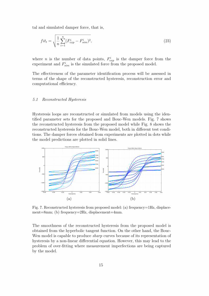
Hysteresis loops are reconstructed or simulated from models using the iden-tified parameter sets for the proposed and Bouc-Wen models. Fig. 7 showsthe reconstructed hysteresis from the proposed model while Fig. 8 shows thereconstructed hysteresis for the Bouc-Wen model, both in different test condi-tions. The damper forces obtained from experiments are plotted in dots whilethe model predictions are plotted in solid lines.
−0.06 −0.04 −0.02 0 0.02 0.04 0.06−1500
−1000
−500
0
500
1000
Velocity(m/s)
For
ce(N
)
0.00A
Freq:1.00Hz Disp:8.00mm
0.25A
0.50A
0.75A
1.00A
2.00A
(a)
−0.05 −0.04 −0.03 −0.02 −0.01 0 0.01 0.02 0.03 0.04 0.05−1500
−1000
−500
0
500
1000
Velocity(m/s)
For
ce(N
)
0.00A
Freq:2.00Hz Disp:4.00mm
0.25A
0.50A
0.75A
1.00A
2.00A
(b)
Fig. 7. Reconstructed hysteresis from proposed model: (a) frequency=1Hz, displace-ment=8mm; (b) frequency=2Hz, displacement=4mm.
The smoothness of the reconstructed hysteresis from the proposed model isobtained from the hyperbolic tangent function. On the other hand, the Bouc-Wen model is capable to produce sharp curves because of its representation ofhysteresis by a non-linear differential equation. However, this may lead to theproblem of over-fitting where measurement imperfections are being capturedby the model.
15

−0.06 −0.04 −0.02 0 0.02 0.04 0.06−1500
−1000
−500
0
500
1000
Velocity(m/s)
For
ce(N
)
0.00A
Freq:1.00Hz Disp:8.00mm
0.25A
0.50A
0.75A
1.00A
2.00A
(a)
−0.05 −0.04 −0.03 −0.02 −0.01 0 0.01 0.02 0.03 0.04 0.05−1500
−1000
−500
0
500
1000
Velocity(m/s)
For
ce(N
)
0.00A
Freq:2.00Hz Disp:4.00mm
0.25A
0.50A
0.75A
1.00A
2.00A
(b)
Fig. 8. Reconstructed hysteresis from Bouc-Wen model: (a) frequency=1Hz, dis-placement=8mm; (b) frequency=2Hz, displacement=4mm.
5.2 Identification Errors
The errors between the damper forces obtained from the experimental dataand simulated force from the models using the identified parameters are showin Fig. 9. Due to the higher degree of non-linearity in the Bouc-Wen model, alarger root-mean-square error is observed from the reconstructed or simulatedforce from the model. On the other hand, the errors found from the proposedmodel are generally less than that from the Bouc-Wen model.
0 0.2 0.4 0.6 0.8 1 1.2 1.4 1.6 1.8 20
20
40
60
80
100
120
RM
S E
rror
Current(A)
(a)
0 0.2 0.4 0.6 0.8 1 1.2 1.4 1.6 1.8 20
20
40
60
80
100
120
RM
S E
rror
Current(A)
(b)
Fig. 9. Parameter identification errors: (a) from proposed model; (b) form Bouc-Wenmodel. Legends ◦: 1Hz 4mm, ¤: 1Hz 8mm, ♦: 1Hz 12mm, >: 2Hz 4mm, ¢: 2Hz6mm and ¤: 2Hz 8mm.
5.3 Computation Efficiency
The efficiency of the identification process is affected by the complexity of themodel and the number of parameters to be identified. The proposed model
16

is simpler and the number of parameters is smaller. Hence, the identificationefficiency out-performs that from the Bouc-Wen model as show in Fig. 10(for legends, see Fig. 9). The identification of the proposed model terminatesaround 15 generations, while for the Bouc-Wen model it requires over 30 gen-erations before the same PSO algorithm terminates. Furthermore, the spreadin the number of generations before termination is smaller in the proposedmodel. This feature makes the proposed model more efficient and predictablein the paradigm of computation efficiency.
0 0.2 0.4 0.6 0.8 1 1.2 1.4 1.6 1.8 210
15
20
25
30
35
Gen
erat
ions
Current(A)
(a)
0 0.2 0.4 0.6 0.8 1 1.2 1.4 1.6 1.8 210
15
20
25
30
35
Gen
erat
ions
Current(A)
(b)
Fig. 10. Parameter identification efficiency: (a) from proposed model; (b) fromBouc-Wen model.
5.4 Generalized Parameters
The identified parameters are grouped (e.g., the viscous parameter - c) accord-ing to their experiment settings and are plotted against the supplied currentas shown in Fig. 11 (for legends, see Fig. 9). The parameter groups are thenaveraged and a polynomial is used to fit the averaged values. This results ofthis operation (shown by dotted lines in the figure) give the following set ofexpressions describing the parameters as functions of the supply current.
c = 1929i + 1232 (24)
k =−1700i + 5100 (25)
α =−244i2 + 918i + 32 (26)
β = 100 (27)
δ = 0.30i + 0.58 (28)
f0 =−18i− 257, (29)
where i is the current supplied to the MR damper.
Most of the parameters c, k, δ and f0 can be approximated using a 1st-order
17

polynomial and the relationships between the parameters and the currentbecome linear. An exception is observed from the scaling parameter α wherea 2nd-order polynomial is needed to represent the relationship to the supplycurrent. It is observed that, in particular, parameter β is approximately aconstant against the supply current values.
Consider the change of parameters with regard to the limits of allowed rangeof current supplied to the damper, i.e., from 0A to 2A. The minimum para-meter ratio is obtained from the offset f0 at 1 : 1.5 to the maximum ratio of1 : 4 obtained for the viscous damping parameter c. Furthermore, these para-meters change linearly with the supply current (approximated by a 1st-orderpolynomial). This characteristic makes the proposed model very suitable inimplementing controllers for vibration reduction in buildings.
The set of polynomial fitted parameters are used to reconstruct the hystereticresponses and compared to the experimental data shown in Fig. 12. The re-sults indicate that the matching between the reconstructed hysteresis andexperimental data is practically acceptable although the matching containssome discrepancy. It is suspected that the collected experimental data are notdepicting the physical hysteresis accurately due to measurement errors. Forexample, when the displacement is set at as small as 4mm, it becomes prac-tically difficult to precisely mount the test gears or there are dead-zone orback-slash found in the drive mechanism. Another problem may be encoun-tered is the over-fitting phenomena while the PSO algorithm is directed to fita noise corrupted or distorted hysteresis, thus giving rise to the discrepancy.
6 Conclusion
This paper has presented a new model for a magnetorheological damper torepresent the hysteretic relationship between the damping force and the ve-locity. Complexity arising from a larger number of model parameters, whenusing the Bouc-Wen model, is removed. The model parameters can be explic-itly related to the hysteretic phenomenon while still maintain physical inter-pretations for viscous damping and spring stiffness. A performance-enhancedtechnique based on particle swarm optimization is proposed for identifyingthe model parameters. A statistical hypothesis testing procedure is adoptedhere to terminate the optimization process that guaranteed the identificationquality. Experiment data from a commercial MR damper is used for modelvalidation. Results obtained by the new model have shown highly satisfac-tory coincidence with the experimental data, and also the effectiveness of theproposed identification technique.
18

0 0.2 0.4 0.6 0.8 1 1.2 1.4 1.6 1.8 20
5000
10000
150001929.4424 1231.5238
Par
am −
c
Current(A)
(a)
0 0.2 0.4 0.6 0.8 1 1.2 1.4 1.6 1.8 20
0.5
1
1.5
2
2.5x 10
4 −1663.2508 5133.0963
Par
am −
k
Current(A)
(b)
0 0.2 0.4 0.6 0.8 1 1.2 1.4 1.6 1.8 20
100
200
300
400
500
600
700
800
900
1000−244.2819 917.6953 31.86744
Par
am −
α
Current(A)
(c)
0 0.2 0.4 0.6 0.8 1 1.2 1.4 1.6 1.8 240
60
80
100
120
140
160
180
20098.666
Par
am −
β
Current(A)
(d)
0 0.2 0.4 0.6 0.8 1 1.2 1.4 1.6 1.8 20.2
0.4
0.6
0.8
1
1.2
1.4
1.60.30404 0.58375
Par
am −
δ
Current(A)
(e)
0 0.2 0.4 0.6 0.8 1 1.2 1.4 1.6 1.8 2−360
−340
−320
−300
−280
−260
−240
−220−18.21205 −265.5034
Par
am −
f 0
Current(A)
(f)
Fig. 11. Parameter identification results (−) and polynomial fitted coefficients (· · ·):(a) parameter c; (b) parameter k; (c) parameter α; (d) parameter β; (e) parameterδ and (f) parameter f0.
19

−60 −40 −20 0 20 40 60−1500
−1000
−500
0
500
1000
Velocity(mm/s)
For
ce(N
)
0.00A
Freq:1.00Hz Disp:8.00mm
0.25A
0.50A
0.75A
1.00A
2.00A
(a)
−60 −40 −20 0 20 40 60−1500
−1000
−500
0
500
1000
Velocity(mm/s)
For
ce(N
)
0.00A
Freq:2.00Hz Disp:4.00mm
0.25A
0.50A
0.75A
1.00A
2.00A
(b)
Fig. 12. Results of parameter identification: experimental data (· · ·), reconstructedhysteresis from polynomial fitted parameters (−): (a) frequency=1Hz, displace-ment=8mm; (b) frequency=2Hz, displacement=4mm.
Acknowledgement
This work is supported by Australian Research Council (ARC) DiscoveryProject Grant DP0559405, by the UTS Centre for Built Infrastructure Re-search and by the Centre of Excellence programme, funded by the ARC andthe New South Wales State Government.
References
[1] B. F. Spencer Jr. and M. K. Sain, ”Controlling buildings: a new frontier infeedback,” IEEE Control Systems Magazine, Vol. 17, No. 6, pp. 19-35, Dec.1997.
[2] T. Tse and C. C. Chang, ”Shear-mode rotary magnetorheological damper forsmall-scale structural control experiments,” J. of Structural Engineering, Vol.130, No. 6, pp. 904-911, Jun. 2004.
[3] C. W. Zhang, J. P. Ou and J. Q. Zhang, ”Parameter optimization and analysisof a vehicle suspension system controlled by magnetorheological fluid dampers,”Structural Control and Health Monitoring, (in press), 2005.
[4] G. Bossis, S. Lacis, A. Meunier and O. Volkova, ”Megnetorheological fluids,”J. of Magnetism and magnetic materials, Vol. 252, pp. 224-228, 2002.
[5] B. F. Spencer Jr., S. J. Dyke, M. K. Sian and J. D. Carlson, ”Phenomenologicalmodel for magnetorheological dampers,” J. of Engineering Mechanics, pp. 230-238, Mar. 1997.
[6] T. Butz and O. von Stryk, ”Modelling and simulation of electro- andmagnetorheological fluid dampers,” Applied Mathematics and Mechanics, Vol.82, No. 1, pp. 3-20, 2002.
20

[7] S. J. Dyke, B. F. Spencer, Jr., M. K. Sain and J. D. Carlson, ”Modeling andcontrol of magnetorheological dampers for seismis response reduction,” SmartMaterial and Strucctures, Vol. 5, pp. 565-575, 1996.
[8] S. B. Choi and S. K. Lee, ”A hysteresis model for the field-dependent dampingforce of a magnetorheological damper,” J. of Sound and Vibration, Vol. 245,No. 2, pp. 375-383, 2001.
[9] X. Q. Ma, E. R. Wang, S. Rakheja and C. Y. Su, ”Modeling hystereticcharacteristics of MR-fluid damper and model validation,” Proc. 41st IEEEConf. on Decision and Control, Las Vegas, Nevada, pp. 1675-1680, Dec. 2002.
[10] G. Jin, M. K. Sain and B. F. Spencer, Jr., ”Nonlinear blackbox modeling ofMR-dampers for civil structural control,” IEEE Trans. on Control SystemsTechnology, Vol. 13, No. 3, pp. 345-355, May 2005.
[11] K. C. Schurter and P. N. Roschke, ”Fuzzy modeling of a magnetorheologicaldamper using ANFIS,” Proc. 9th IEEE Intl. Conf. on Fuzzy Systems, SanAntonio, Texas, pp. 122-127, May 2000.
[12] D. H. Wang and W. H. Liao, ”Neural network modeling and controllers formagnetorheological fluid dampers,” Proc. 2001 IEEE Intl. Conf. on FuzzySystems, Melbourne, Australia, pp. 1323-1326, Dec. 2001.
[13] K. F. Man, K. S. Tang and S. Kwong, ”Genetic algorithms: concepts andapplications,” IEEE Trans. on Industrial Eletronics, Vol. 43, No. 5, pp. 519-534,Oct. 1996.
[14] D. E. Goldberg, ”Genetic algorithms in search, optimization and machinelearning,” Addison-Wesley, Reading, MA, 1989.
[15] M. Iwasaki, M. Miwa and N. Matsui, ”GA-based evolutionary identificationalgorithm for unknown structured mechatronic systems,” IEEE Trans. onIndustrial Electronics, Vol. 52, No. 1, pp. 300-305, Feb. 2005.
[16] G. Rudolph, ”Convergence analysis of canonical genetic algorithms,” IEEETrans. on Neural Networks, Vol. 5, No. 1, pp. 96-101, Jan. 1994.
[17] N. M. Kwok, Q. P. Ha, J. Li, B. Samali and S. M. Hong, ”Parameteridentification for a magnetorheological fluid damper: an evolutionarycomputation approach,” Proc. Sixth Intl. Conf. on Intelligent Technologies,Phuket Thailand, pp. 115-122, Dec. 2005.
[18] T. Ray and K. M. Liew, ”Society and civilization: an optimization algorithmbased on the simulation of social behavior,” IEEE Trans. on EvolutionaryComputation, Vol. 7, No. 4, pp. 386-396, Aug. 2003.
[19] M. Clerc and J. Kennedy, ”The particle swarm - explosion, stabilityand convergence in a multidimensional complex space,” IEEE Trans. onEvolutionary Computation, Vol. 6, No. 1, pp. 58-73, Feb. 2002.
[20] Z. L. Gaing, ”A particle swarm optimization approach for optimum design ofPID controller in AVR system,” IEEE Trans. on Energy Conversion, vol. 19,No. 2, pp. 384-391, Jun. 2004.
21

[21] G. Ciuprina, D. Ioan and I. Munteanu, ”Use of intelligent-particle swarmoptimization in electromagnetics,” IEEE Trans. on Magentic, Vol. 38, No. 2,pp. 1037-1040, Mar. 2002.
[22] I. C. Trelea, ”The particle swarm optimization algorithm: convergence analysisand parameter selection,” Information Processing Letters, Vol. 85, pp. 317-325,2003.
[23] L. Zipser, L. Richter and U. Lange, ”Magnetorheological fluids for actuators,”Sensors and Actuators A: Physical, Vol. 92, pp. 318-325, 2001.
[24] ”Product Bulletin and MR Damper Assembly (RD-1005-3),” LORDCorporation, www.lord.com.
22

List of Figure Captions
Fig. 1. MR damper structure.
Fig. 2. MR damper test gear.
Fig. 3. Characteristics of damper force vs. supply current: (a) non-linearity in force-displacement; (b) hysteresis in force-velocity.
Fig. 4. Hysteresis model – component-wise additive approach.
Fig. 5. Hysteresis parameters.
Fig. 6. PSO termination determined from an exponential distribution.
Fig. 7. Reconstructed hysteresis from proposed model: (a) frequency=1Hz, displacement=8mm; (b) frequency=2Hz, displacement=4mm.
Fig. 8. Reconstructed hysteresis from Bouc-Wen model: (a) frequency=1Hz, displacement=8mm; (b) frequency=2Hz, displacement=4mm.
Fig. 9. Parameter identification errors: (a) from proposed model; (b) form Bouc-Wen model.
Fig. 10. Parameter identification efficiency: (a) from proposed model; (b) from Bouc-Wen model.
Fig. 11. Parameter identification results (-) and polynomial fitted coefficients (...): (a) parameter c ; (b) parameter k ; (c) parameter α ; (d) parameter β ; (e) parameter δ ; and (f) parameter fo.
Fig. 12. Results of parameter identification: experimental data (...), reconstructed hysteresis from polynomial fitted parameters (-): (a) frequency=1Hz, displacement=8mm; (b) frequency=2Hz, displacement=4mm.
Paper SNA-D-05-00719 - Authors’ biography N.M. Kwok received the B.Sc. degree in Computer Science from the University of East Asia, Macau, the M.Phil. degree in Control Engineering from The Hong Kong Polytechnic University, Hong Kong and the PhD degree in Mobile Robotics from the University of Technology, Sydney, Australia in 1993, 1997 and 2006 respectively. He is currently a Senior Research Assistant at the University of Technology, Sydney, Australia. His research interests include evolutionary computing, robust control and mobile robotics. Q.P. Ha received the B.E. degree in Electrical Engineering from Ho Chi Minh City University of Technology, Vietnam, the Ph.D. degree in Engineering Science from Moscow Power Engineering Institute, Russia, and the Ph.D. degree in Electrical Engineering from the University of Tasmania, Australia, in 1983, 1992, and 1997, respectively. He is currently an Associate Professor at the University of Technology, Sydney, Australia. His research interests include robust control and estimation, robotics, and artificial intelligence applications. T.H. Nguyen received the B.E. degree in Electrical - Electronic Engineering from Ho Chi Minh University of Technical Education, Vietnam, the Masters degree in Telecommunication - Electronic Engineering from Ho Chi Minh City University of Technology, Vietnam, in 1995 and 2001 respectively. He is currently a Ph.D. student at the University of Technology, Sydney, Australia. J. Li received his PhD in Mechanical Engineering of University of Dublin, Ireland in 1993. He is currently a senior lecturer in Faculty of Engineering University of Technology Sydney. His research interests include structural dynamics, smart materials and smart structures and structural health monitoring and damage detections. B. Samali is the current Professor and Head of Infrastructure and the Environment disciplines at the Faculty of Engineering at the University of Technology, Sydney and has a personal chair in Structural Engineering at UTS. He is also the Director of Centre for Built Infrastructure Research at UTS. He received his Bachelor of Science in Civil Engineering with honours in 1978, Master of Science in Structural Engineering in 1980 and Doctor of Science in Structural Dynamics in 1984, all from the George Washington University in Washington DC (USA). Professor Samali has published over 250 technical papers in engineering journals and conference proceedings. His main research interests lie in the general area of structural dynamics including wind and earthquake engineering with special emphasis on structural control, dynamic measurement and analysis of buildings and bridges, and use of smart materials in engineering applications.
Related Documents