DYNAMIC POSITIONING CONFERENCE October 9-10, 2007 Design & Control Design and Commissioning of a New Thruster Assisted Mooring System (TAMS) For Global Producer III Richard I Stephens Allan Meahan Converteam, Ltd. Return to Session Directory

Welcome message from author
This document is posted to help you gain knowledge. Please leave a comment to let me know what you think about it! Share it to your friends and learn new things together.
Transcript

Return to Session Directory Doug Phillips Failure is an Option
DYNAMIC POSITIONING CONFERENCE October 9-10, 2007
Design & Control
Design and Commissioning of a New Thruster Assisted
Mooring System (TAMS) For Global Producer III
Richard I Stephens Allan Meahan
Converteam, Ltd.
Return to Session Directory

Return to Session Directory R I Stephens & A J Meahan Design and Control A New Thruster-Assisted Mooring System
DP Conference Houston October 9-10, 2007 Page 2
ABSTRACT
The paper describes the new Thruster Assisted Mooring System (TAMS) designed and installed on the Global Producer III turret-moored Floating Production Storage and Offload FPSO. The system is the first of a new generation of controllers, which include enhanced hardware, a new Human Machine Interface (HMI) and a new, robust control system specifically for moored vessels. Also included is an Advisory Prediction System (APS), based on the same hardware and HMI. The control system has been redesigned to remove the reliance on measured anchor tensions, which have proved to be notoriously unreliable, and to minimize uneconomical thruster activity. It includes new modes of operation, which reflect the desired usage and complement the mooring system, rather than fighting it. Anchor-break detection logic enables anchor breaks to be reliably identified. The APS includes the latest models of anchor catenaries and turret-moored vessel. It includes all of the required functionality for DNV classification. The experiences and results of commissioning during January and February 2007 are presented, reinforcing the success of the new systems. INTRODUCTION
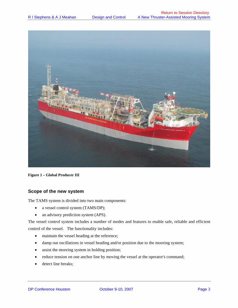
The Global Producer III (GP3) is a turret-moored Floating Production Storage and Offload (FPSO) vessel operating in the North Sea (Figure 1). She has been operating in the North Sea for a number of years in the Leadon field. As oil prices have increased, marginal fields in the North Sea have become viable prospects. In July 2006, GP3 left the Leadon field for a re-fit in Tyneside to accommodate a new topside, refurbish the azimuth thrusters and replace an ageing TAMS system. In November 2006 she began a new life on the Dumbarton field, 140 miles north east of Aberdeen. As part of her re-fit for the new field, she was equipped with an upgraded Converteam thruster-assisted mooring system (TAMS) to replace the one originally installed in 2000, releasing key spares for the vessel. With this type of vessel oil production is the key factor that dominates life onboard. The majority of crew are associated with oil production, while a small marine crew are assigned to operate the manual thrusters control system (MTC), vessel control system (VCS), power management system (PMS) and the TAMS system. Comfort of those on board is also paramount to a happy crew as this is a 24-hour operation, for example, one criticism of the old system was the level of noise from the bow thruster audible on the accommodation decks. The design of the control system needed to introduce new concepts to a) minimal intervention required from the control system – assist the mooring, b) remove the need to use tension measurements and line-outs which are notoriously unreliable and noisy and cannot be accepted within a robust system (Stephens, 2004).
Return to Session Directory R I Stephens & A J Meahan Design and Control A New Thruster-Assisted Mooring System
DP Conference Houston October 9-10, 2007 Page 3
Figure 1 – Global Producer III
Scope of the new system
The TAMS system is divided into two main components:
• a vessel control system (TAMS/DP); • an advisory prediction system (APS).
The vessel control system includes a number of modes and features to enable safe, reliable and efficient control of the vessel. The functionality includes:
• maintain the vessel heading at the reference; • damp out oscillations in vessel heading and/or position due to the mooring system; • assist the mooring system in holding position; • reduce tension on one anchor line by moving the vessel at the operator's command; • detect line breaks;

Return to Session Directory R I Stephens & A J Meahan Design and Control A New Thruster-Assisted Mooring System
DP Conference Houston October 9-10, 2007 Page 4
The main functions of the APS include:
• provide consequence analysis alarms to alert the operator of possible catastrophic failures; • provide prediction simulation of operator selected scenarios.
The vessel controller and the APS are described in the following sections.
Hardware
The upgrade of the TAMS system involved housing the new hardware in the existing consoles, minimizing the disturbance to existing plant cables. During the original installation outstations were distributed around the vessel with plant I/O connected to the closest outstation. All existing outstations would remain untouched; the new TAMS system would communicate with the outstations via the existing dual FIP network. The existing architecture associated with the TAMS and new hardware is summarized in Figure 2.
Outstation 6
Port Aft Engine Room
MTC Console
Bridge
Outstation 1
Fwd Sw’bdRoom
Outstation 2
Fwd Engine Room
Outstation 3
Stbd Aft LV Sw’bd Room
Outstation 4
Port Aft LV Sw’bd Room
Outstation 5
Stbd Aft Engine Room
Remote I/O 1
CCR
Remote I/O 2
Turret HPU Room
T1 Speed f/bT1 Speed Ref T1 Drive Status
T1 Azimuth f/bT1 Azimuth Ref T1 Azimuth Status
T5 Stbd Stern Speed f/bT5 Stbd Stern Speed Ref
T3 Port Stern Speed f/bT3 Port Stern Speed Ref
T3 Port Stern Drive Status
T5 Stbd Stern Azimuth Status
T5 Stbd Stern Azimuth f/bT5 Stbd Stern Azimuth Ref
T3 Stbd Stern Azimuth RefT3 Stbd Stern Azimuth Status
T3 Stbd Stern Azimuth f/b
T5 Stbd Stern Drive Status
DUAL FIP
DUAL Ethernet
DP/TAMS Console A
DP/TAMS Console B
Advisory/ Prediction Simulator Console
Maintenance PC
Figure 2 – architecture new and pre-upgrade
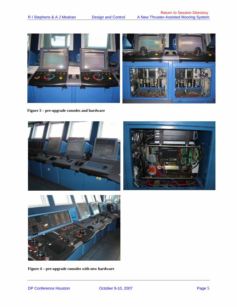
The existing consoles were stripped of the existing hardware, which now form part of the spares for the remaining automation system. The cables were carefully tagged and disconnected during the dry-docking period and reconnected when the new equipment was installed. Figure 3 and Figure 4 show the before and after stages of the upgrade.
Return to Session Directory R I Stephens & A J Meahan Design and Control A New Thruster-Assisted Mooring System
DP Conference Houston October 9-10, 2007 Page 5
Figure 3 – pre-upgrade consoles and hardware
Figure 4 – pre-upgrade consoles with new hardware

Return to Session Directory R I Stephens & A J Meahan Design and Control A New Thruster-Assisted Mooring System
DP Conference Houston October 9-10, 2007 Page 6
New user interface
The new systems also make use of an enhanced windows-based HMI. Figure 5 shows some example screenshots from the TAMS controller and APS.
Figure 5 – example screenshots from the new HMI
Vessel controller For a permanently, or semi-permanently, moored vessel like the GP3, the anchor system is the primary means of maintaining position. The forces generated by the anchor system are many times greater than those that would be possible with the thrusters supplied on the vessel. The system ‘stiffness’ of the mooring system – that is the rate of change of force with respect to position error – is far in excess of that possible with the TAMS and/or DP controller. For example, the translational stiffness of the GP3 mooring system is of the order of 200 kN/m. A normal DP system stiffness for a vessel of this type would be of the order of 20-40 kN/m.
Return to Session Directory R I Stephens & A J Meahan Design and Control A New Thruster-Assisted Mooring System
DP Conference Houston October 9-10, 2007 Page 7
Since the mooring system dominates the linear forces on the vessel, the TAMS vessel controller must be designed as a complement to the mooring. It is clear that the effect of the mooring system must be taken into account in the design and operation of the controller. A number of years ago, thruster-assisted mooring systems began to mimic the DP systems of the time and introduce Kalman filter controllers. The inherent modelling of the Kalman filter has natural advantages for the free-floating DP including improved stability margins, greater filtering of noise and wave motions and direct identification of environmental forces (Grimble et al, 1981). For a moored vessel, however, the Kalman filter required cognizance of the forces from the mooring system. Initially this was achieved by using the tension measurements from the anchors as an input to the Kalman filter model, which could then continue to predict vessel motions and identify environmental force. However, the tension measurements have proved both noisy and unreliable (Jenman, 2005).
A second generation of Kalman filter controllers now incorporates a full model of the anchor system, with catenary calculations, to enable the tension measurements to be removed from the online system. The anchor system model requires very careful design and tuning. Any changes to the operational aspects of the mooring system must be reflected in the model. While the primary aim of reducing the dependence on the tension measurements has been achieved, the added complexity of such systems threatens to undermine their robustness to equipment failure and operator error. The new TAMS controller for GP3 attempts to address this problem.
As previously stated, the TAMS controller must complement the mooring system. The mooring system can provide a very high translational stiffness, and the TAMS system can complement it by providing: a) increased damping to reduce oscillations, b) slowly varying mean thrusts to reduce loading on one or more anchor lines. As part of the design process for the new TAMS controller, an extensive simulation study was carried out to assess the benefits of various controller schemes, among them:
Kalman filter controller with tension measurements.
Kalman filter controller with integral anchor system model.
Model-less three-term (proportional-integral-derivative or PID) controller.
Some of the criteria applied were:
ability to provide damping,
ability to control the vessel’s mean position,
ease of commissioning, operation and maintenance,

Return to Session Directory R I Stephens & A J Meahan Design and Control A New Thruster-Assisted Mooring System
DP Conference Houston October 9-10, 2007 Page 8
reliance on operator and/or engineer input,
number of possible sources of failure. The results of the simulations showed that the straightforward PID controller was capable of providing the required levels of damping and position control, while scoring highest on all the other criteria. It was therefore decided to move to a PID control scheme for the new controller.
Turret-moored vessels Turret-moored vessels are a special case and require extra care when designing the controller. Figure 6 shows a scaled vessel layout for the GP3, with the turret and thruster positions marked relative to the centre-lines of the vessel. Note the position of the turret forward of the port-starboard centre-line (and also of the centre of gravity).
Figure 6 – GP3 layout
The vessel is free to rotate about the turret, although there is significant friction at the turret bearing which causes twisting of the turret and some opposing turning moment. However, the heading is largely unaffected by the mooring system, hence the control of heading requires a full three-term controller including proportional, integral and derivative terms. As noted above, the translational stiffness of the mooring system is high. All these forces act on the turret. Since the turret is located on the fore-aft centre-line, the surge axis is almost completely uncoupled from the other two axes. There is a high stiffness in surge, but the damping is low. Therefore the surge control from the TAMS controller does not require a proportional term (this is provided by the mooring), but requires integral and derivative terms for the slow mean position control and the damping. Motions in sway will induce large forces on the turret. The turret’s position forward of the centre of gravity means that the sway motions will also result in turning moments in yaw about the centre of gravity. That is, the yaw and sway axes are closely-coupled by the action of the mooring on the turret. It is necessary, therefore, to formulate the controller to take account of this interaction.
Return to Session Directory R I Stephens & A J Meahan Design and Control A New Thruster-Assisted Mooring System
DP Conference Houston October 9-10, 2007 Page 9
Since the mooring system controls the turret position, the yaw axis controller is configured to control rotation about the turret. This means that demands for turning moment from the thrusters are calculated relative to the turret, which introduces a resultant sway force at the centre of gravity. This configuration has the following advantages: The yaw axis controller is decoupled from the sway axis. The stern thrusters, with greater lever arms relative to the turret, are utilised proportionately more
than the bow thruster. The resulting system does not require direct control of the sway axis: sway damping is achieved by damping the yaw axis, and control of sway position can be achieved through a combination of surge and yaw. In order to design gains for the TAMS controller, it is necessary to estimate the stiffness of the mooring system, as seen by the vessel. The catenary modelling exercise referred to in a later section, was used to estimate the system stiffness, in order to allow controller gains to be selected beforehand which would provide adequate control with suitable stability margins. During commissioning, the system stiffness was measured directly by moving the vessel under thruster control. This measurement confirmed the initial model results.
Reducing power usage
The surge axis control includes a feature to allow the power usage of the thrusters to be minimised. The control reference (aim) position is specified along with an allowed offset. The controller is permitted to maintain the vessel the specified offset away from the aim position, if it will result in reduced thrust. That is, the controller selects the minimum thrust for any given situation in order to maintain the vessel position within the permitted region. A further economy measure is to zero the damping performance of the controllers, since the (relatively) high frequency demands for thrust changes from the damping increase full consumption significantly. They are often not required in light weather.
Control modes
The following control modes are available on the TAMS/DP system via operator interface. Anchor Monitor Monitor mode allows the operator to set up the system prior to selecting a control mode. Position alarms are active in this mode.
Return to Session Directory R I Stephens & A J Meahan Design and Control A New Thruster-Assisted Mooring System
DP Conference Houston October 9-10, 2007 Page 10
Manual Bias Manual Bias allows the operator to control the surge and yaw axes manually using the joystick and turning moment knob. Auto Heading Auto Heading allows the operator to control the surge axis manually using the joystick, with the yaw axis in automatic heading control around the turret. This aim heading is specified by the operator. Anchor Assist Anchor Assist controls the surge and yaw axis automatically. The control system uses an integral plus damping on surge and proportional, integral and damping on yaw. This aim heading can be altered by the operator. The aim turret position can also be entered by the operator, but only if the turret position is not locked to the pattern centre. The sway axis is not controlled for turret moored systems. Anchor Ecomomy Anchor Economy controls the surge and yaw axis automatically by the control system. The control system uses only integral on the surge axis and proportional plus integral on the yaw axis, with no damping. This reduces thruster activity. The heading can be altered by the operator. The position can also be entered by the operator, but only if the turret position is not locked to the pattern centre. The sway axis is not controlled for turret moored systems.
Line-break detection.
One requirement of the classification society rules for moored vessels is the provision of line-break detection (DNV, 2004). This function is required to detect, as quickly as possible, a break in one of the anchor lines and to alert the operator. A series of simulation studies was conducted to evaluate possible algorithms for this detection. The most effective detection algorithm, with the least number of false alarms, detects the presence of both of the following events:
• Step reduction of a tension measurement below a threshold. • Simultaneous motion of the vessel away from the broken line.
It must be remembered that after a line break, the tension measurement will still be significant due to the weight of the remaining cable on the fairlead. Therefore, the detection of a step change is important. If a tension sensor fails – possibly intermittently – the tension measurement may drop below this threshold, hence the second test, which monitors the velocity of the vessel and detects motion away from a possible anchor line break.

Return to Session Directory R I Stephens & A J Meahan Design and Control A New Thruster-Assisted Mooring System
DP Conference Houston October 9-10, 2007 Page 11
APS Functions
The functions of the APS include:
• consequence analysis • simulation
Catenary modeling.
Central to the APS is the ability to predict the motions of the vessel and therefore the forces acting upon it. This means that good models of the anchor lines are required. Any chain or cable which hangs under its own weight will form a catenary. The equations which govern the catenary are well-known and were first derived by Leibniz, Huygens and Bernoulli in 1691. The fundamental catenary equation is based on the hyperbolic cosine. The vertical height of the catenary curve, y, as a function of horizontal position, x, is given by:
⎟⎟⎠
⎞⎜⎜⎝
⎛=
HH Txw
Twy cosh (1)
where w is the weight per metre of the chain and TH is the horizontal component of the tension at the top (see for example Weisstein, 2007). While equation (1) appears straightforward, there are a number of complications to the simple catenary, which must be taken into account in practice:
• the tension in the cable will stretch it, giving a different final form from that of equation (1); • an anchor chain does not have two fixed end-points. Rather, the portion on the seabed lifts up as
the vessel moves away from the anchor;
• most anchor lines are made up of multiple sections of different types, with different weights and different elasticities.
The catenary equations therefore include the following information in their full form (Jenman, 2005):
• water depth • anchor co-ordinates • vessel position • line length • initial line tension • line parameters (such as weight in water, elasticity, bottom friction)
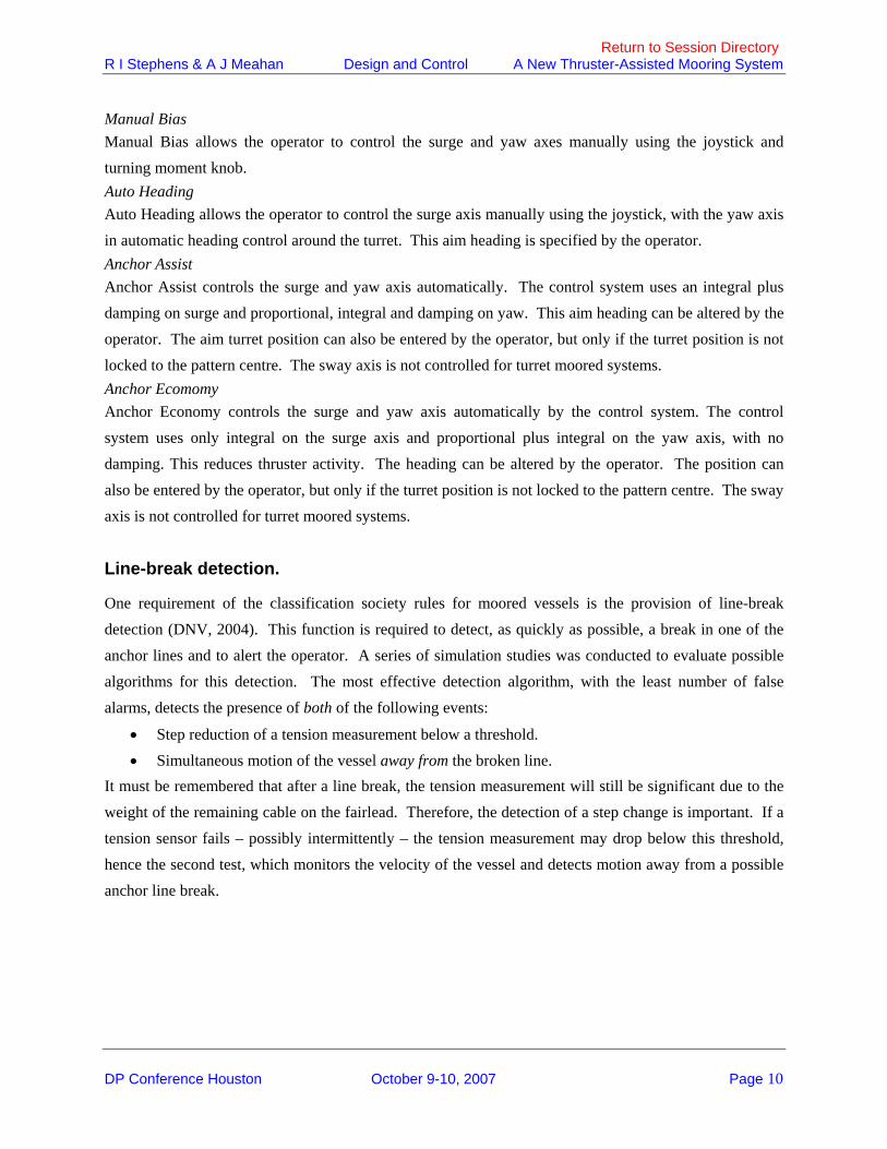
This complex behavior (mathematically speaking) is best solved by iterative means, i.e. searching for the cable touchdown point which satisfies the boundary condition of zero vertical force at the touchdown point. Figure 7 shows some example catenary curves as the vessel position (top right) moves relative to the anchor (bottom left).
Return to Session Directory R I Stephens & A J Meahan Design and Control A New Thruster-Assisted Mooring System
DP Conference Houston October 9-10, 2007 Page 12
0 200 400 600 800 1000 1200
0
100
200
Height (m)
Distance from anchor (m)
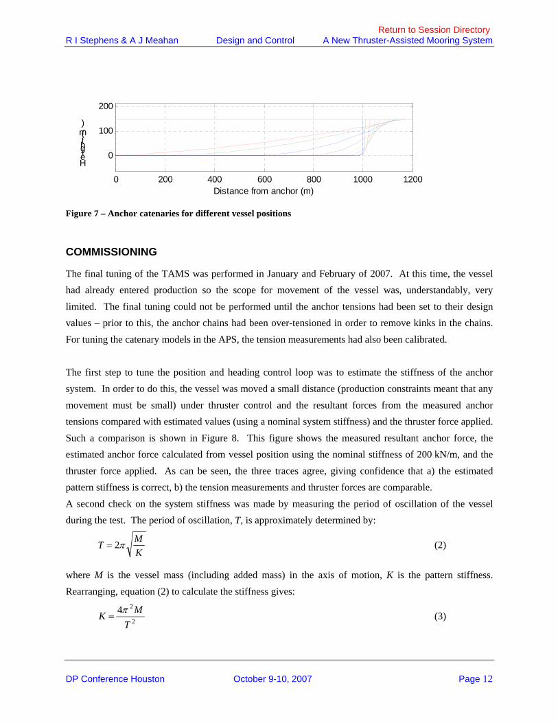
Figure 7 – Anchor catenaries for different vessel positions
COMMISSIONING
The final tuning of the TAMS was performed in January and February of 2007. At this time, the vessel had already entered production so the scope for movement of the vessel was, understandably, very limited. The final tuning could not be performed until the anchor tensions had been set to their design values – prior to this, the anchor chains had been over-tensioned in order to remove kinks in the chains. For tuning the catenary models in the APS, the tension measurements had also been calibrated. The first step to tune the position and heading control loop was to estimate the stiffness of the anchor system. In order to do this, the vessel was moved a small distance (production constraints meant that any movement must be small) under thruster control and the resultant forces from the measured anchor tensions compared with estimated values (using a nominal system stiffness) and the thruster force applied. Such a comparison is shown in Figure 8. This figure shows the measured resultant anchor force, the estimated anchor force calculated from vessel position using the nominal stiffness of 200 kN/m, and the thruster force applied. As can be seen, the three traces agree, giving confidence that a) the estimated pattern stiffness is correct, b) the tension measurements and thruster forces are comparable. A second check on the system stiffness was made by measuring the period of oscillation of the vessel during the test. The period of oscillation, T, is approximately determined by:
KMT π2= (2)
where M is the vessel mass (including added mass) in the axis of motion, K is the pattern stiffness. Rearranging, equation (2) to calculate the stiffness gives:
2
24T
MK π= (3)
Return to Session Directory R I Stephens & A J Meahan Design and Control A New Thruster-Assisted Mooring System
DP Conference Houston October 9-10, 2007 Page 13
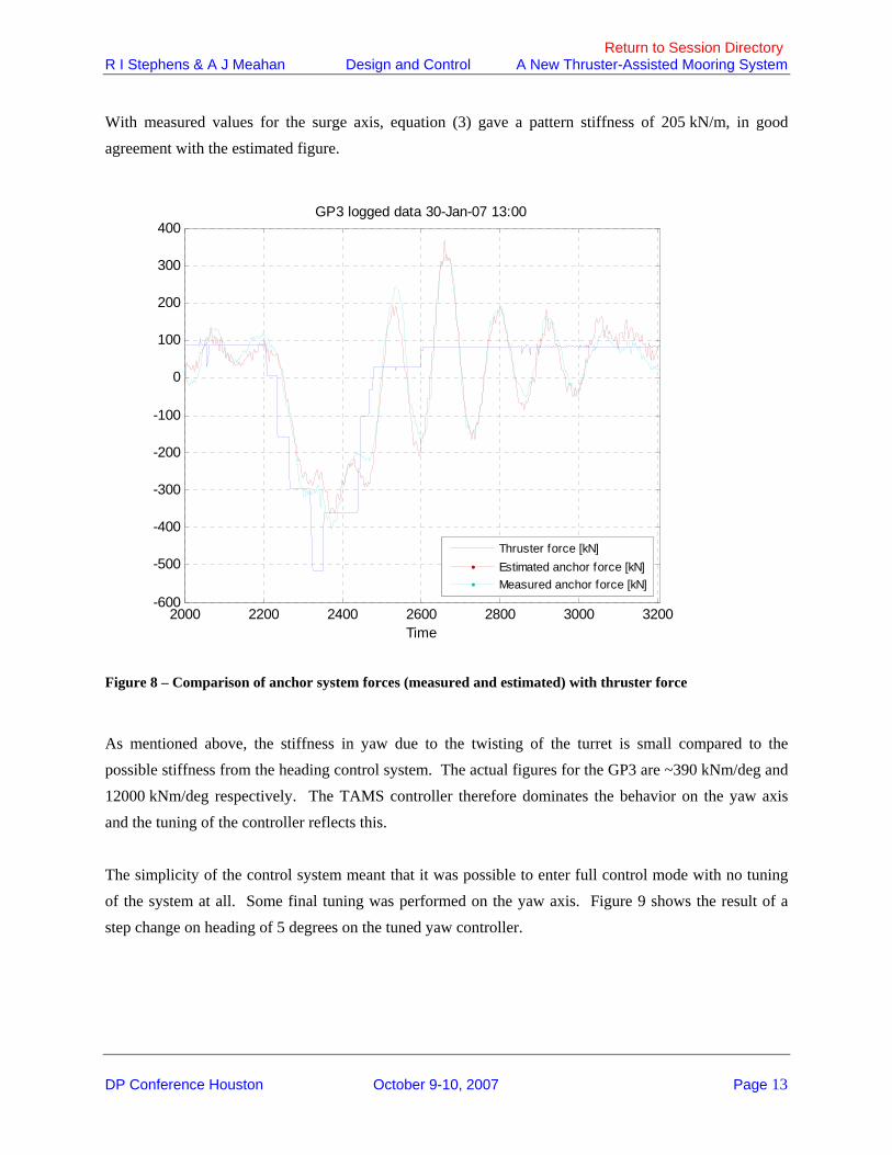
With measured values for the surge axis, equation (3) gave a pattern stiffness of 205 kN/m, in good agreement with the estimated figure.
2000 2200 2400 2600 2800 3000 3200-600
-500
-400
-300
-200
-100
0
100
200
300
400
Time
GP3 logged data 30-Jan-07 13:00
Thruster force [kN]Estimated anchor force [kN]Measured anchor force [kN]
Figure 8 – Comparison of anchor system forces (measured and estimated) with thruster force
As mentioned above, the stiffness in yaw due to the twisting of the turret is small compared to the possible stiffness from the heading control system. The actual figures for the GP3 are ~390 kNm/deg and 12000 kNm/deg respectively. The TAMS controller therefore dominates the behavior on the yaw axis and the tuning of the controller reflects this.
The simplicity of the control system meant that it was possible to enter full control mode with no tuning of the system at all. Some final tuning was performed on the yaw axis. Figure 9 shows the result of a step change on heading of 5 degrees on the tuned yaw controller.

Return to Session Directory R I Stephens & A J Meahan Design and Control A New Thruster-Assisted Mooring System
DP Conference Houston October 9-10, 2007 Page 14
23:35 23:40-5
-4
-3
-2
-1
0
1
Time
Heading error (deg)
GP3 started logging at 31-Jan-2007 23:00:01
Figure 9 – Heading step test
Tuning the APS anchor models
Once the anchor tensions had been set to their final values, and the tension measurements calibrated, it was possible to tune the anchor tension models required by the APS. First, the as-laid positions of the anchors were entered along with the measured line-out lengths of the chains. While this resulted in calculated tensions of the right order of magnitude, there is significant uncertainty over the anchor positions and line-out length, as well as possible local variations in water depth. For example, the initial tensioning of the cables could have moved the anchors slightly from their as-laid positions. It was therefore necessary to calibrate the anchor chain models by adjusting the nominal chain-out length. Figure 10 shows an example comparison of the estimated and measured tensions for one of the anchors following tuning. As can be seen, the mean tension and stiffness show good agreement.

Return to Session Directory R I Stephens & A J Meahan Design and Control A New Thruster-Assisted Mooring System
DP Conference Houston October 9-10, 2007 Page 15
The tuning was performed and checked again after a change of weather which resulted in the mean position of the vessel moving several meters from its original position. The anchor mean tensions and stiffnesses were found to be satisfactory in both cases.
18:10 18:20 18:301.05
1.1
1.15
1.2
1.25
1.3
1.35x 10⁶
Time
Tensions [N]
GP3 anchor 3 tension at 02-Feb-2007 18:00:01
MEAS_TENSION3APS_MODEL_TENSION3
Figure 10 – Comparison of measured and estimated tension for anchor 3
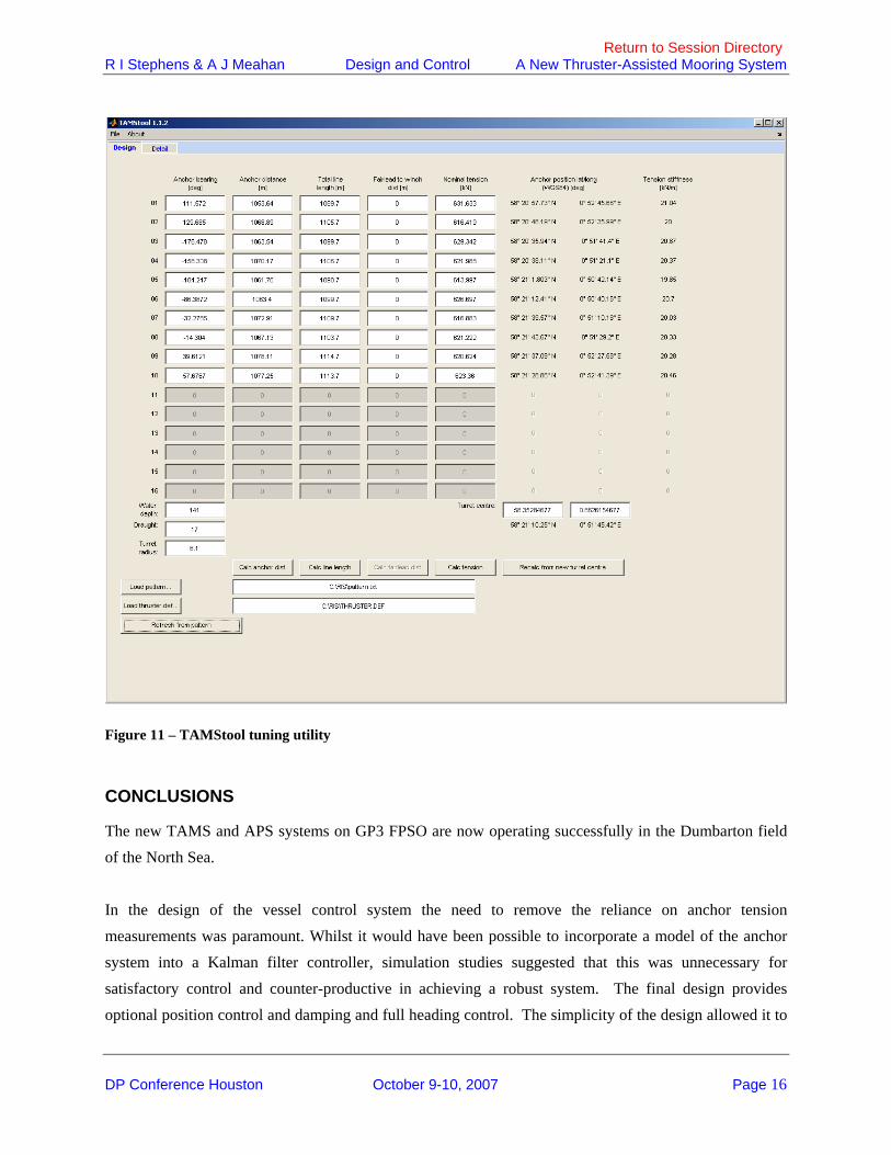
Tuning of anchor parameters was aided by the provision of an engineer's utility named "TAMStool" (Figure 11) which loads the pattern data from the configuration files and allows the tuning engineer to calculate tensions, line-out lengths and anchor positions. The utility utilizes the full catenary models and can load and re-calculate positions in lat/long. Such a tool is invaluable in assessing the impact of any changes prior to making them on the system.
Return to Session Directory R I Stephens & A J Meahan Design and Control A New Thruster-Assisted Mooring System
DP Conference Houston October 9-10, 2007 Page 16
Figure 11 – TAMStool tuning utility
CONCLUSIONS
The new TAMS and APS systems on GP3 FPSO are now operating successfully in the Dumbarton field of the North Sea. In the design of the vessel control system the need to remove the reliance on anchor tension measurements was paramount. Whilst it would have been possible to incorporate a model of the anchor system into a Kalman filter controller, simulation studies suggested that this was unnecessary for satisfactory control and counter-productive in achieving a robust system. The final design provides optional position control and damping and full heading control. The simplicity of the design allowed it to
Return to Session Directory R I Stephens & A J Meahan Design and Control A New Thruster-Assisted Mooring System
DP Conference Houston October 9-10, 2007 Page 17
enter service with no changes to the initial design gains and only straightforward final tuning once the mooring system had been finalised. Final tuning of the system was completed with no disturbance to production. The new APS system includes new catenary models for prediction of consequence analysis and predictive simulation studies by the operators. Again, tuning of the models was completed without interruption to production. The TAMStool utility has been developed to assist in the tuning of the anchor catenary models.
ACKNOWLEDGEMENTS
The authors would like to thank the owners and operators of the GP3, Maersk Oil, and especially the re-fit project team and the crew.
REFERENCES
DNV (2004). "Position Mooring", Offshore Standard DNV-OS-E301, October 2004, Det Norske Veritas, Oslo, Norway.
Grimble, M. J., Patton, R. J. and Wise, D. A. (1980). "The design of dynamic ship positioning control systems using stochastic optimal control theory", Optimal Control Applications and Methods, 1, pp. 167-202.
Jenman, C. (2005). "Mixing dynamic positioning and moorings", Dynamic Positioning Conference, Houston, 15-16 November 2005.
Stephens, R. I. (2004). “Aspects of industrial dynamic positioning: reality-tolerant control”, IFAC Conference on Control Applications in Marine Systems, CAMS 2004, 7-9 July 2004, Ancona, Italy, pp. 41-51.
Weisstein, E. W. (2007). "Catenary", from MathWorld – A Wolfram Web Resource. (http://mathworld.wolfram.com/Catenary.html)
Related Documents