A new layerwise trigonometric shear deformation theory for two-layered cross-ply beams Rameshchandra P. Shimpi *, Yuwaraj M. Ghugal Aerospace Engineering Department, Indian Institute of Technology Bombay, Powai, Mumbai, 400 076, India Abstract A new layerwise trigonometric shear deformation theory for the analysis of two-layered cross-ply laminated beams is presented. The number of primary variables in this theory is even less than that of first-order shear deformation theory, and moreover, it obviates the need for a shear correction factor. The sinusoidal function in terms of thickness coordinate is used in the displacement field to account for shear deformation. The novel feature of the theory is that the transverse shear stress can be obtained directly from the use of constitutive relationships, satisfying the shear-stress-free boundary conditions at top and bottom of the beam and satisfying continuity of shear stress at the interface. The principle of virtual work is used to obtain the governing equations and boundary conditions of the theory. The effectiveness of the theory is demonstrated by applying it to a two-layered cross-ply lami- nated beam. Keywords: Shear deformation; Laminated thick beam; Transverse shear stress; Interface shear continuity; Cross-ply beam 1. Introduction The use of fiber-reinforced composite laminates has greatly increased in weight sensitive applications such as aerospace and automotive structures because of their high specific strength and high specific stiffness. The increased use of laminated beams in various structures has stimu- lated considerable interest in their accurate analysis. On account of their low ratio of transverse shear modulus to the in-plane modulus, shear deformation effects are more pronounced in the composite beams subjected to trans- verse loads. It is well-known that the classical Euler–Bernoulli theory of beam bending, also known as elementary the- ory of bending (ETB), disregards the effects of the shear deformation. The theory is suitable for slender beams but not for thick or deep beams since it is based on the assumption that the transverse normal to the neutral axis remains so during bending and after bending, implying that the transverse shear strain is zero. Since the theory neglects the transverse shear deformation, it leads to less accurate results in the case of isotropic thick beams and more so in the case of laminated composite thick beams, where shear effects are significant. Bresse [1], Rayleigh [2], and Timoshenko [3] were the pioneer investigators who included refined effects such as the shear deformaton and rotatory inertia in the beam the- ory. Timoshenko showed that the effect of transverse shear is much greater than that of rotatory inertia on the response of transverse vibration of prismatic beams. This theory is now widely referred to as the Timoshenko beam theory in the literature. In this theory, transverse shear strain dis- tribution is assumed to be constant through the beam thickness and, thus, requires a shear correction factor to appropriately represent the strain energy of deformation. Kant and Manjunatha [4], Manjunatha and Kant [5], Maiti and Sinha [6] and Vinayak et al. [7] used the equivalent single layer, displacement based, higher-order shear deformation theories (HSDT) in the analysis of symmetric and unsymmetric laminated beams and employed the finite-element method as a solution tech- nique. These theories are the special cases of Lo et al. [8] higher-order theory. Levy [9] and Stein [10] developed refined plate the- ories expressing the displacement field in terms of trigonometric functions to represent the thickness effect and approximated the shear stress distribution through the thickness. Recently, Liu and Li [11] presented an overall com- parison of laminate theories based on displacement hypothesis emphasizing the importance of layerwise

Welcome message from author
This document is posted to help you gain knowledge. Please leave a comment to let me know what you think about it! Share it to your friends and learn new things together.
Transcript
A new layerwise trigonometric shear deformation theoryfor two-layered cross-ply beams
Rameshchandra P. Shimpi *, Yuwaraj M. GhugalAerospace Engineering Department, Indian Institute of Technology Bombay, Powai, Mumbai, 400 076, India
Abstract
A new layerwise trigonometric shear deformation theory for the analysis of two-layered cross-ply laminated beams is presented.
The number of primary variables in this theory is even less than that of first-order shear deformation theory, and moreover, itobviates the need for a shear correction factor. The sinusoidal function in terms of thickness coordinate is used in the displacementfield to account for shear deformation. The novel feature of the theory is that the transverse shear stress can be obtained directly
from the use of constitutive relationships, satisfying the shear-stress-free boundary conditions at top and bottom of the beam andsatisfying continuity of shear stress at the interface. The principle of virtual work is used to obtain the governing equations andboundary conditions of the theory. The effectiveness of the theory is demonstrated by applying it to a two-layered cross-ply lami-
nated beam.
Keywords: Shear deformation; Laminated thick beam; Transverse shear stress; Interface shear continuity; Cross-ply beam
1. Introduction
The use of fiber-reinforced composite laminates hasgreatly increased in weight sensitive applications such asaerospace and automotive structures because of their highspecific strength and high specific stiffness. The increaseduse of laminated beams in various structures has stimu-lated considerable interest in their accurate analysis. Onaccount of their low ratio of transverse shear modulus tothe in-plane modulus, shear deformation effects are morepronounced in the composite beams subjected to trans-verse loads.It is well-known that the classical Euler–Bernoulli
theory of beam bending, also known as elementary the-ory of bending (ETB), disregards the effects of the sheardeformation. The theory is suitable for slender beamsbut not for thick or deep beams since it is based on theassumption that the transverse normal to the neutral axisremains so during bending and after bending, implyingthat the transverse shear strain is zero. Since the theoryneglects the transverse shear deformation, it leads to lessaccurate results in the case of isotropic thick beams andmore so in the case of laminated composite thick beams,where shear effects are significant.
Bresse [1], Rayleigh [2], and Timoshenko [3] were thepioneer investigators who included refined effects such asthe shear deformaton and rotatory inertia in the beam the-ory. Timoshenko showed that the effect of transverse shearis much greater than that of rotatory inertia on the responseof transverse vibration of prismatic beams. This theory isnow widely referred to as the Timoshenko beam theory inthe literature. In this theory, transverse shear strain dis-tribution is assumed to be constant through the beamthickness and, thus, requires a shear correction factor toappropriately represent the strain energy of deformation.Kant and Manjunatha [4], Manjunatha and Kant [5],
Maiti and Sinha [6] and Vinayak et al. [7] used theequivalent single layer, displacement based, higher-ordershear deformation theories (HSDT) in the analysis ofsymmetric and unsymmetric laminated beams andemployed the finite-element method as a solution tech-nique. These theories are the special cases of Lo et al. [8]higher-order theory.Levy [9] and Stein [10] developed refined plate the-
ories expressing the displacement field in terms oftrigonometric functions to represent the thickness effectand approximated the shear stress distribution throughthe thickness.Recently, Liu and Li [11] presented an overall com-
parison of laminate theories based on displacementhypothesis emphasizing the importance of layerwise
theories and also presented a series of quasi-layerwisetheories.Lu and Liu [12] developed an interlaminar shear stress
continuity theory for composite laminates by using Her-mite cubic shape functions. The theory is layer dependentand the number of degrees of freedom involved is veryhigh and hence it is computationally complicated. Resultsof single-layered, two-layered and three-layered cross-ply laminates for cylindrical bending were presented.To improve the accuracy of the transverse stress pre-
diction, layerwise higher-order theories based onassumed displacements for individual layers, have beenproved to be very promising techniques in the flexuralanalysis of thick laminates. Such theories were developedand used by Lu and Liu [12], Li and Liu [13], Ambart-sumyan [14], Reddy [15] and Reddy and Robbins [16].A study of the literature indicates that, most of the
layerwise theories have been developed for symmetriccross-ply laminates subjected to cylindrical bending.Furthermore, higher order theories even with more thanthree displacement variables (e.g. there are three in thecase of FSDT) appear to be insufficient and inefficientwhen the laminated beam is unsymmetric, if the unsym-metry in the lay-up is not properly accounted for in thetheory. It is further noted that the research work dealingwith unsymmetric laminated beams using refined the-
ories is scarce. These facts have been commented uponby Vinson and Chou [17] and Icardi [18]. Thus, there isa need for a new layerwise refined shear deformationtheory with a minimum number of displacement vari-ables, for shear-deformable laminated beams.More recently, ShimpiandGhugal [19]developedasim-
ple layerwise trigonometric shear deformation theory(designatedhere asLTSDT-I) for flexural analysis of cross-ply laminated beams.However, the displacement model ofthetheorysufferedfromthedefect inthattherewasanunba-lancedsmallresultantforcealongthelengthwisedirectionofthebeam.Removing this deficiency, an improved layerwisedisplacementmodelis presented in this paper and will bereferred to as LTSDT-II.The constitutive relationships in respect of transverse
shear stress and shear strain in each layer are satisfiedand also interface shear stress continuity is satisfied inthe proposed theory. In order to verify the accuracy ofthe theory, it has been applied to two-layered cross-ply[90/0] laminated beam.
2. Theoretical formulation
The theoretical formulation of a cross-ply laminatedbeam based on certain kinematical and physical
Nomenclature
b Width of beamD Flexural rigidityD� Modified flexural rigidity coefficient
as defined in AppendixD1, D2, D3, D� 3 Constants as defined in AppendixE (1), E (2) Young’s moduli of layer 1 and layer
2, respectivelyG(1), G(2) Shear moduli of layer 1 and layer 2,
respectivelyh Depth (i.e. thickness) of beamL Span of the beamS Aspect ratio (i.e. ratio of span to
depth of beam)x, y, z Rectangular coordinates� Neutral axis coefficient as defined in
Appendixl1, l2 Coefficients as defined in Appendixu� Non-dimensional inplane displace-
mentw� Non-dimensional transverse displace-
ment��x Non-dimensional inplane stress��CRzx Non-dimensional transverse shear
stress obtained from the constitutiverelationships
��EQLzx Non-dimensional transverse shear
stress obtained from the equilibriumequations
�� z Non-dimensional transverse normalstress
SuperscriptsCR Constitutive relationshipsEQL Equilibrium equations
AcronymsESCBP Exact solution of cylindrical bending
of plateCPT Classical plate theoryETB Elementary theory of beam-bendingFSDT First-order shear deformation theoryFEM Finite element methodHSDT Higher-order shear deformation
theoryHOST Higher-order shear deformation
theoryHST Higher-order shear deformation
theoryLTSDT-I Layerwise trigonometric shear defor-
mation theory, Model ILTSDT-II Layerwise trigonometric shear defor-
mation theory, Model II
1272
assumptions is presented. The variationally correctforms of differential equations and boundary conditions,based on the assumed displacement field are obtainedusing the principle of virtual work.The beam under consideration consists of two layers:
layer 1 and layer 2.Layer 1 (90� layer) occupies the region:
04x4L; �b=24y4b=2; �h=24z40 ð1Þ
Layer 2 (0� layer) occupies the region:
04x4L; �b=24y4b=2; 04z4h=2 ð2Þ
where x, y, z are Cartesian coordinates, L is the length,b is the width and h is the total depth of beam. Thebeam is subjected to transverse load of intensity q(x) perunit length of the beam. The beam can have any mean-ingful boundary conditions.
2.1. Assumptions made in the theoretical formulation
1. The axial displacement consists of two parts:
(a) displacement which is analogous to that givenby elementary theory of bending;(b) displacement due to shear deformation, whichis assumed to be sinusoidal in nature with respectto thickness coordinate, such that maximum shearstress occurs at neutral axis as predicted by theelementary theory of bending of beam.
2. Displacement u is such that the resultant ofinplane stress, �x, acting over the cross-sectionshould result in only bending moment and shouldnot result in force in the x direction.
3. The transverse displacement is assumed to be afunction of longitudinal length coordinate of beam.
4. The displacements are small compared to beamthickness.
5. The layers are perfectly bonded to each other.6. The stacking sequence of layers is such that thereis no bending-twisting coupling.
7. The body forces are ignored in the analysis. (Thebody forces can be effectively taken into accountby adding them to the external forces.)
8. One-dimensional constitutive laws are assumed foreach layer.
9. The beam is subjected to lateral load only.
2.2. The displacement field
Based on the before mentioned assumptions, the dis-placement field of the present layerwise beam theory isgiven as below:
u 1ð Þ x; zð Þ ¼ � z� � hð Þdw
dx
þ h C1 þ C2sin�
2
z=h� �
0:5þ �
� �� �� xð Þ ð3Þ
u 2ð Þ x; zð Þ ¼ � z� � hð Þdw
dx
þ h C3 þ sin�
2
z=h� �
0:5� �
� �� �� xð Þ ð4Þ
w xð Þ ¼ w xð Þ ð5Þ
Here u(1) and u(2) are the inplane displacement com-ponents in the x direction, superscripts 1 and 2 refer tolayer 1 and layer 2, w(x) is the transverse displacementin the z direction and C1, C2, C3 and � are the constants(given in the Appendix). The function �(x) is a rotationfunction or the warping function of the cross-section ofthe beam.
2.3. Superiority of the present theory
The present theory is a displacement-based layerwisetheory, and layerwise higher-order or refined shear-deformation theories are known to be successful tech-niques for improving the accuracy of displacement andstresses [11].The kinematics of the present theory is much richer
than those of the higher order shear deformation the-ories available in the literature, because if the trigono-metric term (involving thickness coordinate z) is expandedin power series, the kinematics of higher order theories(which are usually obtained by power series in thicknesscoordinate z) are implicitly taken into account to gooddeal of extent.Also, it needs to be noted that every additional power
of thickness coordinate in the displacement field ofother higher-order theories of Lo et al. [8] type not onlyintroduces additional unknown variables in those the-ories but these variables are also difficult to interpretphysically [16]. Thus use of the sine term in the thick-ness coordinate (in the kinematics) enhances the rich-ness of the theory, and also results in the reduction ofthe number of unknown variables as compared to othertheories [5,7] without loss of physics of the problem inmodelling.The number of primary variables in this theory is even
less than that of first-order shear-deformation theory,and moreover, it obviates the need of a shear correctionfactor. Thus, the displacement field chosen is superior tothose of others.
2.3.1. StrainsNormal and transverse shear strains for layers 1
and 2
1273
1ð Þx ¼
@u 1ð Þ
@x¼ � z� � hð Þ
d2w
dx2
þ h C1 þ C2sin�
2
z=h� �
0:5þ �
� �� �d�
dx
ð6Þ
2ð Þx ¼
@u 2ð Þ
@x¼ � z� � hð Þ
d2w
dx2
þ h C3 þ sin�
2
z=h� �
0:5� �
� �� �d�
dx
ð7Þ
� 1ð Þzx ¼
@u 1ð Þ
@zþdw
dx¼
�C21þ 2�
cos�
2
z=h� �
0:5þ �
� �� ð8Þ
� 2ð Þzx ¼
@u 2ð Þ
@zþdw
dx¼
�
1� 2�cos
�
2
z=h� �
0:5� �
� �� ð9Þ
2.3.2. StressesAccording to assumption (8), one-dimensional con-
stitutive laws are used to obtain the normal bending andtransverse shear stresses for layers 1 and 2.
� 1ð Þx ¼ E 1ð Þ 1ð Þ
x ¼ E 1ð Þ
�� z� � hð Þ
d2w
dx2
þ h C1 þ C2sin�
2
z=h� �
0:5þ �
� �� �d�
dx
� ð10Þ
� 2ð Þx ¼ E 2ð Þ 2ð Þ
x ¼ E 2ð Þ
�� z� � hð Þ
d2w
dx2
þ h C3 þ sin�
2
z=h� �
0:5� �
� �� �d�
dx
� ð11Þ
� 1ð Þzx ¼ G 1ð Þ� 1ð Þ
zx ¼G 1ð Þ � C21þ 2�
cos�
2
z=h� �
0:5þ �
� �� ð12Þ
� 2ð Þzx ¼ G 2ð Þ� 2ð Þ
zx ¼G 2ð Þ �
1� 2�cos
�
2
z=h� �
0:5� �
� �� ð13Þ
2.4. Governing equations and boundary conditions
Using the expressions (6)–(13) for strains and stressesand principle of virtual work, variationally consistentdifferential equations and boundary conditions for thebeam under consideration are obtained. The principle ofvirtual work when applied to the beam leads to:
b
ðx¼L
x¼0
ðz¼0z¼�h=2
� 1ð Þx � 1ð Þ
x þ � 1ð Þzx ��
1ð Þzx
� dxdz
þ b
ðx¼L
x¼0
ðz¼þh=2
z¼0
� 2ð Þx � 2ð Þ
x þ � 2ð Þzx ��
2ð Þzx
� dx dz
�
ðx¼L
x¼0
q �w dx ¼ 0
ð14Þ
where the symbol � denotes the variational operator.Employing Green’s theorem in Eq. (14) successively
and collecting the coefficients of the primary variables
(i.e. w and �), we obtain the governing equations andthe associated boundary conditions. The governingequations are as follows:
d4w
dx4�D1
d3�
dx3�
q
D¼ 0 ð15Þ
d3w
dx3�D2
d2�
dx2þD3 � ¼ 0 ð16Þ
The associated boundary conditions obtained are ofthe following form:
d3w
dx3�D1
d2�
dx2¼ 0 or w is prescribed ð17Þ
d2w
dx2�D1
d�
dx¼ 0 or
dw
dxis prescribed ð18Þ
d2w
dx2�D2
d�
dx¼ 0 or � is prescribed ð19Þ
where D, D1, D2, D3 are the constants as defined inAppendix.Thus the variationally consistent governing differ-
ential equations and boundary conditions are obtained.The flexural behaviour of beam is given by the solutionof these equations and simultaneously satisfaction ofthe associated boundary conditions.
3. Illustrative example
A simply supported two-layered [90/0] compositebeam, wherein layers 1 and 2 occupy the regions givenby expressions (1) and (2), respectively, is considered fordetailed numerical study. The beam is subjected to sin-gle sinusoidal load q(x)=qo sin (�x=L), acting in the zdirection, where qo is magnitude of the sinusoidal load-ing at midspan. This is the same problem, which wasalso considered by Pagano [20]. The material of thebeam layers is a carbon-fibre/epoxy uni-directionalcomposite. The following has been assumed:
E 2ð Þ
E 1ð Þ¼ 25;
G 1ð Þ
E 1ð Þ¼ 0:20;
G 2ð Þ
E 2ð Þ¼ 0:02
Superscripts (1) and (2) refer to layers 1 and 2,respectively.
3.1. The solution scheme
The following is the form of the solution for w(x) and�(x) that satisfies boundary conditions perfectly:
1274
w xð Þ ¼ w1sin�x
L
� xð Þ ¼ �1cos�x
L
where w1 and �1 are constants.Using the assumed solution scheme and the governing
equations, the unknown functions w(x) and �(x) can befound. Expressions for transverse displacement w andfunction � are given as follows:
w ¼q0hS
4l1E 2ð Þb�4D�
sin�x
Lð20Þ
� ¼q0S
3l2E 2ð Þb�3D�
cos�x
Lð21Þ
where b, D� , E(2), h, S, l1 and l2 are defined in theNomenclature and/or Appendix. Substituting expres-sions for w and � given by Eqs. (20) and (21) in Eqs.(3)–(5), final expressions for in-plane displacements canbe obtained.
3.2. Expressions for inplane displacement, u
u ¼ u 1ð Þ if�h=24z40
¼ u 2ð Þ if 04z4h=2
where u(1) and u(2) are as follows:
u 1ð Þ ¼q0 h S3
E 2ð Þ b �3D�
�z
h� �
�l1 þ C1 þ C2sin
�
2
z=h� �
0:5þ �
� �� �l2
� �cos
� x
L
ð22Þ
u 2ð Þ ¼q0 h S3
E 2ð Þ b �3 D�
�z
h� �
�l1 þ C3 þ sin
�
2
z=h� �
0:5� �
� �� �l2
� �cos
� x
L
ð23ÞSubstituting expressions for w and � given by Eqs.
(20) and (21) in Eqs. (10)–(13), the final expressions forin-plane and transverse shear stresses can be obtained.
3.3. Expressions for inplane stress, sx
�x ¼ � 1ð Þx if�h=24z40
¼ � 2ð Þx if 04z4h=2
where � 1ð Þx and � 2ð Þ
x are as follows:
� 1ð Þx ¼
q0 S2
b �2 D�
E 1ð Þ
E 2ð Þ
� ��z
h� �
�l1 � l2
C1 þ C2sin�
2
z=h� �
0:5þ �
� �� ��sin
� x
L
ð24Þ
� 2ð Þx ¼
q0 S2
b �2 D�
�z
h� �
�l1 � l2
C3 þ sin�
2
z=h� �
0:5� �
� �� ��sin
� x
L
ð25Þ
3.4. Expressions for transverse shear stresses derivedfrom the constitutive relationships, tCRzx
It may be noted that it is possible to obtain transverseshear stress, �zx, by using either the constitutive rela-tionships or the equilibrium equations. Notation �CRzx
denotes �zx obtained by using constitutive relationships.
�CRzx ¼ � 1ð Þzx
� CRif�h=24z40
¼ � 2ð Þzx
� CRif 04z4h=2
where � 1ð Þzx
� CRand � 2ð Þ
zx
� CRare as follows:
� 1ð Þzx
� CR¼
q0 S3
b �3 D�
G 1ð Þ
E 2ð Þ
� �
�C2 l2 �
1þ 2�
� �cos
�
2
z=h� �
0:5þ �
� �cos
�x
Lð26Þ
� 2ð Þzx
� CR¼
q0 S3
b �3 D�
G 2ð Þ
E 2ð Þ
� �
�l2 �
1þ 2�
� �cos
�
2
z=h� �
0:5� �
� �cos
�x
Lð27Þ
3.5. Expressions for transverse shear stress, tEQLzx , and
transverse normal stress, �z, obtained from theequilibrium equations
The following equilibrium equations of two-dimen-sional elasticity, ignoring body forces, are used toobtain transverse shear and transverse normal stresses.
@�x@x
þ@�zx@z
¼ 0 ð28Þ
@�zx@x
þ@�z@z
¼ 0 ð29Þ
To obtain �zx, we integrate Eq. (28) layerwise, w.r.tthe thickness coordinate z and impose the followingboundary condition at bottom of the beam
1275
� 2ð Þzx
� z¼h=2
¼ 0 ð30Þ
and the stress-continuity condition
� 1ð Þzx
� z¼0
¼ � 2ð Þzx
� z¼0
ð31Þ
at interface to get constants of integrations and tomaintain the continuity of transverse shear stress atlayer interface.To obtain �z, we substitute the expressions obtained
for shear stresses Eq. (29) and integrate layerwise, w.r.tthe thickness coordinate z and impose the followingboundary condition at bottom of the beam
� 2ð Þzz
� z¼h=2
¼ 0 ð32Þ
and the stress-continuity condition
� 1ð Þzz
� z¼0
¼ � 2ð Þzz
� z¼0
ð33Þ
at interface to obtain constants of integrations and tomaintain the continuity of transverse normal stress atlayer interface.Using the above procedure, expressions are obtained
for transverse shear �EQLzx and transverse normal �z
stresses in their following regions of through-thicknessvariation:(Notation �EQL
zx denotes shear stress �zx as obtained byusing equilibrium equations).
�EQLzx ¼ � 1ð Þ
zx
� EQLif �h=24z40
¼ � 2ð Þzx
� EQLif 04z4h=2
�z ¼ � 1ð Þz if �h=24z40
¼ � 2ð Þz if 04z4h=2
where � 1ð Þzx
� EQL, � 2ð Þ
zx
� EQL, � 1ð Þ
z and � 2ð Þz are as follows:
� 1ð Þzx
� EQL¼
q0 S
b � D�
E 1ð Þ
E 2ð Þ
�z
h
��1
2
z
h
�2þ
E 2ð Þ
E 1ð Þ
� �1
8��
2
� �� �l1
þ C1z
h
�� C2
1þ 2�
�
� �cos
�
2
z=h� �
0:5þ �
� �� �l2
þC21þ 2�
�
� �cos
�
2
��
0:5þ �
� �l2
�E 2ð Þ
E 1ð Þ
� �C32
þ1� 2�
�
� �cos
�
2
��
0:5� �
�� �l2
8>>>>>>>>>>>><>>>>>>>>>>>>:
9>>>>>>>>>>>>=>>>>>>>>>>>>;
cos�x
L
ð34Þ
� 2ð Þzx
� EQL¼
q0 S
b � D�
�z
h
��1
2
z
h
�2þ1
8��
2
� �� �l1
þ C3z
h�1
2
� ��1� 2�
�
� �cos
�
2
z=h� �
0:5� �
� �� �l2
8>>><>>>:
9>>>=>>>;cos
�x
L
ð35Þ
� 1ð Þz ¼ �
q0
b D�
E 1ð Þ
E 2ð Þ
1
6
z
h
�3��
2
z
h
�2��
2
z
h
��1
8
z
h
�� �l1
þE 2ð Þ
E 1ð Þ
� �1
24��
8
� �l1 �
C12
z
h
�2þ
z
h
�� �l2
þC21þ 2�
�
� �2sin
�
2
z=h� �
0:5� �
� �l2
�C21þ 2�
�
� �2sin
�
2
��
0:5þ �
� �l2
�E 2ð Þ
E 1ð Þ
� �C38
þ1� 2�
�
� �21� sin
�
2
��
0:5��
�n o" #l2
8>>>>>>>>>>>>>>>>>>><>>>>>>>>>>>>>>>>>>>:
9>>>>>>>>>>>>>>>>>>>=>>>>>>>>>>>>>>>>>>>;
sin�x
L
ð36Þ
� 2ð Þz ¼ �
q0
b D�
�
1
6
z
h
�3��
2
z
h
�2�1
8
z
h
���
8þ1
24
� �l1
�C32
z
h
�2�
z
h
�þ
1
4
� �� �l2
�1� 2�
�
� �21� sin
�
2
z=h� �
0:5� �
� �� �l2
8>>>>>>><>>>>>>>:
9>>>>>>>=>>>>>>>;sin
�x
L
ð37Þ
Thus expressions for displacements and stresses havebeen obtained in their explicit forms.
4. Numerical results
The results obtained for displacements and stresses atsalient points are presented in Tables 1–6 and in Figs. 1–3 in non-dimensional parameters.
4.1. Non-dimensional displacements and stresses
The results for inplane displacement, transverse dis-placement, inplane and transverse stresses are presentedin the following non-dimensional form in this paper.
u� ¼E 1ð Þbu
qoh; w� ¼
100E 1ð Þbh3w
qoL4; ��x ¼
b�xqo
;
1276

��zx ¼b�zxqo
; �� z ¼b�zqo
The percentage difference (% Diff.) in results obtainedby models of other researchers with respect to the cor-responding results obtained by the present theory(LTSDT-II) is calculated as follows:
%Diff : ¼
value obtained by othermodel�corresponding value byLTSDT-II
value byLTSDT-II� 100
5. Discussion
For the problem under consideration, it may be notedthat the exact results are not available in the literatureto the best of the authors’ knowledge. In the absence ofexact results, researchers have compared their resultswith the exact solution for the cylindrical bending ofplate (ESCBP) obtained by Pagano [20] for compositelaminates.Kant and Manjunatha [4], Manjunatha and Kant [5],
Maiti and Sinha [6] and Vinayak et al. [7] used theequivalent single layer (ESL) theories in the analysis oflaminated beams and provided the finite element solu-tions.It is well known that the cylindrical-plate-bending
problem, though near to a beam-bending problem, is adifferent problem altogether, in which the Poisson’seffect figures. In this paper also, results obtained by Luand Liu [12] and Pagano [20] are quoted for the sake ofthe record. Also, results using elementary theory ofbeam bending are quoted.In LTSDT-II, stress/strain relationships are satisfied
in both the layers and the interface continuity fortransverse shear stress is maintained, also the closedform solution has been obtained for the problem underconsideration. Because of these reasons, it is believedthat the LTSDT-II results are superior.
5.1. In-plane displacement
The comparison of results of maximum non-dimensionalised inplane displacement and the percen-tage difference in results of other models with respect toresults of present model is shown in Table 1 for theaspect ratios 4 and 10. These displacements are calcu-lated at left end of the beam (i.e. at x=0).
(a) Results of in-plane displacement of other higher-order models and the present model are on thehigh side compared to the exact results ofcylindrical bending of plate for the aspect ratio 4as a consequence of the neglect of the Poisson’s
effect in beam theory. Results of presentLTSDT-II model and HOSTB5 beam model ofKant and Manjunath [4] are comparable within3.46%. The maximum value of this displacementusing LTSDT-II has been found to decrease by0.43% as compared to that of LTSDT-I for theaspect ratio 4.
(b) For the aspect ratio 10, the value of this dis-placement obtained by LTSDT-I is found toincrease by 0.11% when compared to LTSDT-II.The values by Lu and Liu [12] and Pagano [20]are found to decrease by 2.58% for aspect ratio10.
(c) The ETB underestimates the value by 23.28% ascompared to that of LTSDT for the aspect ratio4. For aspect ratio 10, ETB underestimates theresult by 4.66% compared to LTSDT-II. In gen-eral, ETB underpredicts the inplane displace-ments as compared to those given by higherorder models.
5.2. Transverse displacement
The variation of maximum nondimensionalisedtransverse displacement with various aspect ratios, isshown in Fig. 1. The comparison of maximum trans-verse displacements for the aspect ratios of 4 and 10 ispresented in Tables 2 and 3. It should be noted that thedeflection of cylindrical bending of a plate strip issomewhat smaller than the corresponding beam deflec-tion due to the plate action in plate strip.
(a) It is seen from the comparison that the results fortransverse displacement of present model arecomparable with the results of higher order
Fig. 1. Variation of maximum transverse deflection w� at x=0.5 L with
aspect ratio S.
1277
models of Lu and Liu [12], Vinayak et al. [7] andthe finite element solution of first order sheardeformation theory by Maiti and Sinha [6].However, higher order model of Maiti and Sinhaunderestimates the deflection by 25.49% ascompared to that given by the present model forthe aspect ratio 4 and this may be due to the lackof C1 continuity in the finite element formula-tion.
(b) For aspect ratio 10 results of LTSDT-II model,HOSTB5 model of Manjunatha and Kant [5], Luand Liu [12], model and Pagano [20] are in closeagreement with each other. No significant differ-ence is observed between the value of transversedisplacement obtained by LTSDT-II andLTSDT-I for the aspect ratio 4 and 10.
(c) The ETB underestimates the results for trans-verse displacement by 44.60% as compared toresult of LTSDT-II for the aspect ratio 4; and forthe aspect ratio 10, ETB underestimates the dis-
placement by 11.64% as compared to that of thepresent model. It is seen from the Fig. 2 that theLTSDT-II converges to the ETB results asymp-totically as the aspect ratio increases.
5.3. In-plane stress
This component of stress is directly evaluated usingthe constitutive law and strain displacement relations.The comparison of maximum nondimensionalisedinplane stresses obtained by the present theory andother refined theories is presented in the Tables 2 and 3for the aspect ratios of 4 and 10 respectively. Fig. 2shows through the thickness variation of inplane stressfor the aspect ratio 4, at midspan of beam.
(a) It can be seen that the maximum value of inplanestress obtained by LTSDT-II is comparable withthe values of Manjunatha and Kant [5], Vinayaket al. [7], Lu and Liu [12] and Pagano [20] for the
Table 1
Comparison of non-dimensional in-plane displacement (u�)
For S=4 when x=0 and z= �h=2 For S=10 when x=0 and z= �h=2
Source Model u� Percentage differencea u� Percentage differencea
Present LTSDT-II 5.0353 0.00 63.3050 0.00
Shimpi and Ghugal [19] LTSDT-I 5.0571 0.43 63.3790 0.11
Kant and Manjunatha [4] HOSTB5 4.8611 �3.46 – –
Lu and Liu [12] HSDT 4.7143 �6.37 61.6667 �2.58
Pagano [20] ESCBP 4.5000 �10.63 61.6667 �2.58
Euler–Bernoulli ETB 3.8627 �23.28 60.3540 �4.66
a Percentage difference quoted is with respect to the corresponding value obtained using LTSDT-II.
Table 2
Comparison of non-dimensional transverse displacement (w� ) and in-plane stress (��x)
For S=4
Source Model when x=0.5 L when x=0.5 L and z= �h=2 when x=0.5 L and z=h=2
w� % Diff.a ��x % Diff.a ��x % Diff.a
Present LTSDT-II 4.7437 0.00 �3.9547 0.00 30.5650 0.00
Shimpi and Ghugal [19] LTSDT-I 4.7431 �0.01 �3.9650 0.26 30.2980 �0.87
Manjunatha and Kant [5] HOSTB5 4.2828 �9.71 �3.7490 �5.20 27.0500 �11.50
FEM
Maiti and Sinha [6] HST 3.5346 �25.49 �2.3599 �40.33 25.7834 �15.64
FEM
Maiti and Sinha [6] FSDT 4.7898 0.97 �3.1514 �20.31 29.1144 �4.75
FEM
Vinayak et al. [7] HSDT 4.5619 �3.83 �4.0000 1.15 27.0000 �11.66
FEM
Lu and Liu [12] HSDT 4.7773 0.71 �3.5714 �9.69 30.0000 �1.85
Pagano [20] ESCBP 4.3276 �8.77 �3.8359 �3.00 30.0290 �1.75
Euler and Bernoulli ETB 2.6281 �44.60 �3.0386 �23.16 27.9540 �8.54
a Percentage difference quoted is with respect to the corresponding value obtained using LTSDT-II.
1278
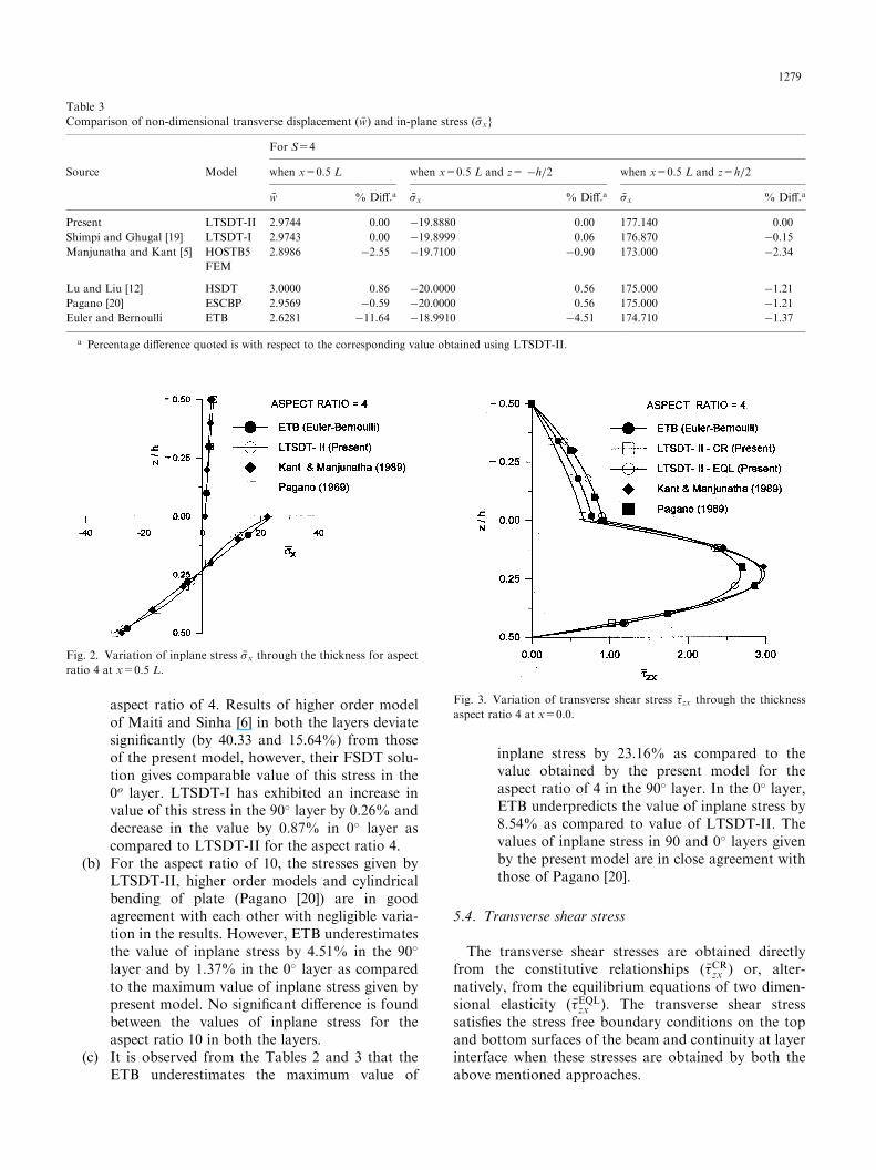
aspect ratio of 4. Results of higher order modelof Maiti and Sinha [6] in both the layers deviatesignificantly (by 40.33 and 15.64%) from thoseof the present model, however, their FSDT solu-tion gives comparable value of this stress in the0o layer. LTSDT-I has exhibited an increase invalue of this stress in the 90� layer by 0.26% anddecrease in the value by 0.87% in 0� layer ascompared to LTSDT-II for the aspect ratio 4.
(b) For the aspect ratio of 10, the stresses given byLTSDT-II, higher order models and cylindricalbending of plate (Pagano [20]) are in goodagreement with each other with negligible varia-tion in the results. However, ETB underestimatesthe value of inplane stress by 4.51% in the 90�
layer and by 1.37% in the 0� layer as comparedto the maximum value of inplane stress given bypresent model. No significant difference is foundbetween the values of inplane stress for theaspect ratio 10 in both the layers.
(c) It is observed from the Tables 2 and 3 that theETB underestimates the maximum value of
inplane stress by 23.16% as compared to thevalue obtained by the present model for theaspect ratio of 4 in the 90� layer. In the 0� layer,ETB underpredicts the value of inplane stress by8.54% as compared to value of LTSDT-II. Thevalues of inplane stress in 90 and 0� layers givenby the present model are in close agreement withthose of Pagano [20].
5.4. Transverse shear stress
The transverse shear stresses are obtained directlyfrom the constitutive relationships (��CRzx ) or, alter-natively, from the equilibrium equations of two dimen-sional elasticity (��EQL
zx ). The transverse shear stresssatisfies the stress free boundary conditions on the topand bottom surfaces of the beam and continuity at layerinterface when these stresses are obtained by both theabove mentioned approaches.
Table 3
Comparison of non-dimensional transverse displacement (w� ) and in-plane stress (��x}
For S=4
Source Model when x=0.5 L when x=0.5 L and z= �h=2 when x=0.5 L and z=h=2
w� % Diff.a ��x % Diff.a ��x % Diff.a
Present LTSDT-II 2.9744 0.00 �19.8880 0.00 177.140 0.00
Shimpi and Ghugal [19] LTSDT-I 2.9743 0.00 �19.8999 0.06 176.870 �0.15
Manjunatha and Kant [5] HOSTB5 2.8986 �2.55 �19.7100 �0.90 173.000 �2.34
FEM
Lu and Liu [12] HSDT 3.0000 0.86 �20.0000 0.56 175.000 �1.21
Pagano [20] ESCBP 2.9569 �0.59 �20.0000 0.56 175.000 �1.21
Euler and Bernoulli ETB 2.6281 �11.64 �18.9910 �4.51 174.710 �1.37
a Percentage difference quoted is with respect to the corresponding value obtained using LTSDT-II.
Fig. 2. Variation of inplane stress ��x through the thickness for aspectratio 4 at x=0.5 L.
Fig. 3. Variation of transverse shear stress ��zx through the thicknessaspect ratio 4 at x=0.0.
1279
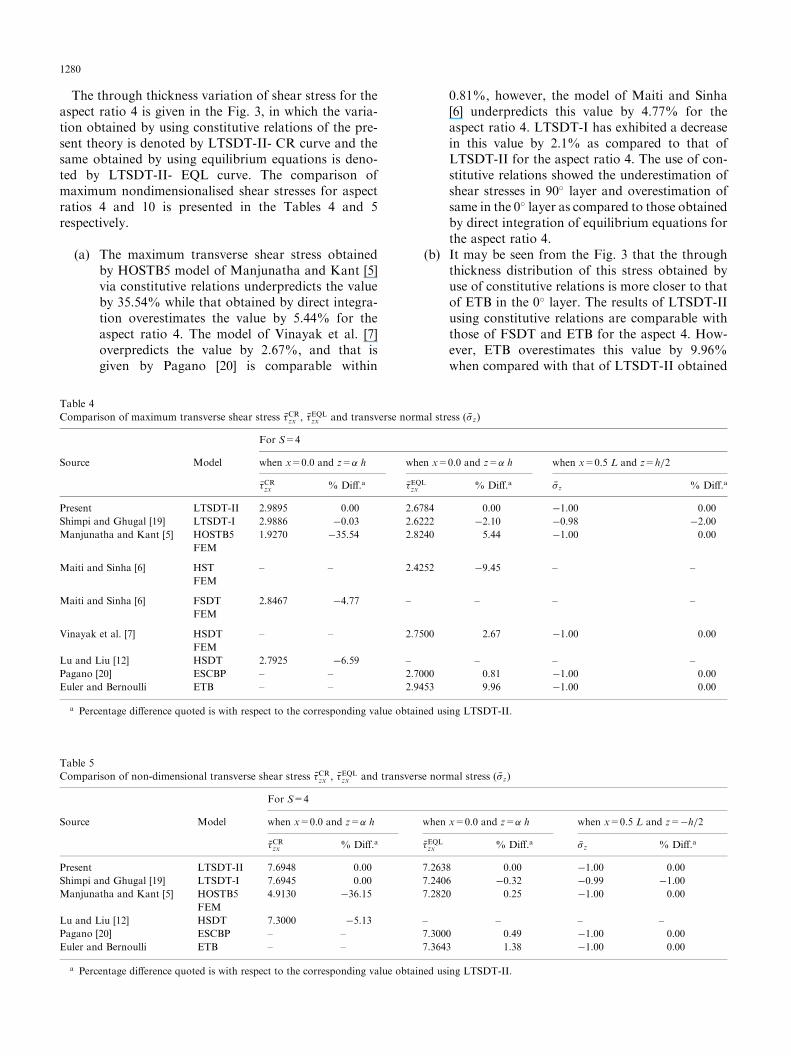
The through thickness variation of shear stress for theaspect ratio 4 is given in the Fig. 3, in which the varia-tion obtained by using constitutive relations of the pre-sent theory is denoted by LTSDT-II- CR curve and thesame obtained by using equilibrium equations is deno-ted by LTSDT-II- EQL curve. The comparison ofmaximum nondimensionalised shear stresses for aspectratios 4 and 10 is presented in the Tables 4 and 5respectively.
(a) The maximum transverse shear stress obtainedby HOSTB5 model of Manjunatha and Kant [5]via constitutive relations underpredicts the valueby 35.54% while that obtained by direct integra-tion overestimates the value by 5.44% for theaspect ratio 4. The model of Vinayak et al. [7]overpredicts the value by 2.67%, and that isgiven by Pagano [20] is comparable within
0.81%, however, the model of Maiti and Sinha[6] underpredicts this value by 4.77% for theaspect ratio 4. LTSDT-I has exhibited a decreasein this value by 2.1% as compared to that ofLTSDT-II for the aspect ratio 4. The use of con-stitutive relations showed the underestimation ofshear stresses in 90� layer and overestimation ofsame in the 0� layer as compared to those obtainedby direct integration of equilibrium equations forthe aspect ratio 4.
(b) It may be seen from the Fig. 3 that the throughthickness distribution of this stress obtained byuse of constitutive relations is more closer to thatof ETB in the 0� layer. The results of LTSDT-IIusing constitutive relations are comparable withthose of FSDT and ETB for the aspect 4. How-ever, ETB overestimates this value by 9.96%when compared with that of LTSDT-II obtained
Table 4
Comparison of maximum transverse shear stress ��CRzx , ��EQLzx and transverse normal stress (��z)
For S=4
Source Model when x=0.0 and z=� h when x=0.0 and z=� h when x=0.5 L and z=h=2
��CRzx % Diff.a ��EQLzx % Diff.a ��z % Diff.a
Present LTSDT-II 2.9895 0.00 2.6784 0.00 �1.00 0.00
Shimpi and Ghugal [19] LTSDT-I 2.9886 �0.03 2.6222 �2.10 �0.98 �2.00
Manjunatha and Kant [5] HOSTB5 1.9270 �35.54 2.8240 5.44 �1.00 0.00
FEM
Maiti and Sinha [6] HST – – 2.4252 �9.45 – –
FEM
Maiti and Sinha [6] FSDT 2.8467 �4.77 – – – –
FEM
Vinayak et al. [7] HSDT – – 2.7500 2.67 �1.00 0.00
FEM
Lu and Liu [12] HSDT 2.7925 �6.59 – – – –
Pagano [20] ESCBP – – 2.7000 0.81 �1.00 0.00
Euler and Bernoulli ETB – – 2.9453 9.96 �1.00 0.00
a Percentage difference quoted is with respect to the corresponding value obtained using LTSDT-II.
Table 5
Comparison of non-dimensional transverse shear stress ��CRzx , ��EQLzx and transverse normal stress (��z)
For S=4
Source Model when x=0.0 and z=� h when x=0.0 and z=� h when x=0.5 L and z=�h=2
��CRzx % Diff.a ��EQLzx % Diff.a ��z % Diff.a
Present LTSDT-II 7.6948 0.00 7.2638 0.00 �1.00 0.00
Shimpi and Ghugal [19] LTSDT-I 7.6945 0.00 7.2406 �0.32 �0.99 �1.00
Manjunatha and Kant [5] HOSTB5 4.9130 �36.15 7.2820 0.25 �1.00 0.00
FEM
Lu and Liu [12] HSDT 7.3000 �5.13 – – – –
Pagano [20] ESCBP – – 7.3000 0.49 �1.00 0.00
Euler and Bernoulli ETB – – 7.3643 1.38 �1.00 0.00
a Percentage difference quoted is with respect to the corresponding value obtained using LTSDT-II.
1280
by equilibrium equations, for the aspect ratio 4.(c) For aspect ratio 10, the model of Manjunatha
and Kant [5], using constitutive relations, under-estimates the maximum value of this stress by36.15% and that of Lu and Liu [12] under-predicts it by 5.13% as compared to thatobtained by LTSDT-II. The value of this stressin LTSDT-II, obtained by equilibrium equa-tions, is in excellent agreement with other solu-tions as can be seen from Table 5 for aspect ratio10.
This difference in transverse shear stresses obtainedby use of constitutive relations (CR) and equilibriumequations (EQL) is well known in the bending analysisof laminated beams/plates [5,21]. Since the displacementsolution can not give these stresses accurately whenconstitutive relations are used, many authors [22] sug-gested use of stress equilibrium equations of elasticity toobtain the transverse shear and transverse normalstresses through the thickness of the laminated beamsmore accurately, but their approach has been adverselycommented upon by Liu and Li [11], Bisegna and Sacco[23]. Furthermore, this approach is more tedious com-pared to the approach using constitutive relations.The discrepancy in the shear stresses obtained by
constitutive relations and by integration of equilibriumequations is much less in the present case as comparedto other attempts [5]. Furthermore, overall distributionof the shear stress obtained via constitutive relations isreasonably accurate.The difference between results is due to the two dif-
ferent approaches used to evaluate the stresses.
5.5. Transverse normal stress
The transverse normal stress is obtained by directintegration of equilibrium equations of two dimensionalelasticity. The comparison of through thickness varia-tion of this stress component is presented in the Table 6
for the aspect ratio of 4. An improved through thethickness variation of this stress is obtained by the pre-sent model as compared to that given by the LTSDT-Imodel. The results for this stress component obtainedby the present model LTSDT-II are in good comparisonwith those of HOSTB5 model of Manjunatha and Kant[5], ETB, and exact solution of cylindrical bending ofplate obtained by Pagano [20].The above discussion in respect of the numerical
example, validates the efficacy of the LTSDT-II model.
6. Conclusions
In this paper a new model has been presented forcross-ply [90/0] laminated composite beam. This modelis an improvement over the earlier model developed bythe authors. The earlier model suffered from the defectin that there was an unbalanced small resultant forcealong the lengthwise direction of the beam. This defi-ciency has been removed in the present model. The dis-placement based model LTSDT-II presented in thispaper has following advantages:
1. It is a displacement based layerwise model.2. The number of displacement variables is less thanthat in first order shear deformation theory. Itcontains only two variables.
3. Transverse shear stress satisfies continuity condi-tions at layer interface and zero shear stress con-ditions at top and bottom surfaces of the beam.
4. The model does not require the use of shear cor-rection factor.
5. Constitutive relations are satisfied in both the lay-ers in respect of inplane stress and transverse shearstress.
6. It is possible to get reasonable accuracy of trans-verse shear stress even when the shear stress isobtained by the use of constitutive relations.
Table 6
Comparison of variation of non-dimensional transverse normal stress (��z) through the thickness of beam (��z at x=0.5 L and S=4)
LTSDT-II LTSDT-I HOSTB5 ETB ESCBP
z/h Present Shimpi and Ghugal [19] Manjunatha and Kant [5] Pagano [20]
�0.5 �1.0000 �0.9803 �1.0000 �1.0000 �1.0000
�0.4 �0.9886 �0.9688 �0.9869 �0.9911 �0.9737
�0.3 �0.9571 �0.9373 �0.9552 �0.9660 �0.9605
�0.2 �0.9097 �0.8897 �0.9087 �0.9274 �0.9211
�0.1 �0.8500 �0.8298 �0.8508 �0.8777 �0.8684
0.0 �0.7815 �0.7609 �0.7848 �0.8197 �0.7894
0.1 �0.6525 �0.6393 �0.6581 �0.6951 �0.6711
0.2 �0.4574 �0.4500 �0.4578 �0.4869 �0.4605
0.3 �0.2499 �0.2467 �0.2432 �0.2590 �0.2500
0.4 �0.0768 �0.0759 �0.0716 �0.0754 �0.0789
0.5 0.0000 0.0000 0.0000 0.0000 0.0000
1281
7. The governing differential equations and theboundary conditions are variationally consistent.
8. The use of the present model gives accurate results,as has been seen from the numerical example stu-died.
Appendix
(a) Layer 1 integration constants A1, A2, A3, A4 are asfollows:
A1 ¼ b h3 E 1ð Þ 1
24þ�
4þ�2
2
� �
A2 ¼ b h3 E 1ð Þ
C11
8þ�
2
� �
þC21þ 2�
�
� �21þ sin
���
1þ 2�
� �� �
þ� C21þ 2�
�
� �cos
���
1þ 2�
� �
8>>>>>>><>>>>>>>:
9>>>>>>>=>>>>>>>;
A3 ¼ b h3 E 1ð Þ
C212
� 2C1 C21þ 2�
�
� �cos
�� �
1þ 2�
� �
þC2
41þ
1þ 2�
�
� �sin
� �
0:5þ �
� �� �8>><>>:
9>>=>>;
A4 ¼b h G 1ð Þ
4
C2 �
1þ 2�
� �21þ
1þ 2�
�
� �sin
���
0:5þ �
� �� �
(b) Layer 2 integration constants B1, B2, B3, B4 are asfollows:
B1 ¼ b h3 E 2ð Þ 1
24��
4þ�2
2
� �
B2 ¼ b h3 E 2ð Þ
C31
8��12
� �
þ1� 2�
�
� �21þ sin
��
1� 2�
�h i��
1� 2�
�
� �cos
���
1� 2�
�
8>>>>>>><>>>>>>>:
9>>>>>>>=>>>>>>>;
B3 ¼ b h3 E 2ð Þ
C232
þ 2 C31� 2�
�
� �cos
�� �
1� 2 �
�þ1
41�
1� 2�
�
� �sin
� �
0:5� �
�� �8>><>>:
9>>=>>;
B4 ¼b h G 2ð Þ
4
�
1� 2�
�21�
1� 2�
�
� �sin
���
0:5� �
�� �
(c) Constants C1, C2, C3 are as follows:
C1 ¼E 2ð Þ
E 1ð Þ þ E 2ð Þ
� �
�
sin�� �
1� 2�
�� C2sin
�� �
1þ 2�
� �
þ2 C2E 1ð Þ
E 2ð Þ
� �1þ 2�
�
� �cos
� �
1þ 2�
� �
�21� 2�
�
� �cos
� �
1� 2�
�
8>>>>>><>>>>>>:
9>>>>>>=>>>>>>;
C2 ¼G 2ð Þ
G 1ð Þ
0:5þ �
0:5� �
cos�� �
1� 2 �
�cos
�� �
1þ 2 �
� �
C3 ¼E 1ð Þ
E 1ð Þ þ E 2ð Þ
� � �sin�� �
1� 2�
�� C2sin
�� �
1þ 2�
� �
þ2 C21þ 2�
�
� �cos
� �
1þ 2�
� �
�2E 2ð Þ
E 1ð Þ
� �1� 2�
�
� �cos
� �
1� 2�
�
8>>>>>><>>>>>>:
9>>>>>>=>>>>>>;
(d) Constants D, D� , D1, D2, D3, D� 3 are as follows:
D ¼ A1 þ A2ð Þ ¼ D� E 2ð Þ b h3
D� ¼E 1ð Þ
E 2ð Þ
� �1
24þ�
4þ�2
2
� �þ
1
24��
4þ�2
2
� �
D1 ¼A2 þ B2A1 þ B1
� �; D2 ¼
A3 þ B3A2 þ B2
� �;
D3 ¼A4 þ B4A2 þ B2
� �
D� 3 ¼ D3 h2
(e) Constants S, �, l1, l2, are as follows:
S ¼ L=h
� ¼1
4
E 2ð Þ � E 1ð Þ
E 2ð Þ þ E 1ð Þ
� �
l1 ¼ 1þD1= D2 �D1 þD� 3 2h i
l2 ¼ 1= D2 �D1 þD� 3 2h i
¼ S=�
1282
References
[1] Bresse JAC. Cours de mecanique applique. Paris: Mallet-Bache-
lier, 1859.
[2] Rayleigh JWSLord. The theory of sound. London: Macmillan
Publishers, 1877.
[3] Timoshenko SP. On the correction for shear of the differential
equation for transverse vibrations of prismatic bars. Philosophi-
cal Magazine, Series 6 1921;41:742–6.
[4] Kant T, Manjunatha BS. Refined theories for composite and
sandwich beams with C0 finite elements. Computers and Struc-
tures 1989;33:755–64.
[5] Manjunatha BS, Kant T. Different numerical techniques for the
estimation of multiaxial stresses in symmetric / unsymmetric
composite and sandwich beams with refined theories. Journal of
Reinforced Plastics and Composites 1993;12:2–37.
[6] Maiti DK, Sinha PK. Bending and free vibration analysis of
shear deformable laminated composite beams by finite element
method. Composite Structures 1994;29:421–31.
[7] Vinayak RU, Prathap G, Naganarayana BP. Beam elements
based on a higher order theory — I: formulation and analysis of
performance. Computers and Structures 1996;58:775–89.
[8] Lo KH, Christensen RM, Wu EM. A higher order theory for
plate deformations, Part 2: laminated plates. ASME Trans Jour-
nal of Applied Mechanics 1977;44:669–76.
[9] Levy M. Memoire sur la theorie des plaques elastiques planes.
Journal des Mathematiques Pures et Appliquees 1877;30:219–
306.
[10] Stein M. Nonlinear theory for plates and shells including the
effects of transverse shearing. AIAA Journal 1986;24:1537–44.
[11] Liu D, Li X. An overall view of laminate theories based on dis-
placement hypothesis. Journal of Composite Materials 1996;
30:1539–61.
[12] Lu X, Liu D. An interlaminar shear stress continuity theory for
both thin and thick composite laminates. ASME Trans Journal
of Applied Mechanics 1992;59:502–9.
[13] Li X, Liu D. Zig-zag theory for composite laminates. AIAA
Journal 1994;33:1163–5.
[14] Ambartsumyan SA. Theory of anisotropic plates., Technomic
Publication, Stamford, CT, 1969 (Translated from Russian edi-
tion by T. Cheron and edited by J. E. Ashton).
[15] Reddy JN. A generalisation of two-dimensional theories of lami-
nated composite plates. Communications in Applied Numerical
Methods 1987;3:173–80.
[16] Reddy JN, Robbins DH Jr. Theories and computational models
for composite laminates. Applied Mechanics Reviews 1994;
47:147–69.
[17] Vinson JR, Chou TW. Composite materials and their use in
structures. London: Applied Science, 1975 (Chapter 6, pp. 234–
235).
[18] Icardi U. Eight-noded zig-zag element for deflection and stress
analysis of plates with general lay-up. Composites Part B
1998;29B:411–25.
[19] Shimpi RP, Ghugal YM. A layerwise trigonometric shear defor-
mation theory for two layered cross-ply laminated beams. Jour-
nal of Reinforced Plastics and Composites 1999;18:1516–42.
[20] Pagano NJ. Exact solution for composite laminates in cylindrical
bending. Journal of Composite Materials 1969;3:398–411.
[21] Cho M, Parmerter RR. Efficient higher order composite plate
theory for general lamination configurations. AIAA Journal
1993;31:1299–306.
[22] Lo KH, Christensen RM, Wu EM. Stress solution determination
for high order plate theory. International Journal of Solids and
Structures 1978;14:655–62.
[23] Bisegna P, Sacco E. A layerwise laminate theory rationally
deduced from the three-dimensional elasticity. Trans ASME,
Journal of Applied Mechanics 1997;64:538–45.
1283
Related Documents