A new computational algorithm for contact friction modeling of large plastic deformation in powder compaction processes A.R. Khoei * , S.O.R. Biabanaki, A.R. Vafa, I. Yadegaran, Sh. Keshavarz Center of Excellence in Structural and Earthquake Engineering, Department of Civil Engineering, Sharif University of Technology, P.O. Box. 11365-9313, Tehran, Iran article info Article history: Received 12 October 2007 Received in revised form 10 August 2008 Available online 6 September 2008 Keywords: Powder compaction Contact friction Node-to-surface algorithm Cap plasticity Large deformation abstract In this paper, the large deformation frictional contact of powder forming process is mod- eled based on a new computational algorithm by imposing the contact constraints and modifying the contact properties of frictional slip. A simple and efficient numerical algo- rithm is presented for imposing the contact constraints and frictional contact properties based on the node-to-surface contact technique to simulate the large deformation contact problem in the compaction process of powder. The Coulomb friction law is used to simu- late the friction between the rigid punch and the workpiece by the use of penalty approach. A double-surface cap plasticity model is employed together with the nonlinear contact friction algorithm within the framework of large FE deformation in order to predict the non-uniform relative density distribution during large deformation of powder die-pressing. Finally, the numerical schemes are examined for accuracy and efficiency in modeling of a set of powder components. Ó 2008 Elsevier Ltd. All rights reserved. 1. Introduction Contact friction is among the most difficult nonlinear problem since the response in contact interface is not smooth. In powder compaction process, the friction between the powder and tools limits the performances of the process and the mechanical characteristics of the parts. Friction can result in poor density distributions, which leads to differential retreat during compaction and sintering of the final properties of the component. Many aspects of the process are affected by friction, including: the density distribution, pressing forces, final shape, tool wear, residual stresses and cracks. In contact friction modeling, the tangential velocities along the interface are discontinues due to the stick-slip behavior between the powder and punches. These characteristics of contact introduce significant difficulties in the time integration of the discrete equations. Up to date, the most computational aspects of powder forming processes have been presented in large elasto- plasticity deformations (Khoei, 2005). However, to the knowledge of authors less numerical modeling has been reported in the description of complex phenomena along the contact surface between the powder and tools. A number of experimental and numerical investigations into frictional effects and its impact on the compaction process of powder have been reported in the literature. Tabata et al. (1980) determined the coefficients of friction between the powder and die wall in compaction of iron powder. Ernst et al. (1991) measured the friction coefficients with the impact of lubricants on the compaction and ejection force balance. The effects of friction between the powder and the mandrel were investigated by Kim and Lee (1998) under cold isostatic pressing. They determined the friction coefficients between the powder and man- drel with different surface roughness from the relationship between the compaction pressure and the ejection pressure of the mandrel from powder compacts. Cameron and Gethin (2001) proposed a micromechanical discrete-element modeling 0020-7683/$ - see front matter Ó 2008 Elsevier Ltd. All rights reserved. doi:10.1016/j.ijsolstr.2008.08.034 * Corresponding author. Tel.: +98 21 6600 5818; fax: +98 21 6601 4828. E-mail address: [email protected] (A.R. Khoei). International Journal of Solids and Structures 46 (2009) 287–310 Contents lists available at ScienceDirect International Journal of Solids and Structures journal homepage: www.elsevier.com/locate/ijsolstr

Welcome message from author
This document is posted to help you gain knowledge. Please leave a comment to let me know what you think about it! Share it to your friends and learn new things together.
Transcript

International Journal of Solids and Structures 46 (2009) 287–310
Contents lists available at ScienceDirect
International Journal of Solids and Structures
journal homepage: www.elsevier .com/locate / i jsols t r
A new computational algorithm for contact friction modeling of largeplastic deformation in powder compaction processes
A.R. Khoei *, S.O.R. Biabanaki, A.R. Vafa, I. Yadegaran, Sh. KeshavarzCenter of Excellence in Structural and Earthquake Engineering, Department of Civil Engineering, Sharif University of Technology, P.O. Box. 11365-9313, Tehran, Iran
a r t i c l e i n f o
Article history:Received 12 October 2007Received in revised form 10 August 2008Available online 6 September 2008
Keywords:Powder compactionContact frictionNode-to-surface algorithmCap plasticityLarge deformation
0020-7683/$ - see front matter � 2008 Elsevier Ltddoi:10.1016/j.ijsolstr.2008.08.034
* Corresponding author. Tel.: +98 21 6600 5818;E-mail address: [email protected] (A.R. Khoei).
a b s t r a c t
In this paper, the large deformation frictional contact of powder forming process is mod-eled based on a new computational algorithm by imposing the contact constraints andmodifying the contact properties of frictional slip. A simple and efficient numerical algo-rithm is presented for imposing the contact constraints and frictional contact propertiesbased on the node-to-surface contact technique to simulate the large deformation contactproblem in the compaction process of powder. The Coulomb friction law is used to simu-late the friction between the rigid punch and the workpiece by the use of penalty approach.A double-surface cap plasticity model is employed together with the nonlinear contactfriction algorithm within the framework of large FE deformation in order to predict thenon-uniform relative density distribution during large deformation of powder die-pressing.Finally, the numerical schemes are examined for accuracy and efficiency in modeling ofa set of powder components.
� 2008 Elsevier Ltd. All rights reserved.
1. Introduction
Contact friction is among the most difficult nonlinear problem since the response in contact interface is not smooth. Inpowder compaction process, the friction between the powder and tools limits the performances of the process and themechanical characteristics of the parts. Friction can result in poor density distributions, which leads to differential retreatduring compaction and sintering of the final properties of the component. Many aspects of the process are affected byfriction, including: the density distribution, pressing forces, final shape, tool wear, residual stresses and cracks. In contactfriction modeling, the tangential velocities along the interface are discontinues due to the stick-slip behavior between thepowder and punches. These characteristics of contact introduce significant difficulties in the time integration of the discreteequations. Up to date, the most computational aspects of powder forming processes have been presented in large elasto-plasticity deformations (Khoei, 2005). However, to the knowledge of authors less numerical modeling has been reportedin the description of complex phenomena along the contact surface between the powder and tools.
A number of experimental and numerical investigations into frictional effects and its impact on the compaction process ofpowder have been reported in the literature. Tabata et al. (1980) determined the coefficients of friction between the powderand die wall in compaction of iron powder. Ernst et al. (1991) measured the friction coefficients with the impact of lubricantson the compaction and ejection force balance. The effects of friction between the powder and the mandrel were investigatedby Kim and Lee (1998) under cold isostatic pressing. They determined the friction coefficients between the powder and man-drel with different surface roughness from the relationship between the compaction pressure and the ejection pressure ofthe mandrel from powder compacts. Cameron and Gethin (2001) proposed a micromechanical discrete-element modeling
. All rights reserved.
fax: +98 21 6601 4828.

288 A.R. Khoei et al. / International Journal of Solids and Structures 46 (2009) 287–310
to investigate the friction mechanisms between the powder and tool set surfaces in die compaction. The effect of wall frictionbetween powder-die and powder-punches was investigated by Sinka et al. (2003) in the compaction of pharmaceutical tab-lets, where the die and punches were lubricated and unlubricated.
The treatment of contact problem with finite element method dates back to 1970s. The early attempts were mainly to-wards the solution of small deformation frictionless problems (Beer, 1985). The large deformation/large sliding modelingwas then performed based on the node-to-segment algorithm using the bilinear discretization of contacting bodies(Wriggers et al., 1985, 1990). The penalty and Lagrange multiplier methods were applied to enforce contact constraints(Chaudaray and Bathe, 1986; Peric and Owen, 1992). The domination of these approaches was due to their successful appli-cations in other types of mechanics problems and their well-understood mathematical structure. Some other techniques,such as the perturbed Lagrange multiplier method and augmented Lagrange multiplier method were proposed and appliedwithin finite element algorithms (Simo et al., 1985; Pietrzak and Curnier, 1999). In the concept of large deformation/largesliding contact problems, fundamental works were appeared by Laursen and Simo (1993,). In relation with large scale com-putations, the significance of contact detection algorithms was realized long ago as far as the computational time and effortis concerned (Benson and Hallquist, 1990; Belyschko and Neal, 1991). The computational algorithms have been mainlytowards the contact formulation with structural elements and contact smoothing techniques in which the faceted geometryof finite element discretization is replaced by a smooth geometric approximation. Such a smooth description leads to con-tinuous contact force distributions which would have some sharp changes with conventional finite element discretizationunless a very fine mesh is used.
The contact friction is generally simulated in accordance with the Coulomb friction law, which takes into account thedependence of friction forces on contact pressure, displacement jump and material properties of contact surface (Wriggerset al., 1990). From the numerical point of view, the most important work related with the Coulomb friction law was pre-sented by Curnier and Alart (1988), where the analogy between plasticity and frictional constitutive laws was recognized.Within the numerical context, the efforts of Giannakopoulos (1989) indicated the applicability of integration schemes usedin plasticity theory to the laws describing friction phenomena.
The objective of present study is focused on a computational algorithm for simulation of large deformation contact prob-lem based on the node-to-surface contact algorithm in the compaction process of powder. The plan of the paper is as follows;in Section 2, a general formulation of continuum model is presented for large FE deformation based on the Lagrangiandescription. Section 3 is devoted to the frictional contact formulation and its computational algorithm for analyzing the phe-nomena. The implementation of penalty approach into the node-to-surface contact modeling together with the plasticitytheory of friction are demonstrated in this section. In Section 4, the double-surface cap plasticity is presented for descriptionof powder behavior. In Section 5, numerical simulation of several complicated die geometries are presented. Finally, someconcluding remarks are given in Section 6.
2. Large deformation finite element
In nonlinear elasto-plastic analyses, whether the displacements, or strains, are large or small it is imperative that theequilibrium conditions between the internal and external forces are satisfied. The equilibrium equation of a body can betherefore written in a standard form as
oPji
oXjþ bi ¼ 0; ð1Þ
where Xj is the Lagrangian coordinate, bi is the body force and Pji is the nominal stress. The above differential equation iswritten in the reference configuration, which is the initial configuration for the Lagrangian description. A generaldescription of strains was introduced by Green and St. Venant, in which the non-linear strain displacement relationshipcan be defined in terms of the infinitesimal and large displacement components, i.e. E = EL + ENL, with EL and ENL denot-ing the linear and nonlinear strains. In small displacement theory, the general first-order linear strain approximation isobtained by neglecting the quadratic terms. In this relation, the nonlinear terms of strain ENL can be defined byENL ¼ ð1=2ÞAhh, with h denoting the displacement gradient and Ah a suitably defined matrix operator which contains dis-placement derivatives.
In order to develop a finite element formulation, we need to solve Eq. (1) numerically for spatial discretization. Followingthe standard procedure of the finite element method, the initial domain X is divided into elements. If the displacementswithin an element are prescribed in the usual manner by a finite number of nodal values, we can obtain the equilibriumequations using the virtual work principle. Thus, Eq. (1) can be written in the weak form as
ZXdFTPdX�
ZX
duTbdX�Z
Ct
duT�tdC ¼ 0; ð2Þ
where dFij = o(dui)/oXj = o xi/oXj is the deformation gradient. Applying the standard finite element Galerkin discretization pro-cess to Eq. (2) with the independent approximations of u defined as u ¼ NT �u, we will arrive at
Wð�uÞ ¼Z
XBTPdX� f ¼ 0; ð3Þ
A.R. Khoei et al. / International Journal of Solids and Structures 46 (2009) 287–310 289
where B is the matrix of Cartesian shape function derivatives, defined by BjI = oNI/oXj and f is the load vector. There is of littleinterest to write the nodal forces in terms of the nominal stress P since this type of stress is not symmetric. Therefore, we willwrite Eq. (3) in terms of the second Piola–kirchhoff (PK2) stress S, in which P = FS. Substituting this transformation intoexpression (3), it can be then rewritten as
Wð�uÞ ¼Z
XBTSdX� f ¼ 0; ð4Þ
where the matrix B is defined based on B and the deformation gradient F, as B ¼ FTB, in which the matrix B can be defined interms of the matrix operator of displacement derivatives Ah and the matrix of Cartesian shape function derivatives G, i.e.BI ¼ dAhGI .
In order to obtain the tangential stiffness matrix, the finite element Galerkin discretization formulation (4) is appropri-ately taken variations with respect to d�u. In this case, the only variable that depends on the displacement is the nominalstress, thus
dW ¼Z
XBT dPdX � KT d�u: ð5Þ
For a set of virtual displacements, the corresponding dP in Eq. (5) can be obtained by taking the derivative of transformationP = FS, i.e. dP = FdS + dF S. Substituting dP into relation (5) yields to
dW ¼Z
XBTFdSdXþ
ZX
BT dFSdX � dWmat þ dWgeo: ð6Þ
The above equation shows that the stiffness matrix KT consists of two parts: the first part involves the derivative of stress dS,which depends on the material response and leads to the material tangent stiffness matrix Kmat, and the second part involvesthe current state of stress S, which accounts for the geometric effects of the deformation (including rotation and stretching)and leads to the geometric stiffness matrix Kgeo (Khoei, 2005; Khoei et al., 2006).
In order to derive the material tangent stiffness matrix Kmat in Eq. (6), implement the constitutive law definition withrespect to the incremental PK2 stress, i.e. dS ¼ Dep
S dE, into Eq. (6), we will have
dWmat ¼Z
XBTFDep
S dE dX � Kmat d�u; ð7Þ
where the incremental Green’s strain dE is defined as dE ¼ Bd�u. Substituting B ¼ FTB in above relation yields to
Kmat ¼Z
XBTDep
S BdX: ð8Þ
In order to derive the geometric stiffness matrix Kgeo in Eq. (6), implement the relation dF ¼ Bd�u into the geometric termdWgeo, results
dWgeo ¼Z
XGTMSGd�udX � Kgeo d�u; ð9Þ
where MS is a 4 � 4 matrix of the three PK2 stress components for plain stress/strain problems and is defined by
MS ¼SxxI2�2 SxyI2�2
SyxI2�2 SyyI2�2
� �; ð10Þ
where I is the identity matrix. Thus, we can define the total tangential stiffness matrix KT, used in Eq. (5), as
KT ¼ Kmat þ Kgeo ¼Z
XBTDep
S BdXþZ
XGTMSGdX: ð11Þ
All the ingredients necessary for computing large deformation problems are now available. For each iterations, ðKTÞn is ob-tained from Eq. (11). The Cauchy stress r is calculated based on PK2 stress using r = J�1FSFT, with J denoting the determinantof F, i.e. J = det(F).
3. Contact friction modeling
Compared to regular initial boundary value problems, special boundary constraints are imposed in contact problemswhich govern the interface motion and possible singularities. For classical contact problems the constraints express non-penetration (unilateral) condition, third Newton’s law and law of surface friction. The normal contact condition preventsthe penetration of one body into another and the tangential slip represents frictional behavior of a contact surface. Thereare various approaches established for resolving the contact problem. One of these techniques applied for imposing contactconditions in the normal direction is the formulation of non-penetration condition, as a purely geometrical constraint. Forthe tangential direction, the sticking and sliding states can be distinguished by the development of elastic-plastic constitu-tive laws. In sticking interfaces, either a geometrical constraint equation, or a constitutive law for the tangential relative

290 A.R. Khoei et al. / International Journal of Solids and Structures 46 (2009) 287–310
micro displacements between the contacting bodies can be applied. For tangential sliding between bodies, a special consti-tutive equation for friction must be employed. In this study, a simple and efficient algorithm is employed to model the fric-tional contact in powder-die interface. The contact constraints is implemented based on the penalty approach by imposingthe normal and tangential springs at the contact interface, in which the stiffness of tangential spring is modified according tothe Coulomb friction law for the frictional slip.
3.1. Modeling of contact constraints
The node-to-segment (NTS) contact element is one of the most commonly used discretizations in large deformation finiteelement simulation of contact problems. Consider that the discrete slave point s with coordinate xs comes into contact withthe master segment (1)–(2) defined by the nodal coordinates xm
1 and xm2 . By introducing the surface coordinate n along the
master surface, we have
x̂mðnÞ ¼ xm1 þ ðxm
2 � xm1 Þn: ð12Þ
The normalized tangent vector of the master segment can be easily computed as
t¼m1l
x̂mðnÞ;n ¼1lðxm
2 � xm1 Þ; ð13Þ
where l ¼ kxm2 � xm
1 k. The unit normal to the segment (1)–(2) can be then computed by
nm ¼ e3 � tm: ð14Þ
The minimal distance can be then obtained as
gN ¼ ½xs � ð1� �nÞxm1 � �nxm
2 � � nm ð15Þ
In order to perform the contribution of NTS element into the weak form of equilibrium equation, a new approach is appliedby introducing the contact constraints based on the potential energy of springs imposed at the normal and tangential direc-tions. In this technique, two springs are defined in the normal and tangential directions of contact interface between theslave node and master segment. The shape functions of the slave–master at the contact interface are defined as
N ¼1 0 �ð1� nÞ 0 �n 00 1 0 �ð1� nÞ 0 �n
� �: ð16Þ
The relative displacement between the slave and master is defined by Nd�u, with d�u denoting the nodal displacements. Thenormal and tangential relative displacements are derived using the normal and tangential shape functions as
Nn ¼ ðnm � nmÞN;Nt ¼ ðI� nm � nmÞN;
ð17Þ
in which the normal and tangential relative displacements are defined by dun ¼ nTmNn d�u and dut ¼ tT
mNt d�u, respectively.In order to incorporate the contact constraints into the equilibrium equation, the potential energy of contact interface is
decomposed into the normal and tangential directions as
P ¼ 12anðdunÞ2 þ
12atðdutÞ2 ¼
12ðduÞTNT
nanNnðduÞ þ 12ðduÞTNT
t atNtðduÞ; ð18Þ
Fig. 1. Modeling of contact constraints in normal and tangential directions.
DJ2
1JT L
1Fixed Yield Surface f
2
Moving
Cap f
3
Tension
Cutoff f
X
b
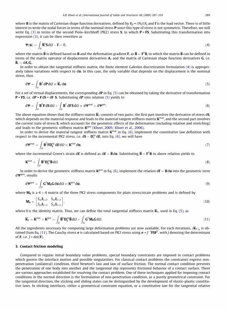
Fig. 2. The double-surface cap plasticity model.
A.R. Khoei et al. / International Journal of Solids and Structures 46 (2009) 287–310 291
where an and at are the normal and tangential penalty parameters, as shown in Fig. 1. Taking the derivative from relation(18), the normal and tangential stiffness matrices at the contact interface are defined as
Kcn ¼ NT
nanNn;
Kct ¼ NT
t atNt:ð19Þ
3.2. Contact friction algorithm
In order to implement the contact constraint of frictional slip, the Coulomb friction law is incorporated in the tangentialspring. According to the numerical procedure described in preceding sections, a computational algorithm is applied based onthe Newton–Raphson technique. For iteration i within the time step n, the following algorithm is performed:
i. Read the incremental displacement of the nodal points.ii. Set the position of ‘slave node’ – ‘master segment’ point.iii. Search those ‘slave nodes’ that are in contact with the ‘master segment’, and determine the values of displacement at
the current time step.iv. Evaluate the stiffness matrices ðKc
n;Kct Þ using appropriate af, and assemble into a global stiffness matrix (at the first
iteration of each time step, set af = at, for subsequent iterations, af is calculated from step ‘ix’ and an is taken as a con-stant value).
v. Solve the global system of equilibrium equation Kitot:d�ui ¼ df i.
vi. Compute the incremental nodal displacement at the next iteration D�ui ¼ D�ui�1 þ d�ui; d�u0 ¼ 0.
DJ2
1J
1fixed yield surface ( )f
ILinePragerDrucker –
01121 =–+–= – αγθ β J
D eJJf
IILinePragerDrucker –
DJ2
1J
TesesTriaxialin
StatesStreesUltimate
ILinePragerDrucker –IILinePragerDrucker –
α
)-( γα
θ 1
a
b
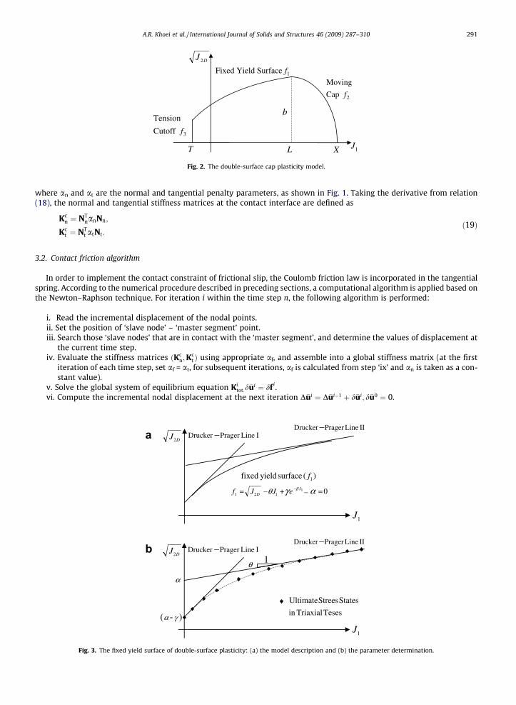
Fig. 3. The fixed yield surface of double-surface plasticity: (a) the model description and (b) the parameter determination.

292 A.R. Khoei et al. / International Journal of Solids and Structures 46 (2009) 287–310
vii. Determine the normal and tangential forces at each slave-master point, in order to modify the value of tangentialforce
DFt ¼ attTmNtD�ui;
DFn ¼ annTmNnD�ui:
ð20Þ
viii. Compute the maximum frictional force based on the Coulomb friction law as
ðDFtÞmax ¼ Cf � lfðDFnÞ; ð21Þ
where Cf and lf are the cohesion and friction coefficient of contact interface.ix. Correct the values of DFt and af if DFt > (DFt)max, according to
TabThe
Fix
a =b =c =h =
af ¼ðDFtÞmax
Dut
�������� and DFt ¼ ðDFtÞmax
Dut
jDutj: ð22Þ
x. Evaluate the out of balance force, or residual force, of contact constraints:
le 1ma
ed s
2250.002000.00
Rn ¼ NTnanNnD�u;
Rt ¼ DFttTmNtD�u:
ð23Þ
Computational algorithm (i)–(x) are repeated until the norm of residual forces and maximum residual are both less thanprescribed tolerance.
4. Powder constitutive model
During compaction, powders exhibit strain or work hardening, the volume reduces and the material becomes harder.In this case, an appropriate constitutive model needs to describe the nonlinear behavior of powders. A number of con-stitutive models for the cold compaction of metal powders have been proposed during last three decades, including:micromechanical models (Fleck, 1995; Ransing et al., 2000) and macromechanical models (Brekelmans et al., 1991;Haggblad and Oldenburg, 1994; Aydin et al., 1996; Khoei and Lewis, 1998, 1999; Khoei et al. 2003–2005). The cone-cap model based on a density-dependent Drucker–Prager yield surface and a non-centered ellipse is developed by Brandtand Nilsson (1999), Gu et al. (2001) and Lewis and Khoei (2001). In the present study, a double-surface cap plasticitymodel, based on a combination of a convex yield surface consisting of a failure envelope and a hardening elliptical
J
J
0 500 10000
25
50
75
100
125
150
175
1
2D1/2
Increase inVolumetric Plastic Strainor Relative Density
Fig. 4. The expansion of moving cap surface with increasing the volumetric plastic strain, or relative density.
terial model parameters for the cap plasticity
urface parameters Cap parameters Tension cutoff
MPa R = 1.75 T = �0.3 MPa2 MPa�1 D = 0.005 MPaMPa W = 0.348 X0 = 1 MPa
A.R. Khoei et al. / International Journal of Solids and Structures 46 (2009) 287–310 293
cap is proposed for the nonlinear behavior of powder materials. The model reflects the yielding, frictional and densifi-cation characteristics of powder along with strain and geometrical hardening which occur during the compactionprocess.
In order to describe the powder behavior during the compaction process, an appropriate constitutive model is employedbased on the double-surface plasticity, as shown in Fig. 2. The model is based on the concept of continuous yielding of pow-ders, expressed in terms of a three-dimensional state of stress and formulated on the basis of consistent mechanics princi-ples. The yield surface of this elasto-plastic model has a moving cap, intersecting the hydrostatic loading line, whose positionis a function of plastic volumetric strain. The main features of the cap model include a failure surface and an elliptical yieldcap which closes the open space between the failure surface and the hydrostatic axis. The cap surface expands in the stressspace according to a specified hardening rule. The functional forms for these surfaces are
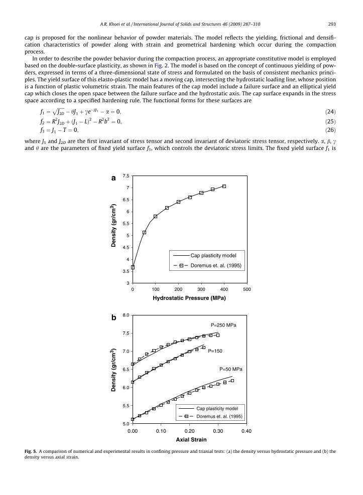
Fig. 5.density
f1 ¼ffiffiffiffiffiffiJ2D
p� hJ1 þ ce�bJ1 � a ¼ 0; ð24Þ
f2 ¼ R2J2D þ ðJ1 � LÞ2 � R2b2 ¼ 0; ð25Þf3 ¼ J1 � T ¼ 0; ð26Þ
where J1 and J2D are the first invariant of stress tensor and second invariant of deviatoric stress tensor, respectively. a, b, cand h are the parameters of fixed yield surface f1, which controls the deviatoric stress limits. The fixed yield surface f1 is
3
3.5
4
4.5
5
5.5
6
6.5
7
7.5
0 100 200 300 400 500
Hydrostatic Pressure (MPa)
Den
sity
(g
r/cm
3 )
Cap plasticity model
Doremus et. al. (1995)
5.0
5.5
6.0
6.5
7.0
7.5
8.0
0.00 0.10 0.20 0.30 0.40
Axial Strain
Den
sity
(g
r/cm
3 )
Cap plasticity model
Doremus et. al. (1995)
P=50 MPa
P=150
P=250 MPa
A comparison of numerical and experimental results in confining pressure and triaxial tests: (a) the density versus hydrostatic pressure and (b) theversus axial strain.

Fig. 6. Plane strain stretching of a thin sheet by a cylindrical punch: the geometry and boundary conditions.
a
b
cFig. 7. Finite element modeling of a thin sheet by a cylindrical punch: (a) initial configuration, (b) deformed mesh at 50% and (c) deformed mesh at 100%.
294 A.R. Khoei et al. / International Journal of Solids and Structures 46 (2009) 287–310

A.R. Khoei et al. / International Journal of Solids and Structures 46 (2009) 287–310 295
defined by an exponential function and in reality is consist of two different Drucker–Prager yield surfaces. The cap yield sur-face f2 is an elliptical function, with R denoting the ratio of two elliptical cap’s diameters. The function f3 indicates the tensioncutoff zone, with T denoting the material’s tension limit.
The hardening rule for moving cap is related to the volumetric plastic strain epv as
XðjÞ ¼ XðepvÞ ¼
�1D
ln1� ep
v
W
� �þ X0; ð27Þ
Fig. 8. Stress distribution contours of a thin sheet by a cylindrical punch at: (a) 50% and (b) 100%.
Dimensionless Displacement U3/L
Pu
nch
forc
e,F
(N/m
m)
0 0.05 0.1 0.15 0.2 0.250
2000
4000
6000
8000
10000
12000
14000
present simulationPeric & Owen (1992)
Fig. 9. Plain strain stretching of a thin sheet by a cylindrical punch: the variation of top punch reaction with vertical displacement.

296 A.R. Khoei et al. / International Journal of Solids and Structures 46 (2009) 287–310
where D and W are material parameters and X0 refers to the position of initial cap surface. The plastic hardening/softeningmodulus H is zero for f1 and f3.
4.1. Material property matrix
In order to compute the powder elasto-plastic constitutive matrix, we need to calculate the plastic hardening/softeningmodulus and flow direction vector in the matrix Dep, defined by
Dep ¼ De � DenQ nTFDe
H þ nTFDenQ
ð28Þ
where De is the elastic constitutive matrix (dre = De de), H is the plastic hardening/softening modulus, nF is the normal vectorto yield surface (oF/or) and nQ is the normal vector to plastic potential surface (oQ/or). The plastic hardening/softening mod-ulus and flow direction vector are defined as
H ¼ � oFoj
� �ojoe
� �T
nQ ; ð29Þ
oFor¼ C1
oJ1
orþ C2
oðJ2DÞ1=2
orþ C3
oJ3D
or; ð30Þ
where C1 = oF/oJ1, C2 ¼ oF=oðJ2DÞ1=2 and C3 = oF/oJ3D.
For the fixed yield surface, the values of constants C1, C2 and C3 in the case of associated flow rule are as follows:C1 ¼ �h� bce�bJ1 , C2 = 1 and C3 = 0. Considering function f2 in Eq. (25) the values of constants Ci for moving cap surfaceare defined as: C1 ¼ ð1=RbÞðJ1 � LÞ, C2 ¼ ð1=bÞR
ffiffiffiffiffiffiJ2D
pand C3 = 0. Finally, the values of constants C1, C2 and C3 for the tension
cut-off yield surface can be simply calculated according to Eq. (26) as C1 = �1.0, C2 = 0 and C3 = 0. The plastic hardening/soft-ening modulus for the fixed yield surface and tension cut-off surface is assumed to be zero. For moving cap surface, the plas-tic modulus H can be obtained by substituting f2 from Eq. (25) into relation (29) as
Fig. 10. The extrusion of an aluminum billet: the geometry and boundary conditions.

Fig. 11.
A.R. Khoei et al. / International Journal of Solids and Structures 46 (2009) 287–310 297
H ¼ � of2
oepv
� �oep
v
oe
� �T
nQ ¼ �of2
oepv
� �ðnQiiÞ; ð31Þ
where
of2
oepv¼ of2
oLoLoep
vþ of2
oboboep
v; ð32Þ
where of2/oL = 2(J1 � L), o f2/ob = �2R2b and
cba
edFinite element modeling of an aluminum billet extrusion: (a) initial configuration, the deformed meshes at (b) 25%, (c) 50%, (d) 75% and (e) 100%.
298 A.R. Khoei et al. / International Journal of Solids and Structures 46 (2009) 287–310
oLoep
v¼ 1
DðW � epvÞ
11þ Rhþ Rbce�bL
; ð33Þ
oboep
v¼ 1
RoXoep
v� oL
oepv
� �: ð34Þ
4.2. Model assessment
In order to evaluate the parameters of double-surface plasticity, it is necessary to obtain these values for the fixed, movingcap and tension cut-off yield surfaces. The fixed yield surface has an exponential form which is composed of an initial portionof the Drucker–Prager envelope joined smoothly to the subsequent Drucker–Prager line, as demonstrated in Fig. 3(a). Theslope of the first Drucker–Prager line, i.e. line I, is grater than the slope of the second Drucker–Prager line, i.e. line II. The logicfor adopting the second Drucker–Prager surface in higher stresses is based on the observation that at higher stresses thematerial behaves like a liquid. This was adopted particularly to simulate behavior of cohesionless materials subjected to highstresses.
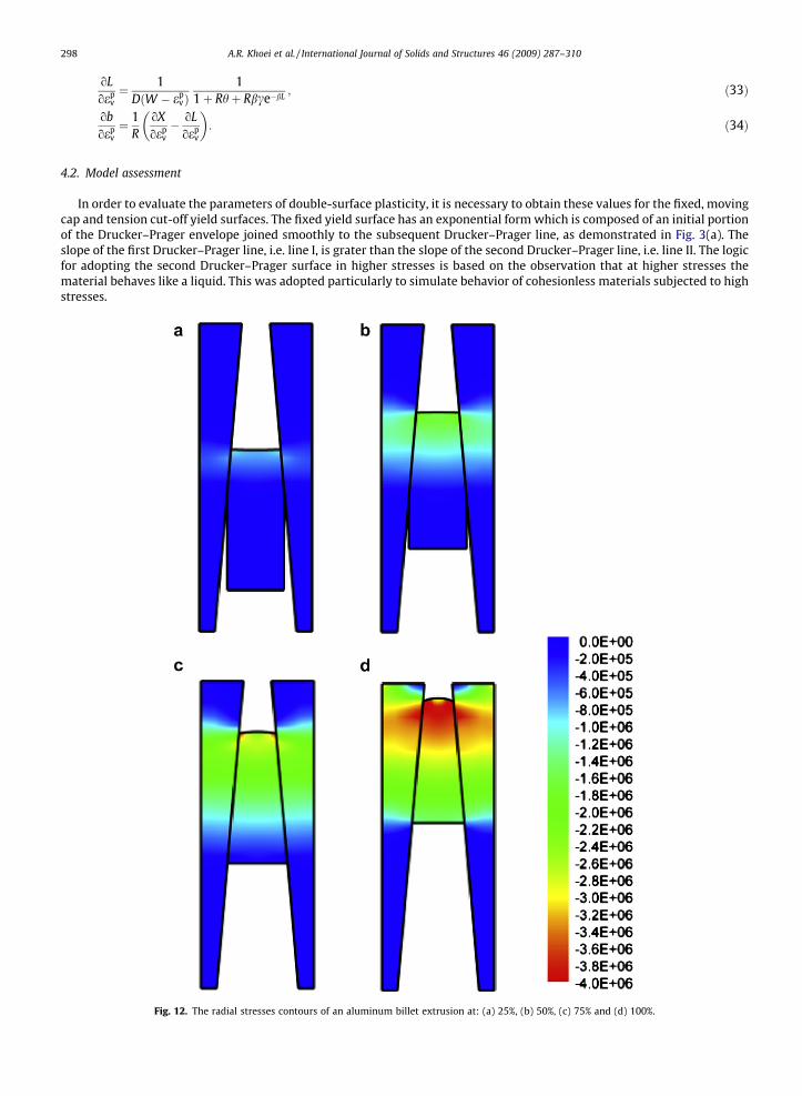
Fig. 12. The radial stresses contours of an aluminum billet extrusion at: (a) 25%, (b) 50%, (c) 75% and (d) 100%.

A.R. Khoei et al. / International Journal of Solids and Structures 46 (2009) 287–310 299
In order to determine the parameters of fixed yield surface f1, the results of triaxial tests are necessary at the ultimateshear stresses. These ultimate points are presented in Fig. 3(b) in J1 �
ffiffiffiffiffiffiJ2D
pplane. Considering the state of stress when J1
is equal to zero and substituting J1 = 0 in Eq. (24) lead to
f1 ¼ffiffiffiffiffiffiJ2D
pþ c� a ¼ 0: ð35Þ
It means that the intersection of the fixed yield surface, or the Drucker–Prager line I, withffiffiffiffiffiffiJ2D
p� axis is a–c. As b is assumed
to be a positive quantity and compression is taken as positive, the quantity of e�bJ1 will be very small for large value of J1.Thus, it leads to
Displacement (cm)
Forc
e (N
)
0 5 10 15 20 25 300
5E+06
1E+07
1.5E+07
2E+07
2.5E+07
3E+07 No frictionFriction coefficient µ=0.1Friction coefficient µ=0.2Padmanabhan & Laursen (2001)
Fig. 13. The variations of vertical force with displacement for an aluminum billet extrusion.
Fig. 14. A plain bush component; the geometry and boundary conditions.

Fig.
300 A.R. Khoei et al. / International Journal of Solids and Structures 46 (2009) 287–310
f1 ¼ffiffiffiffiffiffiJ2D
p� hJ1 � a ¼ 0: ð36Þ
The above equation represents the Drucker–Prager yield criterion, which is shown by line II in Fig. 3. As can be observed theslope of this line is h and its intersection with
ffiffiffiffiffiffiJ2D
p-axis is a. The parameter b in fixed yield surface can be evaluated using an
arbitrary point on transition curve, as shown in Fig. 3(b).In order to determine the parameters of moving cap surface f2, we need to investigate the plastic deformations under
compression. The increase of compression causes the increase of plastic volumetric strain and hence, the expansion ofcap surface in J1-axis. The values of D, W and X0 can be computed by using Eq. (27). The value of X0 is zero when there isno significant initial yielding cap. For granular and porous materials, there is no significant initial stress and X0 = 0. The val-ues of D and W can be obtained from the confining pressure, or hydrostatic pressure test. From these tests, the value of Xobtained by relation (27) is equal to J1. The elastic volumetric strain ee
v can be evaluated from the variation of J1 with ev
on unloading portion curve obtained from the hydrostatic pressure test. The plastic volumetric strains epv can be expressed
in terms of total and elastic components of strain, i.e. epv ¼ ev � ee
v. The values of D and W can be estimated using the variationof J1 and X with ep
v . The parameter R can be determined using the confining pressure and a set of triaxial tests. For the capyield surface with a given value of X, the shape of surface can be specified in J1 �
ffiffiffiffiffiffiJ2D
pplane for the same values of plastic
cba15. Finite element modeling of a plain bush component: (a) initial configuration, (b) deformed mesh at 50% and (c) deformed mesh at 100%.
Top punch vertical displacement (mm)
Top
punc
h ve
rtic
al re
actio
n (N
)
0 1 2 3 4 5 6 7 8 9 10 11 120
20000
40000
60000
80000
100000 No frictionFriction coefficient µ= 0.08Friction coefficient µ= 0.2Experimental (Gethin&Lewis1994)
Fig. 16. A plain bush component: the variations of top punch force with displacement at different friction coefficients.

A.R. Khoei et al. / International Journal of Solids and Structures 46 (2009) 287–310 301
volumetric strain from different hydrostatic and triaxial tests. Fig. 4 shows how the cap yield surface grows with densifica-tion due to increase of the volumetric plastic strain.
4.3. Parameter determination
In order to illustrate the calibration of material parameters in the constitutive model, a sample of metal powder is sim-ulated by fitting the model to reproduce data from isostatic compaction and triaxial compression tests. The experimentaldata are gained from a set of compaction experiments on an iron-based powder (95% by weight) performed by Doremuset al. (1995). Both isostatic compaction and triaxial tests are driven. The raw material is composed of iron, copper, waxand zinc stearate, in which the last two components are admixed as internal lubricants. The density of the solid phase isabout 7.54 g/cm3 and the tap powder density is about 3.67 g/cm3. The particles have irregular shapes and their sizes are be-tween 10 and 100 lm.
The compacted specimen has an initial height of 42 cm and diameter of 20 cm. The triaxial tests consist of an initial iso-static compaction step up to pressure value of 400 MPa, followed by a subsequent uniaxial compaction step. This step is car-ried out by keeping pressure constant and increasing the axial stress up to the maximum value of 1250 MPa. The materialmodel parameters of iron powder for the double-surface cap plasticity are given in Table 1. The initial relative density is
Fig. 17. A shaped-charge liner: (a) geometry and (b) initial FE mesh.
Fig. 18. A shaped-charge liner: the deformed meshes.

Fig. 19. A shaped-charge liner: the distribution of relative density contours at different compaction processes.
Fig. 20. A shaped-charge liner: the distribution of normal stress ry (MPa) contours at different compaction process.
Displacement (cm)
Fo
rce
(kN
)
0 0.2 0.4 0.6 0.8 1-600
-400
-200
0
200
400
600
800
C=0.0,Phi=0.0C=2.0,Phi=2.0C=2.0,Phi=10.0C=2.0,Phi=20.0
Top punch reactions
Bottom punch reactions
c = 0.0 , µ = 0.0c = 2.0 , µ = 0.2 c = 2.0 , µ = 1.0 c = 2.0 , µ = 2.0
Fig. 21. The variations of the punch forces with displacement at different cohesion and friction coefficients.
302 A.R. Khoei et al. / International Journal of Solids and Structures 46 (2009) 287–310

A.R. Khoei et al. / International Journal of Solids and Structures 46 (2009) 287–310 303
�q0 ¼ 0:4 and the Poisson’s ratio is m = 0.3. The variation of the Young modulus with relative density for iron powder is as-sumed as E ¼ 3640�q3:9 (MPa), with �q denoting the relative density (Khoei, 2002).
Fig. 5(a) presents the evolution of the density versus the hydrostatic pressure. This evolution is the characteristic of metalpowders. The experimental and numerical results are compared for the isostatic compression step. The applicability of theproposed cap plasticity to handle the volumetric terms is evident in this figure. Fig. 5(b) corresponds to the complete triaxialcompression tests. The density versus axial strain curves are plotted for different values of the hydrostatic pressure attainedat the end of isostatic compression step. Remarkable agreements between experimental and numerical results are obtained.
Fig. 22. Piercing problem: (a) geometry and (b) initial FE mesh.
Fig. 23. Piercing problem: the deformed meshes.

Displacement (cm)
Displacement (cm)
Fo
rce
(kN
)F
orc
e (k
N)
0 0.2 0.4 0.6 0.8 1 1.2-100
0
100
200
300
400
C=2.0,Phi=0.2C=2.0,Phi=5.0C=2.0,P=10. 0
0 0.2 0.4 0.6 0.8 1-50
0
50
100
150
200
250C=2.0,Phi=0.2C=10.0,Phi=0.2C=15.0,Phi=0.2
Top punch reactions
Bottom punch reactions
Top punch reactions
Bottom punch reactions
c = 2.0 , µ = 0.2 c = 2.0 , µ = 0.5 c = 2.0 , µ = 1.0
c = 2.0 , µ = 0.2 c = 10.0 , µ = 0.2 c = 15.0 , µ = 0.2
Fig. 24. The variations of the top and bottom punch forces with displacement for various contact conditions.
Fig. 25. Piercing problem: the distribution of normal stress ry (MPa) contours at different compaction processes.
304 A.R. Khoei et al. / International Journal of Solids and Structures 46 (2009) 287–310

A.R. Khoei et al. / International Journal of Solids and Structures 46 (2009) 287–310 305
5. Numerical simulation results
In order to illustrate the applicability of the proposed contact friction model together with the large FE deformation andpowder constitutive model presented in preceding sections, the powder behavior during the compaction process of a set ofpowder components are analyzed numerically. The frictional contact algorithm, the elasto-plasticity constitutive matrix ofpowder, and the large deformation formulation, presented in Sections 2–4, have been implemented in a nonlinear finite ele-ment code to evaluate the capability of the model in simulating powder compaction process.
The first two examples, i.e. the plane strain stretching of a thin sheet by a cylindrical punch and the extrusion of an alu-minum billet are chosen to demonstrate the efficiency and accuracy of computational algorithm. Due to significant changesin geometry of components, the capability of proposed technique for handling the large deformation under frictional contactbehavior is verified. The next four simulations are chosen to demonstrate the efficiency and accuracy of computational algo-rithm in the modeling of a set of die-powder pressing, including: a plane bush component, a shaped-charge liner, the pierc-ing problem and spike forming. All numerical examples have been solved under displacement control condition byincreasing the punch movement and predicting the compaction forces at different displacements. The distribution of stressand relative density contours are presented at different stages of compaction. In the FE simulations, the tools are modeled asrigid bodies, because the elastic deformation of the tools has only an insignificant influence on the density distribution in thegreen component.
5.1. Stretching of a thin sheet by a cylindrical punch
The first example is of a plane strain stretching of a thin sheet by a cylindrical punch. This problem is typical for thin sheetmetal forming applications. The geometry and boundary conditions for this example are shown in Fig. 6. The analysis is per-formed employing a 2D representation, restricting the deformations to be symmetric along X1 = 0 and imposing the plane-strain boundary condition in X2-direction. The problem is solved for the final deformed configuration of punch displacementDp = 0.25L and friction coefficient of l = 0.3. The convergence tolerance is set to 10�5 and the total number of 12 incrementsis applied.
Fig. 7 presents the finite element model at initial configuration together with the deformed meshes at 50% and final con-figuration of pressing. The distribution of stress contours in X1-direction is shown in Fig. 8 at the half and final stages ofpressing. This figure clearly presents an appropriate distribution of stresses obtained by imposing the contact constraintsat the contact surface of component and punch. Finally, the diagram of punch reaction force versus vertical displacementis presented in Fig. 9, which can be compared with those reported by Peric and Owen (1992) using the 3D numerical sim-ulation with different punch set up.
5.2. Extrusion of an aluminum billet
The second example is of the extrusion of an aluminum billet, which is applicable typically in metallurgy engineering.This example illustrates the capability of the proposed node-to-surface technique, which can be particularly useful in
Fig. 26. Piercing problem: the distribution of relative density contours at different compaction processes.

306 A.R. Khoei et al. / International Journal of Solids and Structures 46 (2009) 287–310
modeling of contact constraints. Two bodies with frictional surfaces are in contact, large deformations are expected, and con-siderable geometrical nonlinearity behavior is included in the mechanical description. The smoothed and non-smoothed fric-tional contact conditions were proposed by Padmanabhan and Laursen (2001) for this example, and is available forcomparison. Several geometrical complications are included in this problem by inclining the master surface. An efficientsearch algorithm is used for each slave node, which can be easily determined by the relative master segment at differentangle of master segments. The bottom nodes of the billet are subjected to a uniform upward displacement and the outerboundaries of the die are considered fixed. The material properties of the billet are chosen as; K = 63.84 GPa andG = 26.12 GPa. The material properties of the die are chosen so that to ensure significant deformation on both sides of thecontact surface; K = 0.6384 GPa and G = 0.2612 GPa. The Coulomb frictional contact law is used with the friction coefficientof l = 0.2.
In the present simulation, the billet is forced to move upward with the total movement of 300 mm by using an incremen-tal displacement control approach. The initial geometry and boundary conditions are shown in Fig. 10. The finite element
Fig. 28. Spike forming: the deformed meshes.
a b
Fig. 27. Spike forming: (a) geometry and (b) initial FE mesh.
A.R. Khoei et al. / International Journal of Solids and Structures 46 (2009) 287–310 307
model at the initial configuration together with the deformed meshes at 25%, 50%, 75% and final configuration of process aredepicted in Fig. 11. In Fig. 12, the distribution of radial stress contours are shown at different stages of process. The results arein complete agreement with those reported by Padmanabhan and Laursen (2001). Clearly, the maximum compressive stresshappens at the top region of the billet where the contact occurs. In Fig. 13, the variations of vertical force with displacementare shown at different friction coefficients. As can be seen, the force-displacement curve of friction coefficient l = 0.1 is iden-tical with that obtained by Padmanabhan and Laursen (2001).
5.3. A plain bush component
In third example, the uniaxial compaction of a plain bush component, which is extensively used in mechanicalengineering, is modeled numerically. This example is chosen to demonstrate the performance and accuracy of pro-posed computational algorithm for simulation of the frictional contact constraint in powder compaction process.The experimental data reported by Gethin and Lewis (1994) is available for this example and is used for comparison.A cylindrical component of powder with the inner and outer radiuses of 8.5 and 12.5 mm and initial length of20.0 mm has been solved with displacement control by increasing the top punch displacement up to 11 mm whilebottom punch is fixed. The direction of displacement is always in a vertical direction which represents the axialpunch load. The component is made from a mixture of different metallic powders with the material parametersof double-surface plasticity given in Table 1. The die wall friction simulated with the Coulomb friction coefficientsof l = 0.08, 0.1 and 0.3.
The geometry configuration and boundary condition are depicted in Fig. 14. The finite element modeling of bush compo-nent is performed using an axi-symmetric model. The FE model of plain bush at the initial configuration together with thedeformed meshes at the half and final stages of compaction are depicted in Fig. 15. Clearly, it can be seen from the analysisthat the flow pattern is a consequence of two distinct effects. First, the single punch motion gives maximum powder move-ment at the top punch and reduces to zero movement at the bottom punch. Secondly, the effect of friction causes differentpowder movement through the radius of the bush. Finally, the variations of the top and bottom punch forces with displace-ment are plotted in Fig. 16 at different friction coefficients. The result is in good agreement with that reported experimen-tally by Gethin and Lewis (1994) at l = 0.08.
5.4. A shaped-charge liner
The next example is of a shaped-charge liner, which is extensively used for civilian oil and steel sectors in geophysicalprospecting, mining, and quarrying. Most liners used in the civilian sector are often made from a mixture of different metallicpowders. This component has been simulated by Gu et al. (2001) using different punch set up. In the present simulation, ashaped-liner is pressed from the iron powder with the material parameters given in Table 1. The schematic of the process toform a shaped-charge liner from iron powder along with the geometry and initial FE mesh of powder before compaction are
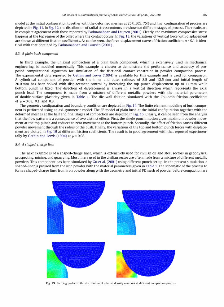
Fig. 29. Piercing problem: the distribution of relative density contours at different compaction process.
308 A.R. Khoei et al. / International Journal of Solids and Structures 46 (2009) 287–310
presented in Fig. 17. The loading characteristics are achieved by the use of prescribed nodal displacements for the top punchmovement. The die and upper punch are modeled as rigid surfaces. The simulation has been performed using the remainingpressing distance of 9.0 mm from above. In Fig. 18, the deformed finite element meshes of the component are presented atfour different stages of compaction.
In Fig. 19, the predicted relative density distributions are shown at different stages of compaction for c = 2.0 MPa andl = 0.2. At the end of the compaction, the relative density contour show that the compaction occurs almost uniform inthe component and the only low region of density appears at the bottom-left corner, which increases gradually to the topand right-hand side of component. In Fig. 20, the results of normal stress ry contours are shown at different stages of com-paction. It is clear from the figure that the effects of cohesion and wall friction cause the lower values of stress at two regions;the bottom-left corner and the top-right corner, which can cause a crack or a reduction of the ultimate strength of the fin-ished compacted component. Finally, the variations of the top and bottom punch forces with displacement are plotted inFig. 21 for different values of cohesion and friction coefficient. This figure clearly shows the effect of cohesion and frictioncoefficient on the punch reactions.
5.5. Piercing problem
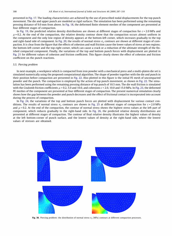
In next example, a workpiece which is compacted from iron powder with a mechanical press and a multi-platen die set issimulated numerically using the proposed computational algorithm. The shape of powder together with the die and punch intheir position before compaction are presented in Fig. 22. Also plotted in this figure is the initial FE mesh of uncompactedpowder and the punch. The compaction is employed by the action of top punch movement, as shown in Fig. 22. The simu-lation has been performed using the remaining pressing distance of top punch of 10.5 mm. The die wall friction is simulatedwith the Coulomb friction coefficients l = 0.2, 5.0 and 10.0, and cohesions c = 2.0, 10.0 and 15.0 MPa. In Fig. 23, the deformedFE meshes of the component are presented at four different stages of compaction. The present numerical simulation clearlyshows how the gap between the powder and punch decreases and the effect of frictional contact is incorporated into accountduring the process of compaction.
In Fig. 24, the variations of the top and bottom punch forces are plotted with displacement for various contact con-ditions. The results of normal stress ry contours are shown in Fig. 25 at different stages of compaction for c = 2.0 MPaand l = 0.2. At the end of the compaction, the contour of normal stress shows the highest stress values at the left part ofcomponent, which reduces gradually to the right-hand side. In Fig. 26, the predicted relative density distributions arepresented at different stages of compaction. The contour of final relative density illustrates the highest values of densityat the left bottom-corner of punch surface, and the lowest values of density at the right-hand side, where the lowestvalues of stresses are obtained.
Fig. 30. Piercing problem: the distribution of normal stress ry (MPa) contours at different compaction processes.

Displacement (cm)
Forc
e (k
N)
0 5 10 15-1500
-1000
-500
0
500
1000
1500
Fx (C=0,Phi=0)Fy (C=0,Phi=0)
Vertical punch reaction
Horizontal punch reaction
Fig. 31. The variations of the vertical and horizontal punch forces with displacement for piercing problem.
A.R. Khoei et al. / International Journal of Solids and Structures 46 (2009) 287–310 309
5.6. Spike forming
The last example demonstrates the performance of present formulation in complicated die geometry and simultaneoushigh distortional and volumetric deformation of elements. In the production of this component the compaction starts fromloose powder by moving the upper punch downward to its final position 16 mm, while the bottom punch is fixed. The sche-matic of the process to form an industrial component along with the geometry and FE meshes of powder and punch beforecompaction are presented in Fig. 27. The loading characteristics are achieved by the use of prescribed nodal displacementsfor the top punch movement. The die and upper punch are modeled as rigid surfaces. The contact friction is simulated usingc = 2.0 MPa and l = 0.2.
In Fig. 28, the deformed FE meshes of the component are presented at four top punch movements. In Figs. 29 and 30, thedevelopment of the normal stress ry and the distributions of relative density of powder are investigated in the compressedcomponent at various stages of compaction. At the end of the compaction, the contours display the lowest values of stressand density at two regions; the top corner and the bottom right-hand side, which increases gradually to the middle part ofcomponent. Finally, the variations of the top punch forces in x- and y-directions are plotted with displacement in Fig. 31 forthe Coulomb friction coefficient l = 0.2 and cohesion c = 2.0 MPa. This example clearly presents the capability of proposedcomputational algorithm in modeling contact friction for large plastic deformation of powder compaction processes.
6. Conclusion
In the present paper, the influence of powder-tool friction was presented in large deformation simulation of powderforming processes. The numerical modeling of frictional contact between a rigid tool and a deformable material was per-formed by the use of a new computational algorithm in the concept of the penalty approach based on the node-to-surfacealgorithm. The frictional properties on the contact surface were performed using a simple and efficient method. A plasticitytheory of friction based on a Coulomb friction law was incorporated to simulate sliding resistance at the powder-tool inter-face. The frictional contact formulation was performed within the framework of large FE deformation in order to predict thenon-uniform relative density distribution during large deformation of powder die pressing. A double-surface cap plasticitymodel was employed for description of powder behavior.
Finally, the capability and efficiency of the proposed contact friction model together with the large FE deformation andpowder constitutive model was presented in numerical modeling of a set of forming processes, including: a plane strainstretching of a thin sheet by a cylindrical punch, the extrusion of an aluminum billet, the compaction process of a plain bushcomponent, a shaped-charge liner, the piercing problem and the spike forming. The distribution of stress and relative densitycontours are presented at different stages of compaction. The results of various contact conditions clearly present the effectof cohesion and friction coefficient at the powder-tooling interface on the punch reaction. The comparisons were performedwith experimental and numerical results reported in literature. The numerical simulation results indicated that the proposedcomputational algorithm makes it possible to simulate the complex phenomena of frictional contact in the powder formingproblems efficiently and accurately.
References
Aydin, I., Briscoe, B.J., Sanliturk, K.Y., 1996. The internal form of compacted ceramic components. A comparison of a finite element modeling withexperiment. Powder Technology 89, 239–254.

310 A.R. Khoei et al. / International Journal of Solids and Structures 46 (2009) 287–310
Beer, G., 1985. An isoparametric joint/interface element for finite element analysis. International Journal for Numerical Methods in Engineering 21, 585–600.
Belyschko, T., Neal, M.O., 1991. Contact-impact by the pinball algorithm with penalty and Lagrangian methods. International Journal for Numerical Methodsin Engineering 31, 547–572.
Benson, D.J., Hallquist, J.O., 1990. A single surface contact algorithm for the post-buckling analysis of shell structures. Computers Methods in AppliedMechanics and Engineering 78, 141–163.
Brandt, J., Nilsson, L., 1999. A constitutive model for compaction of granular media, with account for deformation induced anisotropy. Mechanics ofCohesive Frictional Materials 4, 391–418.
Brekelmans, W.A.M., Janssen, J.D., Van de Ven, A.A.F., de With, G., 1991. An Eulerian approach for die compaction processes. International Journal forNumerical Methods in Engineering 31, 509–524.
Cameron, I.M., Gethin, D.T., 2001. Exploration of die wall friction for powder compaction using a discrete finite element modeling technique. Modeling andSimulation in Materials Science and Engineering 9, 289–307.
Chaudaray, A.B., Bathe, K.J., 1986. A solution method for static and dynamic analysis of contact problems with friction. Computer and Structures 24, 855–873.
Curnier, A., Alart, P., 1988. Generalisation of Newton type methods to contact problems with friction. Journal de Mecanique Theorique et Appliquee 7, 67–82.
Doremus, P., Geindreau, C., Martin, A., Debove, L., Lecot, R., Dao, M., 1995. High pressure triaxial cell for metal powder. Powder Metallurgy 38, 284–287.Ernst, E., Thummler, F., Beiss, P., Arnhold, V., 1991. Friction measurements during powder compaction. Powder Metallurgy International 22, 77–84.Fleck, N.A., 1995. On the cold compaction of powders. Journal of Mechanics and Physics of Solids 43, 1409–1431.Gethin, D.T., Lewis, R.W., 1994. Finite element modeling of powder compaction and its experimental validation. Powder Metallurgy World Congress, Paris,
689–692.Giannakopoulos, A.E., 1989. The return mapping method for the integration of friction constitutive relations. Computers and Structures 32, 157–167.Gu, C., Kim, M., Anand, L., 2001. Constitutive equations for metal powders: application to powder forming processes. International Journal of Plasticity 17,
147–209.Haggblad, H.A., Oldenburg, M., 1994. Modeling and simulation of metal powder die pressing with use of explicit time integration. Modeling and Simulation
in Materials Science and Engineering 2, 893–911.Khoei, A.R., 2002. Numerical simulation of powder compaction processes using an inelastic finite element analysis. Materials and Design 23, 523–529.Khoei, A.R., 2005. Computational Plasticity in Powder Forming Processes. Elsevier, Amsterdam.Khoei, A.R., Azami, A.R., 2005. A single cone-cap plasticity with an isotropic hardening rule for powder materials. International Journal of Mechanical
Sciences 47, 94–109.Khoei, A.R., Azami, A.R., Anahid, M., Lewis, R.W., 2006. A three-invariant hardening plasticity for numerical simulation of powder forming processes via the
arbitrary Lagrangian–Eulerian FE model. International Journal for Numerical Methods in Engineering 66, 843–877.Khoei, A.R., Bakhshiani, A., 2004. A hypoelasto-plastic finite strain simulation of powder compaction processes with density dependent endochronic model.
International Journal of Solids and Structures 41, 6081–6110.Khoei, A.R., Bakhshiani, A., Mofid, M., 2003. An endochronic plasticity model for finite strain deformation of powder forming processes. Finite Elements in
Analysis and Design 40, 187–211.Khoei, A.R., Lewis, R.W., 1998. Finite element simulation for dynamic large elasto-plastic deformation in metal powder forming. Finite Elements in Analysis
and Design 30, 335–352.Khoei, A.R., Lewis, R.W., 1999. Adaptive finite element remeshing in a large deformation analysis of metal powder forming. International Journal for
Numerical Methods in Engineering 45, 801–820.Kim, K.T., Lee, H.T., 1998. Effect of friction between powder and mandrel on densification of iron powder during cold isostatic pressing. International Journal
of Mechanical Sciences 40, 507–519.Laursen, T.A., Simo, J.C., 1993. A continuum-based finite element formulation for the implicit solution of multibody, large deformation frictional contact
problems. International Journal for Numerical Methods in Engineering 36, 3451–3485.Laursen, T.A., Simo, J.C., 1993. Algorithmic symmetrization of Coulomb frictional problems using augmented Lagrangians. Computer Methods in Applied
Mechanics and Engineering 108, 133–146.Lewis, R.W., Khoei, A.R., 2001. A plasticity model for metal powder forming processes. International Journal of Plasticity 17, 1659–1692.Padmanabhan, V., Laursen, T.A., 2001. A framework for development of surface smoothing procedures in large deformation frictional contact analysis. Finite
Element in Analysis and Design 37, 173–198.Peric, D., Owen, D.R.J., 1992. Computational model for 3D contact problems with friction based on the penalty method. International Journal for Numerical
Methods in Engineering 35, 1289–1309.Pietrzak, G., Curnier, A., 1999. Large deformation frictional contact mechanics: continuum formulations and augmented Lagrangian treatment. Computer
Methods in Applied Mechanics and Engineering 177, 351–381.Ransing, R.S., Gethin, D.T., Khoei, A.R., Mosbah, P., Lewis, R.W., 2000. Powder compaction modeling via the discrete and finite element method. Materials and
Design 21, 263–269.Simo, J.C., Wriggers, P., Taylor, R.L., 1985. A perturbed Lagrangian formulation for the finite element solution of contact problems. Computer Methods in
Applied Mechanics and Engineering 51, 163–180.Sinka, I.C., Cunningham, J.C., Zavaliangos, A., 2003. The effect of wall friction in the compaction of pharmaceutical tablets with curved faces: a validation
study of the Drucker–Prager cap model. Powder Technology 133, 33–43.Tabata, T., Masaki, S., Kamata, K., 1980. Determination of the coefficient of friction between metal powder and die wall in compaction. International Journal
of Plasticity 21, 773.Wriggers, P., Simo, J.C., 1985. A note on tangent stiffness for fully nonlinear contact problems. Communications in Applied Numerical Methods 1, 199–203.Wriggers, P., Vu Van, T., Stein, E., 1990. Finite element formulation of large deformation impact-contact problems with friction. Computers and Structures
37, 319–331.
Related Documents