12th North American Waste to Energy Conference May 17-19, 2004, Savannah, Georgia USA NAEC12-2220 ANew Air Compressor Cooling System For The Pinellas County Resource Recovery Facility Thomas M. White, P.E. Regional Engineer Wheelabrator Technologies, Inc. 3001 1l0t h Avenue North Saint Petersburg, FL 33716 Abstract Due to serious deterioration of aluminum fms on two dry coolers only 6 yes aſter initial installation, the potential to disrupt operation of the 3,000 tons per day (tpd) Pinellas County Resource Recovery Facility was a real conce. A new system upgrade was required to provide reliable cooling of the glycol liquid system. This system dissipates the heat rejection requirements of the process and instrument air compressors, particularly critical during Florida's hot sm er months. A second issue was the need to provide redundancy, which was not designed into the original installation. The selected system included two plate and ame coolers along with two pumps located next to the existing cooling tower (C.T.) basin. Water om the C.T. basin is pumped through one plate and ame cooler, reducing the temperature of the glycol liquid. The water then flows back to the C.T. basin. The construction work, completed in August 2003, provides in excess of 200% redundancy and has been in successful operation since that date. 145 Introduction The Pinellas County Waste-To-Energy Facility, located in St. Petersburg, Florida, has a nameplate throughput of 3,000 tons per day (tpd) of processible waste. In May, 2003, the plant celebrated 20 years of continued operation. At ll capacity, the plant can generate 75 MW of electrical energy for sale to Proess Energy Florida, Inc. This power is capable of supplying the electrical needs of 66,000 homes. Over the past 20 years, numerous modifications have been made at the Pinellas facility including the addition of a third 1,000 tpd boiler and 25 MW turbine-generator set in 1985, complete air pollution control (APC) upades in the late 1990s, and major boiler modifications during the early 2000s. As part of the APC upgrade work, an entire new method of providing both process and instrument air was required due to increased air supply demand by the spray dryer absorbers (SDAs) and fabric filters (FFs). A system of air compressors, glycol cooling and dry cooling systems were specified and Copyright © 2004 by ASME

Welcome message from author
This document is posted to help you gain knowledge. Please leave a comment to let me know what you think about it! Share it to your friends and learn new things together.
Transcript
12th North American Waste to Energy Conference
May 17-19, 2004, Savannah, Georgia USA
NAWTEC12-2220
ANew Air Compressor Cooling System For
The Pinellas County Resource Recovery Facility
Thomas M. White, P.E. Regional Engineer
Wheelabrator Technologies, Inc. 3001 1l0th Avenue North
Saint Petersburg, FL 33716
Abstract
Due to serious deterioration of aluminum fms on two dry coolers only 6 years after initial installation, the potential to disrupt operation of the 3,000 tons per day (tpd) Pinellas County Resource Recovery Facility was a real concern. A new system upgrade was required to provide reliable cooling of the glycol liquid system. This system dissipates the heat rejection requirements of the process and instrument air compressors, particularly critical during Florida's hot summer months. A second issue was the need to provide redundancy, which was not designed into the original installation. The selected system included two plate and frame coolers along with two pumps located next to the existing cooling tower (C.T.) basin. Water from the C.T. basin is pumped through one plate and frame cooler, reducing the temperature of the glycol liquid. The water then flows back to the C.T. basin. The construction work, completed in August 2003, provides in excess of 200% redundancy and has been in successful operation since that date.
145
Introduction
The Pinellas County Waste-To-Energy Facility, located in St. Petersburg, Florida, has a nameplate throughput of 3,000 tons per day (tpd) of processible waste. In May, 2003, the plant celebrated 20 years of continued operation. At full capacity, the plant can generate 75 MW of electrical energy for sale to Progress Energy Florida, Inc. This power is capable of supplying the electrical needs of 66,000 homes.
Over the past 20 years, numerous modifications have been made at the Pinellas facility including the addition of a third 1,000 tpd boiler and 25 MW turbine-generator set in 1985, complete air pollution control (APC) upgrades in the late 1990s, and major boiler modifications during the early 2000s.
As part of the APC upgrade work, an entire new method of providing both process and instrument air was required due to increased air supply demand by the spray dryer absorbers (SDAs) and fabric filters (FFs). A system of air compressors, glycol cooling and dry cooling systems were specified and
Copyright © 2004 by ASME
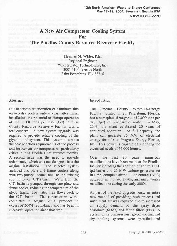
installed at the plant. The dry coolers were installed above the roof of the Air CompressorlMotor Control Center (MCC) room. (See Figure 1.)
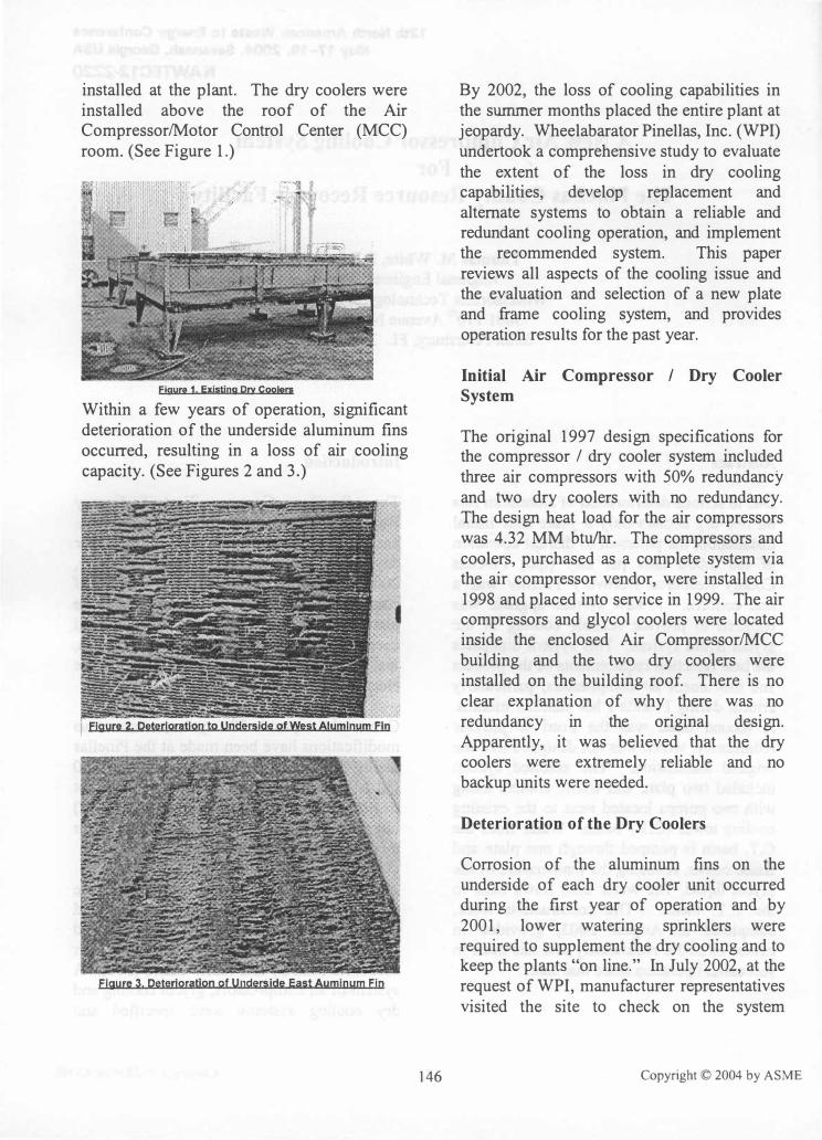
Within a few years of operation, significant deterioration of the underside aluminum fins occurred, resulting in a loss of air cooling capacity. (See Figures 2 and 3.)
146
By 2002, the loss of cooling capabilities in the summer months placed the entire plant at jeopardy. Wheelabarator Pinellas, Inc. (WPI) undertook a comprehensive study to evaluate the extent of the loss in dry cooling capabilities, develop replacement and alternate systems to obtain a reliable and redundant cooling operation, and implement the recommended system. This paper reviews all aspects of the cooling issue and the evaluation and selection of a new plate and frame cooling system, and provides operation results for the past year.
Initial Air Compressor / Dry Cooler System
The original 1997 design specifications for the compressor / dry cooler system included three air compressors with 50% redundancy and two dry coolers with no redundancy. The design heat load for the air compressors was 4.32 MM btu/hr. The compressors and coolers, purchased as a complete system via the air compressor vendor, were installed in 1998 and placed into service in 1999. The air compressors and glycol coolers were located inside the enclosed Air CompressorlMCC building and the two dry coolers were installed on the building roof. There is no clear explanation of why there was no redundancy in the original design. Apparently, it was believed that the dry coolers were extremely reliable and no backup units were needed.
Deterioration of the Dry Coolers
Corrosion of the aluminum fins on the underside of each dry cooler unit occurred during the first year of operation and by 2001, lower watering sprinklers were required to supplement the dry cooling and to keep the plants "on line." In July 2002, at the request of WPI, manufacturer representatives visited the site to check on the system
Copyright © 2004 by ASME

operation and advise on specific deficiencies. Unfortunately, almost 25% of the heat rejection capability of the dry coolers had been lost in only 3 years of operation.
Potential Causes of
Deterioration and
Performance
Aluminum Fin
Dry Cooler
There has been much speculation as to the causes of the deterioration and operation of the dry coolers at the Pinellas facility. They include:
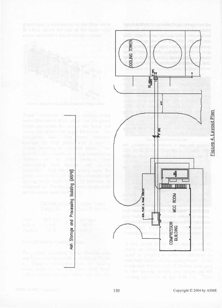
• Water vapors from the five-cell cooling tower (located 160 feet east of the dry coolers) with chlorides and biocides attaching to the aluminum fins. (See Figure 4.)
• Fugitive ash dust emissions from the Ash Processing Building located 140 feet north of the dry coolers (Figure 4) being drawn through the underside of the units, combining with moisture and resulting in fin tube corrosion.
• The plant is approximately 3.5 miles from the salt water of Tampa Bay. Thus, the entire facility is in a highly corrosive environment.
• As shown on Figure 1, there is a 4-foot high parapet wall at the roof of the Air Compressor building. Also, there is limited clearance between the dry coolers and between the header piping and parapet wall. These items may be restricting air flow to the underside of the dry coolers and compromising system performance.
The exact cause(s) of the fin tube corrosion (as well as general deterioration of steel structures in this area of the plant) may never be totally identified. However, it is the opinion of the author that the most significant cause of deterioration has been the water vapor from the cooling tower.
147
Engineering Report by WPI
Subsequent to the vendor's review, WPI prepared a conceptual engineering report for Pinellas County in September 2002. The following four options for correcting the problem were evaluated:
• Option A - Replace existing dry coolers with identical units (20 fans) but with epoxy coating on the fins for corrosion protection.
• Option B - Replace existing dry coolers and add one unit (25 fans) but with epoxy coating on the fins for corrosion protection.
• Option C - Install one new evaporative closed loop cooling system.
• Option D - Install two new plate and frame coolers with cooling water withdrawn and returned to the cooling tower basin.
Options A and B were immediately eliminated since there was no assurance that the thin epoxy coating on the aluminum fins would "hold up" in this environment and the lack of 100% equipment redundancy. Option C was eliminated due to the need to supply· 63 million gallons per year of scarce potable water and the lack of 100% equipment redundancy. Based on the facts that a plate and frame coolers were a sound technical solution and two units would provide 100% redundancy, WPI recommended that Option D be implemented.
Concept of Operation of the Plate and
Frame Coolers
Figure 5 indicates the direction of water flow through a plate and frame cooler. In the Pinellas installation, heat generated from the air compressors is transported via a glycol cooler to the plate and frame unit for temperature reduction. The flow from the
Copyright © 2004 by ASME
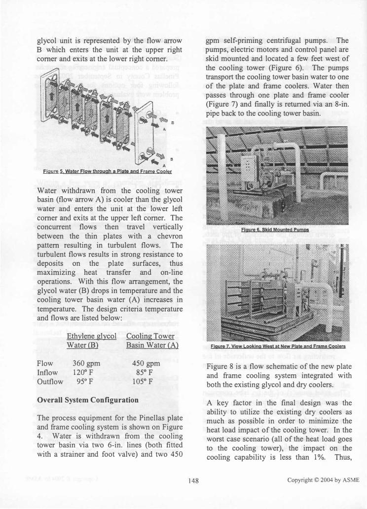
glycol unit is represented by the flow arrow B which enters the unit at the upper right corner and exits at the lower right corner.
B
Figyre 5 Water Flow throygh a plate and Frame Gooier
Water withdrawn from the cooling tower basin (flow arrow A) is cooler than the glycol water and enters the unit at the lower left corner and exits at the upper left corner. The concurrent flows then travel vertically between the thin plates with a chevron pattern resulting in turbulent flows. The turbulent flows results in strong resistance to deposits on the plate surfaces, thus maxmuzmg heat transfer and on-line operations. With this flow arrangement, the glycol water (B) drops in temperature and the cooling tower basin water (A) increases in temperature. The design criteria temperature and flows are listed below:
Ethylene glycol Cooling Tower Water (B) Basin Water CA)
Flow 360 gpm 450 gpm Inflow 120°F 85° F Outflow 95°F 105° F
Overall System Configuration
The process equipment for the Pinellas plate and frame cooling system is shown on Figure 4. Water is withdrawn from the cooling tower basin via two 6-in. lines (both fitted with a strainer and foot valve) and two 450
148
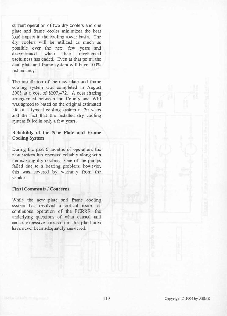
gpm self-priming centrifugal pumps. The pumps, electric motors and control panel are skid mounted and located a few feet west of the cooling tower (Figure 6). The pumps transport the cooling tower basin water to one of the plate and frame coolers. Water then passes through one plate and frame cooler (Figure 7) and finally is returned via an 8-in. pipe back to the cooling tower basin.
Figure 6. Skid Moynted pymps
Figyre 7. View Looking West at New plate and Frame Coolers
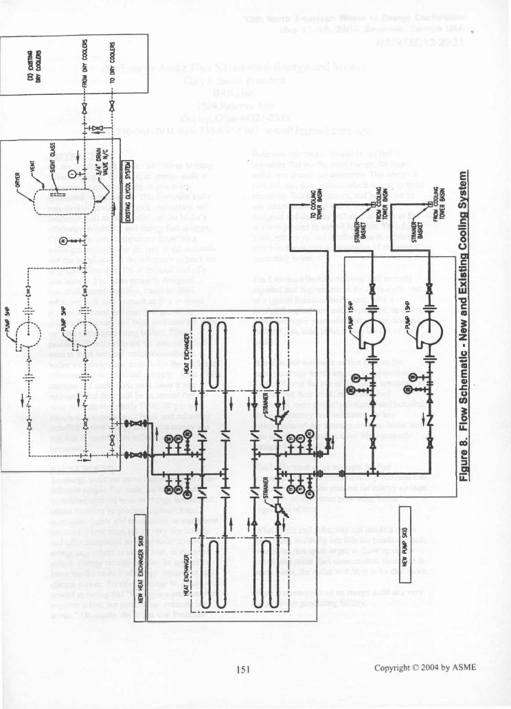
Figure 8 is a flow schematic of the new plate and frame cooling system integrated with both the existing glycol and dry coolers.
A key factor in the final design was the ability to utilize the existing dry coolers as much as possible in order to minimize the heat load impact of the cooling tower. In the worst case scenario (all of the heat load goes to the cooling tower), the impact on the cooling capability is less than 1%. Thus,
Copyright © 2004 by ASME
current operation of two dry coolers and one plate and frame cooler minimizes the heat load impact in the cooling tower basin. The dry coolers will be utilized as much as possible over the next few years and discontinued when their mechanical usefulness has ended. Even at that point, the dual plate and frame system will have 100% redundancy.
The installation of the new plate and frame cooling system was completed in August 2003 at a cost of $207,472. A cost sharing arrangement between the County and WPI was agreed to based on the original estimated life of a typical cooling system at 20 years and the fact that the installed dry cooling system failed in only a few years.
Reliability of the New Plate and Frame
Cooling System
During the past 6 months of operation, the new system has operated reliably along with the existing dry coolers. One of the pumps failed due to a bearing problem; however, this was covered by warranty from the vendor.
Final Comments I Concerns
While the new plate and frame cooling system has resolved a critical issue for continuous operation of the PCRRF, the underlying questions of what caused and causes excessive corrosion in this plant area have never been adequately answered.
149 Copyright © 2004 by ASME
m-e... �
10" C ;;
":3
� CD 0> C a:::: PQi
l.) CII 'III U e ::E
fL. "1:1 C 0::: Q �O CD �� Q) E ec:CI .£ [L:d ::::!::J til oCJ .s::. U �
150 Copyright © 2004 by ASME
VI
...... (") .g �. (JQ
go
<Eil
N
o
o
.j>.
0"
'<: » (/) � tTl
C ••
L."":'
5IfI
0R'fElI
-.,
\. /
;
I '
. ; t r·
····
···-c
"":>·
··�·
· · .. ·
··-1
1 � .•
. �-
.,
···-
1 .. 1'
t···
("'''·
····
' ,
, ,
I
• ,.,
". �
YENT
r ' ....
__ .. #'
'I "
", ,
I ;
I "
i :
i H�
SICHT ClAS
S
(2) EXS1INfl
ORr
COIILEIIS
I L
PUII' 5HP
il
l
a I I
I I
I ,
C" '
-'.
I "
I I
---
. .,.
'\.
4--:
----
11J .•..
•.
_.I',.
.:>···
�·· .
.. ··· ·
J I I. .
........ ..
,' •
••
• � ••
: I � ••
• ( ..
. ,. •••
+.+
... + +
.... ..
l L-
·��
+···
· ·- ·
· I�· J+··
�·+
·FAOIoI DR'I'
COOLERS
't
' '"
t I'
'' �
, t!
I ,
, "
" '..
..' i+�
-h+"""""""""""""�����"""""""'" •
••
••
••
••
••
••
-•
••
••
••
• ��
.��.�
.. .� •
•••
• �
.+.
TO DR'I'
coo.ERS
1 !
C= NEW
Ht:AT EXCIW«iE
R SKO
1
H£AT EXCWoHGE
R lO
T £XtIWGR
r----------:
: _ I: -
:---
---
---
-:
� :
' >1
I -:1<
: :!
--
I .
"
1
-
-
:
i � :
> [ : �
::.�i <
: :!
t.
e.G
_
�151f1
�J 0
ItUT• I
I II
bid
I '
NEW PUMP
SKID
r II
IId -
61SHP
.....
• .fnt.
II
II bid
I'
EXISTINC Cl
¥COl. SYSTDI
TO CO
OUNG TOW£
R MSIN
fROIot COCl
lJNC TOW
ER BASIN
..
....,
FIIOM CO
OUNG TOWE
R BASIN
Figur
e 8.
Flo
w Sc
hem
atic
· Ne
w an
d Ex
istin
g Coo
ling
Syst
em
Related Documents