PERGAMON MATHEMATICAL i%!iLPuTEE MODELLING Mathematical and Computer Modelling 38 (2003) 623-635 www.elsevier.com/lacate/mcm A Network Flow Model of Group Technology L. R. FOULDS Department of Management Systems University of Wail&o Private Bag 3105, Hamilton 2020, New Zealand K. NEUMANN Institute of Economics and Operations Research University of Karlsruhe, Germany (Received September 200.2; accepted January 2003) Abstract-It has long been recognized that productivity in manufacturing plants can often be increased by producing similar products in cells. This involves (i) assigning parts to individual machines, and (ii) forming machines into cells. These two activities have traditionally been carried out separately. However, most solution procedures for (i) above utilize a solution to (ii), and vice versa. Here we present a unified approach that deals with (i) and (ii) simultaneously. The approach is based on a multicommodity circulation minimum cost network flow model with side constraints. @ 2003 Elsevier Ltd. All rights reserved. Keywords-Flexible manufacturing systems, Group technology, Network flow models. 1. INTRODUCTION In 1974, Skinner [l] put forward his concept of a focused factory, in which small manufactur- ing systems operate independently within large production plants. The idea works best for medium-variety, medium-volume situations, that is, batched production. The focused factory is constructed using the notions of either flexible manufacturing systems (FMS) or group technol- ogy (GT), h’ h w 1c are based on the precept that certain activities should be dedicated to a family of related parts in a manufacturing cell. Later, Burbidge [2] developed and popularized a sys- tematic approach to this concept, which has subsequently seen widespread adoption throughout the world. Since machines are located in close proximity in a manufacturing cell, and a family of related parts are produced, there is usually reduction in: transport requirements, conveyance times, setup times, and inventory. Moreover, the relatively large autonomy of these cells leads to extra motivation of the workers (who are responsible for “their products”), often resulting in higher productivity and product quality. These, and other advantages, have been discussed by Shunk [3) and Hadley [4]. However, there are also disadvantages in this approach, such as the relatively costly duplication of machines. FMS is related to GT in so far as both are subsystems that represent “islands” within the production process, consisting of a group of machines (possibly including a material handling 08957177/03/% - see front matter @ 2003 Elsevier Ltd. All rights reserved. doi: 10.1016/S0895-7177103100256-5 Typ-t by .4.&W

Welcome message from author
This document is posted to help you gain knowledge. Please leave a comment to let me know what you think about it! Share it to your friends and learn new things together.
Transcript

PERGAMON
MATHEMATICAL
i%!iLPuTEE MODELLING
Mathematical and Computer Modelling 38 (2003) 623-635 www.elsevier.com/lacate/mcm
A Network Flow Model of Group Technology
L. R. FOULDS Department of Management Systems
University of Wail&o Private Bag 3105, Hamilton 2020, New Zealand
K. NEUMANN Institute of Economics and Operations Research
University of Karlsruhe, Germany
(Received September 200.2; accepted January 2003)
Abstract-It has long been recognized that productivity in manufacturing plants can often be increased by producing similar products in cells. This involves
(i) assigning parts to individual machines, and (ii) forming machines into cells.
These two activities have traditionally been carried out separately. However, most solution procedures for (i) above utilize a solution to (ii), and vice versa. Here we present a unified approach that deals with (i) and (ii) simultaneously. The approach is based on a multicommodity circulation minimum cost network flow model with side constraints. @ 2003 Elsevier Ltd. All rights reserved.
Keywords-Flexible manufacturing systems, Group technology, Network flow models.
1. INTRODUCTION
In 1974, Skinner [l] put forward his concept of a focused factory, in which small manufactur- ing systems operate independently within large production plants. The idea works best for medium-variety, medium-volume situations, that is, batched production. The focused factory is constructed using the notions of either flexible manufacturing systems (FMS) or group technol-
ogy (GT), h’ h w 1c are based on the precept that certain activities should be dedicated to a family of related parts in a manufacturing cell. Later, Burbidge [2] developed and popularized a sys- tematic approach to this concept, which has subsequently seen widespread adoption throughout the world.
Since machines are located in close proximity in a manufacturing cell, and a family of related parts are produced, there is usually reduction in: transport requirements, conveyance times, setup times, and inventory. Moreover, the relatively large autonomy of these cells leads to extra motivation of the workers (who are responsible for “their products”), often resulting in higher productivity and product quality. These, and other advantages, have been discussed by Shunk [3) and Hadley [4]. However, there are also disadvantages in this approach, such as the relatively costly duplication of machines.
FMS is related to GT in so far as both are subsystems that represent “islands” within the production process, consisting of a group of machines (possibly including a material handling
08957177/03/% - see front matter @ 2003 Elsevier Ltd. All rights reserved. doi: 10.1016/S0895-7177103100256-5
Typ-t by .4.&W

624 L. R. FOULDS AND K. NEUMANN
system and workers), which produce a family of items. The main difference between those two systems is that an FMS represents a fully automated system, whereas in GT, conventional technology generally predominates. Most of the recent major results in GT literature have been surveyed by Chu [5], Kusiak and Heragu [6], Vakharia [7] and Wemmerhov and Hyer [S].
Suppose that a number of different products have to be manufactured using certain machine types. It is known from the process plans of the parts which machine types are required for producing the individual parts, and the routing (machine ordering) for each part is given. We wish to assign the different parts to the individual machines of the types required and to group the machines so that each group may form a cell. This requires the following activities to be carried out.
(a) Assign part families to groups of machine types. (b) Find lot sizes of the parts produced. (c) Determine the number of machines needed of each machine type. (d) Assign parts to individual machines. (e) Form machine groups. (f) Compute job schedules for the machines.
The so-called machine type-part incidence matrix specifies which parts are to visit the different machine types. It is desirable that the machine type-part matrix should be transformed into a block-diagonal form to solve Problem (a) (cf. [4,9-111). Each block then shows which family of parts is to be processed on which group of machine types. This process is reviewed in Section 2 of this paper.
If such a block-diagonal clustering cannot be obtained, Activities (b)-(e) above have to be carried out. Well-known methods from inventory control can be used to carry out Activity (b). (cf. (12-151). A method that includes specific information relevant to group technology has been proposed by Askin and Chiu [9]. G iven the lot sizes for all parts, we can compute the utilization of each machine type, which also provides the number of machines needed of each type, that is, allows Activity (c) to be carried out. Activities (b) and (c) are discussed briefly in Section 3 of the present paper.
In the literature, the problems represented by Activities (d)-(f) are generally solved separately. (See, for example, [4,9,10,11,15-221.) Activities (d) and (e) are reviewed in Section 4. However, most solution procedures for Activity (d) utilize a solution to the problem represented by Activ- ity (e) and vice versa. In Section 5, we present a unified approach that deals with Activities (d) and (e) simultaneously.
Activity (f) can be carried out using well-known methods from the literature (cf. [22,23]). Section 7 summarizes our conclusions.
2. FORMATION OF FAMILIES OF PARTS AND THEIR ASSIGNMENTS TO CELLS OF MACHINE TYPES
Assume that n parts, numbered 1,2,. . . , n are processed on m machine types Mr, Mz, . . , Mm, which are to be grouped into cells. The information as to which parts are to visit the individual machine types is given by the so-called machine type-part matrix, with elements:
1, if part j is processed on machine type Mi, and aij :=
0, otherwise(i=1,2 ,..., m,j=1,2 ,..., n). (2.1)
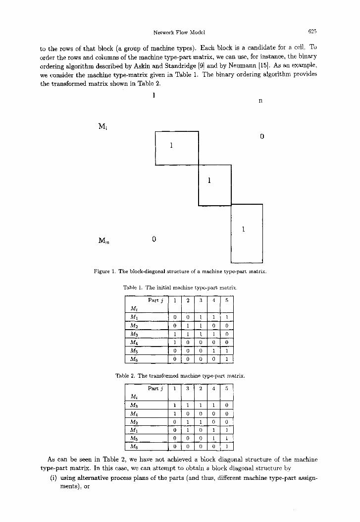
We attempt to reorder the machine type rows and part columns of the machine type-part matrix to obtain a block diagonal structure as shown in Figure 1. The term “block diagonal” implies that we can partition the matrix such that the boxes on the main diagonal contain as many unit entries as possible, but the off-diagonal boxes contain only zero entries. If such a block diagonal structure, as shown, is obtained, the items that correspond to columns of one block (constituting a family of parts) are processed only on those machine types that correspond
Network Flow Model 625
to the rows of that block (a group of machine types). Each block is a candidate for a, cell. TO order the rows and columns of the machine type-part matrix, we can use, for instance, the binary ordering algorithm described by Askin and Standridge [9] and by Neumann [15]. As an example,
we consider the machine type-matrix given in Table 1. The binary ordering algorithm provides the transformed matrix shown in Table 2.
I n
MT”
1
1
1 0
0
Figure 1. The block-diagonal structure of a machine type-part matrix.
Table 1. The initial machine type-part matrix.
Table 2. The transformed machine type-part matrix.
As can be seen in Table 2, we have not achieved a block diagonal structure of the machine type-part matrix. In this case, we can attempt to obtain a block diagonal structure by
(i) using alternative process plans of the parts (and thus, different machine type-part assign- ments), or

626 L. R. FOULDS AND K. NEUMANN
(ii) by assigning a machine type to several families-of parts, or (iii) by forming a smaller number of cells.
(In our example, we assume that grouping all of the machine types is not feasible as the resulting cell is too large.) One alternative is to consider individual machines instead of machine types and to reduce the flow of materials between different cells by a more detailed investigation. The latter possibility is now discussed.
3. COMPUTATION OF LOT SIZES AND MINIMUM NUMBER OF MACHINES
For part j, let dj be the demand per period or unit of time, Kj be the setup cost, and hj be the inventory holding cost per unit and time period. Sometimes the lot size or batch size qj is set as the economic order quantity
qj = 2Kj dj
hj ’ j=1,2 ,..., 71. (34
For formula (3.1), we refer to [12-151. Askin and Chiu [9] h ave modified the economic order quantity cost function by assuming that the total throughput time for a part is a multiple of the total processing time (including setup time) for each lot of that part.
Next, for the individual machine types Mi , Mz, . . . , M,, we determine the minimum number of machines needed. Let Ci be the capacity of a machine of type Mi (measured by its running time including setup) available per period. Let sij be the required setup time per batch or lot of part j for a machine of type Mi (termed an Mi machine), and let tij be the processing time (without setup time) for one unit of part j on an Mi machine. We do not consider conveyance times because they can be neglected within a single GT cell. The processing time pij, of a job j (that is, a batch of size qj of part j) on the Mj machine is then
Pij = Sij + Qjtije
The utilization uij, of machine type Mi by part j is given by
(3.2)
u,. = 3 + djtij. ‘3 3 I
(3.3)
We set uij = 0 if part j is not processed on Mi. The numerator in formula (3.3) represents the running time of machine type Mi per period required for part j. If uij > 1, say, 1 < Uij 5 2, we introduce a dedicated Mi machine to process part j, that will be assigned to the same cell as the first Mi machine that processes part j. Thus, we can assume, without loss of generality, that uij 5 1. That is, one Mi machine is sufficient for processing part j.
Given the utilization uij, of machine type Mi by part j (i < j < n), the minimum number pi, of Mi machines required for producing all parts can be computed as
where ]c] is the smallest integer greater than or equal to c (rounding up). The average utiliza- tion Ci of an Mi machine is
2 Uij j=l
I&=-. Pi
(3.5)
We now go on to use the concepts we have just defined, in the assignment of parts to actual machines.
Network Flow Model
4. MACHINE-PART ASSIGNMENT AND THE GROUPING OF MACHINES
627
If part j is processed on machine type Mi and /.Li > 1, we must specify on which of the /J, machines of type Mi part j is to be manufactured. Thus, for each machine type n/r, with pi > 1, we have to solve a machine-part assignment problem whose objective function (to be minimized) is a measure of the material flow or material handling cost between different cells. In other words, the solving of the machine-part assignment problem requires some preliminary knowledge of the solution to the machine grouping problem.
The machine-part assignment problem can be modelled as a graph-partitioning probkm, where the nodes of the graph correspond to the parts processed on machine type Mi and we seek to determine a minimum cost graph partition into pi subgraphs (cf. [9,15,16]). If pi = 2, and no limits are imposed on the number of nodes of the subgraphs, the graph-partitioning problem can be solved as a multiterminal network flow problem in polynomial time (cf. [23-251). Otherwise, the graph-partitioning problem is known to be NP-hard (cf. [26]). In the machine-part assignment problem, there is a maximum number of parts which can be processed on a single machine of type h/r, due to the limited capacity of that machine. Thus, the corresponding graph-partitioning problem is NP-hard whenever pi > 2.
To reduce the computational effort for solving the graph-partitioning problem, it is recom- mended to use some heuristic method, for example, the Kernighan-Lin heuristic [27], preceded by some partition construction procedure (cf. [15,16]).
The construction procedure determines an assignment of the parts to the machines so that machine capacities are not exceeded. Consider a machine type Mi with pi > 1, and let J,, a subset of {1,2,... ,3}, be the set of parts to be processed on machine type Mi. To construct a feasible solution, assign the parts j (members of Ji) successively to the first Mi machine, with capacity available. If the capacity of the first Mi machine is exceeded, we use a second machine, and proceed analogously. Only if none of the p( machines of type Mi have sufficient capacity to process the entire operation for some part j, do we assume that the operation can be divided into partial operations on several machines.
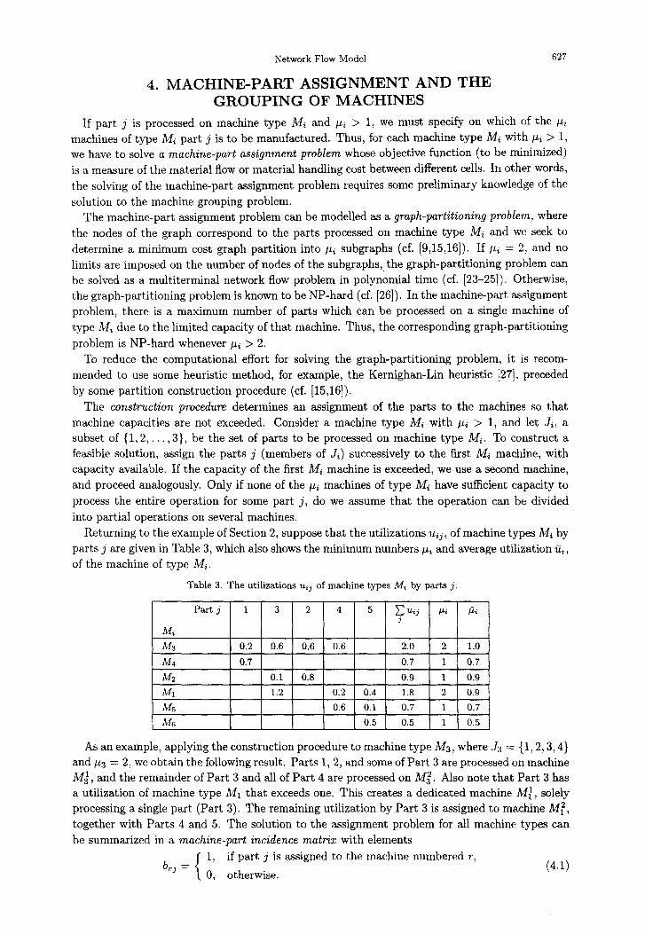
Returning to the example of Section 2, suppose that the utilizations uij, of machine types Mi by parts j are given in Table 3, which also shows the minimum numbers pLi and average utilization cTii, of the machine of type Mi.
Table 3. The utilizations Urj of machine types A4, by parts j.
MS 1 0.5 0.5 1 0.5
As an example, applying the construction procedure to machine type Mz, where Js = { 1,2,3,4} and ~3 = 2, we obtain the following result. Parts 1,2, and some of Part 3 are processed on machine Mj , and the remainder of Part 3 and all of Part 4 are processed on Mi. Also note that Part 3 has a utilization of machine type Ml that exceeds one. This creates a dedicated machine Mt, solely processing a single part (Part 3). The remaining utilization by Part 3 is assigned to machine Mz, together with Parts 4 and 5. The solution to the assignment problem for all machine types can be summarized in a machine-part incidence matrix with elements
brj = 1, if part j is assigned to the machine numbered T,
0, otherwise. (4.1)
628 L. R. FOULDS AND K. NEUMANN
Here, the machine number r stands for some actual machine
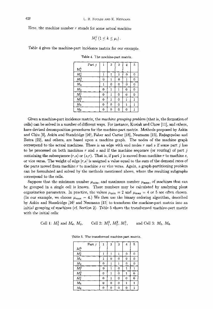
Table 4 gives the machine-part incidence matrix for our example.
Table 4. The machine-part matrix.
Given a machine-part incidence matrix, the machine grouping problem (that is, the formation of cells) can be solved in a number of different ways, For instance, Kusiak and Chow [ll], and others, have devised decomposition procedures for the machine-part matrix. Methods proposed by Askin and Chiu [9], Askin and Standridge [16], Faber and Carter [IS], Neumann [15], Rajagopalan and Batra [22], and others, are based upon a machine graph. The nodes of the machine graph correspond to the actual machines. There is an edge with end nodes r and s if some part j has to be processed on both machines r and s and if the machine sequence (or routing) of part j containing the subsequence (r,s) or (s,r). That is, if part j is moved from machine r to machine s, or vice versa. The weight of edge [r,s] is assigned a value equal to the sum of the demand rates of the parts moved from machine r to machine s or vice versa. Again, a graph-partitioning problem can be formulated and solved by the methods mentioned above, where the resulting subgraphs correspond to the cells.
Suppose that the minimum number pmin, and maximum number pmax, of machines that can be grouped in a single cell is known. These numbers may be calculated by analyzing plant organization parameters. In practice, the values p,in = 2 and pmax = 4 or 5 are often chosen. (In our example, we choose pmax = 4.) We then use the binary ordering algorithm, described by Askin and Standridge [16] and Neumann [15] to transform the machine-part matrix into an initial grouping of machines (cf. Section 2). Table 5 shows the transformed machine-part matrix with the initial cells:
Cell 1: Mj and A44, Mz, Cell 2: M,2, Mi, M:, and Cell 3: J&, Ms.
Table 5. The transformed machine-part matrix.

0 Dl
0 Dl
0 I)?
Network Flow Model
Figure 2. The initial partition into machine groups.
0 JA
0 114
Figure 3. The optimal partition into machine groups
Table 6. The machine sequences (routings) of the parts.
Machine sequences (routings)
To improve this initial grouping, we may again use the Kernighan-Lin heuristic. Figure 2 depicts the weighted machine graph, where we have used the part routings (given by the process plans of the parts), shown in Table 6.
The initial partition is illustrated by vertical lines and each partition set contains dummy nodes (symbol 0) to give each group a maximum number, pmax = 4, of nodes. Each node is associated with the parts processed on the corresponding machine. For example, Parts 1-3 are processed on machine Mj.

630 L. R. FOULDS AND K. NEUMANN
Table 7. The demand rates.
j 1 2 3 4 5
&I412 11214
The demand rates for the example are given in Table 7. Applying the Kernighan-Lin heuristic to the problem represented in Figure 2, we produce the
optimal solution illustrated in Figure 3. The material flows within and between machine groups, that result from Figure 3 and Table 6,
are illustrated in Figure 4. (The dummy machines Dr, D2, Da, and Dq have been omitted.) The arcs are labelled with the respective parts that move along them. We now present a unified approach, in the form of a single model, for the formation of cells, incorporating the assignment of parts to individual machines and the grouping of machines into cells.
35 2
4s
1 Q,
03
Figure 4. The material flows within and between machine groups.
5. A UNIFIED APPROACH TO THE FORMATION OF CELLS We now develop a multicommodity, minimum cost, network circulation flow model for the for-
mation of cells. The nodes in the network in the model can be classified in the following way. The first set of nodes PI, P2, . . . , P, represent the n parts. The second set of nodes Mr, Mz, . . . , M,,, represent the m machine types. An arc is created to joirrdirectly node Pj to node Mi if, and only if, aij = 1. The capacity of this arc is set as
eij = 1. (5.1)
The unit cost of this arc is set as bij = 0. (5.2)
The third set of nodes represent the actual machines, with node Mt representing the lath machine of type Mi, termed machine M/, for i = 1,2,. . . , m, k = 1,2,. . . , pi. For each i, i = 172 ,“., m, an arc is created to join directly node Mi to each node M:. That is, the node for

Network Flow Model 631
each machine of type Mi is joined to the nodes representing the &I.. machines. The capacity of the arc from AL$ to M$ is set as
ef = 1. (5.3)
The unit cost of this arc is set as bf. (54
The fourth set of nodes Br, &, . . . , B, represent the cells that can be formed to group the machines into (up to) p cells. As p is unknown, the following estimate ?j of p is used:
where
AL= [Pmin:Pmsr]. (5.6)
An arc is created to join directly each node Mf to each node B,, i = 1,2,. . , m, k = I> 2,. . , pi, and q = 1,2,. . . ,p. That is, the node of each actual machine is connected to the node of each cell, allowing for the possibility that any machine can be allocated to any cell. The capacity of the arc connecting node M,f to node B, is set as
kq ei
The unit cost of this arc is set as bj” = f(Lj , Kq), where
(5.7)
Lj = the intercell materials handling cost for part j,
K, = the set up cost for the qthcell, and
f (Lj, Kq) = th e combined unit cost incurred, related to Lj and K,
for a single part j being assigned to cell q.
The structure of the network is illustrated in Figure 5.
Figure 5. The structure of the network model.

632 L. R. FOULDS AND K. NEUMANN
The endeavour to minimize the cost of the travel of all flow in this network model is subject to constraints of two types.
(i) Classical network flow constraints: l conservation of flow at all nodes, l arc capacity limits, and l nonnegative flow on all arcs.
(ii) Side constraints: l after any dedicated machines have been removed, each part must be assigned to
exactly one actual machine of each type that is necessary for its processing; l each actual machine must be assigned to exactly one cell; l each cell must be allocated a number of machines between a given lower and upper
bound; l logical links between the utilization variables and the assignment variables must be
observed.
In order to formulate the necessary constraints, we first define some notations.
GIVEN PARAMETERS.
uij = the utilization of machine type Mi by part j (the demand at node Pj).
UTILIZATION DECISION VARIABLES.
x:~ = the utilization of machine type Mi by part j assigned to the actual machine M,“,
Z$ = the utilization of actual machine Ma! by part j that is assigned to the cell q, and
Z: = the total utilization, over all machines, in cell q of part j.
ASSIGNMENT DECISION VARIABLES.
y$J = 1, if part j is assigned to machine M! in cell q,
0, otherwise.
The conservation of flow constraints are as follows. l Conservation of flow at each Ml node.
2 k~fj=e~ij, k=1,2,...,pi, i=1,2, j=l k=l j=l
l Conservation of flow at each Mik node.
~~s$=~LE$, i=l,2 ,..., m, k=1,2, j=l q=l j=l
l Conservation of flow at each B, node.
-&;=g 2 gzz, q=1,2 )..‘) p. j=l i=l j=l hzzl
,m. (5.8)
(5.9) ,I-Li.
(5.10)
l The total machine utilization in all cells equals the total machine utilization of all parts.
f+&j, j=1,2 ,..‘) 72. (5.11) q=l i=l

Network Flow Model
The capacity constraints are as follows. l Each machine JU$ cannot be over-utilized.
12 c x3 51, i= 1,2 ,..., m, k=1,2 ,..., p1. (5.12) j=l
The side constraints are as follows. l After any dedicated machines have been removed, each remaining unassigned part, must be
assigned to exactly one actual machine of each type. That is, its assignment cannot. he split
among more than one actual machine of the same type. A ix Yz”i”, i = 1,2, . . . , m, j=1,2,...,72. q=l h=l
l Each actual machine must be assigned to exactly one cell.
P kc yZ=l, i=1,2 )..., m, ,k=1,2 ,..., pi q=l q=l
(5.13)
(5.14)
l Each cell actually created must contain no less than a given, minimum number of machines.
(5.15)
l If a part j is not assigned to the actual machine M”, then its utilization of that machine must be zero.
,k! < ,“a ZJ - 23 ’ i=1,2 )..., m, j=l,2,...,?& k-1,2 ,..., pi, q=l,&...,P. (5.16)
l The total assignment of parts to each individual machine must not exceed its capacity of one unit. Either a part j is assigned to the ICth individual machine of Type i, which is in cell q, or it is not.
OlXfj 51, i=1,2 )..., m, j = 1,2 ,..., n, k = 1,2 ,... >/I?. (5.17)
Y1”3” E {O,l>, fori=1,2 ,..., m, j=1,2 ,..., n, k=1,2 ,..., pi, qz1.2, . . . . p. (5.18)
The nonnegativity conditions are
xtj 2 0, i=1,2 ,..., m, j=1,2 ,..a, n, k=1,2 ,..., pi. (5.19)
XFQ > 0 23,- ’ i=1,2 I’.., m, j&,2 ,..., n, k=1.2 ,..., pi, q=1,2,...,p. (5.20)
The objective is to
Minimize
subject to the preceding constraints (5.8)-(5.20). This model can be solved for practical numerical instances by the techniques for multicom-
modity network flow models with side constraints given by, among others, Ahuja, Magnanti and Orlin [28].

634 L. R. FOULDS AND K. NEUMANN
6. JOB-SHOP SCHEDULING After the formation of the cells, some job-shop problems have to be solved. A job corresponds
to a lot of some part. For each set of cells, with some intercell material flow (briefly called a cell system), the makespan, that is, the maximum completion time of all jobs, is to be minimized. We seek to determine the job sequence for each machine of the cell system and the job schedules, which specify the start and completion times of the jobs. These job-shop problems can be solved by well-known methods (cf. [29]).
7. SUMMARY AND CONCLUSIONS We have reviewed the issues in the formulation of manufacturing cells assigning parts to indi-
vidual machines and forming individual machines into cells. We have presented a network flow model that combines these two activities in one model. We believe that the resulting multicom- modity network flow model will become a useful tool for production planners.
REFERENCES
1. W. Skinner, The focused factory, Harvard Business Review, 113-121 (May/June 1974). 2. J.L. Burbidge, The Introduction of Group Technology, John Wiley, New York, (1975). 3. D.L. Shunk, Group technology provides an organized approach to realized benefits of CIMs, Industrial
Engineering 17, 74-81 (1985). 4. S.W. Hadley, Finding part-machine families using graph partitioning techniques, ht. J. Prod. Res. 34,
1821-1839 (1996). 5. C.H. Chu, Recent advances in mathematical programming for cell formation, In Planning, Design and
Analysis of Cellular Manufacturing Systems, (Edited by A.K. Kamrani, H.R. Parei and D.H. Liles), pp. 3-46, Elsevier, Amsterdam, (1995).
6. A. Kusiak and S.S. Heregu, Group technology, Computers and Industry 9, 83-91 (1987). 7. A. Vakharia, Methods of cell formation in group technology: A framework for evaluation, J. Operations
Management 6, 257-271 (1993). 8. U. Wemmerlov and N.L. Hyer, Research issues in cellular manufacturing, Znt. J. Prod. Res. 25, 412-422
(1987). 9. R.G. Askin and K.S. Chiu, A graph partitioning procedure for machine assignment and cell formation in
group technology, Znt. J. Prod. Res. 28, 1555-1572 (1990). 10. K.R. Kumar, A. Kusiak and A. Vannelli, Grouping of parts and components in flexible manufacturing
systems, EJOR 24, 387-397 (1986). 11. A. Kusiak and W.S. Chow, Decomposition of manufacturing systems, J. Robotics and Automation 4, 457-471
(1988). 12. F.S. Hillier and G.J. Lieberman, Introduction to Operations Research, McGraw-Hill, New York, (1995). 13. S. Nahmias, Production and Operations Analysis, Second Edition, Irwin, Homewood, IL, (1998). 14. W Domschke, A. Scholl and S. Voss, Productions Planning, Second Edition, Springer-Verlag, Berlin, (1997). 15. K. Neumann, Productions and Operations-Management, Springer-Verlag, Berlin, (1996). 16. R.G. Askin and C.R. Standridge, Modeling and Analysis of Manufacturing Systems, John Wiley, New York,
(1993). 17. Q. Cao and M.A. McKnew, On modelling the design of cellular manufacturing systems, Znt. J. of Flezible
Manufacturing Systems 6, 155-172 (1994). 18. Z. Faber and M.W. Carter, A new graph theory approach for forming machine cells in cellular production
systems, In Flexible Manufacturing Systems: Methods and Studies, (Edited by A. Kusiak), pp. 301-315, Elsevier, Amsterdam, (1986).
19. A. Garcia-Diaz and H. Lee, An industrial application of network-flow models in cellular manufacturing planning, In Planning, Design and Analysis of Cellular Manufacturing Systems, (Edited by A.K. Kamrani, H.R. Parei and D.H. Liles), pp. 47-61, Elsevier, Amsterdam, (1995).
20. S.E. Moussa and M.S. Kamel, Partitioning techniques for cellular manufacturing, In Planning, Design and Analysis of Cellular Manufacturing Systems, (Edited by A.K. Kamrani, H.R. Parei and D.H. Liles), pp. 73-95, Elsevier, Amsterdam, (1995).
21. A. Vannelli and R.G. Hall, An eigenvector solution methodology for finding part-machine families, Int. J. Prod. Res. 31, 325-349 (1993).
22. R. Rajagopalan and J.L. Batra, Design of cellular production systems: A graph-theoretic approach, Znt. J. Prod. Res. 13, 567-579 (1995).
23. R.E. Gomory and T.C. Hu, Multi-terminal network flows, J. SIAM 9, 551-570 (1961). 24. H. Nagamochi and T. Ibaraki, Computing edge-connectivity in multigraphs and capacitated graphs, SIAM
J. Disc. Math. 5, 54-66 (1992).
Network Flow Model 635
25. F. Shahrokhi and D.W. Matula, The maximum concurrent flow problem, J. ACM. 37, 318-334 (1990). 26. M.R. Garey and D.S. Johnson, Computers and Intractability, Freeman, San Francisco, CA, (1979). 27. B.W. Kernighan and S. Lin, An efficient heuristic procedure for partitioning graphs, Bell Systems Technical
Jourml49, 291-307 (1970). 28. R.K Ahuja, T.L. Magnanti and J.B. Orlin, Network Flows, Prentice Hall, Englewood Cliffs, NJ. (1993). 29. M. Pinedo, S&e&ding, Prentice Hall, Englewood Cliffs, NJ, (1995).
Related Documents