ANECHOIC CHAMBER System Design Review 10/14/2011

A NECHOIC C HAMBER System Design Review 10/14/2011.
Dec 19, 2015
Welcome message from author
This document is posted to help you gain knowledge. Please leave a comment to let me know what you think about it! Share it to your friends and learn new things together.
Transcript

ANECHOIC CHAMBERSystem Design Review 10/14/2011
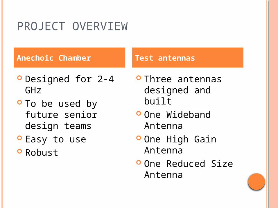
PROJECT OVERVIEW
Designed for 2-4 GHz
To be used by future senior design teams
Easy to use Robust
Three antennas designed and built
One Wideband Antenna
One High Gain Antenna
One Reduced Size Antenna
Anechoic Chamber Test antennas
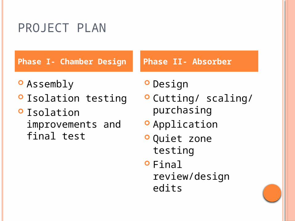
PROJECT PLAN
Assembly Isolation testing Isolation
improvements and final test
Design Cutting/ scaling/
purchasing Application Quiet zone testing Final review/design
edits
Phase I- Chamber Design Phase II- Absorber
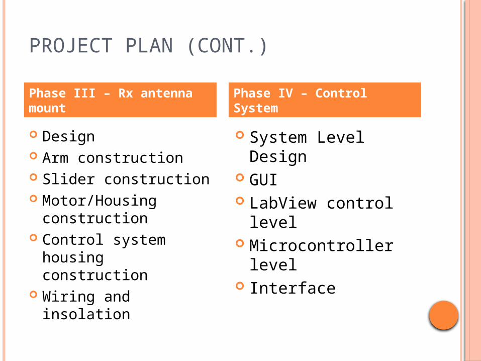
PROJECT PLAN (CONT.)
Design Arm construction Slider construction Motor/Housing
construction Control system
housing construction Wiring and
insolation
System Level Design GUI LabView control
level Microcontroller level Interface
Phase III – Rx antenna mount
Phase IV – Control System
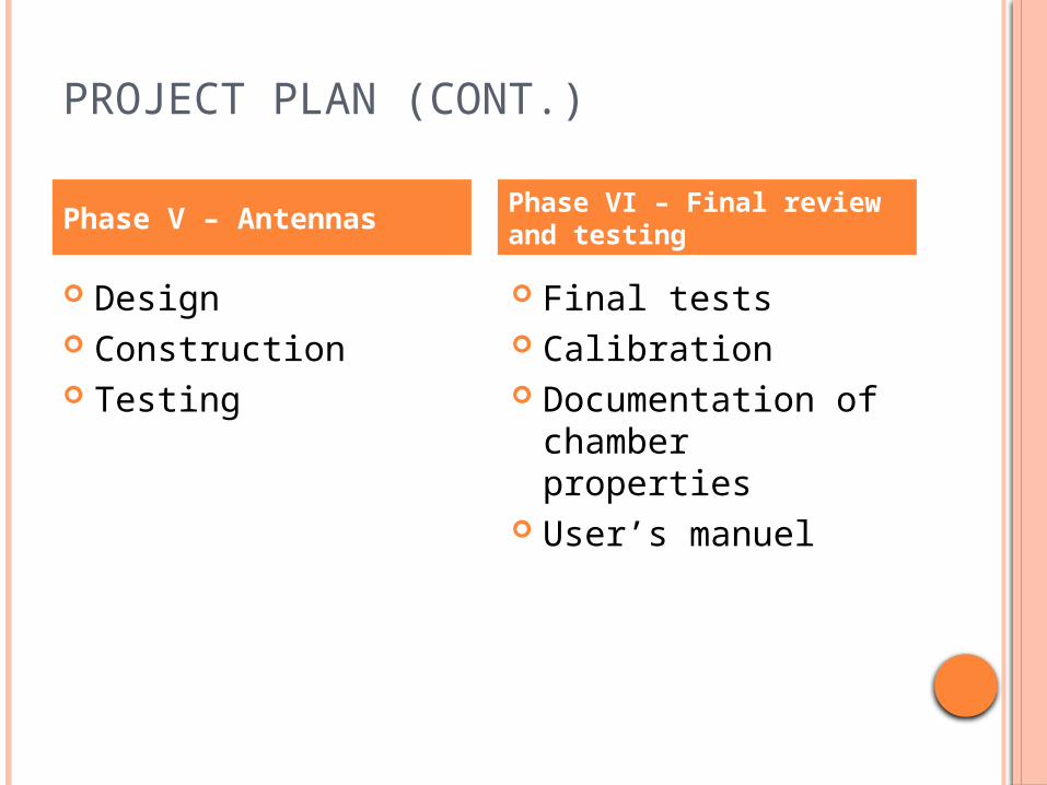
PROJECT PLAN (CONT.)
Design Construction Testing
Final tests Calibration Documentation of
chamber properties User’s manuel
Phase V – Antennas Phase VI – Final review and testing
KEY RISKS
Standard gain reading can not be taken Calibration sequence does not accurately
apply offset so readings are wrong Chamber is too complicated for someone
without RF background to use Absorber is not placed correctly and allows
for reflections

CUSTOMER NEEDS
CUSTOMER SPECIFICATIONS
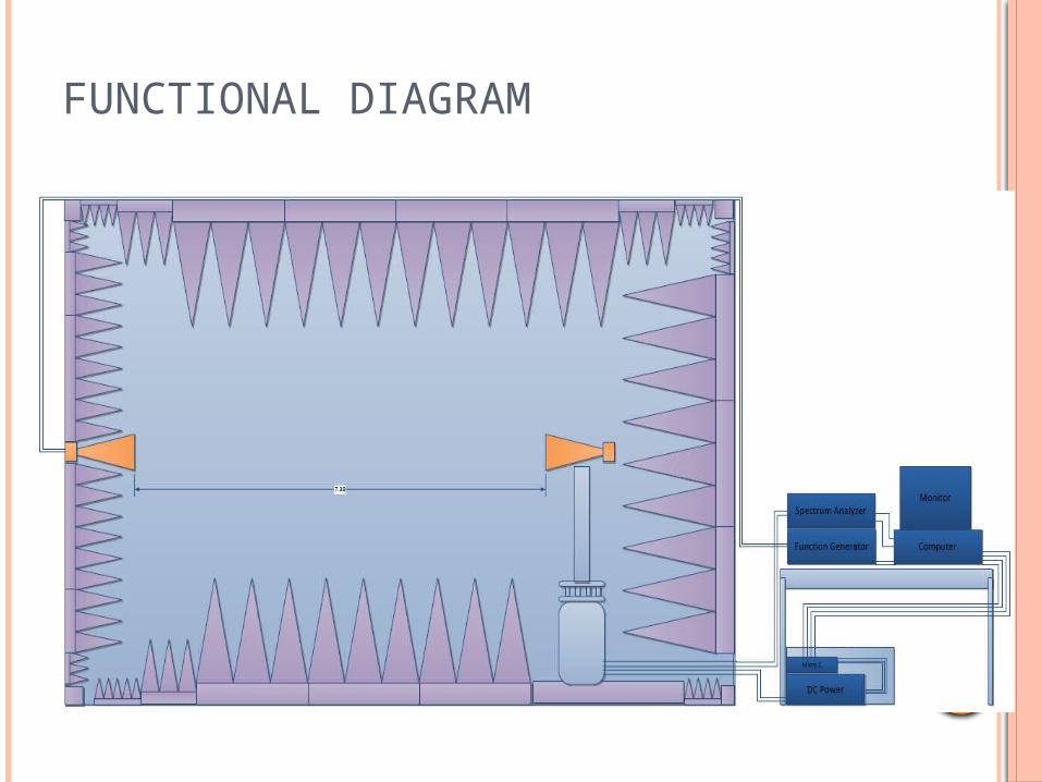
FUNCTIONAL DIAGRAM

ANTENNA MOUNT DESIGN
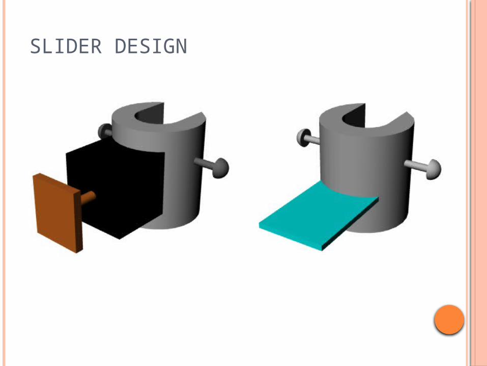
SLIDER DESIGN
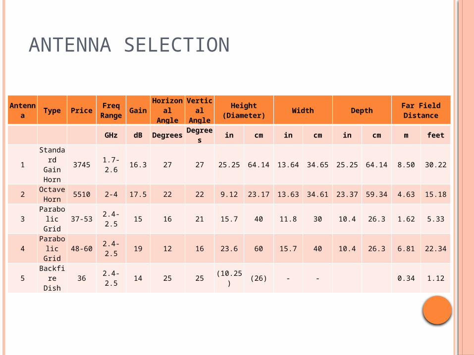
ANTENNA SELECTION
Antenna Type Price Freq Range Gain Horizonal
AngleVertical Angle Height (Diameter) Width Depth Far Field Distance
GHz dB Degrees Degrees in cm in cm in cm m feet
1Standard
Gain Horn
3745 1.7-2.6 16.3 27 27 25.25 64.14 13.64 34.65 25.25 64.14 8.50 30.22
2 Octave Horn 5510 2-4 17.5 22 22 9.12 23.17 13.63 34.61 23.37 59.34 4.63 15.18
3 Parabolic Grid 37-53 2.4-2.5 15 16 21 15.7 40 11.8 30 10.4 26.3 1.62 5.33
4 Parabolic Grid 48-60 2.4-2.5 19 12 16 23.6 60 15.7 40 10.4 26.3 6.81 22.34
5 Backfire Dish 36 2.4-2.5 14 25 25 (10.25) (26) - - 0.34 1.12
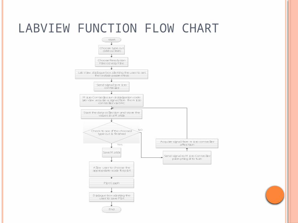
LABVIEW FUNCTION FLOW CHARTstart
Choose type cut (180 or 360)
Choose Resolution Fine or very Fine
Send signal to micro controller
Micro Controller run initialization code lab view acquire a signal from the micro
controller via DAC
Start the data collection and store the values in a Matrix
Lab View dialogue box alerting the user to set the certain parameters
Check to see if the choosed type cut is finished
Save Matrix
Allow user to choose the appropriate scale for plot
Plot Graph
Dialogue box alerting the user to save Plot
End
Yes
NO
Send signal to Micro Controller prompting it to turn
Acquire signal from micro controller after trun
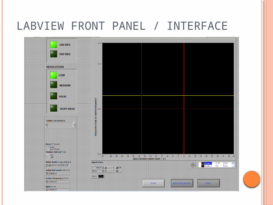
LABVIEW FRONT PANEL / INTERFACE
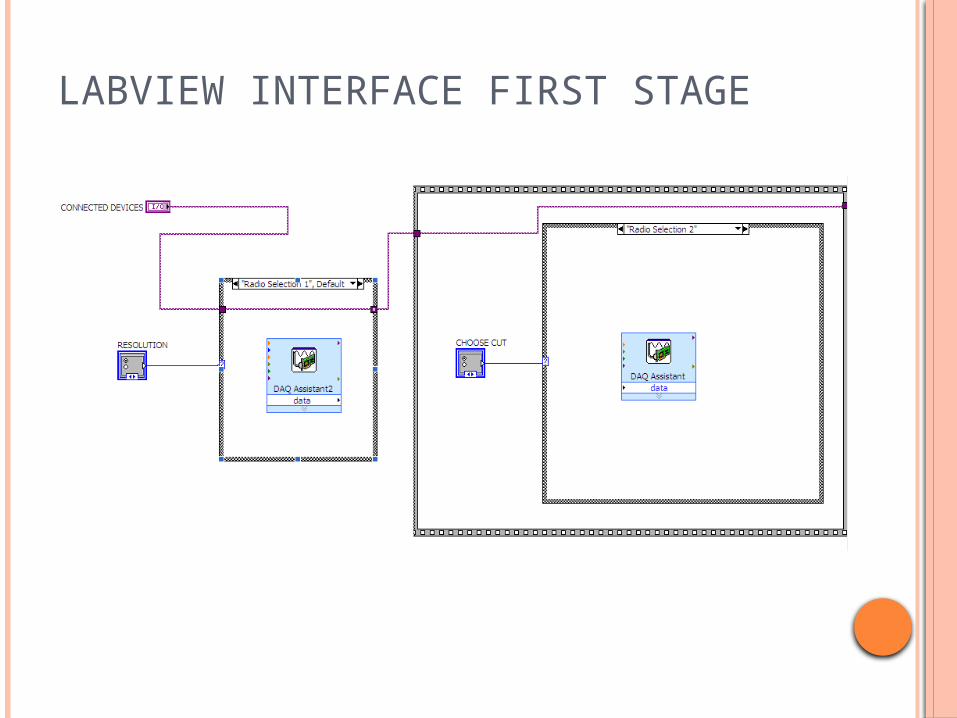
LABVIEW INTERFACE FIRST STAGE
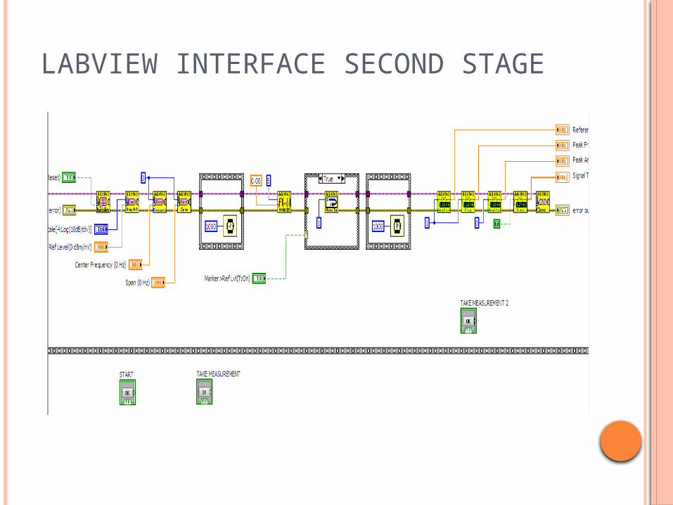
LABVIEW INTERFACE SECOND STAGE

LABVIEW INTERFACE THIRD STAGE

CONTROL SYSTEM DIAGRAM
Linear flow Micro Controller
interfaces with LabView
Reset option for users to stop program mid-execution
When normal execution completes, exports all data to a text file to be used with programs such as Matlab
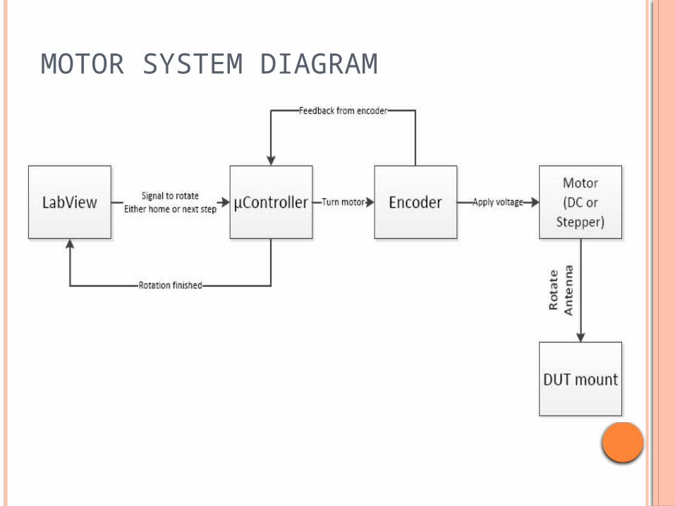
MOTOR SYSTEM DIAGRAM
Related Documents


![Gauge invariance in simplicial gravityaeneas.ps.uci.edu/hamber/gauge.pdf · 346 H.W Hamber, R.M. Williams~Nuclear Physics B 487 (1997) 345-408 [4]. One would hope that a number of](https://static.cupdf.com/doc/110x72/5fc6b201d5d9c43b634318fd/gauge-invariance-in-simplicial-346-hw-hamber-rm-williamsnuclear-physics-b-487.jpg)