A Mold Simulator for the Continuous Casting of Steel: Part I. The Development of a Simulator A. BADRI, T.T. NATARAJAN, C.C. SNYDER, K.D. POWERS, F.J. MANNION, and A.W. CRAMB Surface defects, such as oscillation marks, ripples, and cracks that can be found on the surface of continuously cast steel, originate in the continuous casting mold. Therefore, a detailed knowledge of initial solidification behavior of steel in a continuous casting mold is necessary because it determines the surface quality of continuously cast slabs. In order to develop an understanding of the initial solid- ification of continuous cast steels, a “mold simulator” was designed and constructed to investigate heat-transfer phenomena during the initial phase of strand solidification. The mold simulator was used to obtain solidified steel shells of different grades of steel under conditions similar to those found in industrial casting operations. The resulting cast surface morphologies were compared with industrial slabs and were found to be in good agreement, indicating that it is possible to simulate the continuous casting process by a laboratory scale simulator. I. INTRODUCTION ONE of the difficulties in studying the effects of oper- ational parameters on the initial solidification behavior of steel in a continuous casting mold is the interdependence among different variables. It is not always feasible to con- duct controlled experiments on an industrial continuous caster that will allow the effects of different operational parame- ters on the initial solidification of steel to be studied due to practical constraints. Therefore, most of the information developed on the formation of defects during the continu- ous casting of steels is collected under uncontrolled condi- tions. In the past, this constraint has led to the development of different types of mold simulators to study various aspects of continuous casting. Mold simulators can generally be divided into four types— dip tests, static molds, dip simulators, and small-scale cast- ers. The major issue in designing mold simulators is to ensure that the apparatus and the experiment are a true simulation of reality. This has led to the development of experiment- specific simulators that simulate the conditions in a casting mold to different degrees. For example, to study the effects of mold fluxes on the heat transfer between steel and a copper mold, Machingawuta et al. [1] developed a dip-type simulator specifically for that purpose. Another dip-type sim- ulator was used by Bouchard et al. [2] to investigate the effects of mold surface conditions on the heat-transfer rate and atten- dant surface quality of the cast product. These dip simula- tors involved chilled plates that were immersed into a molten metal bath without any of the sophistication of continuous caster systems, such as oscillation and shell extraction. The dip simulators are very useful for determining fundamental interactions in the continuous casting process, but are not true simulators since they do not mimic the dynamic nature of continuous casting. Related to the dip test simulators are the bottom-pouring molds, which are in essence similar to dip-type mold sim- ulators, with the exception that the bottom-pouring simulators have the metal contained in the mold, instead of having the mold dipped into the metal. This configuration has the advan- tage that it is easier to observe the surface of the casting during solidification. Tomono et al. [3] used a bottom-filling mold to investigate the behavior of the liquid steel meniscus during casting and projected the results to explain the for- mation of oscillation marks. Wray [4] developed a simulator to determine the mechanisms by which surface features formed on chill cast surfaces and provided a classification of the different types of features that could be formed. Stemple et al. [5] used a bottom-pouring configuration to investigate the formation of ripple marks on the surfaces of continuously cast products. It was emphasized that the bot- tom-pouring simulator could only be used to investigate phe- nomena unrelated to mold oscillation, since the experimental apparatus did not have provision for oscillation. Even so, Stemple et al. were able to observe the motion of the menis- cus and provided an explanation for the formation of ripple marks. Nishida et al. [6] developed a mold simulator with the novel addition of an in-situ tool to measure the distortion of the shell from the mold wall. This was done to determine the dynamics of air gap formation and the resulting effect on the steel-mold heat transfer. Again, these were incom- plete simulators of the continuous casting process. To incorporate further sophistication into the experiment, several researchers have constructed more complex dip-type experiments in which the mold is equipped with oscillation drives and a mechanism for the extraction of the solidified shell to simulate continuous casting. This type of mold sim- ulator is quite versatile and has been used by Saucedo [7] to investigate the initial solidification phenomena. The simu- lated castings exhibited the typical surface morphologies of industrial cast slabs, and the results were used to propose a mechanism of oscillation mark formation. The work also included a comprehensive survey of the various hypotheses METALLURGICAL AND MATERIALS TRANSACTIONS B VOLUME 36B, JUNE 2005—355 A. BADRI is with Shell Oil, Malaysia. T.T. NATARAJAN, Senior Research Engineer, C.C. SNYDER, Senior Technician, and K.D. POWERS, Project Analyst, are with the U.S. Steel Research and Technology Center, Monroeville, PA 15140. F.J. MANNION, General Manager, is with U.S. Steel, Slovakia. A.W. CRAMB is with the Department of Metallurgical and Materials Engineering, Carnegie Mellon University, Pittsburgh, PA 15213. Contact e-mail: [email protected] Manuscript submitted February 4, 2004.

Welcome message from author
This document is posted to help you gain knowledge. Please leave a comment to let me know what you think about it! Share it to your friends and learn new things together.
Transcript

A Mold Simulator for the Continuous Casting of Steel:Part I. The Development of a Simulator
A. BADRI, T.T. NATARAJAN, C.C. SNYDER, K.D. POWERS, F.J. MANNION, and A.W. CRAMB
Surface defects, such as oscillation marks, ripples, and cracks that can be found on the surface ofcontinuously cast steel, originate in the continuous casting mold. Therefore, a detailed knowledge ofinitial solidification behavior of steel in a continuous casting mold is necessary because it determinesthe surface quality of continuously cast slabs. In order to develop an understanding of the initial solid-ification of continuous cast steels, a “mold simulator” was designed and constructed to investigateheat-transfer phenomena during the initial phase of strand solidification. The mold simulator was usedto obtain solidified steel shells of different grades of steel under conditions similar to those found inindustrial casting operations. The resulting cast surface morphologies were compared with industrialslabs and were found to be in good agreement, indicating that it is possible to simulate the continuouscasting process by a laboratory scale simulator.
I. INTRODUCTION
ONE of the difficulties in studying the effects of oper-ational parameters on the initial solidification behavior ofsteel in a continuous casting mold is the interdependenceamong different variables. It is not always feasible to con-duct controlled experiments on an industrial continuous casterthat will allow the effects of different operational parame-ters on the initial solidification of steel to be studied due topractical constraints. Therefore, most of the informationdeveloped on the formation of defects during the continu-ous casting of steels is collected under uncontrolled condi-tions. In the past, this constraint has led to the developmentof different types of mold simulators to study various aspectsof continuous casting.
Mold simulators can generally be divided into four types—dip tests, static molds, dip simulators, and small-scale cast-ers. The major issue in designing mold simulators is to ensurethat the apparatus and the experiment are a true simulationof reality. This has led to the development of experiment-specific simulators that simulate the conditions in a castingmold to different degrees. For example, to study the effectsof mold fluxes on the heat transfer between steel and acopper mold, Machingawuta et al.[1] developed a dip-typesimulator specifically for that purpose. Another dip-type sim-ulator was used by Bouchard et al.[2] to investigate the effectsof mold surface conditions on the heat-transfer rate and atten-dant surface quality of the cast product. These dip simula-tors involved chilled plates that were immersed into a moltenmetal bath without any of the sophistication of continuouscaster systems, such as oscillation and shell extraction. Thedip simulators are very useful for determining fundamental
interactions in the continuous casting process, but are nottrue simulators since they do not mimic the dynamic natureof continuous casting.
Related to the dip test simulators are the bottom-pouringmolds, which are in essence similar to dip-type mold sim-ulators, with the exception that the bottom-pouring simulatorshave the metal contained in the mold, instead of having themold dipped into the metal. This configuration has the advan-tage that it is easier to observe the surface of the castingduring solidification. Tomono et al.[3] used a bottom-fillingmold to investigate the behavior of the liquid steel meniscusduring casting and projected the results to explain the for-mation of oscillation marks. Wray[4] developed a simulatorto determine the mechanisms by which surface featuresformed on chill cast surfaces and provided a classificationof the different types of features that could be formed.Stemple et al.[5] used a bottom-pouring configuration toinvestigate the formation of ripple marks on the surfaces ofcontinuously cast products. It was emphasized that the bot-tom-pouring simulator could only be used to investigate phe-nomena unrelated to mold oscillation, since the experimentalapparatus did not have provision for oscillation. Even so,Stemple et al. were able to observe the motion of the menis-cus and provided an explanation for the formation of ripplemarks. Nishida et al.[6] developed a mold simulator with thenovel addition of an in-situ tool to measure the distortion ofthe shell from the mold wall. This was done to determinethe dynamics of air gap formation and the resulting effecton the steel-mold heat transfer. Again, these were incom-plete simulators of the continuous casting process.
To incorporate further sophistication into the experiment,several researchers have constructed more complex dip-typeexperiments in which the mold is equipped with oscillationdrives and a mechanism for the extraction of the solidifiedshell to simulate continuous casting. This type of mold sim-ulator is quite versatile and has been used by Saucedo[7] toinvestigate the initial solidification phenomena. The simu-lated castings exhibited the typical surface morphologies ofindustrial cast slabs, and the results were used to propose amechanism of oscillation mark formation. The work alsoincluded a comprehensive survey of the various hypotheses
METALLURGICAL AND MATERIALS TRANSACTIONS B VOLUME 36B, JUNE 2005—355
A. BADRI is with Shell Oil, Malaysia. T.T. NATARAJAN, SeniorResearch Engineer, C.C. SNYDER, Senior Technician, and K.D. POWERS,Project Analyst, are with the U.S. Steel Research and Technology Center,Monroeville, PA 15140. F.J. MANNION, General Manager, is with U.S.Steel, Slovakia. A.W. CRAMB is with the Department of Metallurgicaland Materials Engineering, Carnegie Mellon University, Pittsburgh, PA15213. Contact e-mail: [email protected]
Manuscript submitted February 4, 2004.

356—VOLUME 36B, JUNE 2005 METALLURGICAL AND MATERIALS TRANSACTIONS B
Fig. 1—Schematic sketch of liquid steel in a continuous caster mold.
proposed in the literature for oscillation mark formation.Suzuki et al.[8] designed simulation experiments on shell for-mation and mold flux consumption and also presented find-ings on the formation mechanism of oscillation marks. Thesesimulators simulated the dynamic nature of continuous cast-ing but were not true simulators of the heat-transfer condi-tions that could be found in the steel plant.
The next step in complexity of mold simulators was tobuild a scale model of an actual continuous casting machine,with the liquid contained in the mold. These mold simula-tors include various levels of the complexity found in indus-trial machines, and are generally used as pilot casters toinvestigate particular conditions that cannot be studied withany of the previous simulators or even on an actual caster.One of the earliest reported experiments was that of Savageand Pritchard,[9] who built a mold to investigate billet rup-ture during continuous casting. Singh and Blazek[10] con-structed a similar model to study the effects of heat transferand shell formation on surface rippling in low-carbon steels.Building further on this idea, and to determine the variousfactors affecting mold heat transfer, Blazek et al.[11] built asimulator that had mold plates modified to allow for varia-tions in the water cooling flow configuration. To investigatethe effects of high oscillation frequencies on oscillation marksand mold flux consumption, Yasunaka et al.[12] constructeda simulator with a modified oscillation drive that allowedthe mold to be oscillated at frequencies up to 50 Hz. Toillustrate the importance of using a simulator instead of anactual casting machine, the authors found that a danger withhigh-frequency oscillation is that there exists the possibil-ity that resonance can occur, leading to catastrophic failureof the machine.
The state of the liquid steel meniscus is often consideredto be important in the formation of oscillation marks, but itis exceedingly difficult and dangerous to attempt to observethe liquid steel meniscus directly in an industrial caster. Toattempt visual observation, Matsushita et al.[13] constructeda simulator with a quartz window near the meniscus. Theexperiments yielded important information on the distortionof the meniscus during the oscillation cycle as affected bythe casting speed. In another effort to improve the surfacequality of continuously cast slabs, Itoyama et al.[14] builta simulator with horizontal oscillation in addition to the com-monly utilized vertical oscillation, and found that the depthof oscillation marks decreased with the use of horizontaloscillation.
In order to conduct comprehensive studies on the effectsof operational parameters on casting quality, it is often nec-essary that the casting parameters be varied independentlyof each other. With this goal in view, a dip-type simulatorof a continuous caster was developed in this study, withcapabilities for mold oscillation and continuous shell extrac-tion, and with the cooling conditions and capacity that arefound in industrial casting machines. The mold simulatordeveloped in this study is unique in the geometric form ofthe mold and in the sophistication of the sensor instrumen-tation. Additionally, this study used sensor configurationsthat were optimized to detect small changes in temperatureand displacement in the system. The main objective of thisarticle is to present a description of the system and severalexamples of useful data that can be obtained during a nor-mal trial, including subsecond temperature variations, heat
fluxes related to initial solidification, and surface profiles.Using these experimental data, the validity of hypotheses ofoscillation mark formation can be tested. The simulationcapability of the mold simulator itself was verified by obtain-ing solidified shells of different grades of steel under con-ditions that would be commonly seen in industrial operations.The surface quality of the simulated shells was then com-pared against that of industrial slabs to ensure reproducibility.It is shown that the mold simulator does indeed replicate thesurface features seen in a slab cast under industrial conditions.
II. EXPERIMENTAL TECHNIQUE
Figure 1 is a schematic of the molten steel in a continu-ous casting mold. The mold is cooled by water flowingthrough the grooves and acts as a heat sink. The steel solid-ifies against the copper mold and increases in thickness asit moves down the length of the mold. The steel shell isabout 12 mm in thickness when it exits the mold. The moldis oscillated to prevent the sticking of the steel shell to thecopper mold, and this oscillation promotes the infiltrationof a film of liquid flux between the shell and the mold. Fur-thermore, the liquid mold flux on top of the liquid steel solid-ifies where it contacts the copper mold and gradually buildsup a flux/slag rim. It has been theorized that the oscillationof the copper mold is responsible for the formation of oscil-lation marks.[3]
A mold simulator provides an ideal laboratory system forthe study of initial solidification of steel in a continuouscasting mold. The depth and width of the oscillation markscan be easily modified by changing the mold oscillationcycle, oscillation stroke, and casting speed. In addition, theeffects of different mold fluxes on the initial heat transfercan be studied easily without interrupting the normal pro-duction operations at the plant.

METALLURGICAL AND MATERIALS TRANSACTIONS B VOLUME 36B, JUNE 2005—357
(a)
(b)
Fig. 3—The copper mold assembly and extractor mechanism.Fig. 2—Schematic sketch of the mold simulator stage.
Mold Simulator
The mold simulator developed in this study is an inverse-type mold, where the steel solidifies around the mold, insteadof the mold surrounding the solidifying steel. Figure 2 is aschematic sketch of the mold simulator stage, which con-sists of several distinct modules to simulate the castingprocess.
The different physical modules of the simulator includethe mold assembly, the extraction mechanism, the stabi-lization system, and the oscillation mechanism. The moldassembly consists of a pair of grooved copper plates and astainless steel baffle that separates the inlet and outlet water,as shown in Figure 3. In this work, the mold surface is flatinstead of cylindrical, and is constructed from actual moldplates previously used at the U.S. Steel Gary Works. Thisflat plate configuration has nickel plating on the hot face,and the cold face is grooved with cooling channels. Figure 4shows the assembly of a typical mold used in the mold sim-ulator and the placement of the stainless steel baffle thatallows the circulation of cooling water. The assembled partsare Tungsten inert gas (TIG)-welded to form a unit, afterwhich the unit is pressurized with water and checked forleaks. Figure 5 shows the dimensions of the copper platesand of the cooling grooves. Figure 5 also shows the locationof the meniscus with respect to the bottom of the mold andthe locations of thermocouples with respect to the meniscus.
The cooling water is fed into the mold from the coolingwater manifold, as shown in Figure 2.
In order to simulate continuous casting, the mold assem-bly is fitted with an extraction mechanism, which is fabri-cated from 6.25-mm-thick steel plates. The extractor pullsthe solidifying steel shell in the casting direction (down-wards). This exposes liquid steel to the water-cooled cop-per mold at the meniscus and allows the formation of a newsteel shell. The extractor is designed so that only one face

358—VOLUME 36B, JUNE 2005 METALLURGICAL AND MATERIALS TRANSACTIONS B
Fig. 4—Steps in building the mold assembly.
of the mold is exposed to the liquid steel, as seen in Fig-ure 3. This allows a controlled exposure of the mold hotface to the liquid steel while protecting the other faces ofthe mold.
The process of solidification and extraction of the steelshell displaces some liquid steel, and so the stabilization sys-tem moves the main stage upward with time to maintain theliquid steel meniscus at a constant level (about 150 mm fromthe bottom) with respect to the copper mold. All of thesensor systems, data and control cables, and drive systemsare protected from the steel bath by a heat shield.
The mold is connected to an oscillating stage so that themold oscillates sinusoidally in the vertical direction aboutthe meniscus position. A slotted cam is used to convert therotational motion of the motor into a linear vertical sinu-soidal oscillation of the rectangular mold. The extractor isattached to drive shafts powered by stepper motors. Duringthe experiment, the drive shafts push the steel shell downwith respect to the meniscus and expose steel to the coppermold to allow the formation of “new” steel shell. The moldmotion is independent of the extractor motion. This allowsthe incorporation of negative strip time, which can be defined

METALLURGICAL AND MATERIALS TRANSACTIONS B VOLUME 36B, JUNE 2005—359
Fig. 5—Dimensions of mold copper plate with thermocouple locations(dimensions in millimeters). Note: The oval shown at the right is not exactlythe same as that shown at the left.
as the portion of the mold oscillation cycle during which themold moves downward faster than the shell. The translat-ing stage is controlled so that the meniscus remains about150 mm from the bottom of the mold during an experiment.
In order to characterize the heat transfer, the mold wasinstrumented with thermocouples to observe the transientvariation of the temperature and heat flux during the cast-ing period. The instrumentation of the mold with thermo-couples was preceded by a comprehensive study[15] oftemperature measurements in conducting solids. For exam-ple, it is known that when a temperature sensor is insertedinto a conducting solid, the void created for the sensor and thesensor material itself can introduce errors into the measuredtemperature signal. These errors were studied to determinehow best to install the sensors in the mold. Additionally, theresponse of the material, as deduced from the temperaturesensors, was studied under conditions of transient high ther-mal fluxes to determine the ability of the sensor to dis-criminate between different functional forms of surface heatflux variation. A heat-transfer simulator was also used toconfirm the ability of subsurface thermocouples to measuresmall variations in temperature due to oscillations in the sur-face heat flux. The resulting conceptual models assisted inthe development of a greater understanding of meniscus heattransfer, which finally led to the ability to interpret the heat-transfer data obtained from the mold simulator experiments.
A heat flux simulator was built that allowed heat fluxesof up to 1 MW/m2 to be applied to a copper mold. A varietyof thermocouple designs were modeled to determine the opti-mum method to allow transient heat fluxes to be measuredaccurately. This study allowed such issues as hole size, posi-tioning, thermocouple attachment, and data acquisition tech-
niques to be fully developed before application on the moldsimulator.
Based on the preceding heat-transfer studies, the moldwas instrumented with 12 grounded T-type thermocouplesat various elevations to detect casting events on the hot faceof the mold. The thermocouples were arranged in twocolumns—1.5 and 5.0 mm from the hot face—of six rows.The six rows were in the immediate vicinity of the aimmeniscus location of 150 mm. Figure 5 shows the physicallocations of the thermocouples with respect to the menis-cus. These thermocouples are located 133, 140, 146, 152,159, and 165 mm from the bottom of the mold. The moldswere machined with 1.59-mm-diameter � 50-mm-deep ther-mocouple voids with an orientation parallel to the mold sur-face to install the thermocouples. The dual-lead T-typethermocouples used in the experiments have magnesiumoxide insulation and a stainless steel sheath with an outerdiameter of 0.5 mm. The thermocouples were fitted withmetal collars to ensure a good fit in the void so that the posi-tions of the tips were well defined, and the tips were cov-ered with a heat sink compound to enhance heat transfer tothe thermocouple tip. In addition to the thermocouples, lin-ear velocity displacement transducers (LVDTs) were usedto monitor the motions of the mold and the extractor mech-anism. By attaching both LVDTs to the same reference point,motions of the extractor and mold were measured relativeto the same frame of reference. The instrumentation of themold resulted in a complete characterization of heat-transferphenomena with respect to the motion of the mold. TheNational Instruments Labview software was used to acquiretemperature data at 60 Hz for the duration of the experimentto detect phenomena occurring within individual oscilla-tion cycles.
The temperature data acquired from the mold thermo-couples were used to develop an estimate of the heat fluxthrough the mold during the initial solidification of the steelshell using the one-dimensional inverse heat conduction pro-gram developed by Beck.[16] A typical form of the physicalproblem which Beck’s method is designed to solve is shownin Figure 6. It is sufficient to use only one internal body
Fig. 6—Physical description of the problem domain.

360—VOLUME 36B, JUNE 2005 METALLURGICAL AND MATERIALS TRANSACTIONS B
Fig. 7—Problem domain including two thermocouples.
Fig. 8—Domain decomposition yielding a known value boundary condition.
temperature and one boundary condition to determine theunknown boundary condition.
In the mold simulator experiments, the known boundarycondition is the convective cooling of the mold by waterflowing through cooling channels. While there are correla-tions for determining the heat-transfer coefficient for thecooling channels, another thermocouple was introduced intothe domain to provide a well-defined boundary condition.The domain of the problem shown in Figure 7 can be decom-posed into two domains by creating an interface S at the sec-ond thermocouple. The boundary condition at this pointS then applies to the two subdomains. This decompositionis shown in Figure 8. In this case, the first thermocouplewas 1.5 mm away from the heated surface, while the second
thermocouple 5.0 mm away from the heated surface wasused to define the subdomain.
Before using this program and the domain decompositionapproach to calculate heat fluxes from experimental data,the reliability of the program was tested rigorously usingdata from simulations. This was done to ensure that the pro-gram would calculate results that were accurate and precisefor the waveforms of interest in this work, and to examinethe effects of the known boundary conditions and signalnoise. For more details, interested readers can refer to thework of Badri.[15]
III. EXPERIMENTAL PROCEDURE
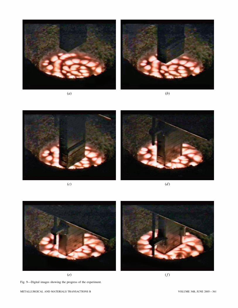
A typical experimental run of the mold simulator involvesthe heating and melting of a charge of ultra-low carbon steelin a 200-kg induction furnace under an argon atmosphere.After the charge is molten, the chemistry and temperatureof the melt are adjusted to aim values and enough mold fluxpowder is added to the surface so that there will be a layerof molten flux approximately 6.5-mm thick on top of theliquid steel after melting. Following the melting of the moldflux powder, the levels of the liquid steel and mold slag aremeasured to ensure that the meniscus will be located at aparticular level on the mold (150 mm from the bottom ofthe mold). Samples of the steel and slag are taken for analy-sis, and then the liquid steel is heated to slightly above thedesired casting temperature. When the aim temperature isreached, the main stage is lowered into the steel bath (Fig-ures 9(a) through (c)). During the descent of the main stage,the oscillator motor is turned on. After the main stage reachesa preset depth (Figure 9(d)), it is held for 3 seconds to forman initial shell on the mold. This pause allows for the for-mation of a shell sufficiently strong to prevent tearing of theinitial steel shell during extraction. In the casting phase (Fig-ure 9(e)), the extractor is lowered an additional 3 in. atconstant velocity while the mold continues to oscillate aboutthe meniscus to simulate the continuous casting of a 3-in.length of steel shell. The main stage moves to compensatefor any additional displacement of the liquid level so thatthe meniscus is maintained at the same level with respect tothe mold. At the end of the casting phase (Figure 9(f)), theentire assembly is withdrawn from the furnace and the shellis allowed to cool (Figures 9(g) through (i)). The profile ofthis motion is shown in Figure 10(a), while the correspondingvelocity profile is shown in Figure 10(b).
Additional samples of the liquid steel and mold flux aretaken to analyze for any change in composition. After theshell has completely cooled, the portion of the shell thatsolidified adjacent to the copper mold is cut away. Figure 11shows a schematic sketch of a cutaway shell from a typicalmold simulator run. The solidified shell is removed fromthe mold while an attempt is made to keep the mold fluxfilm intact on the mold surface. As an example, the shellsurface from an ultra-low carbon grade casting is shown inFigure 12. The shell is shown just after it was removed fromthe mold. Good slag infiltration between the copper moldand the steel shell can be seen. Subsequently, the surfaceprofile is measured along the centerline of the steel shell,corresponding to the location of the thermocouples in themold, using a contact profilometer.
METALLURGICAL AND MATERIALS TRANSACTIONS B VOLUME 36B, JUNE 2005—361
(b)
(c) (d )
(e)
(a)
( f )
Fig. 9—Digital images showing the progress of the experiment.

362—VOLUME 36B, JUNE 2005 METALLURGICAL AND MATERIALS TRANSACTIONS B
(g) (h)
(i)
Fig. 9—(Continued). Digital images showing the progress of the experiment.
(a) (b)
Fig. 10—Mold and steel shell displacement and velocity during an experiment.

METALLURGICAL AND MATERIALS TRANSACTIONS B VOLUME 36B, JUNE 2005—363
Fig. 11—Schematic sketch of an expected steel shell from a mold simu-lator run.
ate the differences between different grades of steel. Fur-thermore, the shells obtained from mold simulator runs arecompared with industrial samples. This is an important stepbecause it reveals whether the cast shells are in fact repre-sentative of industrial cast slabs. The surface profile of thesolidified steel shell can be analyzed in conjunction with themeasured temperatures to obtain insight into the solidifica-tion history of the shell surface. Such an analysis is the maintopic of a subsequent article.[17]
Typical temperature traces, as recorded by thermocouplesjust above and below the meniscus, are shown in Figure 13.The thermocouples below the meniscus measure higher tem-peratures because of the direct contact of the mold surfacewith the liquid steel, and they also register the variations intemperature due to mold oscillation. The temperature tracesmeasured by all of the thermocouples have roughly the sameform. The initial temperature of the mold is ambient tem-perature. As the mold is immersed into the liquid steel bath,the temperature rises. However, as the mold enters the bathand the liquid steel begins to solidify on the hot face, thereis also an increase in the resistance to further heat transfer,which results in a decrease in the temperature measured bythe thermocouples. During the extraction phase of the cast-ing process, the temperature rises as the mold is exposed tofresh liquid steel at the meniscus, and the oscillation in tem-perature reflects the changing position of the mold withrespect to the meniscus. At the end of the casting stage, themold is withdrawn from the liquid steel and the thermo-couples show a rapid decrease in mold temperature.
Figure 14 shows typical temperature traces measured byall of the thermocouples during the casting stage of an ultra-low carbon grade of steel. The labels 5.25F, 5.25B, etc. referto the locations of thermocouples. The numeric value denotesthe distance of the thermocouple from the bottom of the mold
Fig. 12—Example of a mold flux film (left) and steel shell (right) from an ultra-low carbon steel trial.
IV. RESULTS AND DISCUSSION
Using the mold simulator, experimental runs were con-ducted for several grades of steel with most of the runsfocused on ultra-low carbon steel. Table I summarizes thetypical chemical composition for the experimental runs, whileTable II summarizes the operating parameters. Some of thetypical information that can be obtained during the opera-tion of the mold simulator includes temperature history, theassociated heat flux at the hot face of the mold, the surfaceprofile of the cast shell measured using a contact pro-filometer, and flux film characteristics.
The surface profiles of ultra-low, peritectic, and medium(hyperperitectic) carbon steels are shown below to enumer-

364—VOLUME 36B, JUNE 2005 METALLURGICAL AND MATERIALS TRANSACTIONS B
Table I. Typical Chemical Compositions
Ultra-Low Peritectic MediumElement Carbon Steel Steel Carbon Steel
Pct carbon 0.0046 0.065 0.175Pct manganese 0.46 0.95 1.17Pct silicon 0.11 0.22 0.31Pct sulfur 0.0089 0.0075 0.027Pct nitrogen 0.0057 0.0047 0.0069
Table II. Operating Parameters
Stroke (mm) 6.3Oscillation frequency (Hz) 1.3Casting/extraction speed (mm/s) 12.7
Fig. 13—Thermocouple temperature traces during immersion and castingof steel using the mold simulator.
in inches, while the character (F or B, meaning front or back)refers to the distance of the thermocouple tip from the hotface. The F refers to thermocouple tips located about 1.5 mmfrom the hot face, while B refers to the thermocouple tipslocated 5.0 mm from the hot face. It can be seen that theindividual oscillations in temperature due to the oscillationof the mold relative to the meniscus have been resolved. Thetrials indicate that any phenomenon causing a temperature
change greater than �0.1 °C can be identified with the currentthermocouple instrumentation of the mold.
Figure 15 shows a close-up view of the temperature datarecorded by the thermocouples at the meniscus, from whichthe associated heat flux at the meniscus shown in Figure 16is derived using the one-dimensional inverse heat conductionprogram developed by Beck. The heat flux plotted is thehorizontal heat flux in the area of the meniscus and is notthe total heat removed from the steel in the meniscus area.In the meniscus area, the heat flux is multidimensional andtransient. Calculation of multidimensional heat conductionusing inverse techniques is a very complicated issue and itsdiscussion is beyond the scope of this work. Figure 16 andsubsequent plots are shown to illustrate that heat fluxes inthe meniscus area can be measured and that, even in theone-dimensional solution, one can adequately resolve tran-sient behavior in the heat flux during the oscillation cycle.In this study, unfiltered and unaltered heat flux data calcu-lated directly from thermal measurement are shown. It isfelt that other methods of calculation of heat flux would onlychange the numbers and not the variation of the heat fluxvalues as a function of oscillation cycle.
An image of the surface of the ultra-low carbon steel shelland the associated contact profile measurement are shown inFigure 17. From the surface profile measurement, it can be
Fig. 14—Mold thermocouple data during the casting stage of an ultra-lowcarbon steel grade.
Fig. 15—Temperatures measured by thermocouples at the meniscus dur-ing solidification of an ultra-low carbon steel grade.
Fig. 16—The heat flux calculated using the temperature data from the ther-mocouples at the meniscus during solidification of an ultra-low carbon steelgrade.

METALLURGICAL AND MATERIALS TRANSACTIONS B VOLUME 36B, JUNE 2005—365
seen that this grade of steel has peaks that are rounded betweenoscillation marks. Furthermore, the oscillation marks in theultra-low carbon grade can be described as being composedof peaks and subpeaks. In other words, each oscillation markis bracketed by these sharp peaks, and within each oscillationmark, there is an irregularity referred to here as a subpeak.
Figures 18 through 20 show the temperature and heat fluxgraphs for the peritectic grade of steel. Figure 21 is a con-tact profile measurement of the surface of the steel shell castby the mold simulator. The surface profile measurementindicates that this particular grade of steel has several plateau-
shaped features between oscillation marks and that the shapeof the oscillation marks is sharply defined.
Figures 22 through 24 show the variation of temperatureand heat flux values during the course of an experiment for
(b)
(a)
Fig. 17—(a) Photograph and (b) measured profile of shell surface for anultra-low carbon steel grade.
Fig. 18—Mold thermocouple data during casting stage of a peritectic steelgrade.
Fig. 19—Temperatures measured by thermocouples at the meniscus dur-ing solidification of a peritectic steel grade.
Fig. 20—The heat flux calculated using the temperature data from the ther-mocouples at the meniscus during solidification of a peritectic steel grade.

366—VOLUME 36B, JUNE 2005 METALLURGICAL AND MATERIALS TRANSACTIONS B
a medium carbon (hyperperitectic) grade of steel. Finally,Figure 25 shows the measured surface profile of a mediumcarbon steel shell from the mold simulator experiment. Thisgrade exhibits poorly defined peaks and relatively smoothplateaus. It was found that the geometry of the oscillationmarks in medium carbon steel appears to be a function ofthe mold flux used. The morphologies of the oscillationmarks for ultra-low carbon, peritectic, and medium carbonsteel grades are summarized in Figure 26.
From the heat flux graphs, it can be seen that the totalheat flux at the meniscus can be considered as the sum of
an average baseline component and a time-varying compo-nent. The time-varying component of the heat flux has amagnitude approximately 10 pct of the average baseline
(b)
Fig. 21—(a) Photograph and (b) measured profile of shell surface for aperitectic steel grade.
(a)
Fig. 22—Mold thermocouple data during the casting stage of a mediumcarbon steel grade.
Fig. 23—Temperatures measured by thermocouples at the meniscus dur-ing solidification of a medium carbon steel grade.
Fig. 24—Heat flux calculated using the temperature data from the ther-mocouples at the meniscus during solidification of a medium carbon steelgrade.

METALLURGICAL AND MATERIALS TRANSACTIONS B VOLUME 36B, JUNE 2005—367
component. The average heat flux for the peritectic gradeis less than that for the ultra-low carbon and mediumcarbon grades. The heat flux data indicate that it is possi-
ble to resolve the one-dimensional heat flux profiles fromtemperature measurements for peritectic grades that aretraditionally viewed as difficult to interpret due to the nonuni-formity of shell thickness caused by volume changes accom-panying the peritectic phase transformation. This techniquecan be used to determine the exact carbon content wherethis rippling becomes problematic and also to determine therelationship between the mold flux chemistry and surfacequality.
For the conclusions deduced from the results of the moldsimulator experiments to be applicable to industrial opera-tions, the cast shells from the mold simulator must be shownto be similar to those cast industrially. This was accom-plished by comparing the surface profiles of narrow facesof industrially cast slabs with those of the mold simulatorshells. The comparisons of surface profiles for differentgrades of steel are shown in Figures 27 through 29. Thesefigures show that there is reasonable similarity between thenarrow faces of industrially cast slabs and the shells fromthe mold simulator for different grades of steel. The oscil-lation mark morphology changes with the composition ofthe steel, and these morphologies change in the same wayin the mold simulator as they do in the industrially cast slabs.
In addition to using profile measurements to show sim-ilarity to industrial slabs, the surface profiles of ultra-lowcarbon steel were also analyzed for two characteristics ofthe oscillation marks, the pitch and the depth. The pitch ofthe oscillation mark is the distance between two consecu-tive oscillation marks. Ideally, if one oscillation mark wereformed in each oscillation cycle, the pitch of the oscilla-tion marks would be equal to the theoretical value vc/f,where vc is the casting speed and f is the frequency of oscil-lation. In the mold simulator trials, there is a distributionof oscillation mark pitch values. The measured values werecompared against the published data of Cramb and Man-nion,[18] as shown in Figure 30. It was found that the dis-tribution of oscillation mark pitch measurements conformsto a Gaussian distribution and that the peak is located atthe theoretical value. The spread in the data about the the-oretical calculated value is expected, because the spacingof oscillation marks does not depend uniquely on the cast-ing speed and oscillation frequency, but is actually deter-mined by the relative velocity between the shell and themeniscus. Since the meniscus level is not absolutely con-stant, but varies slightly with time about the mean position,there is a spread in the measured values. The simulationquality of the mold simulator is again confirmed by the fact
(a)
(b)
Fig. 25—(a) Photograph and (b) measured profile of shell surface for amedium carbon steel grade.
Fig. 26—Morphologies of oscillation marks from three types of steel grades.

368—VOLUME 36B, JUNE 2005 METALLURGICAL AND MATERIALS TRANSACTIONS B
(b)
Fig. 27—(a) Comparison of surfaces of ultra-low carbon steel from the narrow face of a slab and the shell from the mold simulator. (b) Comparison ofsurface profiles.
(a)
that the distribution of the pitch measurements is similarto that found in the industrial measurements reported byCramb and Mannion.
In addition to the pitch of the oscillation marks, the depthswere also measured. The distribution of the measured depthsis shown in Figure 31, and also appears to conform to aGaussian distribution. The average depth of the oscillationmarks is about 275 �m, but there were a few instances inwhich the depth was much larger, up to 700 �m. The qual-ity of the measured distribution would increase with anincrease in sample size. The distribution of the depths iscomparable to that measured by Cramb and Mannion, as canbe seen in Figure 31.
The experimental data show that the measured charac-teristics of the oscillation marks agree well with industrialslab profiles and the reported measurements of Cramb andMannion, again showing that the mold simulator does indeedsimulate the conditions of industrial continuous castingmachines. This is in addition to the comparison between thesurface profiles of mold simulator shells and industrial slabsurfaces, which confirmed the ability of the mold simulatorto reproduce the surface features of industrially cast slabs.This confirmation justifies the use of the mold simulator to
analyze the solidification and heat-transfer phenomena inthe industrial mold.
V. SUMMARY
An apparatus was successfully designed and constructedto simulate the mold of a continuous casting machine. Themain features of the mold simulator the following:
(1) a copper mold designed using actual mold plates;(2) an extracting mechanism, which allows continuous casting;(3) a translating stage to maintain the meniscus at a con-
stant level on the mold;(4) a sinusoidal oscillating drive that allows the mold to
oscillate independently of the shell; and(5) sensors that measure in-mold temperatures, bath tem-
perature, steel shell displacement, and mold displacement.
The temperature data obtained were converted to heat fluxvalues using the one-dimensional heat conduction programdeveloped by Beck.
The mold simulator was used to obtain steel shells of vary-ing composition in order to confirm that it could indeed act

the mold simulator is typical of what is seen on the narrowface of a slab. This allows valid conclusions to be deducedfrom results of the mold simulator experiments. Last but notleast, the mold flux film between the mold and the shell canbe retrieved intact after an experiment, something that hasnot been accomplished in earlier studies.
ACKNOWLEDGMENTS
The authors thank the United States Steel Corporation andthe former Bethlehem Steel Corporation (now part of ISG)for their financial support of this project. Additionally, wethank G. Biddle, J. Sadecky, and R.C. Evans for their assis-tance with apparatus design and construction. In addition,the authors deeply appreciate the assistance of FalconFoundries in welding the copper mold plates.
The material in this paper is intended for general infor-mation only. Any use of this material in relation to any spe-cific application should be based on independent examinationand verification of its unrestricted availability for such use,
METALLURGICAL AND MATERIALS TRANSACTIONS B VOLUME 36B, JUNE 2005—369
(a)
(b)
Fig. 28—(a) Comparison of surfaces of peritectic steel from the narrow face of a slab and the shell from the mold simulator. (b) Comparison of surfaceprofiles.
as a simulator of the continuous casting mold. The surfaceprofile was measured using a contact profilometer. It wasdetermined that mold simulator shells exhibited surface fea-tures similar to those of industrially cast slabs. It was foundthat the features on the surfaces of the cast slabs varied withsteel composition, and that the changes in these features werereflected in the cast shells from the mold simulator. This con-firmation was essential in that it shows that the mold simu-lator is a realistic model of the continuous casting process,and can therefore be used to conduct experiments reflectiveof conditions in an industrial caster. Furthermore, the distri-bution of depth and pitch measurements of oscillation markson mold simulator shells compared favorably with measure-ments by Cramb and Mannion of the oscillation marks on thenarrow faces of slabs. Therefore, the mold simulator can beused to investigate phenomena affecting the surface qualityof cast shells and also the castability of various steel grades.
The unique feature of this mold simulator is the instru-mentation of the apparatus, which permits the resolution ofthe temperature and heat flux variations within the periodof a single oscillation cycle. Furthermore, the shell cast by

370—VOLUME 36B, JUNE 2005 METALLURGICAL AND MATERIALS TRANSACTIONS B
is implied by the publication of this paper. Those makinguse of or relying upon the material assume all risks and lia-bility arising from such use or reliance.
(a)
(b)
Fig. 29—(a) Comparison of surfaces of ultra-low carbon steel from the narrow face of a slab and the shell from the mold simulator. (b) Comparison ofsurface profiles.
Fig. 30—Distribution of oscillation mark pitch measurements for an ultra-low carbon steel grade.
Fig. 31—Distribution of oscillation mark depth measurements for an ultra-low carbon steel grade.
and a determination of suitability for the application by pro-fessionally qualified personnel. No license under any UnitedStates Steel Corporation patents or other proprietary interest

9. J. Savage and W.H. Pritchard: J. Iron Steel Inst. London, 1954, vol. 178,pp. 269-77.
10. S.N. Singh and K.E. Blazek: J. Met., 1974, vol. 26 (10), pp. 17-27.11. K.E. Blazek, I.G. Saucedo, and H.T. Tsai: Steelmaking Conf. Proc.,
1988, vol. 71, ISS-AIME, Warrendale, PA, pp. 411-21.12. H. Yasunaka, T. Mori, H. Nakata, F. Kamei, and S. Hanada: Steelmaking
Conf. Proc., ISS-AIME, Warrendale, PA, 1986, vol. 69, pp. 497-502.13. A. Matsushita, K. Isogami, M. Temma, T. Ninomiya, and K. Tsutsumi:
Trans. Iron Steel Inst. Jpn., 1988, vol. 28 (7), pp. 531-34.14. S. Itoyama, H. Tozawa, T. Mochida, K. Kurokawa, T. Matsukawa, and
K. Sorimachi: Iron Steel. Inst. Jpn. Int., 1998, vol. 38 (5), pp. 461-68.15. A.B. Badri: Ph.D. Dissertation, Carnegie Mellon University, Pittsburgh,
PA, 2003.16. J.V. Beck: “IHCP1D: A Program for Calculating Surface Heat Fluxes
from Transient Temperatures Inside Solids,” Version 5.31, Beck Engi-neering Consultants Company, Houston, TX, 1997.
17. A.B. Badri, T.T. Natarajan, K.D. Powers, C.C. Snyder, F.J. Mannion,M. Byrne, and A.W. Cramb: Metall. Mater. Trans. B, 2005, vol. 36B,pp. 373-83.
18. A.W. Cramb and F.J. Mannion: Steelmaking Conf. Proc., ISS-AIME,Warrendale, PA, 1985, vol. 68, pp. 349-59.
METALLURGICAL AND MATERIALS TRANSACTIONS B VOLUME 36B, JUNE 2005—371
REFERENCES1. N.C. Machingawuta, S. Bagha, and P. Grieveson: Steelmaking Conf.
Proc., ISS-AIME, Warrendale, PA, 1991, vol. 74, pp. 163-70.2. D. Bouchard, F.G. Hamel, J.P. Nadeau, S. Bellemare, F. Dreneau, D.A.
Tremblay, and D. Simard: Metall. Mater. Trans. B, 2001, vol. 32B,pp. 111-18.
3. H. Tomono, P. Ackermann, W. Kurz, and W. Heinemann: Solidifica-tion Technology in the Foundry and Cast House, The Metals Society,Warwick, 1983, Book 273, pp. 524-31.
4. P.J. Wray: Metall. Trans. B, 1981, vol. 12B, pp. 167-76.5. D.K. Stemple, E.N. Zulueta, and M.C. Flemings: Metall. Trans. B,
1982, vol. 13B, pp. 503-09.6. Y. Nishida, W. Droste, and S. Engler: Metall. Trans. B, 1986, vol. 17B,
pp. 833-44.7. I.G. Saucedo: Continuous Casting, vol. 9, Initial Solidification and
Strand Surface Quality of Peritectic Steels, ISS-AIME, Warrendale,PA, 1997, pp. 131-41.
8. M. Suzuki, H. Mizukami, T. Kitagawa, H. Kawakami, S. Uchida,and Y. Komatsu: Iron Steel Inst. Jpn. Int., 1991, vol. 31 (3), pp. 254-61.
Related Documents


