A Modular UHF Reader Frontend for a Flexible RFID Testbed Robert Langwieser, Gregor Lasser, Christoph Angerer, Markus Rupp, and Arpad L. Scholtz Institute of Communications and Radio-Frequency Engineering, Vienna University of Technology Gusshausstrasse 25/389, 1040 Wien, Austria {robert.langwieser,gregor.lasser,christoph.angerer, markus.rupp,arpad.scholtz}@nt.tuwien.ac.at, http://www.nt.tuwien.ac.at Abstract. Currently RFID (radio frequency identification) technology is pushing to the market mainly forced by industry. Passive tags in the UHF (ultra high frequency) region are of particular interest e.g. for sup- ply chains, showing a tendency to become state of the art. Passive tags obtain their energy from the readers during communication. The reader has to power the tag by radiating energy at the same time as it has to receive the tag answer. Due to this so-called self-interference the reader frontend design becomes more complex than that of typical communica- tion systems. In this paper we present the implementation of a modular UHF reader frontend for a flexible RFID testbed. Key words: RF-Engineering, RFID, Reader, Testbed, Frontend, Rapid Prototyping 1 Introduction A simple RFID (radio frequency identification) scenario consists of a reader and a transponder. The latter is also termed the tag. Communication between the reader and the tag is bidirectional. The tag can answer specific commands sent by the reader. RFID systems can be categorized in various ways e.g. frequency range, read range, near field or far field communication. Additionally, transpon- ders can be divided with respect to their power supply into three types: active tags, semi-active tags or passive tags [1]. Active tags have an internal power supply and require no additional external power. The internal power supply is used for their integrated circuits as well as for the transmission to the reader. Read range and lifetime depend on the internal power supply. Semi-passive tags also have an onboard power supply but this is only used for supplying the inte- grated circuits and not used for powering the radio transmission. For this kind of tags the tag answers by reflecting or backscattering a part of the RF (radio frequency) energy transmitted by the reader [2]. Lifetime of such tags depends again on the internal power supply. For a fixed transmit power of the reader the

A Modular UHF Reader Frontend for a Flexible RFID Testbed
Jun 09, 2015
Welcome message from author
This document is posted to help you gain knowledge. Please leave a comment to let me know what you think about it! Share it to your friends and learn new things together.
Transcript
A Modular UHF Reader Frontend
for a Flexible RFID Testbed
Robert Langwieser, Gregor Lasser, Christoph Angerer,Markus Rupp, and Arpad L. Scholtz
Institute of Communications and Radio-Frequency Engineering,Vienna University of Technology
Gusshausstrasse 25/389, 1040 Wien, Austria{robert.langwieser,gregor.lasser,christoph.angerer,
markus.rupp,arpad.scholtz}@nt.tuwien.ac.at,
http://www.nt.tuwien.ac.at
Abstract. Currently RFID (radio frequency identification) technologyis pushing to the market mainly forced by industry. Passive tags in theUHF (ultra high frequency) region are of particular interest e.g. for sup-ply chains, showing a tendency to become state of the art. Passive tagsobtain their energy from the readers during communication. The readerhas to power the tag by radiating energy at the same time as it has toreceive the tag answer. Due to this so-called self-interference the readerfrontend design becomes more complex than that of typical communica-tion systems. In this paper we present the implementation of a modularUHF reader frontend for a flexible RFID testbed.
Key words: RF-Engineering, RFID, Reader, Testbed, Frontend, RapidPrototyping
1 Introduction
A simple RFID (radio frequency identification) scenario consists of a reader anda transponder. The latter is also termed the tag. Communication between thereader and the tag is bidirectional. The tag can answer specific commands sentby the reader. RFID systems can be categorized in various ways e.g. frequencyrange, read range, near field or far field communication. Additionally, transpon-ders can be divided with respect to their power supply into three types: activetags, semi-active tags or passive tags [1]. Active tags have an internal powersupply and require no additional external power. The internal power supply isused for their integrated circuits as well as for the transmission to the reader.Read range and lifetime depend on the internal power supply. Semi-passive tagsalso have an onboard power supply but this is only used for supplying the inte-grated circuits and not used for powering the radio transmission. For this kindof tags the tag answers by reflecting or backscattering a part of the RF (radiofrequency) energy transmitted by the reader [2]. Lifetime of such tags dependsagain on the internal power supply. For a fixed transmit power of the reader the
2 A Modular UHF Reader Frontend for a Flexible RFID Testbed
read range is depending either on the reader sensitivity or on the tag sensitivity.Passive tags have no internal power supply and are powered only by the energyemitted by the reader. Backscattering is used by the tag for communication.Such tags rectify the received RF energy for powering their circuits. In this casethe range limitation for a fixed transmit power of the reader is determined onthe one hand by the power consumption of the tag and on the other hand bythe energy transformation efficiency of the tag.
The different types of tags define also different requirements for the reader. Inthe cases of a semi-active or of a passive tag the design of a reader frontend differsmost from a common RF frontend design due to the self-interference during thetag answer. Currently (and probably also in the future) the passive tag in theUHF domain is the most popular tag type, due to its low cost and large readrange capabilities. The frequency used is 868 MHz in Europe and 915 MHz inNorth America,
The passive transponder technology available in the UHF region changesrapidly due to an evolutionary process forced by the chip designers and by newtag antenna designs. Currently read range and tag complexity is limited by thepower supply of the tag. Therefore, in further chip designs power consumption ofthe tags is minimized and at the same time the rectifiers of the tags become moreefficient. This leads to larger communication distances between reader and tag.Accordingly, the system limitation with respect to the read range will be shiftedmore and more from the tags wake up power to the sensitivity of the reader.Additionally, standardization is ongoing and requires changes to e.g. protocols,modulation scheme and transmit power.
In order to tackle these problems we have implemented a flexible and rapidlyreconfigurable RFID test environment. This testbed is designed to support sev-eral different RFID standards in two frequency ranges, the 13.56 MHz HF as wellas the 868 MHz UHF frequency domain [3]. The RF frontend design presentedin this paper is flexible in order to allow for a wide range of different experi-ments and testbed configurations. Furthermore, it is modular and expandablefor future experiments, like beamforming techniques using several antennas orexploration of additional frequency ranges (2.4 GHz).
The rest of the paper is organised as follows: The next section gives anoverview of the RFID testbed, while the following sections focus on the RFfrontend for the RFID system. Section 3 describes the concept of the frontendas well as the receiver and transmitter in detail. Section 4 presents the verificationresults of the frontend, while the last section concludes the paper.
2 The RFID Testbed
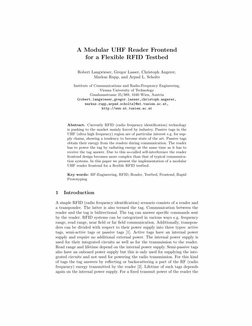
Figure 1 depicts the basic structure of the RFID testbed. The main reconfig-urable components are a fixed-point DSP from Texas Instruments (TMS320C6416)and a Xilinx Virtex II FPGA. Additionally, the testbed contains two digital toanalog converters (16 bits) and two analog to digital converters (14 bits). AnEthernet interface connects the DSP to a PC thus allowing for communicating
A Modular UHF Reader Frontend for a Flexible RFID Testbed 3
with an external application running on a PC. The testbed hardware, consist-
Rapid prototyping board
TI DSP
(TMS320C6416)
Protocol Stack
Xilinx Virtex II FPGA
Signal
Processing
DAC
RF
Front End
ADC
Eth
ern
et
In
terf
ace
Fig. 1. Block diagram of the RFID testbed
ing of a rapid prototyping board [4] and an analog frontend, is selected to beindependent from a specific standard or implementation. Hence, both the pro-tocol stack and the signal processing parts are mapped to the DSP and FPGAavailable at the board, respectively. Also the RF frontend is flexible in termsof various parameters applicable in RFID systems, e.g. modulation schemes,different timings and signal bandwidths.
Data
Encoding
MUX
1
TX
FilterASK
TX Control
Symbol
DecoderRX
Filter
Sync
RX
Ctrl
digital stream input
DSP
Protocol
State
Machine
Reg, IR
TX
RX
digital stream output
to D
AC
fro
m A
DC
X
13.56
MHz
FPGA
X
X
90°
Fig. 2. FPGA architecture of the RFID testbed
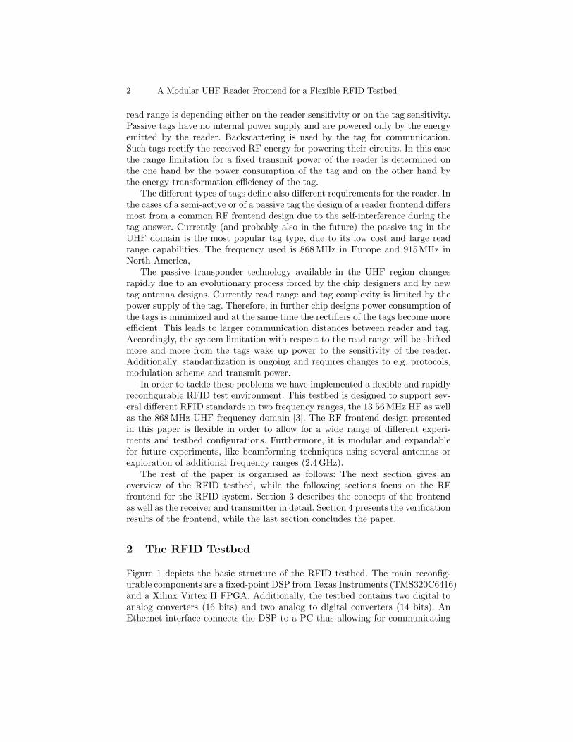
A generic architecture that supports the EPC global standard in the HF [5]and UHF domain [6] as well as the ISO15693 [7] standard is shown in Figure 2.The transmitter is composed of the DSP to FPGA interface, a symbol encoder,a transmit state machine, the multiplexer to switch to continuous carrier mode,a modulator, upconverter to 13.56 MHz and finally the transmit filter. In case ofan implementation in the UHF frequency domain the output signal is further up-and downconverted to 868 MHz in the RF frontend. The signal sampled at thereceiver is also centered at 13.56 MHz in the ADC. Thereafter, it is first bandpassfiltered to reduce the noise bandwidth, downconverted using an IQ demodulator,integrated and, finally the bits are detected using an algorithm that adapts its
4 A Modular UHF Reader Frontend for a Flexible RFID Testbed
threshold according to the channel conditions [8]. Finally the decided levels aresynchronised, the symbols decoded and forwarded to the DSP.
Different test scenarios on various levels, e.g. on the protocol stack and thesignal processing algorithms, are carried out. This includes for example anticolli-sion scenarios [9] and complex application scenarios like the inventory of all tagsin the read range, as well as tracking the effects of different receiver architectures,with different demodulators or signal detection schemes for instance.
3 UHF Frontend
3.1 Frontend Concept
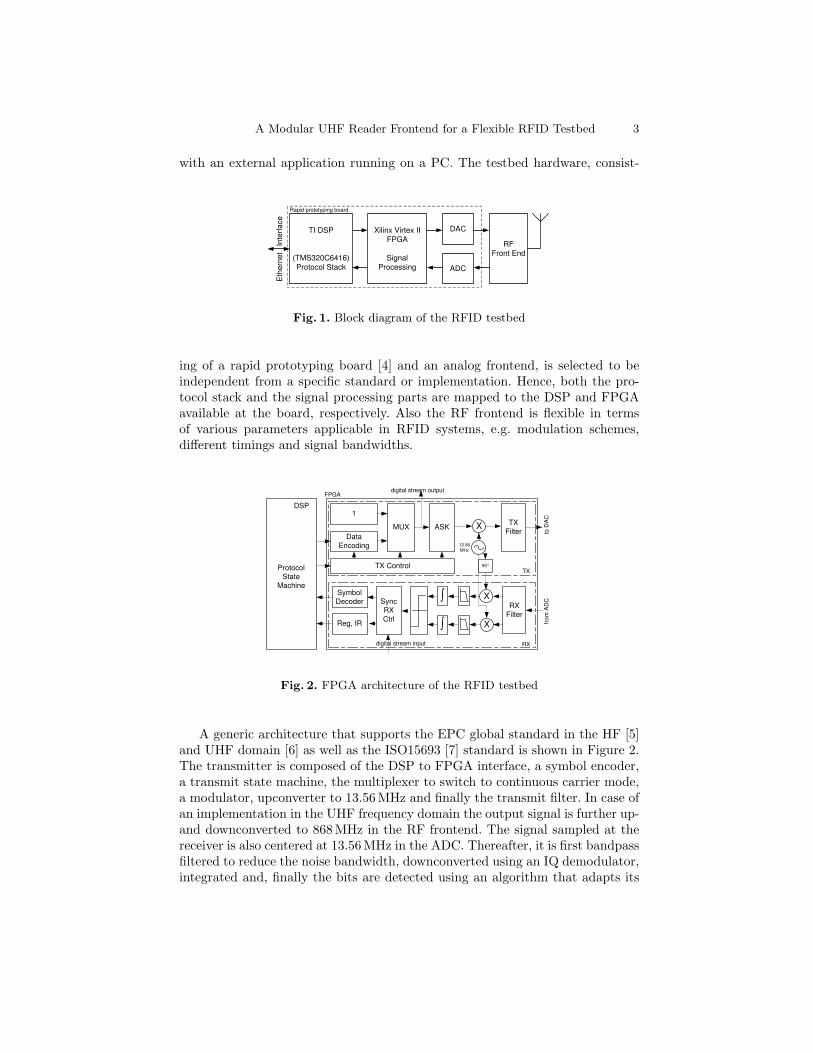
The concept and design for the transmitter and the receiver of the UHF fron-tend is flexible and only uses components off-the-shelf. In difference to a commonwireless communication frontend an additional module, the CCU (carrier com-pensation unit), was added for canceling the self-interference or direct couplingat the receiver [10]. A microcontroller unit is part of the system concept formonitoring and control purposes as well as for possible communication with therapid prototyping board for further applications. For operation in rather staticscenarios the microcontroller is not required. In Figure 3 the frontend conceptis illustrated.
Rx OUT
Tx IN
LO1 LO2
Tx OUT
Rx IN
Receiver
Transmitter
CCU
13.56 MHz
13.56 MHz
865 MHz - 868 MHz
865 MHz - 868 MHz
Mic
ro-
contr
oller
140 MHz
140 MHz
Fig. 3. Simplified block diagram of the UHF transmitter
Both transmitter and receiver are based on a low intermediate frequency (IF)to RF concept combined with a two stage frequency conversion [11]. Therefore,two local oscillator signals are required, which are provided by standard lab-oratory signal generators. The UHF frontend can be directly interlinked withthe DSP/FPGA board at a frequency of 13.56 MHz. The analog frontend is notlimited to the modulation schemes presently standardized for RFID due to the
A Modular UHF Reader Frontend for a Flexible RFID Testbed 5
fact that modulation and demodulation as well as pulse shaping are performedby the DSP/FPGA board. The frontend performs as a linear transponder andcan be used in a bi-static antenna scenario as well as in a mono-static antennascenario. In a bi-static antenna scenario transmitter and receiver each have aseparate antenna. For the mono-static scenario one common antenna is sharedby the transmitter and the receiver. When the frontend is configured for a singleantenna RFID reader scenario a circulator is required to provide decoupling be-tween transmitter and receiver. For further improvement of transmitter-receiverisolation active carrier compensation is implemented.
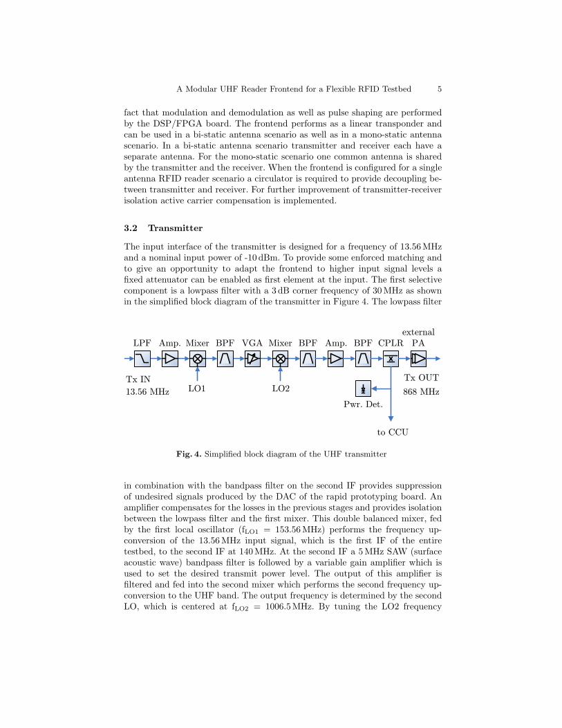
3.2 Transmitter
The input interface of the transmitter is designed for a frequency of 13.56 MHzand a nominal input power of -10 dBm. To provide some enforced matching andto give an opportunity to adapt the frontend to higher input signal levels afixed attenuator can be enabled as first element at the input. The first selectivecomponent is a lowpass filter with a 3 dB corner frequency of 30 MHz as shownin the simplified block diagram of the transmitter in Figure 4. The lowpass filter
13.56 MHz LO1
LPF BPFAmp. Mixer VGA BPFMixer Amp.
LO2Tx OUT
BPF CPLRexternal
PA
Tx IN
Pwr. Det.
to CCU
868 MHz
Fig. 4. Simplified block diagram of the UHF transmitter
in combination with the bandpass filter on the second IF provides suppressionof undesired signals produced by the DAC of the rapid prototyping board. Anamplifier compensates for the losses in the previous stages and provides isolationbetween the lowpass filter and the first mixer. This double balanced mixer, fedby the first local oscillator (fLO1 = 153.56MHz) performs the frequency up-conversion of the 13.56 MHz input signal, which is the first IF of the entiretestbed, to the second IF at 140 MHz. At the second IF a 5 MHz SAW (surfaceacoustic wave) bandpass filter is followed by a variable gain amplifier which isused to set the desired transmit power level. The output of this amplifier isfiltered and fed into the second mixer which performs the second frequency up-conversion to the UHF band. The output frequency is determined by the secondLO, which is centered at fLO2 = 1006.5MHz. By tuning the LO2 frequency
6 A Modular UHF Reader Frontend for a Flexible RFID Testbed
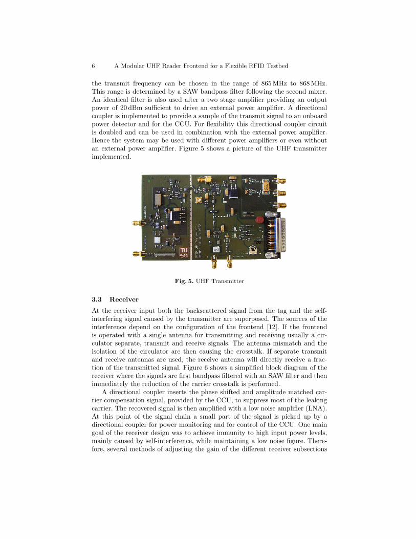
the transmit frequency can be chosen in the range of 865 MHz to 868 MHz.This range is determined by a SAW bandpass filter following the second mixer.An identical filter is also used after a two stage amplifier providing an outputpower of 20 dBm sufficient to drive an external power amplifier. A directionalcoupler is implemented to provide a sample of the transmit signal to an onboardpower detector and for the CCU. For flexibility this directional coupler circuitis doubled and can be used in combination with the external power amplifier.Hence the system may be used with different power amplifiers or even withoutan external power amplifier. Figure 5 shows a picture of the UHF transmitterimplemented.
Fig. 5. UHF Transmitter
3.3 Receiver
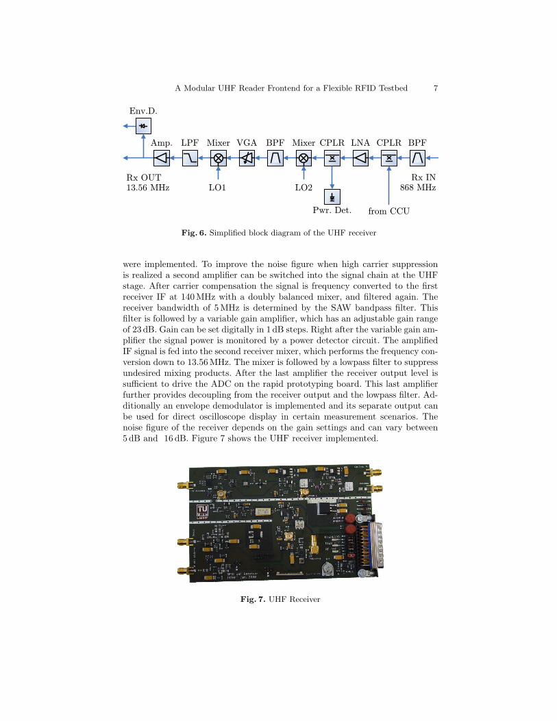
At the receiver input both the backscattered signal from the tag and the self-interfering signal caused by the transmitter are superposed. The sources of theinterference depend on the configuration of the frontend [12]. If the frontendis operated with a single antenna for transmitting and receiving usually a cir-culator separate, transmit and receive signals. The antenna mismatch and theisolation of the circulator are then causing the crosstalk. If separate transmitand receive antennas are used, the receive antenna will directly receive a frac-tion of the transmitted signal. Figure 6 shows a simplified block diagram of thereceiver where the signals are first bandpass filtered with an SAW filter and thenimmediately the reduction of the carrier crosstalk is performed.
A directional coupler inserts the phase shifted and amplitude matched car-rier compensation signal, provided by the CCU, to suppress most of the leakingcarrier. The recovered signal is then amplified with a low noise amplifier (LNA).At this point of the signal chain a small part of the signal is picked up by adirectional coupler for power monitoring and for control of the CCU. One maingoal of the receiver design was to achieve immunity to high input power levels,mainly caused by self-interference, while maintaining a low noise figure. There-fore, several methods of adjusting the gain of the different receiver subsections
A Modular UHF Reader Frontend for a Flexible RFID Testbed 7
Mixer
LO2LO1
BPFCPLRLNALPF BPF
13.56 MHz
Pwr. Det.
VGAAmp.
Rx OUT
Env.D.
CPLRMixer
from CCU
868 MHzRx IN
Fig. 6. Simplified block diagram of the UHF receiver
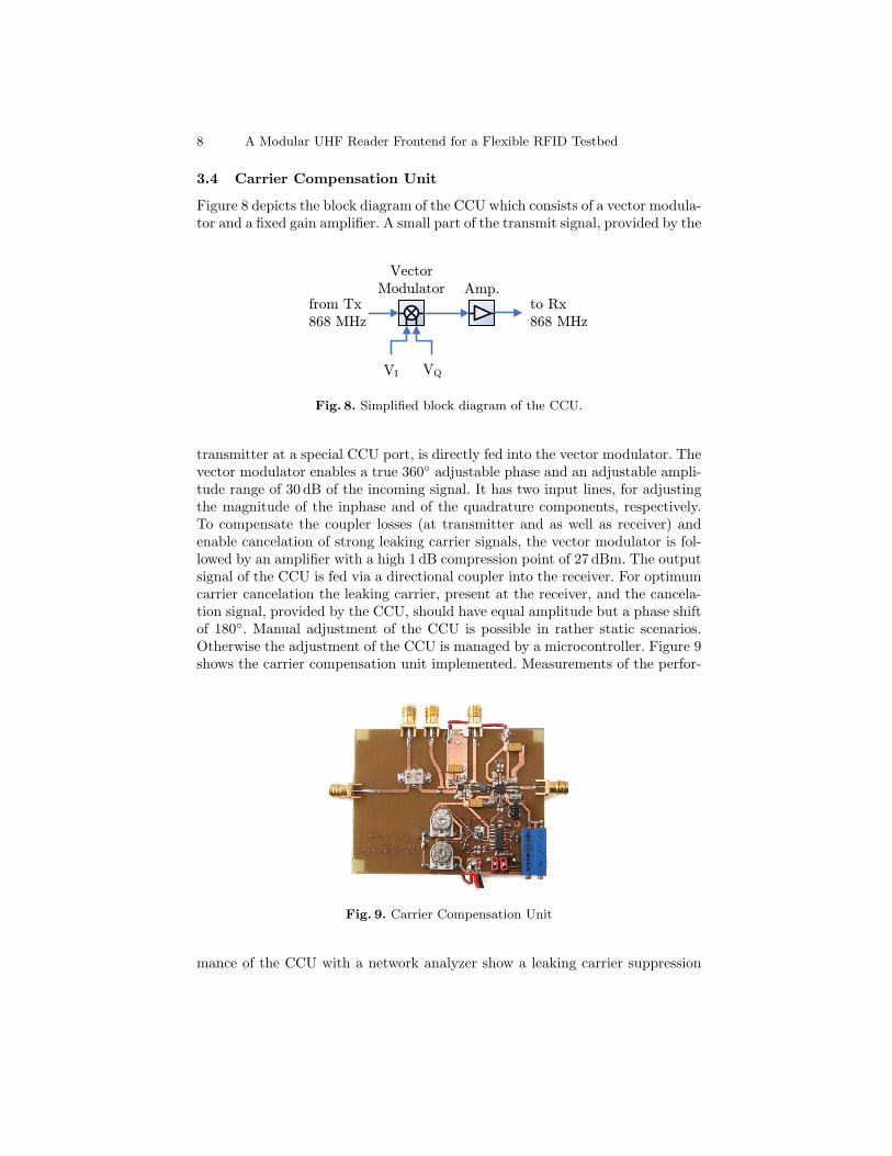
were implemented. To improve the noise figure when high carrier suppressionis realized a second amplifier can be switched into the signal chain at the UHFstage. After carrier compensation the signal is frequency converted to the firstreceiver IF at 140 MHz with a doubly balanced mixer, and filtered again. Thereceiver bandwidth of 5 MHz is determined by the SAW bandpass filter. Thisfilter is followed by a variable gain amplifier, which has an adjustable gain rangeof 23 dB. Gain can be set digitally in 1 dB steps. Right after the variable gain am-plifier the signal power is monitored by a power detector circuit. The amplifiedIF signal is fed into the second receiver mixer, which performs the frequency con-version down to 13.56 MHz. The mixer is followed by a lowpass filter to suppressundesired mixing products. After the last amplifier the receiver output level issufficient to drive the ADC on the rapid prototyping board. This last amplifierfurther provides decoupling from the receiver output and the lowpass filter. Ad-ditionally an envelope demodulator is implemented and its separate output canbe used for direct oscilloscope display in certain measurement scenarios. Thenoise figure of the receiver depends on the gain settings and can vary between5 dB and 16 dB. Figure 7 shows the UHF receiver implemented.
Fig. 7. UHF Receiver
8 A Modular UHF Reader Frontend for a Flexible RFID Testbed
3.4 Carrier Compensation Unit
Figure 8 depicts the block diagram of the CCU which consists of a vector modula-tor and a fixed gain amplifier. A small part of the transmit signal, provided by the
VectorModulator Amp.
from Tx868 MHz
to Rx868 MHz
VI VQ
Fig. 8. Simplified block diagram of the CCU.
transmitter at a special CCU port, is directly fed into the vector modulator. Thevector modulator enables a true 360◦ adjustable phase and an adjustable ampli-tude range of 30 dB of the incoming signal. It has two input lines, for adjustingthe magnitude of the inphase and of the quadrature components, respectively.To compensate the coupler losses (at transmitter and as well as receiver) andenable cancelation of strong leaking carrier signals, the vector modulator is fol-lowed by an amplifier with a high 1 dB compression point of 27 dBm. The outputsignal of the CCU is fed via a directional coupler into the receiver. For optimumcarrier cancelation the leaking carrier, present at the receiver, and the cancela-tion signal, provided by the CCU, should have equal amplitude but a phase shiftof 180◦. Manual adjustment of the CCU is possible in rather static scenarios.Otherwise the adjustment of the CCU is managed by a microcontroller. Figure 9shows the carrier compensation unit implemented. Measurements of the perfor-
Fig. 9. Carrier Compensation Unit
mance of the CCU with a network analyzer show a leaking carrier suppression
A Modular UHF Reader Frontend for a Flexible RFID Testbed 9
of up to 65 dB. This ultimate value was measured in a wired scenario and willnot be fully achieved in real open scenarios with moving scatterers.
4 Verification Measurement
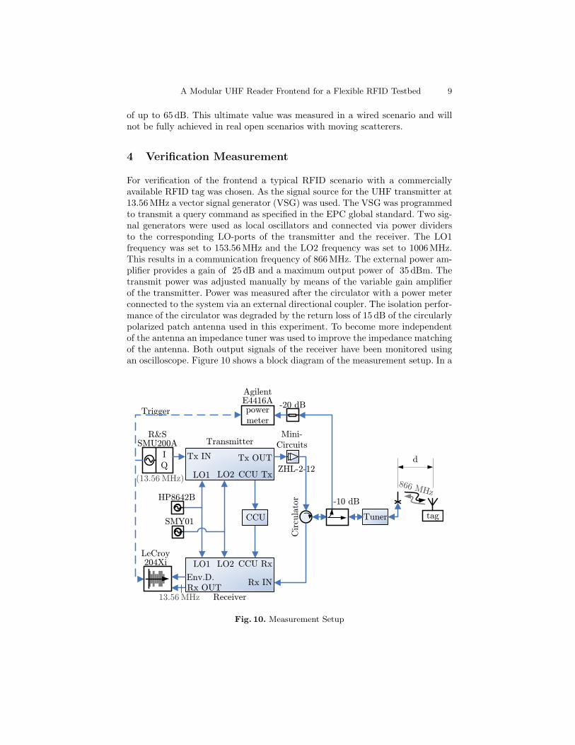
For verification of the frontend a typical RFID scenario with a commerciallyavailable RFID tag was chosen. As the signal source for the UHF transmitter at13.56 MHz a vector signal generator (VSG) was used. The VSG was programmedto transmit a query command as specified in the EPC global standard. Two sig-nal generators were used as local oscillators and connected via power dividersto the corresponding LO-ports of the transmitter and the receiver. The LO1frequency was set to 153.56 MHz and the LO2 frequency was set to 1006 MHz.This results in a communication frequency of 866 MHz. The external power am-plifier provides a gain of 25 dB and a maximum output power of 35 dBm. Thetransmit power was adjusted manually by means of the variable gain amplifierof the transmitter. Power was measured after the circulator with a power meterconnected to the system via an external directional coupler. The isolation perfor-mance of the circulator was degraded by the return loss of 15 dB of the circularlypolarized patch antenna used in this experiment. To become more independentof the antenna an impedance tuner was used to improve the impedance matchingof the antenna. Both output signals of the receiver have been monitored usingan oscilloscope. Figure 10 shows a block diagram of the measurement setup. In a
Tuner
Rx OUT
R&S SMU200A
IQ
tag
Tx IN
SMY01
HP8642B
LO1
LO1
LO2
LO2
CCU Tx
CCU Rx
Tx OUT
Rx IN
Mini-Circuits
Cir
cula
tor
ZHL-2-12
powermeter
Agilent E4416A
Trigger
-10 dB
d
-20 dB
Receiver
Transmitter
LeCroy 204Xi
Env.D.
CCU
866 MHz
(13.56 MHz)
13.56 MHz
Fig. 10. Measurement Setup
10 A Modular UHF Reader Frontend for a Flexible RFID Testbed
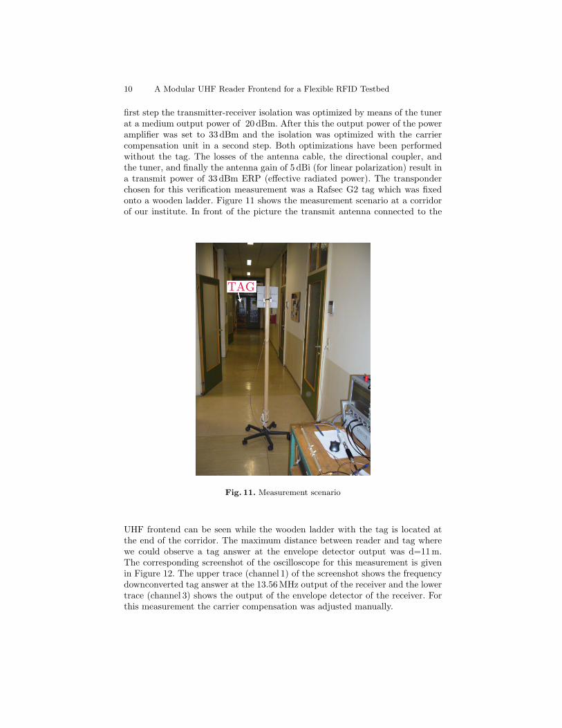
first step the transmitter-receiver isolation was optimized by means of the tunerat a medium output power of 20 dBm. After this the output power of the poweramplifier was set to 33 dBm and the isolation was optimized with the carriercompensation unit in a second step. Both optimizations have been performedwithout the tag. The losses of the antenna cable, the directional coupler, andthe tuner, and finally the antenna gain of 5 dBi (for linear polarization) result ina transmit power of 33 dBm ERP (effective radiated power). The transponderchosen for this verification measurement was a Rafsec G2 tag which was fixedonto a wooden ladder. Figure 11 shows the measurement scenario at a corridorof our institute. In front of the picture the transmit antenna connected to the
Fig. 11. Measurement scenario
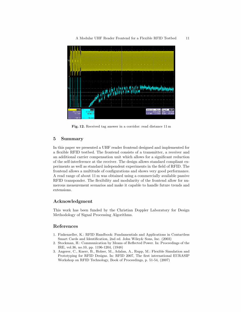
UHF frontend can be seen while the wooden ladder with the tag is located atthe end of the corridor. The maximum distance between reader and tag wherewe could observe a tag answer at the envelope detector output was d=11 m.The corresponding screenshot of the oscilloscope for this measurement is givenin Figure 12. The upper trace (channel 1) of the screenshot shows the frequencydownconverted tag answer at the 13.56 MHz output of the receiver and the lowertrace (channel 3) shows the output of the envelope detector of the receiver. Forthis measurement the carrier compensation was adjusted manually.
A Modular UHF Reader Frontend for a Flexible RFID Testbed 11
Fig. 12. Received tag answer in a corridor: read distance 11 m
5 Summary
In this paper we presented a UHF reader frontend designed and implemented fora flexible RFID testbed. The frontend consists of a transmitter, a receiver andan additional carrier compensation unit which allows for a significant reductionof the self-interference at the receiver. The design allows standard compliant ex-periments as well as standard independent experiments in the field of RFID. Thefrontend allows a multitude of configurations and shows very good performance.A read range of about 11 m was obtained using a commercially available passiveRFID transponder. The flexibility and modularity of the frontend allow for nu-merous measurement scenarios and make it capable to handle future trends andextensions.
Acknowledgment
This work has been funded by the Christian Doppler Laboratory for DesignMethodology of Signal Processing Algorithms.
References
1. Finkenzeller, K.: RFID Handbook: Fundamentials and Applications in ContactlessSmart Cards and Identification, 2nd ed. John Wiley& Sons, Inc. (2003)
2. Stockman, H.: Communication by Means of Reflected Power. In: Proceedings of theIRE, vol.36, no.10, pp. 1196-1204, (1948)
3. Angerer, C., Knerr, B., Holzer, M., Adalan, A., Rupp, M.: Flexible Simulation andPrototyping for RFID Designs. In: RFID 2007, The first international EURASIPWorkshop on RFID Technology, Book of Proceedings, p. 51-54, (2007)
12 A Modular UHF Reader Frontend for a Flexible RFID Testbed
4. Meindl-Pfeiffer, G., Kloibhofer, R., Kaltenberger, F., Humer, G.: Multi-StandardDevelopment and Measuring Platform for MIMO-Software Defined Radio. In: Pro-ceedings of the EUSIPCO, Antalya, Turkey, Sept. 2005, invited.
5. EPCGlobal: EPC Global HF Version 2, document Version 0.3. January 2007.6. EPCGlobal: EPC Radio-Frequency Identity Prototcols Class-1 Generation-2 UHF
RFID Protocol for Communications at 860MH - 960 MHz, Version 1.2.0 (2007)7. ISO / IEC: ISO / IEC 15693, Identification Cards - Contactless Integrated Circuit
Cards - Vicinity Cards. January 2000.8. Angerer, C.: A Digital Receiver Architecture for RFID Readers. In: SIES 2008, Third
International Symposium on Industrial Embedded Systems. Montpellier, France,2008.
9. Knerr, B., Holzer, M., Angerer, C., Rupp, M.: Slot-by-slot maximum likelihood es-timation of tag populations in framed slotted aloha protocols. In: Proceedings ofInternational Symposium on Performance Evaluation of Computer and Telecommu-nication Systems (SPECTS), Edinburgh, UK, 2008.
10. Curty, J.P., Declercq, M., Dehollain, C., Joehl, N.: Design and Optimization ofPassive UHF RFID Systems. Springer Science+Business Media, LLC (2007)
11. Langwieser, R., Fischer, M., Scholtz, A.L., Rupp, M., Humer, G.: Rapid Prototyp-ing for RF-Transmitters and Receivers. In: Communication Systems and Networks2006., ACTA Press (2006)
12. Penttila, K., Sydanheimo, L. and Kivikoski, M.: Implementation of Tx/Rx isola-tion in an RFID reader. In: Int. J. Radio Frequency Identification Technology andApplications, vol. 1, No. 1, pp.7489. (2006)
Related Documents