2184 IEEE TRANSACTIONS ON ANTENNAS AND PROPAGATION, VOL. 58, NO. 7, JULY 2010 A Modified Bow-Tie Antenna for Improved Pulse Radiation Andrian Andaya Lestari, Member, IEEE, Endon Bharata, Andriyan Bayu Suksmono, Senior Member, IEEE, Adit Kurniawan, Alexander G. Yarovoy, Senior Member, IEEE, and Leo P. Ligthart, Fellow, IEEE Abstract—The analysis, design, and realization of a modified bow-tie antenna optimized for impulse ground penetrating radar (GPR) applications is described. The proposed antenna shows improved properties important for GPR, which include its compact size (in comparison with a conventional bow-tie antenna) and ability to radiate UWB pulses with increased amplitude and very small late-time ringing. A substantial increase in the amplitude of the transmitted pulse is achieved by utilizing radiation from discontinuities introduced by the resistive loading employed in the antenna to suppress late-time ringing. By choosing an optimal distance between the antenna’s feed point and the location of the resistive loading, radiations that occur from the antenna’s feed point and the mentioned discontinuities at the resistive loading will combine constructively in the boreside direction of the antenna. As a result, one will observe a substantial increase of the amplitude of the transmitted pulse in the boreside direction. Furthermore, an analytical expression describing approximate time-harmonic cur- rent distribution is derived to indicate an optimal resistive loading profile for the proposed antenna. Additionally, the traveling-wave current distribution of the antenna is theoretically analyzed to examine the applicability of the obtained time-harmonic expression for pulse excitation. It has been found that when the antenna is resis- tively loaded both the time-harmonic and traveling-wave currents decay to approach nearly the same value at the end section of the antenna. As the amount of current at the antenna ends corresponds to the level of reflection which occurs there, the derived expression is found to be useful to indicate an optimal loading profile for the proposed antenna. A theoretical model of the proposed antenna has been developed to perform numerical analysis using a modified NEC-2 code. In addition, an experimental verification has been carried out and both the simulation and experiment confirmed the improved properties of the proposed antenna. Index Terms—Bow-tie antenna, ground penetrating radar (GPR), resistive loading, ultrawideband (UWB) antenna. I. INTRODUCTION T HE wideband nature of bow-tie antennas has always been very attractive for implementation in a wide range of ap- plications. The wideband characteristic of bow-tie antennas was Manuscript received April 12, 2009; revised December 21, 2009; accepted January 25, 2010. Date of publicationApril 22, 2010; date of current version July 08, 2010. This work was supported in part by the International Research Centre for Telecommunications and Radar (IRCTR)—Delft University of Technology, The Netherlands, and Radar & Communication Systems (RCS), Indonesia. A. A. Lestari is with the International Research Centre for Telecom and Radar (IRCTR), Bandung Institute of Technology, Bandung 40132, Indonesia, and also with IRCTR, Delft University of Technology, 2628 CD Delft, The Nether- lands (e-mail: [email protected]). E. Bharata, A. B. Suksmono, and A. Kurniawan are with the International Research Centre for Telecom and Radar (IRCTR), Bandung Institute of Tech- nology, Bandung 40132, Indonesia. A. G. Yarovoy and L. P. Ligthart are with the International Research Centre for Telecom and Radar (IRCTR), Delft University of Technology, 2628 CD Delft, The Netherlands. Digital Object Identifier 10.1109/TAP.2010.2048853 already reported in the past by many investigators including Brown and Woodward who carried out an experimental inves- tigation of bow-tie antennas [1], Carrel who was the first to show analytically that the bandwidth of a bow-tie antenna de- pends on the bow-tie flare angle [2], Lambert et al. [3] and Lee and Smith [4] who improved Carrel’s analytical solution, and Shlager et al. [5] and Leat et al. [6] who developed a numer- ical model for a bow-tie antenna. In the last couple of decades bow-tie antennas have been introduced in many ultrawideband (UWB) applications for which their bandwidth was enlarged by means of various loading schemes, which include resistive loading [5], reactive loading [7], and combination of those [8]. Ground penetrating radar (GPR) is one of the applications in which resistively-loaded bow-tie antennas are frequently used due to their relatively simple and practical geometry and their ability to transmit UWB transient pulses properly. The antenna proposed in this paper is aimed mainly at this application. For impulse GPR it is generally required that the antenna have sufficiently large bandwidth and a constant phase center. The former is needed to allow transmission of UWB transient pulses with suppressed late-time ringing to avoid masking of targets while the latter is needed to avoid widening of the pulse over time. Late-time ringing is caused by internal reflections in the antenna due to insufficient antenna bandwidth. With re- spect to this, resistive loading has always been the most pop- ular loading scheme for enlarging antenna bandwidth due to its simplicity. Several types of resistive load commonly applied on GPR antennas include resistive sheets [5], lumped resistors [9], and foam-based absorbers [8], which have been found ef- fective to enlarge antenna bandwidth for suppressing late-time ringing. However, substantial decrease of antenna efficiency is the price that has to be paid when using purely resistive loading. It has been indicated that in this case antenna radiation effi- ciency might drop to as low as 30% as a large portion of the energy supplied to the antenna is dissipated by the resistive load [10]. To minimize such a great loss in radiation efficiency, non-dissipative loading, i.e., reactive (capacitive or inductive) loading, has been introduced [11], [12]. Unfortunately such re- active loading, usually realized as gaps or slots in the antenna, if not combined with any form of resistive load would not be suitable for impulse GPR applications since it usually exhibits a significant level of late-time ringing which might seriously de- grade the GPR performance [10], [12]. Such late-time ringing is most likely the result of distributed discontinuities introduced by the gaps or the slots. In view of the abovementioned problem, in this paper we introduce a modified resistively-loaded bow-tie antenna which has been optimized for an impulse GPR applica- tion. The proposed antenna has been designed to enable trans- 0018-926X/$26.00 © 2010 IEEE

Welcome message from author
This document is posted to help you gain knowledge. Please leave a comment to let me know what you think about it! Share it to your friends and learn new things together.
Transcript
2184 IEEE TRANSACTIONS ON ANTENNAS AND PROPAGATION, VOL. 58, NO. 7, JULY 2010
A Modified Bow-Tie Antenna for Improved PulseRadiation
Andrian Andaya Lestari, Member, IEEE, Endon Bharata, Andriyan Bayu Suksmono, Senior Member, IEEE,Adit Kurniawan, Alexander G. Yarovoy, Senior Member, IEEE, and Leo P. Ligthart, Fellow, IEEE
Abstract—The analysis, design, and realization of a modifiedbow-tie antenna optimized for impulse ground penetrating radar(GPR) applications is described. The proposed antenna showsimproved properties important for GPR, which include its compactsize (in comparison with a conventional bow-tie antenna) andability to radiate UWB pulses with increased amplitude and verysmall late-time ringing. A substantial increase in the amplitudeof the transmitted pulse is achieved by utilizing radiation fromdiscontinuities introduced by the resistive loading employed inthe antenna to suppress late-time ringing. By choosing an optimaldistance between the antenna’s feed point and the location of theresistive loading, radiations that occur from the antenna’s feedpoint and the mentioned discontinuities at the resistive loading willcombine constructively in the boreside direction of the antenna. Asa result, one will observe a substantial increase of the amplitude ofthe transmitted pulse in the boreside direction. Furthermore, ananalytical expression describing approximate time-harmonic cur-rent distribution is derived to indicate an optimal resistive loadingprofile for the proposed antenna. Additionally, the traveling-wavecurrent distribution of the antenna is theoretically analyzed toexamine the applicability of the obtained time-harmonic expressionfor pulse excitation. It has been found that when the antenna is resis-tively loaded both the time-harmonic and traveling-wave currentsdecay to approach nearly the same value at the end section of theantenna. As the amount of current at the antenna ends correspondsto the level of reflection which occurs there, the derived expressionis found to be useful to indicate an optimal loading profile for theproposed antenna. A theoretical model of the proposed antennahas been developed to perform numerical analysis using a modifiedNEC-2 code. In addition, an experimental verification has beencarried out and both the simulation and experiment confirmed theimproved properties of the proposed antenna.
Index Terms—Bow-tie antenna, ground penetrating radar(GPR), resistive loading, ultrawideband (UWB) antenna.
I. INTRODUCTION
T HE wideband nature of bow-tie antennas has always beenvery attractive for implementation in a wide range of ap-
plications. The wideband characteristic of bow-tie antennas was
Manuscript received April 12, 2009; revised December 21, 2009; acceptedJanuary 25, 2010. Date of publicationApril 22, 2010; date of current version July08, 2010. This work was supported in part by the International Research Centrefor Telecommunications and Radar (IRCTR)—Delft University of Technology,The Netherlands, and Radar & Communication Systems (RCS), Indonesia.
A. A. Lestari is with the International Research Centre for Telecom and Radar(IRCTR), Bandung Institute of Technology, Bandung 40132, Indonesia, andalso with IRCTR, Delft University of Technology, 2628 CD Delft, The Nether-lands (e-mail: [email protected]).
E. Bharata, A. B. Suksmono, and A. Kurniawan are with the InternationalResearch Centre for Telecom and Radar (IRCTR), Bandung Institute of Tech-nology, Bandung 40132, Indonesia.
A. G. Yarovoy and L. P. Ligthart are with the International Research Centrefor Telecom and Radar (IRCTR), Delft University of Technology, 2628 CDDelft, The Netherlands.
Digital Object Identifier 10.1109/TAP.2010.2048853
already reported in the past by many investigators includingBrown and Woodward who carried out an experimental inves-tigation of bow-tie antennas [1], Carrel who was the first toshow analytically that the bandwidth of a bow-tie antenna de-pends on the bow-tie flare angle [2], Lambert et al. [3] and Leeand Smith [4] who improved Carrel’s analytical solution, andShlager et al. [5] and Leat et al. [6] who developed a numer-ical model for a bow-tie antenna. In the last couple of decadesbow-tie antennas have been introduced in many ultrawideband(UWB) applications for which their bandwidth was enlargedby means of various loading schemes, which include resistiveloading [5], reactive loading [7], and combination of those [8].Ground penetrating radar (GPR) is one of the applications inwhich resistively-loaded bow-tie antennas are frequently useddue to their relatively simple and practical geometry and theirability to transmit UWB transient pulses properly. The antennaproposed in this paper is aimed mainly at this application.
For impulse GPR it is generally required that the antennahave sufficiently large bandwidth and a constant phase center.The former is needed to allow transmission of UWB transientpulses with suppressed late-time ringing to avoid masking oftargets while the latter is needed to avoid widening of the pulseover time. Late-time ringing is caused by internal reflectionsin the antenna due to insufficient antenna bandwidth. With re-spect to this, resistive loading has always been the most pop-ular loading scheme for enlarging antenna bandwidth due toits simplicity. Several types of resistive load commonly appliedon GPR antennas include resistive sheets [5], lumped resistors[9], and foam-based absorbers [8], which have been found ef-fective to enlarge antenna bandwidth for suppressing late-timeringing. However, substantial decrease of antenna efficiency isthe price that has to be paid when using purely resistive loading.It has been indicated that in this case antenna radiation effi-ciency might drop to as low as 30% as a large portion of theenergy supplied to the antenna is dissipated by the resistiveload [10]. To minimize such a great loss in radiation efficiency,non-dissipative loading, i.e., reactive (capacitive or inductive)loading, has been introduced [11], [12]. Unfortunately such re-active loading, usually realized as gaps or slots in the antenna,if not combined with any form of resistive load would not besuitable for impulse GPR applications since it usually exhibits asignificant level of late-time ringing which might seriously de-grade the GPR performance [10], [12]. Such late-time ringingis most likely the result of distributed discontinuities introducedby the gaps or the slots. In view of the abovementioned problem,in this paper we introduce a modified resistively-loaded bow-tieantenna which has been optimized for an impulse GPR applica-tion. The proposed antenna has been designed to enable trans-
0018-926X/$26.00 © 2010 IEEE
LESTARI et al.: A MODIFIED BOW-TIE ANTENNA FOR IMPROVED PULSE RADIATION 2185
mission of UWB pulses with higher radiation efficiency andlower level of late-time ringing in comparison with other re-sistively-loaded planar antennas of a comparable or even largersize. This has been achieved by using the principle introducedin [8] in which secondary radiation originating from disconti-nuities in the antenna is utilized to increase the amplitude of theradiated pulse.
Furthermore, in this paper an analytical expression describingapproximate time-harmonic current distribution is derived to in-dicate an optimal resistive loading profile for the proposed an-tenna. Additionally, the traveling-wave current distribution ofthe antenna is theoretically analyzed to examine the validity ofthe obtained time-harmonic expression.
This paper is organized as follows. In Section II we describethe design of the proposed antenna. In Section III we derivethe analytical expression for approximate time-harmonic cur-rent distribution of the proposed antenna. In Section IV we de-scribe the numerical model to evaluate the antenna design withthe selected loading profile. Finally, an experimental verifica-tion of the antenna design is reported in Section V. This paperis closed with the conclusions presented in Section VI.
II. ANTENNA DESIGN
The main objectives of the antenna design reported in thispaper are as follows.
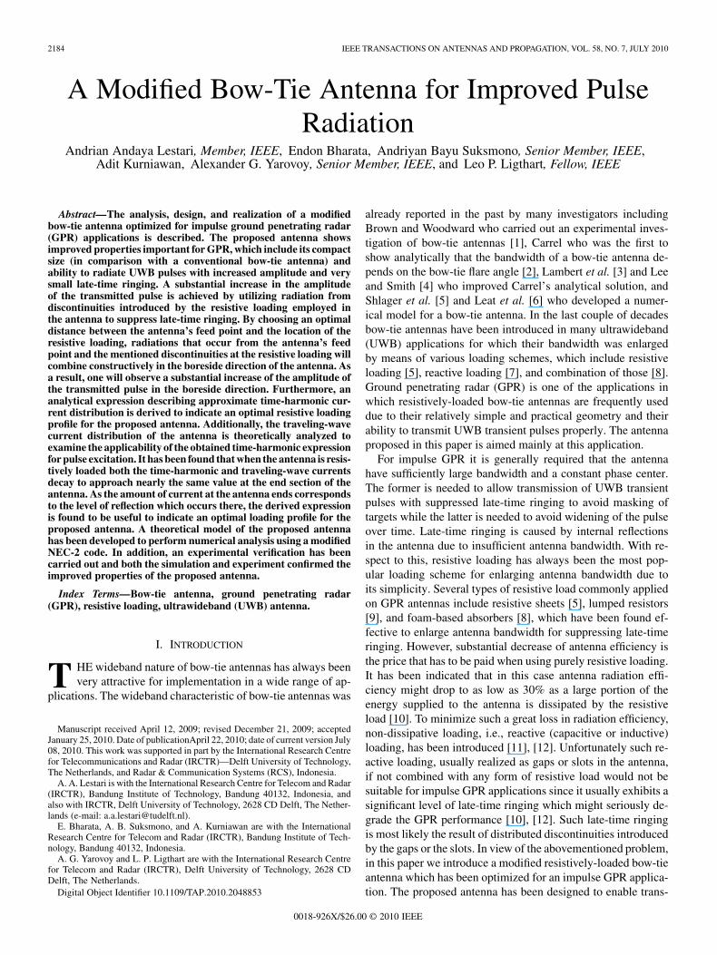
• We wish to design a UWB antenna for transmission ofshort monocycle pulses with duration of 0.8 ns (centralfrequency of app. 1 GHz) for a high-resolution GPR. Thewaveform and spectrum of the pulse measured directlyfrom the GPR system employed in this work are plottedin Fig. 1.
• The antenna should have relatively high radiation effi-ciency and suppressed late-time ringing to improve theGPR performance.
• The design should be adequately simple, practical andcompact for implementation of the antenna in a commer-cially-available GPR system.
In this work the proposed design is based on a bow-tie antenna.Resistively-loaded planar (dipole) antennas including bow-tieantennas are very attractive and widely used for commercialGPR systems as their planar geometry allows simple imple-mentation in the GPR and ease of operation. Furthermore, theantenna’s casing can be designed to become a shield (to mini-mize TX-RX antenna coupling and interference) and a reflector(to maximize radiation into the subsurface), and as a result oneobtains a practical and cost-effective directive antenna satisfac-tory for most of commercial GPR systems. Improved directiveUWB antennas such as dielectric-filled TEM horn, Vivaldi, andtapered slot antennas are usually less attractive for commercialGPR systems as they tend to be more expensive, more com-plex in implementation and bulky in shape, especially whenshielding is required.
Traditionally, GPR makes use of bow-tie antennas loadedwith resistive coating, which, as mentioned above, is handi-capped with a substantial drop of radiation efficiency. To im-prove radiation efficiency when using resistive loading for pulseradiation, in this work we apply the method introduced in [8].By this method, two main sources of radiation are created in
Fig. 1. Monocycle with 0.8 ns duration employed as the exciting pulse:(a) waveform, (b) spectrum.
the antenna, i.e., the main source located at the antenna’s feedpoint and the secondary source at an artificial discontinuity inthe antenna. In this work the antenna is designed to have a sec-ondary source of radiation at the discontinuity in the antenna in-troduced by the employed resistive loading. The radiation fromthe secondary source is then utilized to strengthen pulse radi-ation in the boreside direction, which can be achieved whenthe distance from the main source (i.e., the feed point) to thesecondary source (i.e., the discontinuity caused by the resistiveloading) is chosen to be [8]
(1)
where is the speed of light, is the central frequency of theexciting pulse, and is the effective relative permittivity ofthe employed substrate (in case of a printed antenna). When(1) is satisfied, radiation from the discontinuity will combineconstructively with radiation form the feed point, resulting ina maximum increase in the amplitude of the pulse transmittedin the boreside direction of the antenna. A discontinuity in theantenna can occur as a result of abrupt changes in the antennageometry (e.g., bends, slots, gaps, etc.) or material (e.g., dielec-tric, substrate, loading, etc.). Here we attempt to maximize thesecondary radiation by designing an abrupt change in both theantenna geometry and material to occur at the same locations.
2186 IEEE TRANSACTIONS ON ANTENNAS AND PROPAGATION, VOL. 58, NO. 7, JULY 2010
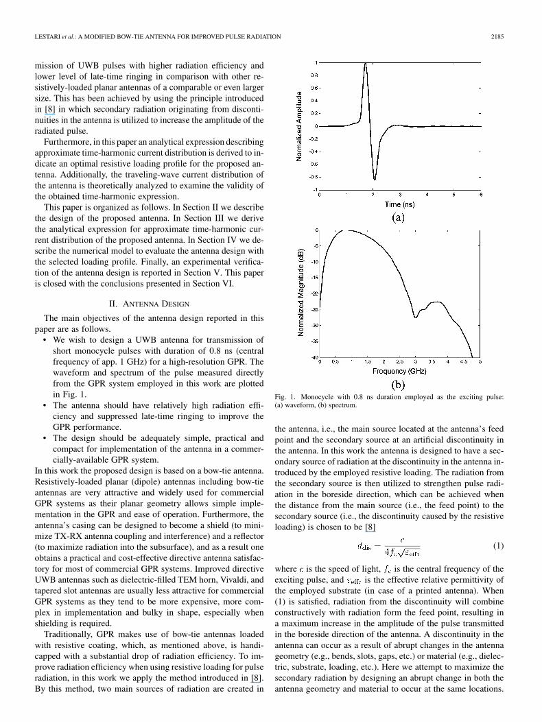
Fig. 2. Geometry of a wire bow-tie antenna with 25 cm wires on each arm and10 angular separation between the neighboring wires [13].
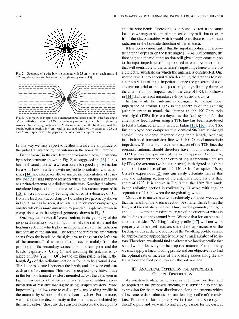
Fig. 3. Geometry of the proposed antenna for realization on FR4: the flare angleof the radiating section is 120 ; angular separation between the neighboringwires in the radiating section is 10 ; distance between the feed point and thebends/loading section is 4 cm; total length and width of the antenna is 23 cmand 7 cm, respectively. The gaps are the locations of chip resistors.
In this way we may expect to further increase the amplitude ofthe pulse transmitted by the antenna in the boreside direction.
Furthermore, in this work we approximate a bow-tie antennaby a wire structure shown in Fig. 2, as suggested in [13]. It hasbeen indicated that such a wire structure is a good approximationfor a solid bow-tie antenna with respect to its radiation character-istics [14] and moreover allows simple implementation of resis-tive loading using lumped resistors when the antenna is realizedas a printed antenna on a dielectric substrate. Keeping the above-mentioned aspects in mind, the wire bow-tie structure reported in[13] is here modified by bending the wires at a distance offrom the feed point according to (1), leading to a geometry shownin Fig. 3. As can be seen, it results in a much more compact ge-ometry which is more amenable to practical implementation incomparison with the original geometry shown in Fig. 2.
One may define two different sections in the geometry of theproposed antenna shown in Fig. 3, namely the radiating and theloading sections, which play an important role in the radiationmechanism of the antenna. The former occupies the area whichspans from the bends on the right arm to those on the left armof the antenna. In this part radiation occurs mainly from theprimary and the secondary sources, i.e., the feed point and thebends, respectively. Using (1) and assuming the antenna is re-alized on FR4 , for the exciting pulse in Fig. 1, thelength of the radiating section is found to be around 4 cm.The latter is located between the bends and the wire ends oneach arm of the antenna. This part is occupied by resistive loadsin the form of lumped resistors mounted across the gaps seen inFig. 3. It is obvious that such a wire structure simplifies imple-mentation of resistive loading by using lumped resistors. Moreimportantly, it allows one to easily apply any loading profile inthe antenna by selection of the resistor’s values. Furthermore,we notice that the discontinuity in the antenna is contributed bythe first resistors (those are the resistors nearest to the feed point)
and the wire bends. Therefore, as they are located at the samelocation we may expect maximum secondary radiation to occurfrom the discontinuities which would contribute to maximumradiation in the boreside direction of the antenna.
It has been demonstrated that the input impedance of a bow-tie antenna depends on the flare angle [1]–[4]. Accordingly, theflare angle in the radiating section will give a large contributionto the input impedance of the proposed antenna. Another factorthat will contribute to the antenna’s input impedance is the usea dielectric substrate on which the antenna is constructed. Oneshould take it into account when designing the antenna to havea certain value of input impedance since the presence of a di-electric material at the feed point might significantly decreasethe antenna’s input impedance. In the case of FR4, it is shownin [14] that the input impedance drops by around 50 .
In this work the antenna is designed to exhibit inputimpedance of around 100 in the spectrum of the excitingpulse in order to match the antenna to the 100-Ohm twinsemi-rigid (TSR) line employed as the feed system for theantenna. A feed system using a TSR line has been introducedto feed a balanced antenna without balun [15], [16]. The TSRline employed here comprises two identical 50-Ohm semi-rigidcoaxial lines soldered together along their length, resultingin a balanced transmission line with 100-Ohm characteristicimpedance. To obtain a match termination of the TSR line, theproposed antenna should therefore have input impedance of100 within the spectrum of the exciting pulse. Accountingfor the aforementioned 50 drop of input impedance causedby FR4, the antenna (without substrate) is designed to exhibitan input impedance of around 150 in free space. UsingCarrel’s expressions [2] one can easily calculate that in thiscase the radiating section of the antenna should have a flareangle of 120 . It is shown in Fig. 3 that the 120 flare anglein the radiating section is realized by 13 wires with angularseparation of 10 between the neighboring wires.
Moreover, to make the antenna relatively compact, we requirethat the length of the loading section be smaller than 2 times thelength of the radiating section. Thus, for the geometry in Fig. 3and cm the maximum length of the outermost wires inthe loading section is around 9 cm. We note that for such a smallantenna the ideal Wu-King loading profile [17] will not workproperly with lumped resistors since the sharp increase of theloading values at the end section of the Wu-King profile cannotbe approximated appropriately only by a small number of resis-tors. Therefore, we should find an alternative loading profile thatwould work effectively for the proposed antenna. For simplicitywe shall apply a linear loading profile and our objective is to findthe optimal rate of increase of the loading values along the an-tenna from the feed point towards the antenna end.
III. ANALYTICAL EXPRESSION FOR APPROXIMATE
CURRENT DISTRIBUTION
As resistive loading using a series of lumped resistors willbe applied in the proposed antenna, it is advisable to find anexpression for the current distribution along the antenna whichallows one to determine the optimal loading profile of the resis-tors. To this end, for simplicity we first assume a wire (cylin-drical) dipole and we wish to find an expression for the current
LESTARI et al.: A MODIFIED BOW-TIE ANTENNA FOR IMPROVED PULSE RADIATION 2187
distribution along the dipole. As mentioned above, here we con-sider a loading profile in which the resistive loading increaseslinearly towards the antenna end. The loading will be applied tothe dipole, which is chosen to be aligned with the -axis withits feed point at the origin in Cartesian coordinates. The dipoleis assumed to be loaded along its length with lumped resistiveelements in series. The separation between adjacent elements isassumed to be sufficiently small in terms of wavelength. In thiscase the loading is expressed in impedance per unit length givenby
(2)
where is the rate of increase of the resistance (in Ohms/meter)and is the position along the antenna.
When a dipole with length and wire radius is fed atby a delta-function generator with EMF (electromotive force)
[Volts], assuming the positive time dependence the axialcomponent of the vector potential on the surface of theantenna satisfies the wave equation [17]
(3)
where is the wave number in the free space, is the totalaxial current in the antenna, is the Dirac delta function, andthe vector potential is given by
(4)
with
(5)
in which
(6)
where is the source coordinate and is the wire radius.It has been indicated in [17] that the ratio of vector potential
to current along the antenna is approximately con-stant and thus one may write
(7)
where is the expansion parameter at the maximum of currentand approximated by , which has
also been used for dipoles with purely capacitive loading in [11].Hence, (3) may be written as
(8)
where is the intrinsic impedance of the free space.Inserting (2) in (8) leads to
(9)
where
(10)
Except at the feed point the current must satisfy differ-ential equation
(11)
The solution to (11) can be written as
(12)
where and are the constants to be determined byboundary conditions, and Ai and Bi are the Airy functions.Imposing the boundary conditions at the wire end,we can express (12) as
(13)
where
(14)
(15)
Since (13) holds for a single wire dipole, the maximum valueof the resistor located at the end of the loading section can beapproximated by
(16)
where is the number of wires in the loading section.The selected loading profile determines the amount of cur-
rent at the end section of the antenna, which in turn determinesthe level of reflections occurring at the antenna end. For pulseexcitation, the time-domain response of the antenna generallyconsists of a main pulse transmitted directly from the feed pointand late-time ringing transmitted mainly from the antenna endas a result of the abovementioned reflections. The level of thelate-time ringing corresponds to the amount of current at theend section of the antenna due to the selected loading profile.Therefore, one can find an optimal loading profile which givesthe desired level of late-time ringing by adjusting the loadingprofile to give the same level of current at the end section of theantenna.
A level of late-time ringing of dB below the peak of themain pulse should be adequate for most of GPR applications[14]. Accordingly, we prescribe the level of current at the endsection of the antenna to be dB below its maximum valueat the feed point, for which a suitable loading profile is needed.For the proposed antenna (13) shows that when the last resistor
is chosen to be 10 k , it will result in a maximum level ofcurrent of dB at the end section of the antenna within the
dB level of the spectrum of the exciting 0.8 ns monocycle
2188 IEEE TRANSACTIONS ON ANTENNAS AND PROPAGATION, VOL. 58, NO. 7, JULY 2010
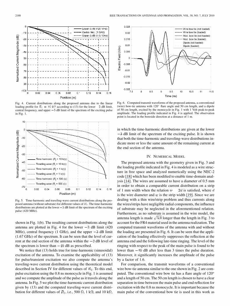
Fig. 4. Current distributions along the proposed antenna due to the linearloading profile for � � �� k� according to (13) for the lower �� dB limit,central frequency, and upper �� dB limit of the spectrum of the exciting pulsein Fig. 1.
Fig. 5. Time-harmonic and traveling-wave current distributions along the pro-posed antenna (without substrate) for different values of� . The time-harmonicdistributions are plotted at the lower�� dB limit of the spectrum of the excitingpulse (420 MHz).
shown in Fig. 1(b). The resulting current distributions along theantenna are plotted in Fig. 4 for the lower dB limit (420MHz), central frequency (1 GHz), and the upper dB limit(1.67 GHz) of the spectrum. It can be seen that the level of cur-rent at the end section of the antenna within the dB level ofthe spectrum is lower than dB as prescribed.
We notice that (13) holds true for time-harmonic (sinusoidal)excitation of the antenna. To examine the applicability of (13)for pulse/transient excitation we also compute the antenna’straveling-wave current distribution using the theoretical modeldescribed in Section IV for different values of . To this end,pulse excitation using the 0.8 ns monocycle in Fig. 1 is assumedand we compute the amplitude of the pulse as it travels along theantenna. In Fig. 5 we plot the time-harmonic current distributiongiven by (13) and the computed traveling-wave current distri-bution for different values of , i.e., 500 , 1 k , and 10 k ,
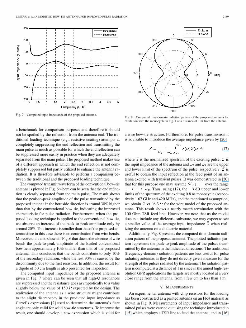
Fig. 6. Computed transmit waveforms of the proposed antenna, a conventional(wire) bow-tie antenna with 120 flare angle and 50 cm length, and a dipoleof 50 cm length, excited by the monocycle in Fig. 1 with 1 Volt peak-to-peakamplitude. The loading profile indicated in Fig. 4 is applied. The observationpoint is located in the boreside direction at a distance of 1 m.
in which the time-harmonic distributions are given at the lowerdB limit of the spectrum of the exciting pulse. It is shown
that both the time-harmonic and traveling-wave distributions in-dicate more or less the same amount of the remaining current atthe end section of the antenna.
IV. NUMERICAL MODEL
The proposed antenna with the geometry given in Fig. 3 andthe loading profile indicated in Fig. 4 is modeled as a wire struc-ture in free space and analyzed numerically using the NEC-2code [18] which has been modified to enable time-domain anal-ysis [14]. The wires are assumed to have a diameter of 0.5 mmin order to obtain a comparable current distribution on a stripof 1 mm width when the relation is satisfied, whereis the wire diameter and is the strip width [19]. Since we aredealing with a thin wire/strip problem and thus currents alongthe wires/strips have negligible radial components, the influenceof substrate may be neglected in the aforementioned relation.Furthermore, as no substrate is assumed in the wire model, theantenna length is made longer than the length in Fig. 3 toaccount for the FR4 material used in the antenna realization. Thecomputed transmit waveforms of the antenna with and withoutthe loading are presented in Fig. 6. It can be seen that the appli-cation of the loading effectively suppresses the reflection at theantenna end and the following late-time ringing. The level of theringing with respect to the peak of the main pulse is found to belower than dB after less than 3 times the pulse duration.Moreover, it significantly increases the amplitude of the pulseby a factor of 1.6.
For comparison, the transmit waveforms of a conventionalwire bow-tie antenna similar to the one shown in Fig. 2 are com-puted. The conventional wire bow tie has a flare angle of 120and a length of 50 cm. The 50 cm length is chosen to have a clearseparation in time between the main pulse and end reflection forexcitation with the 0.8 ns monocycle. It is important because themain pulse of the conventional bow tie is used in this work as
LESTARI et al.: A MODIFIED BOW-TIE ANTENNA FOR IMPROVED PULSE RADIATION 2189
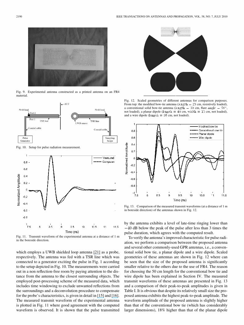
Fig. 7. Computed input impedance of the proposed antenna.
a benchmark for comparison purposes and therefore it shouldnot be spoiled by the reflection from the antenna end. The tra-ditional loading technique (e.g., resistive coating) attempts atcompletely suppressing the end reflection and transmitting themain pulse as much as possible for which the end reflection canbe suppressed more easily in practice when they are adequatelyseparated from the main pulse. The proposed method makes useof a different approach in which the end reflection is not com-pletely suppressed but partly utilized to enhance the antenna ra-diation. It is therefore advisable to perform a comparison be-tween the traditional and the proposed loading technique.
The computed transmit waveform of the conventional bow-tieantenna is plotted in Fig. 6 where can be seen that the end reflec-tion is clearly separated from the main pulse. The result showsthat the peak-to-peak amplitude of the pulse transmitted by theproposed antenna in the boreside direction is around 30% higherthan that by the conventional bow tie, indicating the improvedcharacteristic for pulse radiation. Furthermore, when the pro-posed loading technique is applied to the conventional bow tie,we observe an increase of the peak-to-peak amplitude only byaround 20%. This increase is smaller than that of the proposed an-tenna since in this case there is no contribution from wire bends.Moreover, it is also shown in Fig. 6 that due to the absence of wirebends the peak-to-peak amplitude of the loaded conventionalbow tie is approximately 10% smaller than that of the proposedantenna. This concludes that the bends contribute to only 10%of the secondary radiation, while the rest 90% is caused by thediscontinuity due to the first resistors. In addition, the result fora dipole of 50 cm length is also presented for inspection.
The computed input impedance of the proposed antenna isgiven in Fig. 7 where can be seen that all high-Q resonancesare suppressed and the resistance goes asymptotically to a valueslightly below the value of 150 expected by the design. Therealization of the antenna as a wire structure might contributeto the slight discrepancy in the predicted input impedance asCarrel’s expressions [2] used to determine the antenna’s flareangle are only valid for solid bow-tie structures. To improve theresult, one should develop a new expression which is valid for
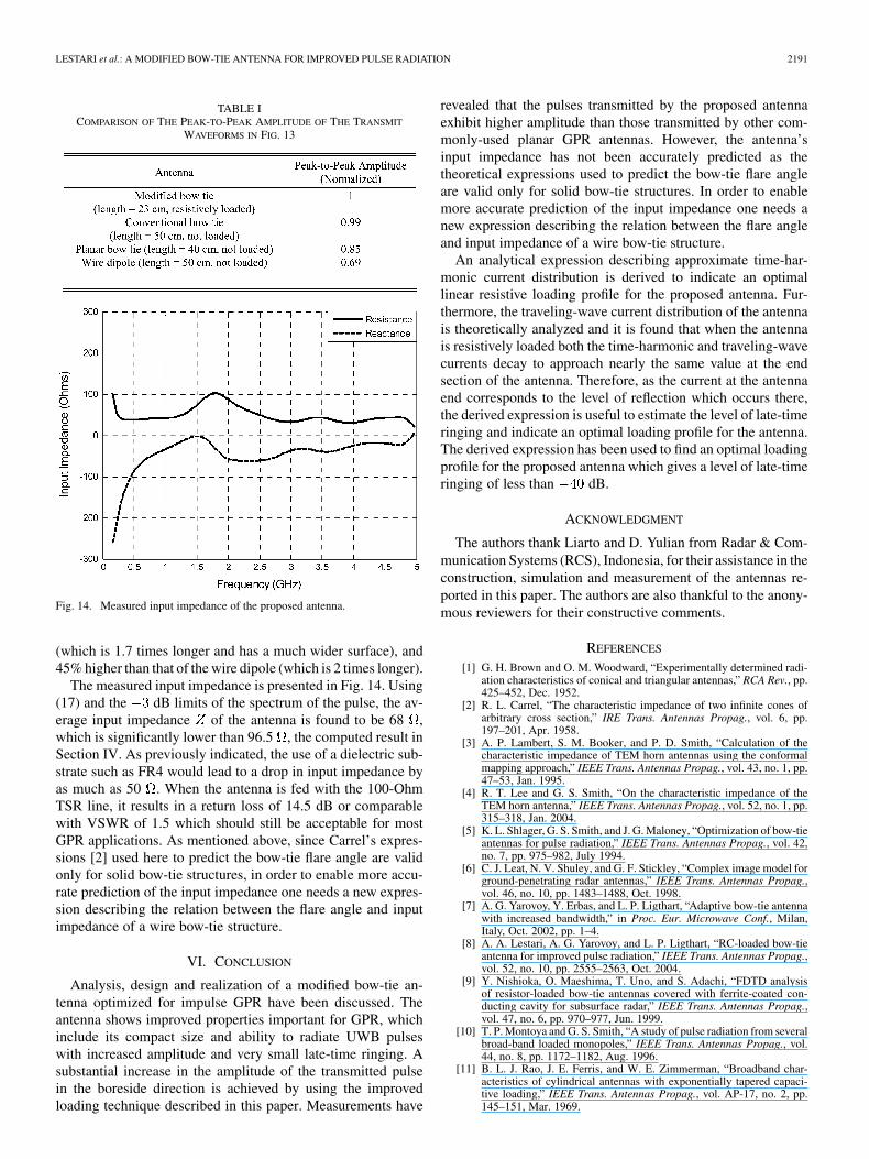
Fig. 8. Computed time-domain radiation pattern of the proposed antenna forexcitation with the monocycle in Fig. 1 at a distance of 1 m from the antenna.
a wire bow-tie structure. Furthermore, for pulse transmission itis advisable to introduce the average impedance given by [20]
(17)
where is the normalized spectrum of the exciting pulse, isthe input impedance of the antenna and and are the upperand lower limit of the spectrum of the pulse, respectively. isuseful to obtain the input reflection at the feed point of an an-tenna excited with transient pulses. It was demonstrated in [20]that for this purpose one may assume over the range
. Thus, using (17), the dB upper and lowerlimits of the spectrum of the exciting 0.8 ns monocycle (respec-tively 1.67 GHz and 420 MHz), and the mentioned assumption,we obtain for the wire model of the proposed an-tenna. This result shows a nearly match termination with the100-Ohm TSR feed line. However, we note that as the modeldoes not include any dielectric substrate, we may expect to seea smaller value of the average input impedance when real-izing the antenna on a dielectric material.
Additionally, Fig. 8 presents the computed time-domain radi-ation pattern of the proposed antenna. The plotted radiation pat-tern represents the peak-to-peak amplitude of the pulses trans-mitted by the antenna in the indicated directions. The traditional(frequency-domain) radiation patterns are less useful for pulseradiating antennas as they do not directly give a measure for thestrength of the pulses radiated by the antenna. The radiation pat-tern is computed at a distance of 1 m since in the aimed high-res-olution GPR applications the targets are mostly located at a veryclose range from the antenna, from a few cm to less than 1 m.
V. MEASUREMENTS
An experimental antenna with chip resistors for the loadinghas been constructed as a printed antenna on an FR4 material asshown in Fig. 9. Measurements of input impedance and trans-mitted pulses were carried out using the technique introduced in[15] which employs a TSR line to feed the antenna, and in [16]
2190 IEEE TRANSACTIONS ON ANTENNAS AND PROPAGATION, VOL. 58, NO. 7, JULY 2010
Fig. 9. Experimental antenna constructed as a printed antenna on an FR4material.
Fig. 10. Setup for pulse radiation measurement.
Fig. 11. Transmit waveform of the experimental antenna at a distance of 1 min the boreside direction.
which employs a UWB shielded loop antenna [21] as a probe,respectively. The antenna was fed with a TSR line which wasconnected to a generator exciting the pulse in Fig. 1 accordingto the setup depicted in Fig. 10. The measurements were carriedout in a non reflection-free room by paying attention to the dis-tance from the antenna to the closest surrounding objects. Theemployed post-processing scheme of the measured data, whichincludes time windowing to exclude unwanted reflections fromthe surroundings and a deconvolution procedure to compensatefor the probe’s characteristics, is given in detail in [15] and [16].The measured transmit waveform of the experimental antennais plotted in Fig. 11 where good agreement with the computedwaveform is observed. It is shown that the pulse transmitted
Fig. 12. Scaled geometries of different antennas for comparison purposes.From top: the modified bow-tie antenna (������ � � cm, resistively loaded),a conventional solid bow-tie antenna (������ � � cm, flare ����� � � ,not loaded), a planar dipole (������ � �� cm, ����� � � cm, not loaded),and a wire dipole (������ � � cm, not loaded).
Fig. 13. Comparison of the measured transmit waveforms (at a distance of 1 min boreside direction) of the antennas shown in Fig. 12.
by the antenna exhibits a level of late-time ringing lower thandB below the peak of the pulse after less than 3 times the
pulse duration, which agrees with the computed result.To verify the antenna’s improved characteristic for pulse radi-
ation, we perform a comparison between the proposed antennaand several other commonly-used GPR antennas, i.e., a conven-tional solid bow tie, a planar dipole and a wire dipole. Scaledgeometries of these antennas are shown in Fig. 12 where canbe seen that the size of the proposed antenna is significantlysmaller relative to the others due to the use of FR4. The reasonfor choosing the 50 cm length for the conventional bow tie andwire dipole has been explained in Section IV. The measuredtransmit waveforms of these antennas are presented in Fig. 13and a comparison of their peak-to-peak amplitudes is given inTable I. It is obvious that despite its relatively small size the pro-posed antenna exhibits the highest peak-to-peak amplitude. Thewaveform amplitude of the proposed antenna is slightly higherthan that of the conventional bow tie (which has considerablylarger dimensions), 18% higher than that of the planar dipole
LESTARI et al.: A MODIFIED BOW-TIE ANTENNA FOR IMPROVED PULSE RADIATION 2191
TABLE ICOMPARISON OF THE PEAK-TO-PEAK AMPLITUDE OF THE TRANSMIT
WAVEFORMS IN FIG. 13
Fig. 14. Measured input impedance of the proposed antenna.
(which is 1.7 times longer and has a much wider surface), and45% higher than that of the wire dipole (which is 2 times longer).
The measured input impedance is presented in Fig. 14. Using(17) and the dB limits of the spectrum of the pulse, the av-erage input impedance of the antenna is found to be 68 ,which is significantly lower than 96.5 , the computed result inSection IV. As previously indicated, the use of a dielectric sub-strate such as FR4 would lead to a drop in input impedance byas much as 50 . When the antenna is fed with the 100-OhmTSR line, it results in a return loss of 14.5 dB or comparablewith VSWR of 1.5 which should still be acceptable for mostGPR applications. As mentioned above, since Carrel’s expres-sions [2] used here to predict the bow-tie flare angle are validonly for solid bow-tie structures, in order to enable more accu-rate prediction of the input impedance one needs a new expres-sion describing the relation between the flare angle and inputimpedance of a wire bow-tie structure.
VI. CONCLUSION
Analysis, design and realization of a modified bow-tie an-tenna optimized for impulse GPR have been discussed. Theantenna shows improved properties important for GPR, whichinclude its compact size and ability to radiate UWB pulseswith increased amplitude and very small late-time ringing. Asubstantial increase in the amplitude of the transmitted pulsein the boreside direction is achieved by using the improvedloading technique described in this paper. Measurements have
revealed that the pulses transmitted by the proposed antennaexhibit higher amplitude than those transmitted by other com-monly-used planar GPR antennas. However, the antenna’sinput impedance has not been accurately predicted as thetheoretical expressions used to predict the bow-tie flare angleare valid only for solid bow-tie structures. In order to enablemore accurate prediction of the input impedance one needs anew expression describing the relation between the flare angleand input impedance of a wire bow-tie structure.
An analytical expression describing approximate time-har-monic current distribution is derived to indicate an optimallinear resistive loading profile for the proposed antenna. Fur-thermore, the traveling-wave current distribution of the antennais theoretically analyzed and it is found that when the antennais resistively loaded both the time-harmonic and traveling-wavecurrents decay to approach nearly the same value at the endsection of the antenna. Therefore, as the current at the antennaend corresponds to the level of reflection which occurs there,the derived expression is useful to estimate the level of late-timeringing and indicate an optimal loading profile for the antenna.The derived expression has been used to find an optimal loadingprofile for the proposed antenna which gives a level of late-timeringing of less than dB.
ACKNOWLEDGMENT
The authors thank Liarto and D. Yulian from Radar & Com-munication Systems (RCS), Indonesia, for their assistance in theconstruction, simulation and measurement of the antennas re-ported in this paper. The authors are also thankful to the anony-mous reviewers for their constructive comments.
REFERENCES
[1] G. H. Brown and O. M. Woodward, “Experimentally determined radi-ation characteristics of conical and triangular antennas,” RCA Rev., pp.425–452, Dec. 1952.
[2] R. L. Carrel, “The characteristic impedance of two infinite cones ofarbitrary cross section,” IRE Trans. Antennas Propag., vol. 6, pp.197–201, Apr. 1958.
[3] A. P. Lambert, S. M. Booker, and P. D. Smith, “Calculation of thecharacteristic impedance of TEM horn antennas using the conformalmapping approach,” IEEE Trans. Antennas Propag., vol. 43, no. 1, pp.47–53, Jan. 1995.
[4] R. T. Lee and G. S. Smith, “On the characteristic impedance of theTEM horn antenna,” IEEE Trans. Antennas Propag., vol. 52, no. 1, pp.315–318, Jan. 2004.
[5] K. L. Shlager, G. S. Smith, and J. G. Maloney, “Optimization of bow-tieantennas for pulse radiation,” IEEE Trans. Antennas Propag., vol. 42,no. 7, pp. 975–982, July 1994.
[6] C. J. Leat, N. V. Shuley, and G. F. Stickley, “Complex image model forground-penetrating radar antennas,” IEEE Trans. Antennas Propag.,vol. 46, no. 10, pp. 1483–1488, Oct. 1998.
[7] A. G. Yarovoy, Y. Erbas, and L. P. Ligthart, “Adaptive bow-tie antennawith increased bandwidth,” in Proc. Eur. Microwave Conf., Milan,Italy, Oct. 2002, pp. 1–4.
[8] A. A. Lestari, A. G. Yarovoy, and L. P. Ligthart, “RC-loaded bow-tieantenna for improved pulse radiation,” IEEE Trans. Antennas Propag.,vol. 52, no. 10, pp. 2555–2563, Oct. 2004.
[9] Y. Nishioka, O. Maeshima, T. Uno, and S. Adachi, “FDTD analysisof resistor-loaded bow-tie antennas covered with ferrite-coated con-ducting cavity for subsurface radar,” IEEE Trans. Antennas Propag.,vol. 47, no. 6, pp. 970–977, Jun. 1999.
[10] T. P. Montoya and G. S. Smith, “A study of pulse radiation from severalbroad-band loaded monopoles,” IEEE Trans. Antennas Propag., vol.44, no. 8, pp. 1172–1182, Aug. 1996.
[11] B. L. J. Rao, J. E. Ferris, and W. E. Zimmerman, “Broadband char-acteristics of cylindrical antennas with exponentially tapered capaci-tive loading,” IEEE Trans. Antennas Propag., vol. AP-17, no. 2, pp.145–151, Mar. 1969.

2192 IEEE TRANSACTIONS ON ANTENNAS AND PROPAGATION, VOL. 58, NO. 7, JULY 2010
[12] A. A. Lestari, A. G. Yarovoy, and L. P. Ligthart, “Capacitively-taperedbowtie antenna,” in Proc. Millennium Conf. Antennas Propag., Davos,Switzerland, Apr. 2000, pp. 1–4.
[13] A. A. Lestari, A. G. Yarovoy, and L. P. Ligthart, “Adaptive wire bow-tieantenna for GPR applications,” IEEE Trans. Antennas Propag., vol. 53,no. 5, pp. 1745–1754, May 2005.
[14] A. A. Lestari, “Antennas for improved ground penetrating radar: mod-eling tools, analysis and design,” Ph.D. dissertation, Delft Univ. Tech-nology, Delft, The Netherlands, 2003.
[15] A. A. Lestari, A. G. Yarovoy, and L. P. Ligthart, “Ground influence onthe input impedance of transient dipole and bow-tie antennas,” IEEETrans. Antennas Propag., vol. 52, no. 8, pp. 1970–1975, Aug. 2004.
[16] A. A. Lestari, A. B. Suksmono, A. Kurniawan, E. Bharata, A. G.Yarovoy, and L. P. Ligthart, “A facility for UWB antenna measure-ments in time domain,” in Proc. IEEE Int. Workshop Antenna Tech.,Singapore, Mar. 2005, pp. 109–112.
[17] T. T. Wu and R. W. P. King, “The cylindrical antenna with nonre-flecting resistive loading,” IEEE Trans. Antennas Propag., vol. AP-13,pp. 369–373, May 1965.
[18] G. J. Burke and A. J. Poggio, “Numerical Electromagnetic Code(NEC)—Method of Moments, Part I: Theory,” NOSC TD-116, NavalOcean Syst. Center. San Diego, CA, Jan. 1980.
[19] C. M. Butler, “The equivalent radius of a narrow conducting strip,”IEEE Trans. Antennas Propag., vol. 30, no. 4, Jul. 1982.
[20] R. W. P. King and H. J. Schmitt, “The transient response of linear an-tennas and loops,” IRE Trans. Antennas Propag., vol. 10, pp. 222–228,May 1962.
[21] A. Yarovoy, R. de Jongh, and L. Ligthart, “Ultra-wideband sensor forelectromagnetic field measurements in time domain,” Electr. Lett., vol.36, no. 20, pp. 1679–1680, Sep. 2000.
Andrian Andaya Lestari (M’08) was born inBogor, Indonesia. He received the M.Sc. (Ingenieur)and Ph.D. degrees in electrical engineering fromDelft University of Technology, The Netherlands, in1993 and 2003, respectively.
From 1993 to 1998, he was with a government re-search agency in Jakarta, Indonesia. He joined the In-ternational Research Centre for Telecommunicationsand Radar (IRCTR) - Delft University of Technology,in 1998. In 2006, he became the Director of the In-donesian Branch of IRCTR (IRCTR-IB) at Bandung
Institute of Technology (ITB), Indonesia. He has authored or coauthored over 90publications, which include patents, technical reports, presentations and articlespresented in journals and conferences. His research interests include antennasand radar systems. Currently he is working on the development of the Indone-sian maritime radar INDERA.
Endon Bharata received the B.Sc. and M.Eng. de-grees in telecommunication engineering from Ban-dung Institute of Technology (ITB), Indonesia.
He worked for some private companies as a radiocommunication expert between 1980 and 2000. Heis currently an Associate Professor at the School ofElectrical Engineering and Informatics, BandungInstitute of Technology, Indonesia. His researchinterest covers communication electronics andmicrowave, antennas, and communication systems.
Andriyan Bayu Suksmono (M’02–SM’08) receivedthe B.S. degree in physics and the M.S. degree inelectrical engineering from the Bandung Institute ofTechnology (ITB), Indonesia, and the Ph.D. degreein engineering from the University of Tokyo, Japan,in 1990, 1996 and 2002, respectively.
He joined ITB as an Instructor (1996–2005),Associate Professor (2005–2009), and Professor(2009-present) at the School of Electrical Engi-neering and Informatics, ITB. His main researchinterests are signal processing and imaging.
Dr. Suksmono is a Professional Member of the ACM. He has beengranted several international research funds, scholarships, and fellowship,from RCAST—Tokyo University, Monbukagakusho, JSPS, AIGRP, and theHitachi Foundation. In 2004, he was awarded the Best Paper in TheoreticalDevelopment by APNNA for his work in spatio-temporal ultra-widebandneuro-beamforming. He was the recipient of the Outstanding Faculty Awardof ITB and the Republic of Indonesia in June 2007 and August 2007,respectively.
Adit Kurniawan graduated from the Bandung In-stitute of Technology (ITB), Indonesia, in 1986 andreceived the M.Eng. degree from RMIT, Australia,in 1996 and the Ph.D. degree from the University ofSouth Australia, in 2003, both in telecommunicationengineering.
He became a faculty member of the Departmentof Electrical Engineering, ITB, in 1990. His researchinterests are antenna and wave propagation, cellularcommunication system, and radio communication.He is currently an Associate Professor and serves
as the Head of Telecommunication Engineering Department at the BandungInstitute of Technology.
Alexander G. Yarovoy (M’96–SM’04) graduatedwith the Diploma (with honors) in radiophysics andelectronics and received the Cand. Phys. Math. Sci.and Dr. Phys. Math. Sci. degrees in radiophysics allfrom Kharkov State University, Ukraine, in 1984,1987, and 1994, respectively.
In 1987, he joined the Department of Radio-physics, Kharkov State University, as a Researcherand became a Professor in 1997. From September1994 through 1996, he was with the TechnicalUniversity of Ilmenau, Germany, as a Visiting
Researcher. Since 1999, he is with the International Research Centre forTelecommunications and Radar (IRCTR), Delft University of Technology,The Netherlands, where he coordinates all UWB-related projects. His mainresearch interests are in ultrawideband (UWB) technology and its applications(in particular, UWB radars) and applied electromagnetics (in particular, UWBantennas).
Prof. Yarovoy is the recipient of a 1996 International Union of Radio Science(URSI) “Young Scientists Award” and co-recipient of the European MicrowaveWeek Radar Award in 2001 for the Paper that Best Advances the State-of-the-Artin Radar Technology. He served as the Co-Chairman and the Technical ProgramCommittee Chair of the 10th International Conference on Ground PenetratingRadar (GPR2004), Delft, and the Secretary of the 1st European Radar Confer-ence (EuRAD’04), Amsterdam, The Netherlands.
Leo P. Ligthart (M’94–SM’95–F’02) was bornin Rotterdam, the Netherlands, on September 15,1946. He received the Engineer’s degree (cumlaude) and the Ph.D. degree from Delft Universityof Technology, The Netherlands, in 1969 and 1985,respectively, and the Doctorates (honoris causa)from Moscow State Technical University of CivilAviation and Tomsk State University of ControlSystems and Radioelectronics, Russia, in 1999 and2001, respectively.
Since 1992, he has held the Chair of MicrowaveTransmission, Radar and Remote Sensing in the Department of Electrical Engi-neering, Mathematics and Computer Science, Delft University of Technology.In 1994, he became Director of the International Research Centre for Telecom-munications and Radar (IRCTR). His principal areas of specialization includeantennas and propagation, radar and remote sensing. He has also been active insatellite, mobile and radio communications. He has written over 400 papers andtwo radar books.
Prof. Ligthart is an Academician of the Russian Academy of Transport anda Fellow of the Institute of Electrical and Electronics Engineers (IEEE) and theInstitute of Engineering and Technology (IET), London, U.K.
Related Documents