Promet – Traffic&Transportation, Vol. 24, 2012, No. 2, 125-134 125 D. Martinović, M. Tudor, D. Bernečić: A Model of Ship Auxiliary System for Reliable Ship Propulsion DRAGAN MARTINOVIĆ, Ph.D. E-mail: [email protected] MATO TUDOR, Ph.D. E-mail: [email protected] DEAN BERNEČIĆ, Ph.D. E-mail: [email protected] University of Rijeka, Faculty of Maritime Studies Studentska 2, 51000 Rijeka, Croatia Transport Engineering Preliminary Communication Accepted: June 11, 2011 Approved: Mar. 14, 2012 A MODEL OF SHIP AUXILIARY SYSTEM FOR RELIABLE SHIP PROPULSION ABSTRACT The main purpose of a vessel is to transport goods and passengers at minimum cost. Out of the analysis of relevant global databases on ship machinery failures, it is obvious that the most frequent failures occur precisely on the gener- ator-running diesel engines. Any failure in the electrical sys- tem can leave the ship without propulsion, even if the main engine is working properly. In that case, the consequences could be devastating: higher running expenses, damage to the ship, oil spill or substantial marine pollution. These are the reasons why solutions that will prevent the ship being unable to manoeuvre during her exploitation should be im- plemented. Therefore, it is necessary to define a propulsion restoration model which would not depend on the primary electrical energy. The paper provides a model of the marine auxiliary system for more reliable propulsion. This includes starting, reversing and stopping of the propulsion engine. The proposed solution of reliable propulsion model based on the use of a shaft generator and an excitation engine enables the restoration of propulsion following total failure of the electrical energy primary production system, and the self-propelled ship navigation. A ship is an important factor in the Technology of Transport, and the implementation of this model increases safety, reduces downtime, and signifi- cantly decreases hazards of pollution damage. KEYWORDS reliable propulsion, failure, ship auxiliary system, control, propulsion restoration 1. INTRODUCTION International shipping companies are exposed to increased costs of uncertainty and fierce competition, which is why they are forced to constantly improve the quality of services while reducing the effective cost. The most important factor in Maritime Transport Tech- nology is safety of navigation, which mostly depends on the safety of the ship [2]. In the worst case sce- nario, a failure of the propulsion system and inability to manoeuvre can lead to damaging of the ship, oil spill and substantial pollution. Due to the fact that the safety of the vessel and its operation are mainly influ- enced by technology and the ship crew, the latter being a large financial burden placed on the ship-owner, a continuous trend of reducing the crew number is tak- ing place. In addition, it is difficult to acquire expertise in maintenance of modern marine systems, because it is not easily transmitted to another crew member. On the other hand, permanent introduction of new tech- nologies in the field of ships design brings further dif- ficulties within the maintenance process. The possible failure and cancellation of auxiliary engines lead to a serious threat to the safety of the ship. In many cases, the cost of process interruptions due to failure of the device multiply exceeds the in- vestment cost of the device. The consequence of this situation is stopping of the ship propulsion although the emergency generator is in operation. Meanwhile, the ship floats adrift at sea, and left to external condi- tions cannot be controlled by crew members. Electric power is being diagnosed, which includes testing of process equipment, together with power production, distribution and conversion checking (power engines, generators, switches, converters, motors, etc.). Await- ing repair of diesel generators can take very long, and sometimes the ship must be towed to the nearest port. Instead of requesting towage of the boat, as re- sult of the fact that there is no electricity production, a system that will automatically supply all equipment necessary for the propulsion of the engine auxiliary system can be provided, thereby providing ship propul- sion. The installation of such a system is the best way to increase reliability [17] and availability of the propul- sion complex and the ship as a whole. Due attention has not been paid to this problem because of the lack of data on failures, towages and losses incurred due to malfunction of the generator, since the companies are reluctant to provide the public with such informa-

Welcome message from author
This document is posted to help you gain knowledge. Please leave a comment to let me know what you think about it! Share it to your friends and learn new things together.
Transcript
Promet – Traffic&Transportation, Vol. 24, 2012, No. 2, 125-134 125
D. Martinović, M. Tudor, D. Bernečić: A Model of Ship Auxiliary System for Reliable Ship Propulsion
DRAGAN MARTINOVIĆ, Ph.D.E-mail: [email protected] MATO TUDOR, Ph.D.E-mail: [email protected] DEAN BERNEČIĆ, Ph.D.E-mail: [email protected] University of Rijeka, Faculty of Maritime Studies Studentska 2, 51000 Rijeka, Croatia
Transport Engineering Preliminary Communication
Accepted: June 11, 2011 Approved: Mar. 14, 2012
A MODEL OF SHIP AUXILIARY SYSTEM FOR RELIABLE SHIP PROPULSION
ABSTRACT
The main purpose of a vessel is to transport goods and passengers at minimum cost. Out of the analysis of relevant global databases on ship machinery failures, it is obvious that the most frequent failures occur precisely on the gener-ator-running diesel engines. Any failure in the electrical sys-tem can leave the ship without propulsion, even if the main engine is working properly. In that case, the consequences could be devastating: higher running expenses, damage to the ship, oil spill or substantial marine pollution. These are the reasons why solutions that will prevent the ship being unable to manoeuvre during her exploitation should be im-plemented. Therefore, it is necessary to define a propulsion restoration model which would not depend on the primary electrical energy. The paper provides a model of the marine auxiliary system for more reliable propulsion. This includes starting, reversing and stopping of the propulsion engine. The proposed solution of reliable propulsion model based on the use of a shaft generator and an excitation engine enables the restoration of propulsion following total failure of the electrical energy primary production system, and the self-propelled ship navigation. A ship is an important factor in the Technology of Transport, and the implementation of this model increases safety, reduces downtime, and signifi-cantly decreases hazards of pollution damage.
KEYWORDS
reliable propulsion, failure, ship auxiliary system, control, propulsion restoration
1. INTRODUCTION
International shipping companies are exposed to increased costs of uncertainty and fierce competition, which is why they are forced to constantly improve the quality of services while reducing the effective cost. The most important factor in Maritime Transport Tech-nology is safety of navigation, which mostly depends on the safety of the ship [2]. In the worst case sce-nario, a failure of the propulsion system and inability
to manoeuvre can lead to damaging of the ship, oil spill and substantial pollution. Due to the fact that the safety of the vessel and its operation are mainly influ-enced by technology and the ship crew, the latter being a large financial burden placed on the ship-owner, a continuous trend of reducing the crew number is tak-ing place. In addition, it is difficult to acquire expertise in maintenance of modern marine systems, because it is not easily transmitted to another crew member. On the other hand, permanent introduction of new tech-nologies in the field of ships design brings further dif-ficulties within the maintenance process.
The possible failure and cancellation of auxiliary engines lead to a serious threat to the safety of the ship. In many cases, the cost of process interruptions due to failure of the device multiply exceeds the in-vestment cost of the device. The consequence of this situation is stopping of the ship propulsion although the emergency generator is in operation. Meanwhile, the ship floats adrift at sea, and left to external condi-tions cannot be controlled by crew members. Electric power is being diagnosed, which includes testing of process equipment, together with power production, distribution and conversion checking (power engines, generators, switches, converters, motors, etc.). Await-ing repair of diesel generators can take very long, and sometimes the ship must be towed to the nearest port.
Instead of requesting towage of the boat, as re-sult of the fact that there is no electricity production, a system that will automatically supply all equipment necessary for the propulsion of the engine auxiliary system can be provided, thereby providing ship propul-sion. The installation of such a system is the best way to increase reliability [17] and availability of the propul-sion complex and the ship as a whole. Due attention has not been paid to this problem because of the lack of data on failures, towages and losses incurred due to malfunction of the generator, since the companies are reluctant to provide the public with such informa-
D. Martinović, M. Tudor, D. Bernečić: A Model of Ship Auxiliary System for Reliable Ship Propulsion
126 Promet – Traffic&Transportation, Vol. 24, 2012, No. 2, 125-134
tion. The greatest problem of the calculation of failure odds is the inability to predict where and when it will happen, since a fault may happen at any time and in any place [9]. The occurrence of failure during the eco-nomic life of the ship changes its cost value.
Studies on modelling the marine auxiliary systems with respect to the safety of the ship propulsion are undoubtedly very complex, both theoretically and prac-tically, especially since the ship’s energy system itself is a very complicated organizational and technical sys-tem [10, 11, 15]. In most cases the dynamic changes of energy and information flows affect the safety of the ship energy system. Energy and information parame-ters are complex, nonlinear, highly automated and very expensive. Meanwhile, they are susceptible to possibly extreme operating conditions, which thereby threaten the navigation of the ship, ship safety, and even the ship in general. It is obvious that real-time experi-ments are not possible in such a situation. Therefore, scientific studies of dynamic behaviour are necessarily conducted on model systems. It is necessary to define appropriate models which will allow analyzing dynamic behaviour of the system and defining the optimal ship energy safety system, whilst keeping material invest-ment at a low level, without threat to the reality.
2. MODEL OF RELIABLE PROPULSION
The previous analysis [1, 12] acknowledges the lack of reliability of the marine machinery in case of failure of diesel generators or power failure onboard. According to regulations of ship registers, any ship with its own propulsion must have its own source of elec-tricity in case of emergency. If there is no electric ten-sion in the buses of the main switchboard, that source brings power to the most important appliances.
Onboard larger cargo ships, it is necessary to pro-vide permanent emergency power supply for at least 18 hours for: steering systems, emergency lighting, po-sition lights, radio equipment, navigation equipment, internal connection facilities, fire alarm systems, to-gether with additional consumers, if requested by the register (such as the bilge pump, fire pump, etc.). A die-sel generator should be used as a source of electricity in case of emergency. If there is the main board black-out, it must start working automatically and connect to the emergency switchboard, thereby taking over the load for the abovementioned consumers within 45 seconds. Reliable running of the generator should be ensured as well, by means of providing a sufficient supply of energy for at least three consecutive starts. Additionally, an alternative starting method should be available, for instance starting by hand or using an-other source of energy, which must be able to provide power for at least three consecutive starting of diesel generators within 30 minutes. The necessary equip-
ment and the diesel set should be placed in the room located above the highest continuous deck and above the engine hatch. The room door should be directed towards the open deck and should be placed next to the rooms containing major sources of electricity.
One of the possibilities for increasing reliability of the ship machine complex, which is almost self-evident, is to increase the power of emergency diesel generator. Its purpose is to obtain energy required to start and maintain the propulsion system engine [18]. This particular solution would be very easy. Thus it was implemented on several types of ships constructed in domestic shipyards. After thorough analysis, the afore-mentioned solution was rejected [1].
The application of the model to the reference ship Zrinski [5] leads to the following results. The table, which displays the electrical consumption balance, shows that the diesel generator in emergency should provide 204kW of power. Therefore, “MAN B & W” diesel engine type DO 226 MTE was chosen. It is a 1,800 min-1 four stroke engine generating necessary power through the voltage of 450V (3 phase), with a frequency of 60Hz. In the case of power failure on-board, the propulsion engines stop running. To start the engine again, it is necessary to run the required appliances. It takes 235.4kW. An engine generating 440kW should be installed to meet the registry regula-tion for emergency diesel generator, which represents more than twice the amount of power installed and re-quires a much larger generator. As the engine must be able to work for at least 28 continuous hours, it would be necessary to install a tank for approximately 2,000 litres of fuel oil. All of that should be placed in a sepa-rate room, which must be adequately insulated from noise and vibration. Naturally, such a unit is harder to run, especially if the possibility of alternative manual startup is taken into account. All of this complicates a seemingly simple solution. Nevertheless, the main advantage of this solution – largely increased reliabil-ity – remains untouched. The only question is whether another acceptable solution exists that would lead to the same result.
The previous analysis brought us to the conclusion that the proposed system must be part of a highly in-tegrated propulsion system, rather than a separate unit. A major drawback of the solution including diesel emergency generator is the large distance between the generator room and the engine room.
Hence the solution proposed must be adapted to the characteristics of the propulsion engine as well as the requirements of the installation cost, maintenance cost [4] and ship vacancy cost.
Establishing electric load balance for starting and normal operation of the main engine is the first step that needs to be undertaken. After analyzing auxil-iary systems of two-stroke diesel engines [7, 8, 13] designed by leading companies (MAN B&W, Wärtsila
Promet – Traffic&Transportation, Vol. 24, 2012, No. 2, 125-134 127
D. Martinović, M. Tudor, D. Bernečić: A Model of Ship Auxiliary System for Reliable Ship Propulsion
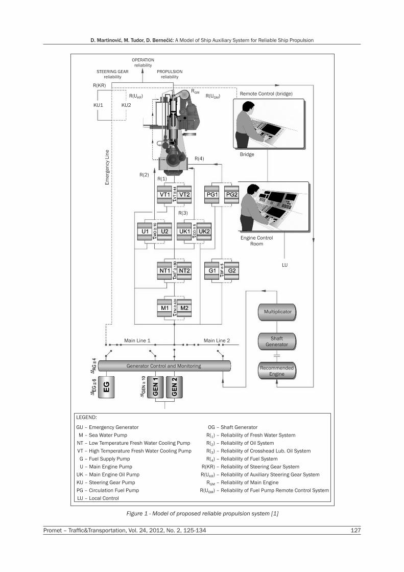
LEGEND:
GU – Emergency Generator
M – Sea Water Pump
NT – Low Temperature Fresh Water Cooling Pump
VT – High Temperature Fresh Water Cooling Pump
G – Fuel Supply Pump
U – Main Engine Pump
UK – Main Engine Oil Pump
KU – Steering Gear Pump
PG – Circulation Fuel Pump
LU – Local Control
OG – Shaft Generator
R( ) – Reliability of Fresh Water System1
R( ) – Reliability of Oil System2
R( ) – Reliability of Crosshead Lub. Oil System3
R( ) – Reliability of Fuel System4
R(KR) – Reliability of Steering Gear System
R(U ) – Reliability of Auxiliary Steering Gear SystemKR
R – Reliability of Main EngineGM
R(U ) – Reliability of Fuel Pump Remote Control SystemGM
OPERATION
reliability
STEERING GEAR
reliability
R(KR)
KU1 KU2
PROPULSION
reliability
R(U )KR R(U )GM
RGM Remote Control (bridge)
BridgeR(4)
R(2)
R(3)
R(1)
Engine Control
Room
LU
Em
erg
en
cy L
ine
Main Line 1 Main Line 2
Generator Control and Monitoring
Multiplicator
Shaft
Generator
Recommended
Engine
Figure 1 - Model of proposed reliable propulsion system [1]
D. Martinović, M. Tudor, D. Bernečić: A Model of Ship Auxiliary System for Reliable Ship Propulsion
128 Promet – Traffic&Transportation, Vol. 24, 2012, No. 2, 125-134
- (Sulzer)), it becomes clear that it is possible to set up a unique model of the main engine auxiliary systems.
Consumers that must be supplied with electrical energy are the sea water pump (M), low temperature fresh water pump (LT), high temperature fresh water pump (HT), main engine lube oil pump (U), crosshead lubricating oil pump (UK), fuel oil supply pump (G) and fuel oil booster pump (PG). The required amount of fuel, lubricating oil, and flow of HT and LT fresh water and sea water are determined from the data given in the manufacturer’s catalogues. The calculated param-eters are used to produce power and flow diagrams. The power of the mentioned pumps can be determined from the diagrams.
The total power needed for the propulsion of the main engine auxiliary systems is:P = PM + PNT + PVT + PU + PUK + PG + PPG [kW]. (1)where: P - total power needed to run the propulsion
engine auxiliary systems, PM - power of sea water pump, PNT - power of low temperature fresh water
pump, PVT - power of high temperature fresh water
pump, PU - power of main engine lube oil pump, PUK - power of crosshead lubricating oil pump, PG - power of fuel oil booster pump, PPG - power of fuel oil supply pump.
The calculated power is used to define the auxiliary engine which is used as a backup in emergency situ-ations, to feed the main engine auxiliary systems and service the main engine. A classic design solution is a generator set, fitted with all the additional equipment. This, however, results in space issues, as additional foundations and stiffeners are required, as well as ad-ditional service space. In order to avoid some of these issues, the appropriate diesel engine could be coupled with the existing shaft generator, to be used only in cases of total power failure (Figure 1).
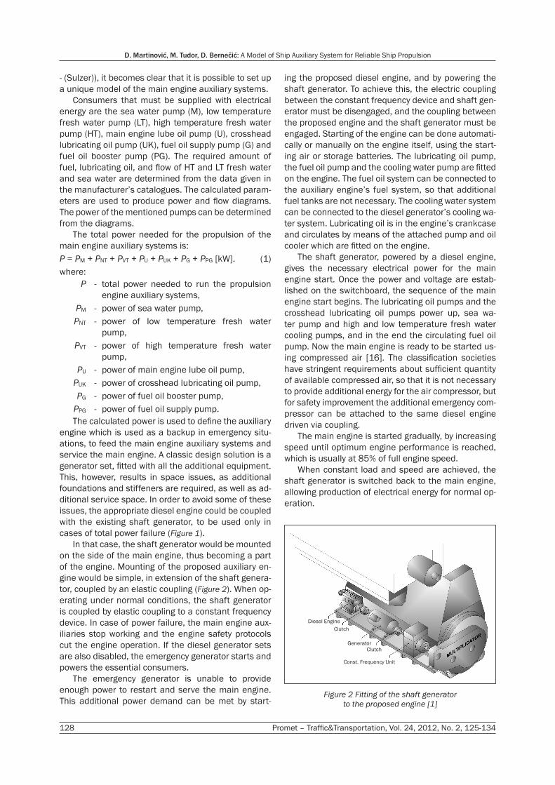
In that case, the shaft generator would be mounted on the side of the main engine, thus becoming a part of the engine. Mounting of the proposed auxiliary en-gine would be simple, in extension of the shaft genera-tor, coupled by an elastic coupling (Figure 2). When op-erating under normal conditions, the shaft generator is coupled by elastic coupling to a constant frequency device. In case of power failure, the main engine aux-iliaries stop working and the engine safety protocols cut the engine operation. If the diesel generator sets are also disabled, the emergency generator starts and powers the essential consumers.
The emergency generator is unable to provide enough power to restart and serve the main engine. This additional power demand can be met by start-
ing the proposed diesel engine, and by powering the shaft generator. To achieve this, the electric coupling between the constant frequency device and shaft gen-erator must be disengaged, and the coupling between the proposed engine and the shaft generator must be engaged. Starting of the engine can be done automati-cally or manually on the engine itself, using the start-ing air or storage batteries. The lubricating oil pump, the fuel oil pump and the cooling water pump are fitted on the engine. The fuel oil system can be connected to the auxiliary engine’s fuel system, so that additional fuel tanks are not necessary. The cooling water system can be connected to the diesel generator’s cooling wa-ter system. Lubricating oil is in the engine’s crankcase and circulates by means of the attached pump and oil cooler which are fitted on the engine.
The shaft generator, powered by a diesel engine, gives the necessary electrical power for the main engine start. Once the power and voltage are estab-lished on the switchboard, the sequence of the main engine start begins. The lubricating oil pumps and the crosshead lubricating oil pumps power up, sea wa-ter pump and high and low temperature fresh water cooling pumps, and in the end the circulating fuel oil pump. Now the main engine is ready to be started us-ing compressed air [16]. The classification societies have stringent requirements about sufficient quantity of available compressed air, so that it is not necessary to provide additional energy for the air compressor, but for safety improvement the additional emergency com-pressor can be attached to the same diesel engine driven via coupling.
The main engine is started gradually, by increasing speed until optimum engine performance is reached, which is usually at 85% of full engine speed.
When constant load and speed are achieved, the shaft generator is switched back to the main engine, allowing production of electrical energy for normal op-eration.
Diesel Engine
Clutch
Generator
Clutch
Const. Frequency Unit
Figure 2 Fitting of the shaft generator
to the proposed engine [1]

Promet – Traffic&Transportation, Vol. 24, 2012, No. 2, 125-134 129
D. Martinović, M. Tudor, D. Bernečić: A Model of Ship Auxiliary System for Reliable Ship Propulsion
For the mounting of the proposed system (Figure 2), apart from the already mentioned devices, it is neces-sary to extend the foundation of the shaft generator by the side of the propulsion engine. Thus, the entire system takes up very little space, which is a very im-portant factor in the complex ship engine room. This concept would be very convenient for operation and maintenance. The price of an additional plant is neg-ligible compared to the towing of a vessel in the event of failure of the existing facilities [1].
3. MANAGEMENT AND LOAD MODEL FOR THE PROPOSED SOLUTION
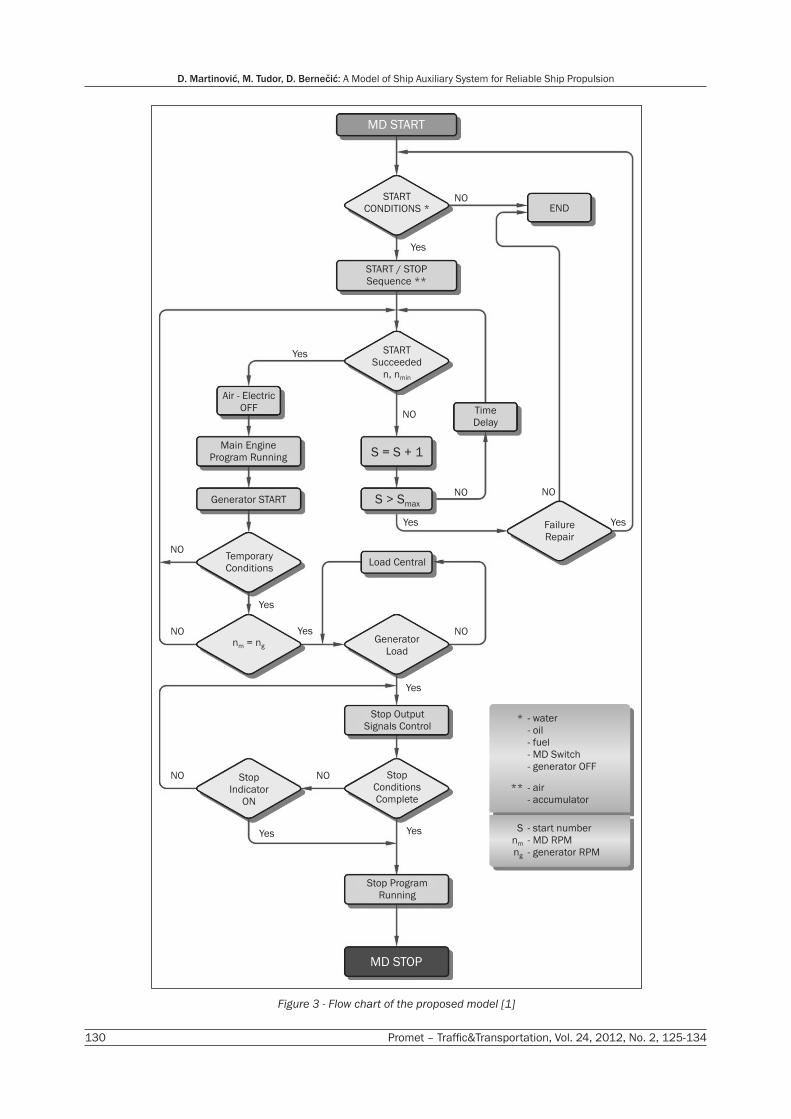
Compressed air or storage batteries are used for starting the engine. Starting can be done either au-tomatically or manually, which is in compliance with the regulations of the Register of Shipping. Since the proposed solution is new, it has not been considered by the Register yet (Figure 3).
The main program starts by initialising the manage-ment system and setting initial parameters. If there is a need for manual operation, the management and supervision system will only analyse parameters, con-trol diesel generator set and sound alarms.
Automatic control of the diesel generator units does not completely exclude manual controlling. All relevant functions of the ship’s electric switchboard must have manual control. After a successful engine start, the program will proceed with its normal engine operation mode.
The program is modelled to increase speed and check parameter values which are relevant for proper and safe operation. When the engine reaches the op-timum speed of rotation, the shaft generator, which is not subjected to any load at that moment, is actuated. There is a slight change in speed gradient. While in operation, the program checks the current engine con-ditions. If some of them are not met (low oil pressure, too high temperature of cooling water, etc.), the engine returns to a predefined security mode [6]. If, on the other hand, the conditions are met, normal operating mode is reinstated. After that, the speed regulation programme is actuated. The purpose of the regulation mode is to achieve equal engine speed nm and gener-ator speed ng. If the program fails to do so, the safety mode is restored.
Then follows the gradual loading of the genera-tor by adding consumers to the network. In doing so, particular attention must be paid to the synchroniza-tion and parallel operation of the diesel generator unit within the ship’s electric plant and networks, as well as to the adding of consumers. Consumers are added by singular synchronisation and frequency stabilisation must be ensured.
The basic requirements for the synchronization of the generator and parallel operation of the network
are the equalization of engine voltage um and gen-erator voltage ug, approximation of engine frequency fm and generator frequency fg, and the adjustment of voltage phase when consumers are switched from the network onto the generator power supply. This is achieved by changing the speed of engine rotation. The engine speed is changed by direct regulation of the fuel injection regulator. This, in turn is determined by the optimum load power. Therefore, the generator load must be arranged in a way that it can be regu-lated automatically and manually.
For this reason, power P1 must be adjustable, but within limits of the nominal operation mode. The next step of the program includes the speed regulation by means of an automatic regulator. This program con-stantly tests conditions for stopping (fault, error, ex-ceeding the limit values of critical load parameters, oil pressure, cooling water temperature, etc.). If any of the parameters are met, the program will automatically stop the operation of the engine.
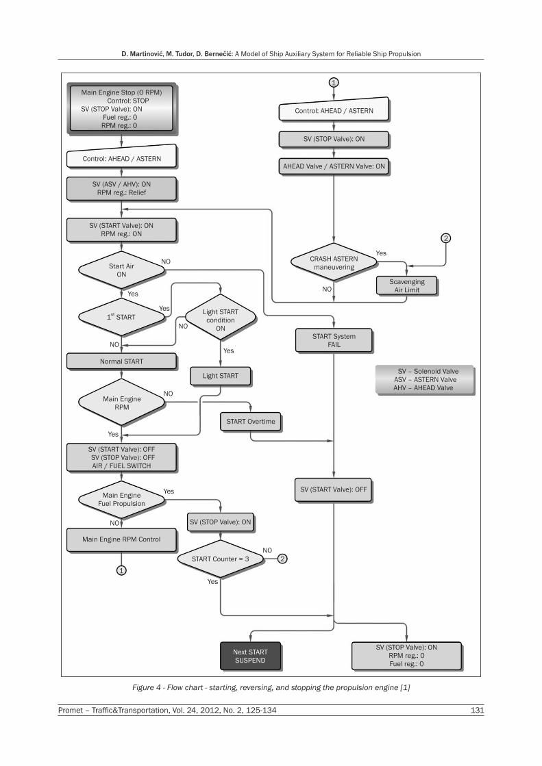
4. RESTARTING THE PROPULSION SYSTEM
For restarting the propulsion system, the main pro-pulsion engine must be started. Before this is done, it is necessary to check the auxiliary system parameters, i.e. oil system, cooling water, fuel oil and starting air pressure. Once these requirements are met, engine starting can commence. The algorithm for starting, re-versing, and stopping the engine (Figure 4) must antici-pate two ways of starting the engine. These are the so called easy start and normal start, which are automati-cally selected depending on the manoeuvrability. The starting period is completed when the operation of the propulsion unit is stabilised.
The shaft generator must be disengaged for nor-mal start. The electrical or mechanical governor controls the engine speed. For engaging the shaft generator and transferring to main engine and shaft generator for power supply, the optimum speed must be achieved. The engine load is linear and depends on the preheating of the cooling water and lubricating oil. The load ranges from 30% (adjustable) and 100% of maximum power. Whether the shaft generator is to be engaged, depends upon the maximum engine load, which is governed by a time component and can be regulated within the limits of 70-100%. For the select-ed load, a constant speed of propulsion engines for shaft generator operation is determined.
In the proposed model of alternative propulsion, when the engine speed varies within these limits, the shaft generator is connected through the gearing (mul-tiplicator) and a device that ensures constant rpm. If, for instance, change of engine rotation speed is be-tween 70 and 40%, due to manoeuvring operations, a linear change of the generator power production be-
D. Martinović, M. Tudor, D. Bernečić: A Model of Ship Auxiliary System for Reliable Ship Propulsion
130 Promet – Traffic&Transportation, Vol. 24, 2012, No. 2, 125-134
Figure 3 - Flow chart of the proposed model [1]
MD START
START
CONDITIONS *
NO
Yes
Yes
Yes
Yes
Yes Yes
Yes
Yes Yes
END
START / STOP
Sequence **
Time
DelayNO
NO
NO
NO NO
NO
NO
NO
START
Succeeded
n, nmin
Air - Electric
OFF
Main Engine
Program Running
Generator START
Temporary
Conditions
S = S + 1
S > Smax
Load Central
Failure
Repair
Generator
Loadn = nm g
Stop
Indicator
ON
Stop
Conditions
Complete
Stop Output
Signals Control
Stop Program
Running
MD STOP
- water
- oil
- fuel
- MD Switch
- generator OFF
- air
- accumulator
- start number
- MD RPM
- generator RPM
*
**
S
nm
ng
Promet – Traffic&Transportation, Vol. 24, 2012, No. 2, 125-134 131
D. Martinović, M. Tudor, D. Bernečić: A Model of Ship Auxiliary System for Reliable Ship Propulsion
Figure 4 - Flow chart - starting, reversing, and stopping the propulsion engine [1]
Main Engine Stop (0 RPM)
Control: STOP
SV (STOP Valve): ON
Fuel reg.: 0
RPM reg.: 0
Control: AHEAD / ASTERN
SV (ASV / AHV): ON
RPM reg.: Relief
SV (START Valve): ON
RPM reg.: ON
Start Air
ON
1 STARTst
NO
NO
NO
NO
Yes
Yes
Yes
Yes
Yes
NO
NO
Yes
Normal START
Light START
Light START
condition
ON
Main Engine
RPM
START Overtime
SV (START Valve): OFF
SV (STOP Valve): OFF
AIR / FUEL SWITCH
Main Engine
Fuel Propulsion
SV (STOP Valve): ON
Main Engine RPM Control
1
2START Counter = 3
Next START
SUSPEND
SV (STOP Valve): ON
RPM reg.: 0
Fuel reg.: 0
SV (START Valve): OFF
START System
FAIL
2
Yes
NO
CRASH ASTERN
maneuvering
Scavenging
Air Limit
1
Control: AHEAD / ASTERN
SV (STOP Valve): ON
AHEAD Valve / ASTERN Valve: ON
SV – Solenoid Valve
ASV – ASTERN Valve
AHV – AHEAD Valve
D. Martinović, M. Tudor, D. Bernečić: A Model of Ship Auxiliary System for Reliable Ship Propulsion
132 Promet – Traffic&Transportation, Vol. 24, 2012, No. 2, 125-134
tween 100 and 40% will be present as well [1]. The fact that at 40% of engine speed, the generator power is 40% is very significant for this design. This power would satisfy the electricity demand for essential main propulsion system auxiliaries. When the main engine speed changes in the range between 70 and 40%, the regulation of electricity consumption is very important. Less important consumers need to be shut off in due time, in order to enable operation of oil, fuel, freshwa-ter and seawater main engine systems. Should there be no power for emergency lighting and steering, the emergency generator is to be started.
After successfully starting and setting up the pro-pulsion, the parameters necessary for normal engine operation are checked and the engine load is gradual-ly increased until optimum efficiency is achieved. After stabilizing the system and speed, the main engine will drive the shaft generator.
The new generation of two-stroke slow-speed ma-rine diesel engines with electronic injection control and electronic control of exhaust valve operation have the possibilities to achieve optimum efficiency much faster, and to maintain the optimum exhaust gas tem-peratures regarding environment protection auxiliary equipment (SCR – Selective Catalytic Reduction). As a result there is a much faster restart of the ship’s power system [3].
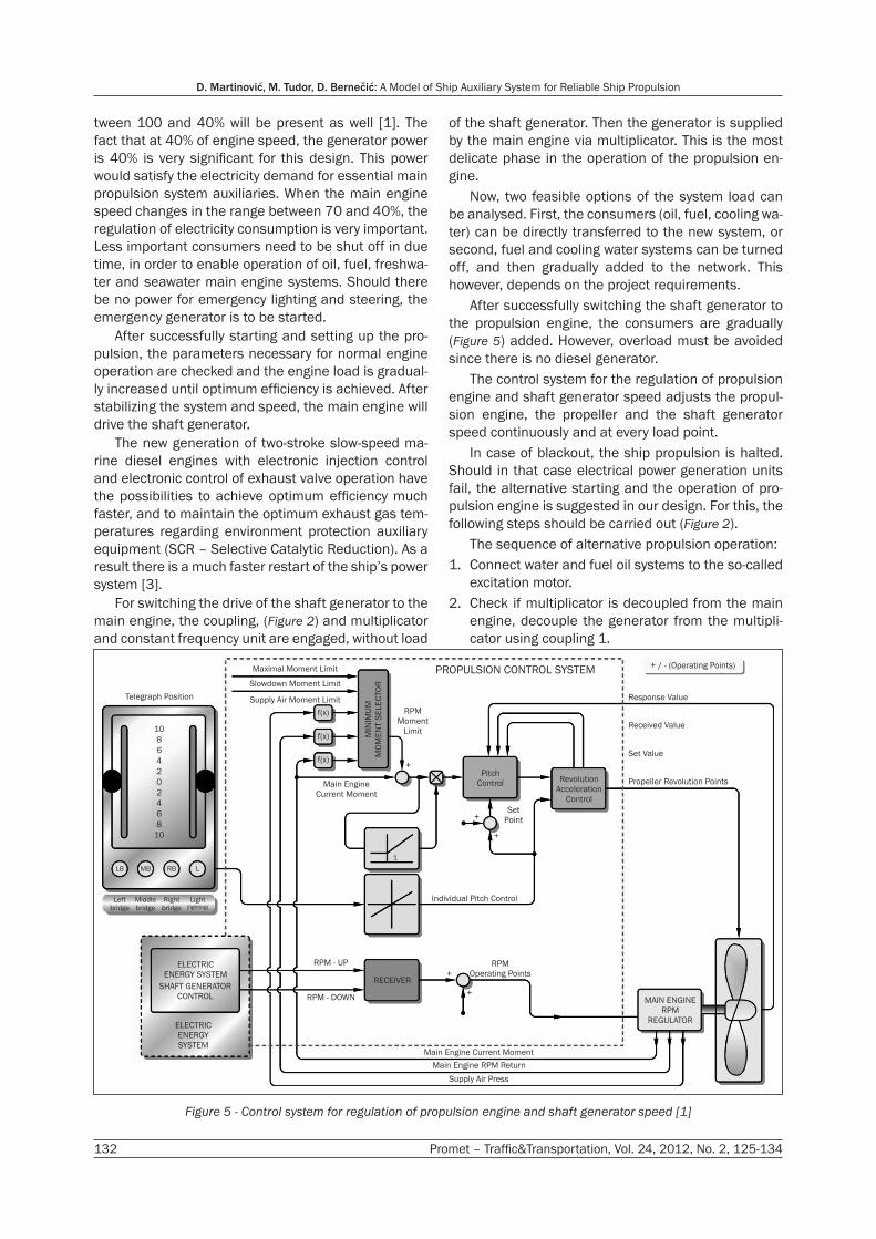
For switching the drive of the shaft generator to the main engine, the coupling, (Figure 2) and multiplicator and constant frequency unit are engaged, without load
of the shaft generator. Then the generator is supplied by the main engine via multiplicator. This is the most delicate phase in the operation of the propulsion en-gine.
Now, two feasible options of the system load can be analysed. First, the consumers (oil, fuel, cooling wa-ter) can be directly transferred to the new system, or second, fuel and cooling water systems can be turned off, and then gradually added to the network. This however, depends on the project requirements.
After successfully switching the shaft generator to the propulsion engine, the consumers are gradually (Figure 5) added. However, overload must be avoided since there is no diesel generator.
The control system for the regulation of propulsion engine and shaft generator speed adjusts the propul-sion engine, the propeller and the shaft generator speed continuously and at every load point.
In case of blackout, the ship propulsion is halted. Should in that case electrical power generation units fail, the alternative starting and the operation of pro-pulsion engine is suggested in our design. For this, the following steps should be carried out (Figure 2).
The sequence of alternative propulsion operation:1. Connect water and fuel oil systems to the so-called
excitation motor.2. Check if multiplicator is decoupled from the main
engine, decouple the generator from the multipli-cator using coupling 1.
Main Engine Current Moment
Main Engine RPM Return
Supply Air Press
ELECTRIC
ENERGY
SYSTEM
ELECTRIC
ENERGY SYSTEM
SHAFT GENERATOR
CONTROL
Telegraph Position
10
8
6
4
2
0
2
4
6
8
10
LB MB RB L
Left
bridge
Middle
bridge
Right
bridge
Light
(lighting)
RPM - UP
RPM - DOWN
RECEIVER
RPM
Operating Points
+
+
MAIN ENGINE
RPM
REGULATOR
Individual Pitch Control
Maximal Moment Limit
Slowdown Moment Limit
Supply Air Moment Limit
RPM
Moment
Limit
Main Engine
Current Moment
Pitch
Control
Set
Point
Revolution
Acceleration
Control
MIN
IMU
M
MO
ME
NT S
ELE
CTO
R
PROPULSION CONTROL SYSTEM
f(x)
f(x)
f(x)
+
+-
+
+ / - (Operating Points)
Response Value
Received Value
Set Value
Propeller Revolution Points
1
Figure 5 - Control system for regulation of propulsion engine and shaft generator speed [1]
Promet – Traffic&Transportation, Vol. 24, 2012, No. 2, 125-134 133
D. Martinović, M. Tudor, D. Bernečić: A Model of Ship Auxiliary System for Reliable Ship Propulsion
3. Engage coupling between excitation motor - gen-erator.
4. Check oil, water and fuel of the excitation motor.5. Start excitation motor pneumatically or using a bat-
tery.6. After achieving nominal engine and generator
speed, and default frequency, start pumps serving the main engine auxiliary systems.
7. By establishing the required parameters of flow, temperature and pressure of the auxiliary systems, prepare the main engine for the starting operation.
8. The main engine is started, the speed is gradually increased resulting in optimum engine load (ap-proximately 85%).
9. When the main engine nominal speed is reached, start preparations for switching the shaft generator to the propulsion engine. All auxiliary systems do not have equal time effect on the propulsion en-gine.The most time-sensitive is the oil system. Simula-
tions have shown [1] that if the oil pump should fail, the engine breakdown will occur within the next 10 seconds. This implies that the shaft generator, when switched to the main engine, has to supply the es-sential consumers, or at least the oil pump within as much as nine seconds. Normal operation of the shaft generator can satisfy overall onboard power require-ments. If, for some reason, the shaft generator were not to start, the proposed propulsion system would suffice for sailing to the nearest port. There, the repair of gensets could be carried out and tugging expenses avoided. This confirms the main hypothesis set out in the research, which implies the possibility of setting up a feasible model for safer ship propulsion.
5. CONCLUSION
Considering the quantity of goods transported, maritime transport is one of the most frequently used means in Shipping Technology. Safety of navigation, prescribed by various regulations, mostly depends on the safety of the ship. Ship owners and ship operators seek to achieve maximum effect and minimum cost. A failure of the ship’s electric power production can lead to the inability of establishing ship propulsion.
Unless a redundant system of electricity production is available when emergency generator is not able to produce sufficient energy for restarting of the propul-sion machinery, the ship remains exposed to external elements.
A ship without propulsion at high seas is at the mercy of harsh weather conditions. In the best case scenario, the mainland maintenance service will arrive and try to repair the defect. Should they not be able to rectify the defect, towing arrangements to the nearest port will have to be made. In the worst case scenario,
the ship may be damaged or lost, and cargo discharge may cause pollution. For this reason, solutions that will prevent the ship being unable to manoeuvre or self-propel during her exploitation are offered.
Modern diesel propulsion system is nowadays being used onboard majority of merchant ships. The main subsystems which maintain normal operation of the above propulsion systems are driven by electric motor, so the system is dependent on constant and sufficient supply of electrical energy. The majority of that energy is provided by diesel generator sets, and only a smaller fraction is produced by the so called auxiliary generators such as turbo or shaft generators (with exceptions for ships with more powerful main engines). Breakdowns are most common precisely on diesel generator sets which implies that the reliability of marine systems, from the aspect of main propul-sion, can be increased by research and improvements in the area of production of electrical energy onboard.
By accounting for the price of the diesel generator set and shaft generator, the cost per produced kW of electrical energy, ease of maintenance and especially the flexibility and reliability of the ship’s machinery sys-tems, and after comprehensive research, the authors are convinced that the shaft generator is a must in building a reliable and safe auxiliary system which will serve main propulsion.
The proposed model of reliable propulsion, which includes shaft generator and additional excitation die-sel engine has another advantage. In case of complete failure of electrical energy production, the system is capable of restarting the main engines, and maintain-ing sufficient energy for safe sailing to the nearest port, where larger scale breakdown of electric energy production system can be completely repaired. This makes the ship propulsion systems significantly safer and more reliable.
By increasing the safety of operation of marine propulsion, the reliability and availability of the ship as technical means of transport are increased as well.
Dr. sc. DRAGAN MARTINOVIĆE-mail: [email protected] Dr. sc. MATO TUDORE-mail: [email protected] Dr. sc. DEAN BERNEČIĆE-mail: [email protected] Sveučilište u Rijeci, Pomorski fakultet Studentska 2, 51000 Rijeka, Hrvatska
SAŽETAK MODEL BRODSKOG POMOĆNOG SUSTAVA ZA SIGURNI PORIV BRODA
Osnovna je namjena broda prijevoz robe i putnika uz minimalne troškove. Iz analize relevantnih svjetskih baza po-dataka o kvarovima u brodskom strojnom kompleksu vidljivo je da su najčešći kvarovi upravo na dizelskim motorima koji
D. Martinović, M. Tudor, D. Bernečić: A Model of Ship Auxiliary System for Reliable Ship Propulsion
134 Promet – Traffic&Transportation, Vol. 24, 2012, No. 2, 125-134
pokreću generatore. Pojava kvara na sustavu proizvodnje električne energije može imati za posljedicu da brod ostane bez pogona iako je porivni stroj u ispravnom stanju. Osim što se stajanjem broda povećavaju troškovi poslovanja, nedostatak poriva može imati i najgore posljedice kao što su havarija broda, utjecaj tereta na okoliš, te njegovo ve-liko onečišćenje. Iz tog razloga nastoje se implementirati takva rješenja koja će spriječiti mogućnost da brod tijekom eksploatacije ostane bez vlastitog poriva. Stoga je potrebno definirati način ponovnog uspostavljanja poriva neovisnom o primarnoj električnoj energiji. U radu je dan model brod-skog pomoćnog sustava za siguran poriv broda te postu-pak upućivanja, prekreta i zaustavljanja porivnog motora. Predloženi model pouzdanog pogona s osovinskim genera-torom i uzbudnim motorom omogućuje, nakon potpunog ot-kazivanja sustava primarne proizvodnje električne energije, ponovnu uspostavu poriva i plovidbu broda na vlastiti pogon. Ovime se povećava sigurnost, a time i raspoloživost broda kao nezaobilaznog čimbenika u tehnologiji pomorskog pro-meta, te značajno smanjuje mogućnosti velikih ekoloških onečišćenja.
KLJUČNE RIJEČI
energija, generator, motor, poriv, upravljanje
LITERATURE
[1] Martinović, D.: Modeliranje brodskih pomoćnih susta-va s gledišta sigurnosti poriva broda, Doctoral disserta-tion, University of Rijeka, Maritime University, Rijeka, Croatia, 2009
[2] Štetak, J.: Estimation of Ship Domain Zone, Promet-Traffic@Transportation, Vol. 21, 2009, pp. 1-6
[3] Bernečić, D.: Analiza utjecaja višestrukog ubrizgavan-ja na procese i produkte izgaranja u sporookretnom brodskom dizelskom motoru, Doctoral dissertation, University of Rijeka, Maritime University, Rijeka, Croa-tia, 2011
[4] Tudor, M., Bukša, A., Kralj, P.: Održavanje brodskih sus-tava, Pomorstvo, Vol. 18, 2004, pp. 29-42
[5] Aeberli, K., Geist, M.: The Recent developments in the Sulzer RTA low speed engine program, Copenhagen, CIMAC Congress, 1998.
[6] Automatic control systems, control of electrical power, control systems applications, Boca Raton, 2000.
[7] Basic principles of ship propulsion, Copenhagen, MAN B&W Diesel A/S, 1998.
[8] Eeberg, C. E.: The MAN B&W two-stroke diesel engine and its prospects, Copenhagen, CIMAC Congress, 1998.
[9] Tudor, M.: Analiza pojave kvarova kod brodskih sus-tava, Pomorstvo, Vol. 15, 2001, pp. 97-103
[10] Fiskaa, G. O.: Process modelling of two-stroke die-sel engines, Int Symposium on Advances in Marine Tehnologiy, 1990
[11] Grimmelius, H. T.: The use of first principle modelling for faulty behaviour prediction in design stage, INEC 2002., Glasgow, The Marine Engineer in the Electronic age, 2002
[12] Hashimoto, T., /et al./: Some considerations on de-pendability of redundant power systems on board due to the marine field data in Japan, ISME6, Tokyo, The Marine Engineering Society in Japan, 2000
[13] Installation aspects of MAN B&W main and auxiliary engines, Copenhagen, MAN B&W Diesel A/S, 1998.
[14] The Intelligent engine, development status and pros-pects, Diesel A/S, Copenhagen, MAN B&W, 2001
[15] Messer, A. C.: System integration and complexity: man-aging dependability, INEC 2002, Glasgow, The Marine Engineer in the Electronic age, 2002.
[16] Shaft generators power take-off from the main engine, Copenhagen, MAN B&W Diesel A/S, 2000
[17] Tudor, M.: O pouzdanosti brodskih sustava, Pomorstvo, Vol. 17, 2003, pp. 11-20
[18] Bukša, A., Šegulja, I., Tomas, I.: Adjustment of Mainte-nance Approach for Improved Operability and Safety of Ship Navigation, Promet–Traffic&Transportation, Vol. 22, 2010, pp 95-103
Related Documents


