University of Tennessee, Knoxville Trace: Tennessee Research and Creative Exchange University of Tennessee Honors esis Projects University of Tennessee Honors Program Spring 5-2009 A Mobile Facility for Food Irradiation Ross Parker Smith University of Tennessee - Knoxville Follow this and additional works at: hps://trace.tennessee.edu/utk_chanhonoproj is is brought to you for free and open access by the University of Tennessee Honors Program at Trace: Tennessee Research and Creative Exchange. It has been accepted for inclusion in University of Tennessee Honors esis Projects by an authorized administrator of Trace: Tennessee Research and Creative Exchange. For more information, please contact [email protected]. Recommended Citation Smith, Ross Parker, "A Mobile Facility for Food Irradiation" (2009). University of Tennessee Honors esis Projects. hps://trace.tennessee.edu/utk_chanhonoproj/1321

Welcome message from author
This document is posted to help you gain knowledge. Please leave a comment to let me know what you think about it! Share it to your friends and learn new things together.
Transcript

University of Tennessee, KnoxvilleTrace: Tennessee Research and Creative
Exchange
University of Tennessee Honors Thesis Projects University of Tennessee Honors Program
Spring 5-2009
A Mobile Facility for Food IrradiationRoss Parker SmithUniversity of Tennessee - Knoxville
Follow this and additional works at: https://trace.tennessee.edu/utk_chanhonoproj
This is brought to you for free and open access by the University of Tennessee Honors Program at Trace: Tennessee Research and Creative Exchange. Ithas been accepted for inclusion in University of Tennessee Honors Thesis Projects by an authorized administrator of Trace: Tennessee Research andCreative Exchange. For more information, please contact [email protected].
Recommended CitationSmith, Ross Parker, "A Mobile Facility for Food Irradiation" (2009). University of Tennessee Honors Thesis Projects.https://trace.tennessee.edu/utk_chanhonoproj/1321

A Mobile Facility for Food Irradiation
By:
Kirsten Meeks Ross Smith
Nathan Kuntz Jason Stickney
Tariku Woldemichael
NE 472 Nuclear Systems Design
Spring 2009

2
Acknowledgements
We would like to offer our appreciation for the help received from Dr. John Mount from the Department of Food Science and Technology, UTK, Dr. Roy Cutler, Dr. Mark
Williams and Dr. Thomas Miller from the Oak Ridge National Laboratory. We would also like to extend a special thanks to Dr. Martin Grossbeck of the Department of Nuclear
Engineering, UTK, for assistance and guidance.

3
Abstract
This analysis details the design of a mobile food irradiator which can be
transported to the desired location for irradiation of various food products. The design
includes two electron accelerators, one above and one below the product, to allow for
products up to 10cm in thickness to be irradiated. The accelerators have a variable power
and can produce electrons from 5-10MeV which along with a variable speed steel mesh
conveyor allows for control of dose received by the product. High density polyethylene
blocks are utilized for shielding to stop electrons while minimizing Bremsstrahlung
radiation and lead shields of 2-3cm in thickness are also used to reduced exposure and
attenuate photons produced. The entire design fits into a standard semi tractor trailer
container including cooling and vacuum systems. Preliminary calculations indicate that,
with the proposed design, irradiation of more than 22 metric tons of product per hour can
be achieved with little exposure to workers.

4
Table of Contents
1.0 Background and Purpose
2.0 Food Irradiation
3.0 FDA Regulations on Food Irradiation
4.0 Current Food Irradiation Facilities
5.0 Economics of Food Irradiation
6.0 Radiation Sources
6.1 Cobalt-60
6.2 X-Ray Machines
6.3 Electron Beam
7.0 Facility Design
7.1 Layout
7.2 Source
7.3 Materials
7.4 Shielding
7.5 Dose Calculations
7.6 Power Supply
7.7 Safeguards
8.0 Future Work
9.0 Conclusions
10.0 References
11.0 Appendix

5
1.0 Background and Purpose
Irradiation of food involves exposing food to ionizing radiation to destroy
microorganisms, bacteria, viruses, or insects that could contaminate the food. Irradiation
of food products can also delay ripening of fruit, cause sprout inhibition, increase juice
yield and improve rehydration. This technology is also used for the sterilization of
medical instruments, the manufacturing of plastics, and the processing of items ranging
from tires to gemstones.
This analysis develops a mobile food irradiation device. It can be easily
transported to wherever it is needed and is designed to provide a dose up to 1 kGy for
food thicknesses less than 10cm, although higher doses are possible with special
consideration. This design was targeted primarily for the delay of fruit ripening/spoilage
and the inhibition of sprouting in some vegetables. This report details the use of an
electron beam produced from a linear electron accelerator. There are other options for
sources which will be detailed in this report. The design involves two linear accelerators,
one above and one below the product, allowing the product to move on a conveyor
between the beams and receive a more even dose of radiation throughout the entire
volume of food.
For this design, a large diesel generator can be used to provide power for the
entire facility, including the vacuum pump and cooling pump for the linear accelerator.
The transport for the system will be a large fully enclosed truck for the protection of the
linear accelerator. The shielding is detailed as high density polyethylene containing
primarily hydrogen and carbon atoms (low Z materials) to minimize Bremsstrahlung
6
radiation production while stopping electrons. Behind the polymer is a lead shield to
attenuate any Bremsstrahlung radiation that is produced as the electrons slow down.
Safeguards are also addressed to ensure the proper safety of all personnel in the
area during operation. Regulations involved with the transport and use of a linear
accelerator for food irradiation are also addressed in this report.
The process of mobile radiation technology would offer a promising means
to control microorganisms such as bacteria and other pathogens, which cause
millions of food borne illnesses and death each year. Food irradiation could help
prevent many of the deaths and illnesses associated with certain types of coliforms
such as E. coli, since these bacteria are easily killed when irradiated at small to
medium doses.
2.0 Food Irradiation
Food irradiation is a safe process and has been approved by some 50 countries
worldwide and applied commercially in the USA, Japan, and several European countries
for many years (15). Approved irradiated foods include fruits, vegetables, meat, poultry,
fish and seafood, roots and tubers, cereals, legumes, spices and dried vegetable
seasonings (15).
The effect of radiation on food relates to damage to the cell caused by the ionization
products produced from the radiation. The water molecules contained in the cell are
ionized by the radiation and the reaction products remove chemically active species from
the cell (3). This creates cell damage which ultimately leads to cell death. Another form
of cell damage is by the interactions of the radiation with cellular DNA. DNA is the basic
7
genetic information that promotes life. When the DNA structure of microorganisms is
irradiated, it can no longer proliferate or continue its pathogenic activity. This can be
caused by direct or indirect effects of the radiation (3). Direct effects would be produced
by the initial radiation with the molecule itself. One example is if the radiation acts on the
DNA molecule and the ionization causes the molecule to break. Indirect effects are
caused when the radiation interacts with a different molecule and the ionization of that
molecule creates free radicals which in tern affect another molecule. These secondary
molecules can be DNA or any other molecules in the cell which will eventually lead to
cell death (3).
The treatment of foods by ionizing radiation can produce some of the same effects as
heat pasteurization; however irradiation is able to cleave molecules and induce ionization
that can not be achieved by heating (15). This allows the food to be processed without the
need for heat.
When food is irradiated, it passes through an enclosed irradiation chamber where it is
exposed to ionizing energy. This can be in the form of gamma rays from specific
radioisotope sources, x-rays or electron beams from machine-made sources. All three
types of ionizing radiation have the same ability to inactivate spoilage and disease-
causing microorganisms without causing harmful changes to the food.
Regardless of the source of ionizing energy, the food is treated by exposing it to
the radiation source for a precise time period. In the case of e-beam, food is irradiated in
just a few seconds and the food is never in contact with the radiation source. The
ionizing radiation penetrates into the food and deposits energy. Irradiation does not
make food radioactive nor does it leave any residues (15). The levels of ionizing energy
8
used to treat foods for pathogen reduction or disinfestations are often measured in kilo
Grays (kGy) which is defined as one joule per kilogram of absorbing material. This unit
is a measure of dose. In food irradiation, the dose that the product receives is not
something added to the food. The dose is the amount of energy absorbed by the food
during the exposure time (15). The dose is controlled by the intensity of the radiation
and the length of time the food is exposed to the source (3).
3.0 FDA Regulations on Food Irradiation
Food irradiation needs to be controlled in order to ensure safety. Many countries
irradiate food and while no international standards exist, each country varies on rules and
regulations for food irradiation. In the U.S. the FDA regulates the use of food irradiation
and follows Title 21 of the code of Federal Regulations, Chapter 179 (1) “Irradiation in
the Production, Processing, and Handling of Food”.
General guidelines for irradiation are found under 21CFR179.25. These
guidelines include:
- The food type must receive the minimum dose (if the food has a required
minimum dose), and no more than the maximum dose.
- Must follow correct packaging requirements
- Facility and process must conform to a scheduled process with written
procedures and qualified personnel
- Must maintain records for a specific period of time. Records include
type of food, scheduled process, evidence of compliance with schedule,
9
radiation source used, calibration, dosimetry, dose distribution and date
of process.
All these are general guidelines and must be followed.
Section 179.26, Ionizing Radiation for the Treatment of Food, has limits on dose
for multiple food groups as well as limits on radiation source strength. The maximum
energy for an electron beam, the beam is limited to electrons no higher than 10 MeV. X-
rays have a maximum energy of 5 MeV (1). As mentioned earlier there is no
international standard set for food irradiation, however general agreement between
several countries involved in the process have agreed on a maximum of a 10 kGy dose as
safe for consumption in most food groups.
All foods that have been irradiated must be labeled, mainly to inform the
customer that food has undergone the process. The standard radura symbol must be
placed on the package and the words “Treated with Radiation” or “Treated by Radiation”
must appear on the package as well. If the food is unpackaged it must bear the same sign
and wording, however since it is unpackaged the labeling must be placed on the bulk
package, container or some other appropriate device (1).
All facilities involved in food irradiation must follow these guidelines in order to
operate.
4.0 Current Food Irradiation Facilities
Food irradiation is a relatively new and under used option when it comes to
extending the life of food. As such there are not very many places which have expanded
and used this ability to great effect. In many countries there are only one or two food

10
irradiators; however there are 6 in France and as many as 5 irradiators in Brazil (13).
There are six main contractors who build the irradiation facilities in North America.
Several of these companies sell to other countries and corporations, where their
irradiators are used for the sterilization of surgical equipment to destroying parasites in
foods.
A few different problems have slowed down the growth of irradiating foods. One
problem which has stunted the growth of irradiation is the stigma that comes with the
word radiation. Another problem is the cost to build the facility, especially if Cobalt 60
is used. The facility will cost anywhere between $3 to $5 million depending on the size
and the source strength. Finally, another detractor from food irradiation is the fact that in
order to be competitive the facility has to get the food processed without being cost
prohibitive. For example, the irradiation of meat is economically viable only if the
irradiation cost is around 7 to 10 cents per pound (14). These factors combine to make
food irradiation look less attractive to the consumer.
There are also safety concerns with irradiation facilities which include health of
workers, general public exposure and ecological effects. Previous use of Cs-137 has been
eliminated since the salt mixture containing the source can dissolve, causing a
containment hazard (18). There have also been minor accidents involving workers in
electron beam facilities mostly due to workers going into unauthorized areas while the
electron beam was in operation. Despite some public concern over irradiation facilities,
many countries that have an agricultural export of fruits or vegetables have gone to using
food irradiators of some kind whether they are electron beams, x-rays or gamma source.
11
5.0 Economics of Food Irradiation
According to USDA tests, irradiation doses of 3.0 kGy eliminate over 99
percent of the Salmonella organisms contained in poultry. For ground beef,
irradiation doses up to 0.8 kGy eliminated greater than 90 percent of five common
pathogens (E. coli, Campylobacter jejuni, Listeria monocytogenes, Salmonella,
and Staphylococcus aureus) in 1993 tests by the Center for Food Safety and
Quality Enhancement at the University of Georgia (17).
By killing pests on domestic and imported produce, irradiation eliminates the
need for post-‐harvest fumigants that can leave undesirable residues. It also reduces
the need for pesticides when crops are cultivated. Pesticides have been proven to
cause health effects if digested or inhaled.
Irradiation decreases post-‐harvest food losses, according to the International
Atomic Energy Agency (IAEA) (18). The process can extend the shelf life of food by
inactivating spoilage organisms and, in some produce, by delaying ripening and
sprouting. The results could beneficial to human and environmental effects by reduced
or elimination of chemical treatments (16).
In the US alone for example in 2009, Salmonella in peanut butter from Peanut
Corporation of America in Georgia has become one of the nation’s worst known
outbreaks of food-borne disease in recent years. Nine people have died and an estimated
22,500 were sickened due to tainted peanut butter. The peanut processing company is
going out of business after losing over $1 billion (20). This would have been prevented

12
if mobile food irradiation technology had been available at the factor or distribution
center.
6.0 Radiation Sources
In investigating possible radiation sources, several criteria were carefully
considered. The source of the radiation must be constant and consistently produce
radiation at the specified energy to provide the best results for the product. The source
needs to be transportable and safely shielded at all times. The dose also needs to be
sufficient to achieve the desired results for the customer, which could range from
extending shelf life to sterilization. The radiation source needs to be cost effective. If it
costs more to operate or requires more power than can be provided on a mobile basis,
then it is not a viable option. Also, the throughput of product based on the energy of the
source and the needs of the customer must be high enough to justify its price and
difficulty of use. Given these requirements, three options for the source of radiation of the
food irradiation system were considered: cobalt 60, x-ray beam and electron beam.
6.1 Cobalt-60
First, a Cobalt 60 source was considered. Other isotopes were not considered
since Cobalt 60 is the primary source used in current stationary food irradiators. This
source would require no power since it produces radiation by spontaneous decay. Also, it
would require only safety systems but no other support systems such as pumps or
cooling. Co-60 emits gamma rays which provide adequate penetration of the product
being irradiated (4). Good penetration is important in food irradiation so that the full
volume of the food product receives the same dose (4). However this source posed the

13
major problem for transportation. The regulations restricting the use of Cobalt 60 are very
detailed and strict. Transporting the radioactive isotope is possible; however, the amount
of paperwork, just to move the source across a state line, would be prohibitive (5).
Besides the transportation issue, another problem with Cobalt 60 is shielding.
Since Cobalt 60 is always emitting gamma radiation through spontaneous radioactive
decay, the issue of continually shielding the source poses a serious problem. In order to
provide the required dose to the product at an economically efficient speed, a high
activity source would be needed, which would consequently require a large amount of the
radioactive material. The Cobalt 60 source is isotropic; meaning that it would emit
radiation is all directions, not just the direction of the product to be irradiated. This would
require shielding all around the source. Thus the shielding would have to be the same
around the entire source with a small opening or aperture for the food product to receive
radiation. The half value layer for Cobalt 60 is 1.25 cm for lead. Thus, the lead shield
would have to be around a half a meter to attenuate the radiation flux to a safe level for a
1 kCi source. The extra weight added to the system would prevent it from being
considered mobile. The amount of Cobalt 60 needed for the radiation would also have to
be loaded into the irradiator by some means while still maintaining shielding and
mobility (4). Between the transportation, shielding and loading downfalls, Co-60 was
eliminated as an economically or logistically viable source.
6.2 X-ray Machines
Next, an x-ray beam was analyzed for a source for mobile food irradiation. The x-
ray beam provided the option of powering down the source for transportation. This would
14
eliminate a majority of the regulations involved with transportation (6). X-rays also have
a good depth of penetration and would deliver a constant dose throughout the product (6).
Although the transportation issue is solved there are other issues that need to be
considered. X-ray systems are very inefficient at energy conversion from power to the x-
ray system to beam power. The x-rays are produced by accelerating electrons into a
Tungsten target. This then produces x-rays which are directed toward the target food to
be irradiated through an aperture. This conversion process is very inefficient, on the order
of 4 to 6% energy conversion (7). Thus to provide the product with the needed amount of
energy for the proper dose a massive amount of electricity would be needed to power the
x-ray beam source.
Another problem with the x-ray source is the fact that a massive amount of
shielding would also be needed. An x-ray of only 5 MeV would require around 1.6 cm of
lead shielding to reduce the radiation to one-half the incident number. Assuming that the
x-ray flux is 3% of the electron flux, the amount of lead required to reduce the x-ray flux
to an acceptable level would be on the order of meters. This would dramatically increase
the weight of the system. The x-rays would have to be very energetic to provide the
required dose, so the shielding would have to be thick enough to stop these highly
energetic x-rays. The weight of the lead prevents the system from being considered
mobile. In addition to stopping the x-rays, the shielding would have to stop any by-
products produced from the x-rays interaction with matter in the irradiator. The x-rays
could produce other forms of radiation through interactions with the product, the
shielding, the conveyor, or any of the equipment contained in the irradiation system (7).
These products can range from heavy charged particles to even the possibility of

15
photonuclear processes, which would also have to be considered for shielding. Finally the
x-ray source is not very robust. X-ray sources can be difficult to transport due to the
electronics and elements used in the production of the x-rays. After this analysis the x-ray
source was eliminated primarily due to its massive shielding requirements. The next
source examined was the electron beam.
6.3 Electron Beam
The type of electron beam production considered for this food irradiation system
was a linear accelerator. This source uses multiple electric fields to accelerate electrons
down a tube to produce a beam of electrons that can be used for irradiation. This allows
for a uniform irradiation rate and a constant dose. The penetration of the electrons is not
as deep as for the Cobalt 60 or the x-rays. This is due to the fact that electrons are
charged and the x-rays or gammas produced by Cobalt 60 are not (8). However, this
problem can be dealt with fairly easily. Two beam sources can be used, one on the top of
the product and one below the product. With this setup the only stipulation is that the
product is no thicker than about 3 to 4 inches based on the range of electrons in water (3).
This does limit the possibilities of uses for this irradiation system but it still allows for
uniform dose throughout the entire volume of the product. Another consideration for the
electron beam is shielding. Like the x-rays, the electron beam can be turned off for
transport thus eliminating the difficulties with NRC and state regulations. However, the
shielding while the electron beam is in use would still need to be fairly thick and dense.
But, unlike the x-rays or the gammas from Cobalt 60 the shielding would not need to be

16
as thick or as heavy (9). This lowers the weight of the transport as well as decreases the
cost.
The problem with electronics still exists just as it does for x-rays. Even though
this is a concern, some electron beams have very robust systems that would be able to
tolerate the transport of the system. The support systems for the electron beam would
have to be very robust as well. The electron beam has to have a constant power supply.
The electron beam would need a cooling system as well as a vacuum system to ensure
that ozone gas is not produced in the radiation process (9). Vacuum systems prevent the
production of ozone by removing the atmosphere from the linear accelerator and more
importantly reduce the attenuation of electrons in air (3). These systems can be difficult
to deal with, however there are some rugged systems available that would provide the
cooling and vacuum necessary for the safe operation of the electron beam. Since the
electron beam requires the least amount of shielding and has the least number of
problems, it was selected as the source for this mobile food irradiation system.
7.0 Facility Design
7.1 Layout
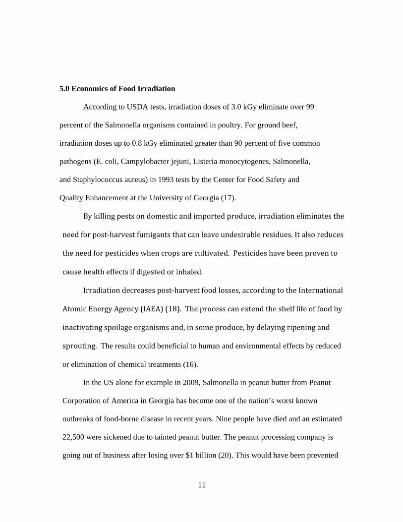
The general layout of the device can be found below in Figure 1. It is designed to
easily fit inside a standard semi tractor trailer truck’s container and is fully equipped with
the two linear accelerators (one to irradiate food from the top and the other to irradiate
food from the bottom), necessary cooling and vacuum equipment, conveyor system and
shielding. . The operator will place food on the conveyor; the conveyor will then move
17
the food through the two beams of electrons and out through the exit where the food will
be off loaded.
Figure 1: Top View of Mobile Food Irradiation Device

18
Figure 2: Side View of Mobile Food Irradiation Device inside Container
7.2 Source
The selected electron beam source is produced by Linac Technologies. This
company is located in France and is a major manufacturer of linear accelerators (11).
Linac Technologies has over 25 years in the irradiation industry and conducted research
in many areas including food irradiation, medical accelerator applications and research
applications. They produce a variety of accelerators from 10 keV to 10 MeV. Linac
Technologies provides all the support systems necessary to operate their accelerators as
well as detailed specifications for application and use (11). In this section of the report
the specifications and design of the accelerator will be detailed.
The accelerator produced by Linac Technologies selected in this mobile food
irradiation facility is the MeVAC. The MeVAC is a pulsed linear accelerator operating at
2998 MHz and producing electrons with energies below 10 MeV. The maximum power

19
achievable from this kind of accelerator is 3 kilowatts at a beam current of 0.3 mA (11).
The MeVAC comes standard with a 20 cm wide scan horn and a programmable
controller. The programmable controller can control the machine parameters as well as
communicate with the conveyor system, production line and ancillary equipment such as
the power supply, cooling system and the vacuum system. This allows for simple control
of all the systems involved with the irradiation facility in one single controller. The
MeVAC complies with FDA, AAMI and European standards so it could be operated
essentially anywhere in the world. The water cooling requirements include 2500 liters per
hour at a regulated temperature of about 25 degrees Celsius (11). This cooling system is
required to remove around 20 kilowatts of power in the form of heat from the accelerator.
The MeVAC requires 400 Volts 3-phase 50/60 Hz of electricity at 15 kilovolt amperes
current (11). The physical dimensions for this accelerator are 2 meters long and 0.5
meters in diameter with a weight of 200 kg. The high performance of this accelerator is
shown by the example of the ability to sterilize more than 1 cubic meter per hour for
products with a 0.15 density at 25 kGy (11). This is a very high rate considering the food
irradiation facility will only be irradiating food products to a maximum dose of about 5
kGy. The final specification for this accelerator is the price. The MeVAC linear
accelerator is around 3.25 million dollars. A computer generated image of the accelerator
is shown in Figure 3 below. With these specifications, the design of the accelerator for
the irradiator can be determined and outlined.

20
Figure 3: Computer model of MeVAC Accelerator
The design of the accelerator involves how it will be located and positioned in the
mobile irradiation system. The considerations involved in the design include how to
achieve maximum penetration, how to make it mobile and how to shield the sources. To
achieve maximum penetration, this irradiation facility will utilize two MeVAC
accelerators. One accelerator will be positioned above the product and one accelerator
will be positioned below the product. Both accelerators will direct the flow of electrons
toward the product being conveyed on a conveyor belt between the accelerators in the
irradiation facility. These accelerators will be offset so that they do not direct electrons
directly at each other. To meet transportation requirements, the beams will be turned 90

21
degrees so that the accelerators will fit above and below the conveyor and still be below
the required height for the department of transportation regulations (12). These 90 degree
bends will each have an extra 2 cm of lead around them to shield for the photons that are
produced while turning the beam. Each electron beam will have its own target once it
passes through the product being irradiated or the conveyor system when there is no food
on the belt. These targets are constructed of aluminum and cooled with the same system
used to cool the accelerator. This would help attenuate the electrons and reduce the
amount of shielding needed for safety for the operators and personnel around the
irradiator. The basic design seen from the side is shown below in Figure 4.
Figure 4: Irradiator Layout
The MeVAC linear electron accelerator specifications and layout described above
will allow for maximum penetration over a wide range of products. The ability for the
accelerator to produce a beam between 5 and 10 MeV allows for different dose rates and
amount of energy deposited in the product. This will allow for a wide range of
applications and this range can be extended by adjusting the speed of the conveyor belt.
MeVAC 1
MeVAC 2 20 cm Scan Horn
90° Bend
Conveyor System
Beam Target
Beam Target Lead for Bend

22
The slower the belt moves and the higher the energy of the beam, the higher the dose rate
to the product. The 20 cm scan horn width allows the conveyor system to be 20 cm in
width which keeps the facility compact but still efficient. This scan horn essentially
means that the product is passing thought a 20 cm wide plane of electrons as it moves
past each accelerator scan horn (11). Irradiating from both sides of the product allows for
a guaranteed consistent dose throughout the product (9). The mobile irradiation facility
with a MeVAC linear accelerator from Linac Technologies laid out in the design shown
above will allow a safe, cost effective and efficient operation.
7.3 Materials
The food will need to be moved through the radiation beam to receive dose since
the beam is stationary. A conveyor belt will be used to accomplish this task. Several
materials were considered for the conveyor, mainly steel, rubber, and plastic. Nylon and
cloth type materials were not considered due to the possibility of heavy products and a
need for durability as well as difficulty in cleaning.
Plastic and rubber materials (polymers) have similar characteristics in radiation
fields. Since polymers mare made of organic compounds with weak bonds between the
atoms in the structures, radiation can irreversibly break these bonds. When these bonds
are broken many changes can occur in polymers such as changes in chemical or physical
properties, appearance, and finally mechanical properties. To add to these effects, gas is
often created in the materials as well. Polymers can undergo two different types of
changes, either crosslinking or degradation can occur depending on the type of material.
Crosslinking is the formation of new bonds in the polymer structure. This does not allow

23
the material to hold the necessary three dimensional networks for the material to remain
as it is. Degradation refers to the permanent breaking of bonds in the material and can
lead to weakening of the material. Both of these processes will lead to the polymer
becoming brittle.
Rubber provides for a more flexible belt material than plastic. However, radiation
fields such as the electron field used for the irradiation of food will cause crosslinking in
most types of rubber and will undergo changes similar to those in the vulcanization (or
curing) process. This increases the hardness while decreases the flexibility of the rubber
and will eventually become brittle over prolonged periods of time. Figure 5 below shows
several different types of rubber and the dose that causes the rubber to be of limited use
or no use.
Figure 5: Radiation doses for multiple types of rubber.
24
From Figure 5 most types of rubbers are not useful over large doses and have significant
damage after 108 to 109 ergs/g. This is equal to about 1 to 10 Mrad, or 10 - 100 kGy.
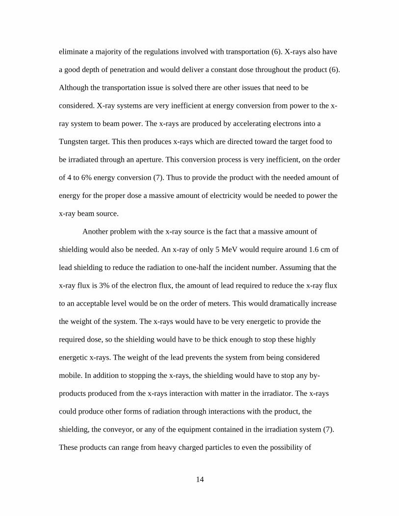
Plastic is more resistant to radiation compared to rubber. However, plastic will
still undergo degradation. Most plastics become useless at ranges of 10 – 100 Mrads, 100
– 1000 kGy, while some hard plastics are more radiation resistant. This is shown in
figure 6 below.
Figure 6: Radiation doses for plastics.
These are high radiation doses for polymers, however in high radiation fields it
will accumulate quickly. The electron beam used in this design will give a dose of 1
kGy/sec for and area of 600cm2. At this rate, an area of 600cm2, comparable to 1ft2, will
receive a maximum dose off 1 kGy in 1 second.
To overcome the radiation damage, steel mesh conveyor belts will be used. Steel
is much more resistant to radiation and electrons will cause little damage to steel.

25
However, electrons will cause atom displacements (dpa) in metals. As calculated in
section 8.5, the beam current used is 1.87 x10¹⁶ electrons/sec. As a conservative
approach, if each electron displaces one atom and Avogadro’s number counts for the
number of iron atoms in one mole of steel. There will be approximately 1x10⁻⁴ dpa/hr,
this leads to 2.6 x10⁵ hr for 30 dpa. 30 dpa is low enough to not cause serious damage to
steel which will allow the conveyor to provide flexibility and durability beyond any
polymer conveyor in a radiation field.
The problem with a steel conveyor is the creation of Bremsstrahlung radiation
from the interaction of electrons with the heavier elements in steel. These will not be
much of a problem since shielding will be initially modeled for Bremsstrahlung.
7.4 Shielding
Providing a food irradiation device which ensured the safety of workers and the
public was a major criterion in this design. To meet this objective while the device was
operational meant designing an effective shield which protected people around the truck
but which still allowed the intended purpose of fast, reliable food irradiation to take
place. First, an aluminum beam stop was employed due to being a lightweight, low Z
metal which decreased Bremsstrahlung radiation while stopping electrons. High density
polyethylene (HDPE) blocks were also utilized around the conveyor, linear accelerator
and vacuum/cooling systems for the same reasoning. In addition, lead shields of 2-3cm
were placed at the perimeter to attenuate any Bremsstrahlung radiation produced. In order
to accurately estimate the effectiveness of the design’s shielding given above design
26
components employed, MCNP simulations were utilized in our final calculations
(Appendix 11.2).
The premise of our shielding design was to stop the maximum 10MeV electrons
while producing as little Bremsstrahlung radiation as possible. This meant using lots of
low Z materials in the truck, which also helped in reducing the overall truck weight, but
still having enough lead to stop the photons which were produced during operation. The
design includes a 20x20x20cm cube of Aluminum (Z=13) as a beam stop located directly
across the conveyor from both linear accelerators and high density polyethylene blocks
machined to fit between and around components.
Polymers however are not entirely radiation resistant and will receive some
damage in radiation fields. Since having effective shielding is of concern, it was
necessary to determine what damage would occur to the HDPE and when.
There is often a threshold damage limit calculated for materials. This is where
radiation damage becomes noticeable, but doesn’t compromise important properties of
the material [2]. Damage can consist of broken bonds that can cause the material to
become brittle and decrease tensile strength.
The major polymer for shielding, polyethylene, has tensile strength reaching
threshold damage levels at 17 Mrad (100 kGy) and 25% damage at 7300 Mrad (73 MGy).
With an absorbed dose rate of 1 kGy hr-1, threshold damage occurs at 170 hours, and 25%
damage occurs at 73, 000 hours. Shear strength reaches 50 percent damage at 2900 kGy
(2,900 hours). Elongation, this refers to a decrease in elongation, of polyethylene, which
can reach up to 250 percent the original length, starts occurring at a threshold of 210 kGy
(210 hours). Elongation reaches 50 percent damage at 1600 kGy (1,600 hours) [2].
27
Given the material properties detailed above, polyethylene shielding will need to
be monitored to ensure safety is not compromised. The electron beam used has a dose
rate of 1000 Gy /sec, this is higher than the dose rate stated above for the damage levels.
The higher dose rate used in this design will cause threshold damage levels to be reached
at a quicker pace than stated. However, since polyethylene is not used as a beam stop
there will be a lower dose to the surrounding polyethylene shield and it is expected to last
longer than times given.
Lead shielding was designed to line the entire truck to stop any photons that were
produced due to Bremsstrahlung radiation from the electron beams. At the sides of the
truck the lead lining is 4cm thick while only 2cm thick on the top and bottom. In
addition, a wall of 3cm thick lead is also used to shield workers at their most probable
location where food is loaded and unloaded.
The MCNP5 simulation for shielding utilized the layout seen in Figures 1-2 and can
be found in Appendix 11.2. The results of the simulations show that no photons pass
through the area where the food would be loaded and unloaded and where any workers
present during operation would most likely be located. A photon flux of approximately
3.4E+7s-1 however is present at the opposite side of the truck directly in line with the two
accelerators where attenuation is at its lowest. Additional shielding as well as prohibiting
workers in this area during operation would be needed to ensure the lowest possible
exposure to those present.
28
7.5 Dose Calculations
Determining the dose that the product will receive by the irradiator is of extreme
importance. FDA regulations set the minimum and maximum dose that a particular food
can receive for a given purpose. This means that the center of the food must reach the
minimum dose requirement before the surface reaches the maximum allowable dose. In
order to obtain a reasonable estimate of the dose a product might receive with the given
design both analytical and computational methods were employed.
First, several assumptions had to be made before starting the calculations. It was
assumed that while the proposed linear accelerator can produce electrons in a variable
energy range, it would most likely be used at the maximum energy of 10MeV to
maximize the throughput of product thus increasing the affordability of use. Also, the
assumption was made that the majority of food products to be irradiated would consist
mostly of water, thus allowing the use of water as a reasonable substitute for dose
calculations.
An analytical method was first utilized to give a rough estimate of how much
surface dose could be obtained with the design’s purposed linear accelerators. Equation 1
(below) is the approximate dose rate from monoenergetic electrons on a uniform medium
(3). Here (dE/ρdx) is the collisional stopping power at depth x, which is equal to 2
MeV·cm2/g for 10MeV electrons (3). This equation only holds when the radiative
stopping power is not a large percentage of the total stopping power. Since the radiative
stopping power for 10MeV electrons is 8.4% of the total stopping power, this method is
only used as a rough estimate for the surface dose.

29
Next, the fluence rate ( ) for the linear accelerator was calculated using
Equations 2-3 (below). As was stated in the previous section, the maximum power output
of the MeVAC is 3kW. Using this, it was determined that the maximum flux rate from
the accelerator when it is producing 10MeV electrons is 1.87E+15 e-/s (Equation 3). In
order to determine dose however, the area which would be absorbing the energy had to be
calculated. To do this a hypothetical dose of 1kGy (the maximum allowed dose for
delayed ripening of fruits) was used to work backwards to determine the minimum
velocity of the 20cm wide conveyor (Equations 4-6). Thus it was determined that at the
maximum allowed energy of 10MeV and the maximum power output of 3kW, the
conveyor would need to move at a rate of 30cm/s.
(1)
(2)
(3)
(4)
(5)
(6)
30
This calculation can then be used to give a rough idea of throughput of the
product. For example, suppose a crop of strawberries was to be irradiated which had an
average diameter of 3cm. By applying an approximated spherical model, roughly 60
strawberries per second could be irradiated at the maximum energy and minimum speed.
Assuming the strawberries have a density of 1g/cc, this means that over 6kg/s or
21,600kg/hr of strawberries could be irradiated at the minimum speed.
More precise MCNP calculations were also completed. The simulation model
(found in Appendix 11.1) consisted of a 10MeV electron beam incident on a 12”x12”x6”
(30.48 x 30.48 x 15.24cm) slab of water surrounded by air. A mesh tally was used to
determine the dose in different thicknesses of water. The results of the simulation show
that 3.457E-13 Gy/electron was deposited in the first 2.54cm of water with a cross-
sectional area of 929cm2. Thus, for this same volume to receive a dose of 1kGy, it would
need to be irradiated by the linear accelerator (providing 1.87E+15 e-/s at maximum
power) for a period of 1.54 seconds. This corresponds to an area of 600cm2 receiving a
dose of 1kGy/s. Therefore, the conveyor would need to be traveling at a minimum
velocity of 30.03cm/s to stay below the maximum allowable dose of 1kGy – a figure
surprisingly close to the analytical calculation.
The MCNP simulation also provided dose estimates at greater depths into the
water/tissue simulate (see Figure 7 below). At 2.54 to 5.08cm, the dose is calculated at
2.661E-13 Gy/e-. If the minimum required dose were 0.3 kGy, as is the case for
controlling Trichinella spiralis in pork, then the conveyor would need to move at a
maximum speed of 77cm/s. Therefore, in such a case where the pork were no thicker than
10cm, the conveyor could move the food through at a speed anywhere between 30 and

31
77cm/s with the minimum dose reached at the center of the meat before the maximum
dose was received at the surface.
Figure 7: Dose as a function of depth
The dose was also simulated at greater thicknesses of water but starting at 5.08 to
7.62cm the dose dropped off significantly to 2.7E-15Gy/e-. This result however was
expected as the range of 10MeV electrons in water is only 4.88cm (3). Given the
previous scenario where a min dose of 0.3kGy and max dose of 1kGy were required, it
would be impossible for food of thicknesses above 10 cm to receive the minimum dose at
the center before the surface reached a maximum allowed dose. Given these calculations
and the known range of 10MeV electrons in water, this proposed food irradiation device
is only intended for a maximum food thickness of 8-9cm and through design will not
permit food thicknesses above 10cm since the open space for loading is only 10cm high.

32
7.6 Power Supply
The power supply for the food irradiation facility must provide enough electricity
for the linear accelerator and the support systems necessary for its operation. This
requires that the generator be able to produce a high voltage as required by the linear
accelerator but also a high current. The support systems will not require anywhere near as
much electricity as the linear accelerator (11). The support systems include the vacuum
system for the removal of air from the accelerator, the pump system for cooling the
accelerator and the electron targets, the conveyor belt for moving the product under the
beams and the detectors and safety systems in operation at all times to ensure the facility
meets all regulations. The current for the electricity also needs to be constant and
continuous (11). Not only does the power supplied have to be constant but the cost of
operation has to be low enough so that the food irradiation facility is cost effective. The
cost for operation for a generator is the gasoline or diesel fuel used to generate the
electricity, so the fuel consumption rate must be analyzed. Finally, the power supply must
be mobile. The electric generator must be able to travel with the food irradiation facility
and be plugged in to the facility and power the entire operation.
The generator found to fill this need is the Triton MMG230 – 204kW John Deere
sound attenuated generator set with trailer (19). The linear accelerator needs around 80
kW of continuous electricity for constant operation (11). Since there are two linear
accelerators in the mobile food irradiation facility this requirement becomes 160 kW of
electric power. With a 204kW generator this leaves 44kW for the support electronics.
This is more than enough power needed for the full facility to operate. The Triton
MMG230 is only 210 inches by 86 inches by 93 inches with the double axel trailer so it is

33
certainly mobile and could easily be pulled alongside the facility by a support truck
which would be needed to transport the workers (19). This generator produces 480 volts
at 303 amps (19). The generator has a 286 horsepower six cylinder diesel engine that
includes a 360 gallon fuel tank (19). This generator consumes fuel at 13.3 gallons an hour
at 1800 revolutions per minute which is the typical operating speed. This means that the
generator can be operated for around 27 hours on one tank of diesel fuel (19). This
consumption rate is cost effective and will allow for long operational periods. Finally the
price of the Triton MMG230 is $64,000. This is a small price to pay in comparison with
the massive costs of the linear accelerators. A picture of the MMG230 is shown below in
Figure 8.
Figure 8: Triton MMG230 204kW Diesel Generator
34
7.7 Safeguards
There are three categories that these fall in under; passive, administrative, and
active. The passive safeguards are as simple as the electron beam will not be able to be
turned on until all of the shielding is in place. The administrative safeguards are the
written rules of the site; such as warning signs that are placed in the areas of radiation,
and a red light on the outside of the trailer that turns on if the beam is turned on. The
active safety measures are the emergency shut off switches that are around the trailer.
According to IAEA document Safety Series No. 107,
“Means shall be provided such that the personnel access door to the radiation
room is closed and secured before the irradiation process can begin. The door
interlocks shall be integrated with the master control system such that violation of
the interlock system or use of the door will cause the radiation to be automatically
terminated. Any failure of the control system shall generate visible and audible
alarm signals. Opening the access door shall also disable the source hoist control
circuit and cut off the motive power to the source hoist operating mechanism in
the case of gamma facilities, or switch off the high voltage supply for electron
beam facilities. The disabling of the source hoist control circuit and the cut-off of
the motive power to the source hoist operating mechanism must be accomplished
by independent actions.” (21)
For the design, the shielding is permanent; however, there are small sections of
shielding which is removable. The facility has a system which interlocks access panels
and a personal access door to repair the electron beams and the conveyor belt as well as
clean the interior of the trailer. There will be emergency shutoff switches inside the
35
trailer placed in areas of maintenance and loading to ensure that no personnel will be
inside the facility during times of operation. Another emergency shut off switch is on the
outside of the trailer next to the personnel access door and on the exterior of the diesel
generator. All of the emergency shut offs will be on the same circuit. Also, there is a
circuit along the shell of the trailer that goes through the parts of the trailer which provide
access to the interior of the facility. This is similar in principle to the door and window
alarms that are used for home security. Both of these circuits automatically shut off the
electron beam if the circuit is broken. On another circuit will be a system which detects
if the conveyor belt is stopped for any reason. This is in the event that the conveyor
malfunctions or stalls preventing the product and conveyor from moving from radiation
field. When any one of the systems is compromised, they will automatically disrupt
current flow and shut off the electron beam. The systems cannot be turned back on until
all of the separate systems are reset and confirmed as being safe and ready for use.
The workers will have training courses on the safe uses, as well as informed of the
consequences for the unsafe usage of the machinery. Also, due to radiation from
Bremsstrahlung no one will be allowed in a 10 foot radius of the facility during operation.
The area will be cordoned off with removable barriers and security personnel will be
employed to ensure trespassing does not occur. The only exemption for this rule will be
those who are loading and unloading the foods on and off the conveyor belt. The loading
and unloading access is not big enough for access to the interior of the facility so
radiation is not a concern.
Inside the trailer, there are also a couple of built in safety systems. These systems
will monitor the electron beams to make sure everything is operating within the
36
parameters. This will also be a way to log any failures and plan future repair schedules.
The other system will have test points for machine diagnostics without resorting to
disabling the electron beam or bypassing the interlocks (21). There will be a closed
circuit television to monitor this.
8.0 Future Work
The design and layout for this facility needs more work from different
engineering specialties. Mechanical, civil, industrial, electrical and systems engineers are
needed to enhance the design and functionality of the facility. There are several areas that
require the contribution of other engineering disciplines for the facility to be ready for
production.
One area that needs more work is the design of the facility. How the food is
loaded and unloaded as well as how the food moves through the beam. The basic layout
was examined and a reasonable system was determined. However an engineer with
experience in conveyor systems and loading and unloading systems could make the
system more efficient and more reliable. Higher efficiency means lower cost and more
throughput of the product. The more reliable the facility is the more food can be
processed and the less down time the facility has. This will allow for more profit from the
facility since less money will need to be spent to fix the system.
Another area that needs more development is the maintenance of the facility.
Currently the maintenance is not addressed in depth. Additional work needs to be done to
make the conveyor, electron beams, and support systems more easily serviceable. The
more easily serviceable the facility is the quicker it can be brought back to working

37
condition if something does break. This allows less down time and more time to be
running product through the facility for irradiation. Some designs have been discussed
that should be looked into further with more time. One idea suggested was to make the
whole system able to be raised with hydraulic rams from the base. This would allow a
worker to crawl under the facility and service the components from below and inside the
system. Another option was to make the shielding removable, thus allowing access to the
components from the sides and top of the facility. Both of these are viable options and
need more research and future work.
Future work is also needed on how all of the systems in the facility are integrated
together. Essentially this means how the electron beam is coupled to the conveyor belt
and all the other support systems contained in the irradiation facility. There are many
variables that can be adjusted to provide the product with the appropriate amount of
irradiation. The conveyor speed can be adjusted, the distance to the product can be
adjusted, the energy and intensity of the beam can be adjusted, the thickness of the
product may vary and all need of the various factors need to be considering for
maintaining minimum and maximum dose rates to the product. All of these factors can be
integrated into one primary control system that is used to maintain the correct amount of
radiation for the desired output product. This would allow an operator to input the
variables and receive required system settings without calculations. This would eliminate
the element of human error and possibly make the facility safer. This is an area that an
electrical engineer would be needed as well as a systems engineer or someone with
system knowledge.

38
There are many areas where future work needs to be performed before the
irradiation facility goes to production. Some of these areas are listed in this report; others
are not included but would be discovered upon more in depth research into this challenge.
All of these areas need to be developed fully before a prototype is produced. The work
for these sections could not be included in this report due to time constraints and lack of
information and knowledge. However, given more time and a more diverse group of
engineers these areas of future work could be developed and moved to production.
9.0 Conclusion
This paper details the design of a mobile irradiation facility. The facility will use
electron beams produced by two linear accelerators to irradiate products passing between
them. The linear accelerators will produce electrons from 5 to 10 MeV with a maximum
power of 3 kW. The electron beam produced by the linear accelerator was selected
mainly due to the fact that less shielding was required than for the Cobalt 60 source or for
the x-ray source. The food products will pass between the linear accelerators via a
conveyor belt made of steel mesh. Steel mesh was selected for the conveyor belt since it
is highly radiation resistant. The operators and personnel around the irradiator will be
protected from the radiation by high density polyethylene and lead shielding. High
density polyethylene was used for the primary shielding because it will effectively stop
electrons while producing a small amount of Bremsstrahlung radiation. Lead shielding
was also used to strop the Bremsstrahlung produced in the polyethylene and other
materials contained in the facility. The facility will be powered by a generator contained
on a trailer. The generator was selected for its uniform power production and ease of use.

39
Safety systems were designed to ensure the safe operation and maintenance of the
system. The total cost of the system is estimated to be between 7 and 8 million dollars.
This cost is reasonable due to the need for a mobile facility. A mobile irradiation facility
could travel to a manufacturer where an outbreak of infected or diseased product has been
detected and ensure that the future products produced do not endanger the health of the
consumers. The ability to rapidly respond to special situations makes this mobile
irradiation facility a necessity.
40
10.0 References
1. Title 21 of the code of Federal Regulations, Chapter 179 (21CFR179);
http://www.cfsan.fda.gov/~dms/apa-docs.html
2. Effects of Radiation on Materials and Components; Kircher, John F.; Bowman,
Richard E.; Reinhold Publishing Corporation, New York. 1964.
3. Atoms, Radiation, and Radiation Protection; Turner, James E; Wiley-VCH,
Weinheim, 2007.
4. United States Environmental Protection Agency, Radiation Protection, Cobalt 60; http://www.epa.gov/rpdweb00/radionuclides/cobalt.html
5. United States Nuclear Regulatory Commission, Fact Sheet on commercial
Irradiators; http://www.nrc.gov/reading-rm/doc-collections/fact-sheets/commercial-irradiators.html
6. US Food and Drug Administration Radiological Health Program, Cabinet X-Ray
Systems; http://www.fda.gov/cdrh/radhealth/products/cabinetxray.html 7. INSPX, X-Rays and Radiation; http://www.inspx.com/xray.html
8. Organic Consumers Association, Fact Sheet: Irradiation Using Electron Beams;
http://www.organicconsumers.org/Irrad/EBeamInfo.cfm
9. The Journals of the Institute of Validation Technology, Basic Operating Principals and Validation of Electron Beam Irradiation Systems; http://www.gxpandjvt.com/ivtnews/templates/IVTNews.aspx?articleid=1440&zoneid=18
10. The National Center for Electron Beam Research;
http://www.tamu.edu/ebeam/faq.html 11. Linac Technologies; http://www.linactechnologies.com/linac_site.html
12. US Department of Transportation, Dockets and Regulations;
http://www.dot.gov/regulations.html
13. Private Conversation: Mount, John; Department of Food Science and Technology, University of Tennessee; Science and Technology of Irradiation. 2009.

41
14. Private Conversation: Hughes, Patrick; Sterigenics International; March 2009
15. FMI (Food Marketing Institute); http://www.fmi.org/media/bg/Irradiation.pdf
16. IAEA Bulletin Vol.20, No.1;
http://www.iaea.org/Publications/Magazines/Bulletin/Bull201/20105706466.pdf
17. FMI (Food Marketing Institute); http://www.fmi.org/media/bg/Irradiation.pdf
18. “Dangers of Irradiation Facilities,” Organic Consumers Association, March 14, 2001, http://www.organicconsumers.org/Irrad/dangers.cfm
19. Triton Power; www.tritonpower.com/generators
20. Centers for Disease Control and Prevention (CDC) ; Multistate Outbreak of
Salmonella Infections Associated with Peanut Butter and Peanut Butter-Containing Products – United States, 2008-2009 ; http://www.cdc.gov/mmwr/preview/mmwrhtml/mm58e0129a1.htm
21. International Atomic Energy Agency. "Radiation safety of Gamma and Electron
Irradiation Facilities."Safety Series . No 107. 1992.
42
11.0 Appendix
11.1 MCNP5 Model for Dose Calculations
food irradiator: 10 MeV e- on target, lead shielded, water target c Cell Descriptions c W converter c 1 1 -19.3 2 -3 -1 imp:p,e=1 c air between W and Pb 2 4 -1.20479e-3 4 -5 6 -7 8 -9 imp:p,e=1 c (-2:3:1) imp:p,e=1 c Pb shielding 3 2 -11.344 10 -11 12 -13 14 -9 (-4:5:-6:7:-8:9) imp:p,e=1 c water being irradiated 4 3 -0.9982 15 -16 17 -18 19 -191 imp:p,e=1 41 3 -0.9982 15 -16 17 -18 191 -192 imp:p,e=1 42 3 -0.9982 15 -16 17 -18 192 -193 imp:p,e=1 43 3 -0.9982 15 -16 17 -18 193 -194 imp:p,e=1 44 3 -0.9982 15 -16 17 -18 194 -195 imp:p,e=1 45 3 -0.9982 15 -16 17 -18 195 -20 imp:p,e=1 c air outside pb and water 5 4 -1.20479e-3 10 -11 12 -21 22 -20 (-10:11:-12:13:-14:9) (-15:16:-17:18:-19:20) imp:p,e=1 6 0 (-10:11:-12:21:-22:20) imp:p,e=0 c Surface Descriptions c converter surfaces 1 cz 10 2 pz 0 3 pz .2 c inside air surfaces 4 px -30.48 5 px 30.48 6 py -30.48 7 py 30.48 8 pz -30.48 9 pz 30.48 c lead shield surfaces 10 px -40.64 11 px 40.64 12 py -40.64 13 py 40.64 14 pz -40.64 c block of water surfaces 15 px -15.24 16 px 15.24 17 py -15.24 18 py 15.24 19 pz 60.96 191 pz 63.5 192 pz 66.04 193 pz 68.58 194 pz 71.12 195 pz 73.66 20 pz 76.2 c boundary of problem - add 1 cm for mesh tallies 21 py 41.64 22 pz -41.64 mode p e c c Variance reduction c c bbrem 1 1 46i 100 1 c c Source

43
c c 10 MeV electrons into W sdef pos=0.0 0.0 0.0 $ spatial erg=10 $ energy par=e $ source type vec=0 0 1 dir=d1 $ direction si1 -1 0 0.970142500 1 sp1 0 0 0 1 c c Tallies c fc4 Photon dose rate tally behind electron accelerator - cSv/hr (rem/hr) fmesh4:p geom=xyz origin=-40.64 -40.64 -41.64 imesh 40.64 iints 30 jmesh 40.64 jints 30 kmesh -40.64 kints 1 out=ij de4 log 0.01 0.03 0.05 0.07 0.1 0.15 0.2 0.25 0.3 0.35 0.4 0.45 0.5 0.55 0.6 0.65 0.7 0.8 1 1.4 1.8 2.2 2.6 2.8 3.25 3.75 4.25 4.75 5 5.25 5.75 6.25 6.75 7.5 9 11 13 15 df4 log 3.96E-06 5.82E-07 2.90E-07 2.58E-07 2.83E-07 3.79E-07 5.01E-07 6.31E-07 7.59E-07 8.78E-07 9.85E-07 1.08E-06 1.17E-06 1.27E-06 1.36E-06 1.44E-06 1.52E-06 1.68E-06 1.98E-06 2.51E-06 2.99E-06 3.42E-06 3.82E-06 4.01E-06 4.41E-06 4.83E-06 5.23E-06 5.60E-06 5.80E-06 6.01E-06 6.37E-06 6.74E-06 7.11E-06 7.66E-06 8.77E-06 1.03E-05 1.18E-05 1.33E-05 c fc14 Photon dose rate tally above electron accelerator - cSv/hr (rem/hr) fmesh14:p geom=xyz origin=-40.64 40.64 -40.64 imesh 40.64 iints 30 jmesh 41.64 jints 1 kmesh 40.64 kints 30 out=ik de14 log 0.01 0.03 0.05 0.07 0.1 0.15 0.2 0.25 0.3 0.35 0.4 0.45 0.5 0.55 0.6 0.65 0.7 0.8 1 1.4 1.8 2.2 2.6 2.8 3.25 3.75 4.25 4.75 5 5.25 5.75 6.25 6.75 7.5 9 11 13 15 df14 log 3.96E-06 5.82E-07 2.90E-07 2.58E-07 2.83E-07 3.79E-07 5.01E-07 6.31E-07 7.59E-07 8.78E-07 9.85E-07 1.08E-06 1.17E-06 1.27E-06 1.36E-06 1.44E-06 1.52E-06 1.68E-06 1.98E-06 2.51E-06 2.99E-06 3.42E-06 3.82E-06 4.01E-06 4.41E-06 4.83E-06 5.23E-06 5.60E-06 5.80E-06 6.01E-06 6.37E-06 6.74E-06 7.11E-06 7.66E-06 8.77E-06 1.03E-05 1.18E-05 1.33E-05 c fc24 Photon flux tally at the exit of the Pb shield fmesh24:p geom=xyz origin=-30.48 -30.48 30.48 imesh 30.48 iints 24 jmesh 30.48 jints 24 kmesh 31.48 kints 1 out=ij c fc34 Photon flux in irradiated water fmesh34:p geom=xyz origin=-15.24 -15.24 60.96 imesh 15.24 iints 12 jmesh 15.24 jints 12 kmesh 76.2 kints 6 out=ij c fc44 Electron flux in irradiated water fmesh44:e geom=xyz origin=-15.24 -15.24 60.96 imesh 15.24 iints 12 jmesh 15.24 jints 12 kmesh 76.2 kints 6 out=ij c fc8 Exact absorbed dose in irradiated water - Gy *f8:p,e 4 41 42 43 44 45 t e8 1e30 em8 6.80188641e-14 c c Materials c c tungsten 19.3 g/cc m1 74182 0.26420 74183 0.14280 74184 0.30700 74186 0.28600 nlib=70c plib=04p pnlib=70u elib=03e c
44
c lead 11.344 g/cc m2 82204 0.0140 82206 0.2410 82207 0.2210 82208 0.5240 nlib=70c plib=04p pnlib=70u elib=03e c c water 0.9982 g/cc m3 1001 1.9997 1002 0.0003 8016 0.9976 8017 0.0024 nlib=70c plib=04p pnlib=70u elib=03e c c dry air at sea level 1.20479e-3 g/cc m4 6000 -0.000127 7014 -0.76508 8016 -0.234793 nlib=70c plib=04p pnlib=70u elib=03e c c Physics options c phys:n phys:p 4j 1 phys:e c c Cutoffs cut:n cut:p j 0.001 $ default energy cut off, 1 keV cut:e j 0.001 $ default energy cut off, 1 keV c elpt $ cell by cell energy cut off, could be useful nps 3900 c ctme 10 c c Peripheral print rand gen=2 stride=305835 prdmp 3j 2 c
11.2 MCNP5 Model for Shielding Calculations
c c Simple Geometry Setup for Mobile Food Irradiator c Created for NE472 Senior Design Project 3/25/09 c ********************************************************************** c Cell Cards c ***************************************************************************** c c 6 206 17 -11.34 (-6 5 1 2) IMP:P,E = 1 c c 5 205 3 -0.95 (-5 1 2 3 4 7 8 9 10 11 12 13 14 15 16 17 18 19 20 21 22 24 25) IMP:P,E = 1 c c 3 203 10 -3.054 (-3) IMP:P,E = 1 c c 4 204 10 -3.054 (-4) IMP:P,E = 1 c c 8 208 10 -3.054 (-8) IMP:P,E = 1 c c 9 209 10 -3.054 (-9) IMP:P,E = 1

45
c c 17 217 22 -7.86 (-17) IMP:P,E = 1 c c 18 218 22 -7.86 (-18) IMP:P,E= 1 c c 19 219 22 -7.86 (-19) IMP:P,E = 1 c c 20 220 22 -7.86 (-20) IMP:P,E = 1 c c 21 221 22 -7.86 (-21) IMP:P,E = 1 c c 22 222 22 -7.86 (-22) IMP:P,E = 1 c c 7 207 17 -11.34 (-7) IMP:P,E = 1 c c 2 202 7 -0.001205 (-2) IMP:P,E = 1 c c 1 201 7 -0.001205 (-1) IMP:P,E = 1 c c 10 210 7 -0.001205 (-10) IMP:P,E = 1 c c 11 211 7 -0.001205 (-11) IMP:P,E = 1 c c 12 212 7 -0.001205 (-12) IMP:P,E = 1 c c 13 213 7 -0.001205 (-13) IMP:P,E = 1 c c 14 214 7 -0.001205 (-14 1 2) IMP:P,E = 1 c c 15 215 7 -0.001205 (-15) IMP:P,E = 1 c c 16 216 7 -0.001205 (-16) IMP:P,E = 1 c c 24 224 4 -2.7 (-24) IMP:P,E = 1 c c 25 225 4 -2.7 (-25) IMP:P,E = 1 c c 26 226 7 -0.001205 (-26) IMP:P,E = 1 c c Explicit Blackhole/Universe c 00023 0 +1 IMP:N,P,E = 0 c c 98 7 -0.001205 (-23 6 1 2 26) IMP:P,E = 1 98 0 (-23 6 1 2 26) IMP:P,E = 0 99 0 (23) IMP:P,E = 0 c ********************************************************************** c SurfaceCards c ********************************************************************** c c 1

46
1 BOX 550.00 200.00 87.00 50.00 0.00 0.00 0.00 50.00 0.00 0.00 0.00 20.00 c c 2 2 BOX 50.00 200.00 87.00 50.00 0.00 0.00 0.00 50.00 0.00 0.00 0.00 20.00 c c 3 3 Box 50.00 40.00 25.00 200.00 0.00 0.00 0.00 50.00 0.00 0.00 0.00 50.00 c c 4 4 Box 230.0 95.00 100.00 200.00 0.00 0.00 0.00 50.00 0.00 0.00 0.00 50.00 c c 5 5 BOX -18.00 -18.00 2.00 864.00 0.00 0.00 0.00 255.00 0.00 0.00 0.00 300.00 c c 6 6 BOX -22.00 -22.00 0.00 872.00 0.00 0.00 0.00 261.00 0.00 0.00 0.00 304.00 c c 7 7 BOX 45.00 190.00 2.00 580.00 0.00 0.00 0.00 3.00 0.00 0.00 0.00 150.00 c c 8 8 BOX 50.00 92.00 50.00 170.00 0.00 0.00 0.00 80.00 0.00 0.00 0.00 50.00 c c 9 9 BOX 260.00 12.00 50.00 170.00 0.00 0.00 0.00 80.00 0.00 0.00 0.00 50.00 c c 10 10 BOX 230.00 12.00 86.00 20.00 0.00 0.00 0.00 163.00 0.00 0.00 0.00 10.00 c c 11 11 BOX 230.00 12.00 75.00 20.00 0.00 0.00 0.00 163.00 0.00 0.00 0.00 10.50 c c 12 12 BOX 230.00 12.00 87.00 0.00 20.00 0.00 -210.00 0.00 0.00 0.00 0.00 10.00 c c 13 13 BOX 20.00 32.00 87.00 20.00 0.00 0.00 0.00 163.00 0.00 0.00 0.00 10.00 c c 14 14 BOX 650.00 195.00 87.00 0.00 20.00 0.00 -630.00 0.00 0.00 0.00 0.00 10.00 c c 15 15 BOX 630.00 155.00 87.00 20.00 0.00 0.00 0.00 40.00 0.00 0.00 0.00 10.00 c c 16 16 BOX 630.00 155.00 87.00 0.00 20.00 0.00 -380.00 0.00 0.00 0.00 0.00 10.00 c c 17 17 BOX 230.00 12.00 85.50 20.00 0.00 0.00 0.00 163.00 0.00 0.00 0.00 0.50 c c 18 18 BOX 230.00 12.00 85.00 0.00 20.00 0.00 -210.00 0.00 0.00 0.00 0.00 2.00 c c 19

47
19 BOX 20.00 32.00 85.00 20.00 0.00 0.00 0.00 163.00 0.00 0.00 0.00 2.00 c c 20 20 BOX 650.00 195.00 85.00 0.00 20.00 0.00 -630.00 0.00 0.00 0.00 0.00 2.00 c c 21 21 BOX 630.00 155.00 85.00 20.00 0.00 0.00 0.00 40.00 0.00 0.00 0.00 2.00 c c 22 22 BOX 630.00 155.00 85.00 0.00 20.00 0.00 -380.00 0.00 0.00 0.00 0.00 2.00 c c 23 23 BOX -1000 -1000 -1000 2000 0 0 0 2000 0 0 0 2000 c c 24 24 Box 230.00 55.00 96.00 20.00 0.00 0.00 0.00 20.00 0.00 0.00 0.00 20.00 c c 25 25 Box 230.00 110.00 55.00 20.00 0.00 0.00 0.00 20.00 0.00 0.00 0.00 20.00 c c 26 26 Box 230.00 -40.00 76.00 20.00 0.00 0.00 0.00 20.00 0.00 0.00 0.00 20.00 c c Material Cards c Mode P E c m3 1001 -0.143711 $ HDPE, rho = 0.95 6000 -0.856289 c m10 1001 -3.386 $ Electronics Components, rho=3.054 g/cc 6000 -7.175 7014 -0.015 8016 -38.870 11023 -0.086 12000 -0.972 13027 -16.95 14000 -8.948 15031 -0.006 16000 -0.004 20000 -4.217 24000 -2.438 25055 -0.482 26000 -10.753 28000 -1.022 29000 -1.547 30000 -0.669 56138 -2.458 82000 -0.001 c m22 6000 -0.0015 $ C Steel conveyor, rho=7.86 g/cc 24000 -0.13 $ Cr 25055 -0.0125 $ Mn 14000 -0.01 $ Si 15031 -0.0006 $ P 16000 -0.0015 $ S 26000 -0.8439 $ Fe c m17 82000 -1 $ Lead, rho=11.34 c m7 6000 -0.000124 $ C Air, rho=0.001205 g/cc 7014 -0.755267 $ N 8016 -0.231781 $ O 18000 -0.012827 $ Ar c

48
m4 13027 -1 $ Al, rho=2.7g/cc c c c bbrem 1 1 46i 100 1 c c c sdef pos=240.0 120.0 96.00 $ spatial c erg=10 $ energy c par=e $ source type c vec=0 0 -1 dir=d1 $ direction c sur=10.5 c si1 -1 0.970142500 1 c sp1 0 0 1 c sdef pos=240.0 65.0 75.00 $ spatial erg=10 $ energy par=e $ source type vec=0 0 1 dir=d1 $ direction sur=3.5 si1 -1 0.970142500 1 sp1 0 0 1 c c c F4:P 201 202 226 T E4: 0.002 100i 10 c c F2:P 1.3 26.3 c E2: 0.002 100i 10 c phys:n phys:p 4j 1 phys:e c c cut:n cut:p j 0.001 cut:e j 0.001 c c ctme 10 c nps 500000 c c *F8 c print rand gen=2 stride=305835 prdmp 3j 2 c c F4 c c
Related Documents