DOI: 10.1002/adem.201700319 A Microvascular System for the Autonomous Regeneration of Large Scale Damage in Polymeric Coatings** By Ryan C. R. Gergely, Michael N. Rossol, Sharon Tsubaki, Jonathan Wang, Nancy R. Sottos and Scott R. White* Self-healing polymers are capable of self-repair either in response to the damage or through external stimuli, but are limited in their ability to autonomously control the volume of healing agents released, in the length scale of damage they address, and in their ability to respond to multiple damage events. Here, the authors report a novel design for healing agent storage and release for vascular coating systems that allows for complete regeneration of a coating with precise and autonomous control of coating thickness. A variety of healing agent formulations that cure under ambient sunlight are explored and their cure profiles and mechanical properties are reported. In the proposed vascular coating system, the stored healing agent remains stable within the network until large-scale damage (e.g., abrasion) completely removes the protective coating. A precise volume within the network is then released, and cures when exposed to simulated sunlight to reform the protective coating. This coating system facilitates consistent coating thickness and hardness for several cycles of coating removal and regeneration. 1. Introduction The burgeoning field of self-healing materials offers the potential for synthetic materials that have biological-like responsiveness to repair themselves when damaged. The potential advantages of this approach in materials design is improved service lifetime and safety, as well as reduced overdesign typical in engineering structures. [1–3] Historically, research in self-healing polymers and composites has targeted damage due to scratches, fracture, delamination, and puncture. [4–9] No matter the type of healing system invoked (capsule-based, vascular, or intrinsic), nearly all are relegated to small scale damage modes. Protective coatings shield the underlying substrate from harsh environmental conditions. Regular inspection and repair intervals are required to maintain protection – self-healing coatings aim to reduce or eliminate this required maintenance. Previous demonstrations of self-healing polymeric coatings have almost exclusively focused on cracks or scratch damage. In both microcapsule and microvascular systems, reactive fluids (healing agents) are released in response to damage. [7,8] When the scale of damage is small, healing agents can be drawn into the crack via capillary forces. Intrinsic systems are inherently reversible and reform bonds when there is intimate contact of the damage surfaces. [10,11] However, if the damage is sufficiently large, transport of the healing agent by capillary forces is inhibited, and reversible bonding is not possible due to the separation between damage surfaces. In addition, capsule based systems are limited both in their payload (total volume of healing agent) and they only allow for a single repair event. [7] In contrast, microvascular systems can deliver a potentially [*] Prof. S. R. White Department of Aerospace Engineering, Beckman Institute for Advanced Science and Technology, University of Illinois at Urbana-Champaign, Urbana, IL, 61801, USA E-mail: [email protected] Dr. R. C. R. Gergely, S. Tsubaki Department of Mechanical Science and Engineering, Beckman Institute for Advanced Science and Technology, University of Illinois at Urbana-Champaign, Urbana, IL, 61801, USA Dr. M. N. Rossol, J. Wang, Prof. N. R. Sottos Department of Materials Science and Engineering, Beckman Institute for Advanced Science and Technology, University of Illinois at Urbana-Champaign, Urbana, IL, 61801, USA [**] This work has been financially supported by the Air Force Office of Scientific Research (AFOSR, grant number, FA9550-16-1- 0017). J. W. and S. T. were partially funded by the Illinois Space Grant Consortium Undergraduate Research Opportunity Program (UROP). We extend our gratitude to J. S. Moore for advice, insightful discussions, and expert opinion on the development of regenerative polymeric systems. We also thank C. B. Montgomery for his assistance with microscope imaging. (Supporting Information is available online from Wiley Online Library or from the author). DOI: 10.1002/adem.201700319 © 2017 WILEY-VCH Verlag GmbH & Co. KGaA, Weinheim wileyonlinelibrary.com (1 of 10) 1700319 ADVANCED ENGINEERING MATERIALS 2017, FULL PAPER

Welcome message from author
This document is posted to help you gain knowledge. Please leave a comment to let me know what you think about it! Share it to your friends and learn new things together.
Transcript
FU
DOI: 10.1002/adem.201700319LLPAPER
A Microvascular System for the Autonomous Regenerationof Large Scale Damage in Polymeric Coatings**
By Ryan C. R. Gergely, Michael N. Rossol, Sharon Tsubaki, Jonathan Wang, Nancy R. Sottosand Scott R. White*
Self-healing polymers are capable of self-repair either in response to the damage or through externalstimuli, but are limited in their ability to autonomously control the volume of healing agents released,in the length scale of damage they address, and in their ability to respond to multiple damage events.Here, the authors report a novel design for healing agent storage and release for vascular coatingsystems that allows for complete regeneration of a coating with precise and autonomous control ofcoating thickness. A variety of healing agent formulations that cure under ambient sunlight areexplored and their cure profiles and mechanical properties are reported. In the proposed vascularcoating system, the stored healing agent remains stable within the network until large-scale damage(e.g., abrasion) completely removes the protective coating. A precise volume within the network is thenreleased, and cures when exposed to simulated sunlight to reform the protective coating. This coatingsystem facilitates consistent coating thickness and hardness for several cycles of coating removal andregeneration.
1. Introduction responsiveness to repair themselves when damaged. The
The burgeoning field of self-healing materials offers thepotential for synthetic materials that have biological-like
[*] Prof. S. R. WhiteDepartment of Aerospace Engineering, Beckman Institute forAdvanced Science and Technology, University of Illinois atUrbana-Champaign, Urbana, IL, 61801, USAE-mail: [email protected]. R. C. R. Gergely, S. TsubakiDepartment of Mechanical Science and Engineering, BeckmanInstitute for Advanced Science and Technology, University ofIllinois at Urbana-Champaign, Urbana, IL, 61801, USADr. M. N. Rossol, J. Wang, Prof. N. R. SottosDepartment of Materials Science and Engineering, BeckmanInstitute for Advanced Science and Technology, University ofIllinois at Urbana-Champaign, Urbana, IL, 61801, USA
[**] This work has been financially supported by the Air Force Officeof Scientific Research (AFOSR, grant number, FA9550-16-1-0017). J. W. and S. T. were partially funded by the Illinois SpaceGrant Consortium Undergraduate Research OpportunityProgram (UROP). We extend our gratitude to J. S. Moorefor advice, insightful discussions, and expert opinion on thedevelopment of regenerative polymeric systems. We also thankC. B. Montgomery for his assistance with microscope imaging.(Supporting Information is available online from Wiley OnlineLibrary or from the author).
DOI: 10.1002/adem.201700319 © 2017 WILEY-VCH Verlag GmbH &ADVANCED ENGINEERING MATERIALS 2017,
potential advantages of this approach in materials design isimproved service lifetime and safety, as well as reducedoverdesign typical in engineering structures.[1–3] Historically,research in self-healing polymers and composites has targeteddamage due to scratches, fracture, delamination, andpuncture.[4–9] No matter the type of healing system invoked(capsule-based, vascular, or intrinsic), nearly all are relegatedto small scale damage modes.
Protective coatings shield the underlying substrate fromharsh environmental conditions. Regular inspection and repairintervals are required to maintain protection – self-healingcoatings aim to reduce or eliminate this required maintenance.Previous demonstrations of self-healing polymeric coatingshavealmost exclusively focusedoncracksor scratchdamage. Inboth microcapsule and microvascular systems, reactive fluids(healing agents) are released in response to damage.[7,8] Whenthe scale of damage is small, healing agents can be drawn intothe crack via capillary forces. Intrinsic systems are inherentlyreversible and reform bonds when there is intimate contact ofthedamagesurfaces.[10,11]However, if thedamage issufficientlylarge, transport of the healing agent by capillary forces isinhibited, and reversible bonding is not possible due to theseparation between damage surfaces. In addition, capsulebased systems are limitedboth in their payload (total volumeofhealing agent) and theyonly allowfor a single repair event.[7] Incontrast, microvascular systems can deliver a potentially
Co. KGaA, Weinheim wileyonlinelibrary.com (1 of 10) 1700319

Fig. 1. Coating regeneration cycle and design. (1) Coating damage and removal triggersthe release of liquid healing agent stored in the underlying vasculature. (2) Embeddedaccumulator releases a prescribed volume of healing agent to the surface. (3) A one-parthealing agent reforms the protective coating when exposed to simulated sunlight. Thesurface valve protects the unreacted healing agent stored within the vascular substrateby blocking UV penetration.
R. C. R. Gergely et al./Autonomous Regeneration of Polymeric Coatings. . .
FULLPAPER
inexhaustible supplyofhealingagentsandtheyenablemultiplerepair events.[8,9,12] Introducing a pressurized microvascularsystem can overcome the limitations of capillary forces, as wellas reduce the density of microvascular channels necessary torecover a given damage size.[4,5]
Recently,Gergelyetal.utilizedapressurizeddeliverysystemwith amicrovascular healing approach to regenerate polymericcoatings in response to large scale abrasive damage.[12] Avalvethat blocked UV penetration into a vascularized substrate bothprotected the stored healing agent from premature curing andisolated the abrasive damage from the vascular network. Thissystemutilized a one-part sunlight curable epoxyhealing agentto eliminate the necessity for in situ mixing prevalent in self-healingsystems.[6,9]Despite its success,onekey limitationof thecoating system was the requirement for external control toterminate the flow of healing agent during the regenerationevent in order to avoid excessive bleed out.
A significat body of research has developed around light-healing systems that use a photochemical approach to inducerepair.[13–19] Light-healing systems can potentially harnessenergy from sunlight to enable self-healing, thus requiring nohuman intervention. Various types of damage have beentargetted by light-healable systems from scratches in coat-ings[13,14] to partial or complete fracture.[15–19] In contrast toexisting light-healable coatings, this work targets completeabrasive removal of the coating that exposes the substrate, anduses commercially availible chemistries to formulate sunlighthealing agents for coatings.
In this paper, we report on a novel storage and releasemechanism for autonomous regeneration of polymer coatings.Our design relies on a pressure-activated membrane element(an “accumulator”) that stores a prescribed volume of healingagent. Integration of the accumulator, as a localized reservoir ina microvascular network, eliminates the need for externalcontrol of healing agent delivery. We also consider threeimportant factors in the design of a regenerative system: therelevant timescales of the regeneration cycle, modulation ofthese timescales, and tuning of the healing agent volumereleased. New sunlight curable healing agents are explored forboth modulation of curing kinetics and mechanical perfor-mance. Factors affecting the volume of healing agents releasedand the timescale for their delivery are studied. The healingagent payload volume is calibrated by both experimentalmeasurement and an analytical model. Multiple regenerationcycles of protective polymer coating with controlled thicknessare demonstrated using a sunlight curable healing agent.
2. Results and Discussion
Our concept for regenerative coatings, is illustrated inFigure 1, for three distinct stages: trigger, transport, and repair.Upon removal of the coating by damage (trigger), theunderlying vasculature is exposed and a prescribed volumeofuncured liquidhealingagent is releasedontothesurfaceof thesubstrate (transport). Ultraviolet (UV) light from the sun curesthe healing agent, reforming the protective coating (repair).
1700319 (2 of 10) http://www.aem-journal.com © 2017 WILEY-VCH Ver
2.1. Specimen DesignThe release of a prescribed volume of healing agent is
accomplished by the synergistic operation of two keycomponents: the surface valve and the accumulator (Figure 2).These components are positioned below the coating in amultilayer structure similar to skin. A fully integrated surfacevalve resides at the interface between coating and substrate,isolating the uncured healing agent from the coating(Figure 2a and b). Incorporating 0.5wt% carbon black intothe compliant (poly(dimethylsiloxane), PDMS) surface valveeffectively prevents the penetration of UV light into theunderlying vascular substrate. In response to coating removal,pressure within the accumulator opens the valve, releasinghealing agent to the damage surface. The accumulator(Figure 2c) stores a specified volume of healing agent dictatedby the internal pressure. When the coating is intact, the valveis closed and constrained by the coating. The accumulator,however, is free to deflect with themagnitude of the deflectiondependent on the geometry, material properties, and systempressure. In order to properly design the coating system, thevarious timescales associated with the coating regenerationcycle, as well as the parameters controlling the volume ofhealing agent released were examined.
2.2. Regeneration TimescalesThe interactions between the timescales within the
regeneration cycle (i.e., those related to trigger, transport,and repair) must be considered collectively in the design of aself-healing system. Figure 3 shows how the relevant time-scales are related to the accumulator pressure and coatinghardness. All of these timescales start immediately afterdamage triggers the healing response. The time required totransport healing agent from its quiescent state in thesubstrate to the site of damage is transport time (ttransport).The healing agent begins to react once released and exposed toUV light, and then solidify at the gel time (tgel). Hardness willcontinue to increase with the passage of time until the coatingis fully repaired (trepair). At this point, the accumulator can
lag GmbH & Co. KGaA, Weinheim DOI: 10.1002/adem.201700319ADVANCED ENGINEERING MATERIALS 2017,

Fig. 2. Accumulator-surface valve design and prototype. (a) Cross-sectional diagram ofaccumulator-valve showing unpressurized and pressurized configuration. Membranedeflection enables volume storage. (b) Top and (c) bottom images of accumulator-valveprototype (scale bar¼ 5mm).
Fig. 3. Coating system response after a damage event. (i) Damage event removescoating, triggering the release of the stored healing agent. Pressure in the accumulatordrops to a level where the surface valve closes over a timescale of ttransport. (ii) Thereleased healing agent remains liquid until gelation occurs (tgel). (iii) The hardness of thecoating increases after gelation until coating is fully cured (trepair). (iv) The accumulatoris subsequently recharged (pressurized) in preparation for subseqent damage events(trecharge).
R. C. R. Gergely et al./Autonomous Regeneration of Polymeric Coatings. . .
FULLPAPER
once again be charged (trecharge) in anticipation of the nextdamage event.
The most conservative design requires the complete releaseof the healing agent payload prior to gelation (ttransport< tgel). Inaddition, to sustain re-pressurization of the vascular substratewithoutdamage to the coating (e.g., debonding), the repair timeshouldbelessthantherechargetime(trepair< trecharge).Thecuringkinetics of the healing agent chemistry dictate the time requiredtogel (tgel), and the time required to fully cure the coating (trepair).The systemgeometry,materialproperties, andfluidviscosity allinfluence the transport time (ttransport), while recharge time(trecharge) is externally controlled. The optimal design can beobtained by tuning the chemistry, geometric parameters, andmaterial properties of the entire coating system.
2.3. UV Curable Healing AgentsThe viscosity and curing kinetics of the healing agent used
for coating regeneration will influence the transport, gel, andrepair times for the system. We examined three formulations,spanning the breadth of available sunlight (UV) curable
DOI: 10.1002/adem.201700319 © 2017 WILEY-VCH Verlag GmbH & CADVANCED ENGINEERING MATERIALS 2017,
chemistries[20]: (i) a radical initiated thiol-ene formulation(TATATO:PETMP, 0.1wt% DMPA photoinitiator, 0.03wt%Q1301 inhibitor),[21,22] (ii) a radical initiated acrylate formula-tion (TMPTA, 3wt% Irgacure 184 photoinitiator), and (iii) acationic initiated epoxy formulation (Epon 813, 4wt%Irgacure 250 photoinitiator).[12] The chemical structures ofthe healing agent constituents can be found in Figure S1. Theviscosities of the three candidate healing agents are given inTable 1, and are similar to previous healing agents used inmicrovascular systems.[4,6,9]
The gel time (tgel) of candidate sunlight curable healingagents was determined by characterizing the cure depth(Cd)
[23]:
Cd ¼ DplogEmax
Ec
� �ð1Þ
where Emax is the dose of UV light (Emax¼ It, whereI¼ irradiance, t¼ time), Dp is the penetration depth, and Ec
is the critical dose. Both Dp and Ec are characteristicparameters of the chemical formulation and are directlyrelated to the cure kinetics.
The cure depth (Cd) was determined by measuring theresulting thickness of gelled material after exposing the threecandidate healing agents to controlled doses of simulatedsunlight (365 nm, 0.25 or 1mWcm�2, Figure S2,S3).[24,25]
Importantly, the difference between the simulated and the
o. KGaA, Weinheim http://www.aem-journal.com (3 of 10) 1700319

Table 1. Characteristics of three sunlight curable healing agent formulations
FormulationViscosity
[cP]Penetration depth,
Dp[mm]Critical dose,Ec[mJ cm�2]
Time required (tgel) forcure depth, Cd¼ 1mm
at 1mWcm�2Vickers hardness, HV[12 h at 1mWcm�2]
Radical Thiol-Ene 430 4 150� 300 11� 1 14.0� 1.0 s –
Radical Acrylate 130 610� 11 10.9� 0.1 56.1� 1.4 s 24.4� 1.5Cationic Epoxy 1 020 1180� 23 925� 1 36.0� 0.6min 17.8� 0.2
Error represents the standard deviation between two measurements for cure depth tests (Dp, Ec, tgel), and five measurements for hardness tests.
R. C. R. Gergely et al./Autonomous Regeneration of Polymeric Coatings. . .
FULLPAPER
actual sunlight in both the intensity and the spectrum willeffect the cure time. Cure depth is plotted against dose (Emax)in Figure 4a (raw values are given in Table S1–S3). Dp and Ec
were calculated for each formulation (Table 1) by fittingEquation 1 to the data in Figure 4a. Depth of penetration (Dp)was highest for the thiol-ene formulation (Dp¼ 4150mm),followed by the epoxy formulation (Dp¼ 1080mm), while the
Fig. 4. Cure and hardness characterization of candidate healing agents. (a) Cure depthas a function of dose of simulated sunlight (365 nm, 1mWcm�2). Note: cure depth errorbars represent one standard deviation of five measurements. Dose error bars representestimated error based on variation in lamp intensity and exposure time. (b) Vickershardness as a function of exposure time (365 nm, 1mWcm�2) for cationic epoxy systembased on mesurement of the top and bottom of a �1mm thick coating. Note: Error barsrepresent one standard deviation of three tests. Discrete datapoints reproduced fromref.[12]
1700319 (4 of 10) http://www.aem-journal.com © 2017 WILEY-VCH Ver
acrylate formulation had the lowest value (Dp¼ 610mm). Thecritical doses (Ec) of both radical initiated formulations (thiol-ene and acrylate) are comparable (Ec� 11mJ cm�2), while thecationic epoxy formulation requires a much larger dose forany gelation to occur (Ec¼ 925mJ cm�2). Using the obtainedvalues for Dp and Ec, the required dose for the target coatingthickness of 1mm was calculated for simulated sunlight(I¼ 1mWcm�2). The gel time (tgel¼Emax/I) was thencalculated as 14 s, 56 s, and 36min for the thiol-ene, acrylate,and epoxy formulations, respectively.
Themechanical properties required by the final applicationwill also influence which healing agent formulation isappropriate. The hardness of each candidate system wasmeasured after full UV cure (12 h, 1mWcm�2, Table 1). Theacrylate and epoxy formulations reached a hardness of24.4� 1.5 HV and 17.8� 0.2 HV, respectively, by Vickersindentation testing. The thiol-ene system was soft when fullycured and could not be measured.
After the healing agent has fully cured (trepair), the systemcan once again be pressurized or recharged (trecharge) inanticipation of the next damage event. Of the threeformulations, the epoxy formulation has the slowest curekinetics, thus it sets an upper bound on the recharge time(trecharge). In our previous investigation, the epoxy formulationwas selected for further characterization.[12] The resultsindicated that after 8 h of exposure to the simulated sunlightlamp, the epoxy coating is fully regenerated in terms ofhardness (Figure 4b) and is also�100% cured, as confirmed bydifferential scanning calorimetry (DSC). We note that thecoating hardness is not influenced by the substrate.[12] Thecandidate healing agents identified offer a wide range of curekinetics, viscosities, and hardnesses; enabling a great deal offlexibility for tailoring the regenerative coating system fortarget applications.
2.4. Healing Agent Release ProfileThe valve geometry governs the timescale over which the
healing agent payload is released (ttransport). The payloadrelease profile (pressure vs. time) was measured for a varietyof specimen designs using glycerol as the test fluid in order toavoid swelling of the valve due to absorption (Figure 5a). Thetransport time (ttransport) is defined as the time at which the rate
lag GmbH & Co. KGaA, Weinheim DOI: 10.1002/adem.201700319ADVANCED ENGINEERING MATERIALS 2017,

Fig. 5. Payload release profile evaluation (ttransport). (a) Schematic of specimen charging and pressuremonitoring scheme. (b) Pressure decay profile during volume relase for flat top and cone top valve geometries(7.5mm diameter accumulator). (c) Pressure decay profiles for three accumulator diameters with flat top valves.(d) Pressure decay profile for three system pressures with 7.5mm diameter accumlator and flat top valve. Note:Glycerol was used as the test fluid for all experiments.
Fig. 6. Contour plots of deflection measured by 3D-DIC for 10mm diameteraccumulator at pressures of (a) 69 kPa, (b) 138 kPa, and (c) 207 kPa. (d) Line scans ofaccumulator surface profiles from (a–c) (scale bar¼ 1mm).
R. C. R. Gergely et al./Autonomous Regeneration of Polymeric Coatings. . .
FULLPAPER
of change in pressure decays within 20 times the equilibriumplateau bleed rate (Figure S4). For the release experiments, thesurface valve was artificially constrained by a piece ofadhesive tape and the accumulator was charged to the targetpressure (Psys). After equilibrating the system, the constraint(adhesive tape) was removed and accumulator pressure wasmonitored with time (Figure 5b–d).
The effect of valve geometry on transport time wasinvestigated by testing both flat and cone top designs(Figure5b).Valvesareconstructedofaflexible siliconeelastomer(poly(dimethylsiloxane), PDMS) loaded with 0.5wt% carbonblack. Both valve geometries employ a slit-type opening thatdilates under pressure. The flat top design exhibits a rapidrelease of the healing agent (ttransport< 10 s), while the cone topvalve shows a much slower response (ttransport> 700 s).
For conservative designs that require ttransport< tgel, the flattop design satisfies this requirement for all three candidatehealing agents explored in this study. The significantly longertransport time for the cone top valve could result in curing ofthe healing agent prior to complete payload delivery,reducing the maximum potential coating thickness and futurevalve operation. For this reason, the flat top geometry (withttransport< tgel for all three candidate healing agents) was usedexclusively during the remainder of this study.
The effect of the accumulator diameter (5, 7.5, and 10mm)on the transport time is presented in Figure 5c. The payloadrelease profiles for all three accumulator diameters arecomparable, indicating ttransport is relatively independent of
DOI: 10.1002/adem.201700319 © 2017 WILEY-VCH Verlag GmbH & Co. KGaA, WeinheimADVANCED ENGINEERING MATERIALS 2017,
the accumulator geometry. The payloadrelease profiles for the 7.5mm diameteraccumulator were measured for three differ-ent pressures (34.5, 68.9, and 103 kPa)(Figure 5d). The transport time (ttransport) is,again, relatively insensitive to system pres-sure. Consequently, the payload volume canbe tuned by changing the accumulatorgeometry and system pressure withoutinfluencing the transport time.
2.5. Payload VolumeThe key advancement detailed in this
work is the accumulator, which is capableof locally storing a prescribed volume ofhealing agent for autonomic release inresponse to damage (Figure 2c). The accu-mulator consists of a flexible elastomericmembrane (PDMS) that deforms underpressure. Understanding the correlation be-tween system pressure and stored volumewill facilitate control of the thickness of theregenerated coating. Payload volume wasexperimentally measured using 3D-digitalimage correlation (3D-DIC) and mass meas-urements. An analytical model was alsodeveloped and validated using these experi-mental measurements.
2.5.1. Experimental Measurement3D-DIC was implemented to capture the deformation of
the accumulator (Figure 6). Pressures were applied in astepwise fashion (6.9 kPa steps from 6.9 to 69 kPa, 17.2 kPasteps from 86 to 207 kPa) and images were collected from twocameras focused on the accumulator. 3D-DIC facilitated themeasurement of the full field displacements in threedimensions yielding the deformed accumulator shape,
http://www.aem-journal.com (5 of 10) 1700319

Fig. 7. Schematic of spherical cap with relevant dimensions.
R. C. R. Gergely et al./Autonomous Regeneration of Polymeric Coatings. . .
FULLPAPER
illustrated by the contour plots in Figure 6a–c. The volumestored within the accumulator is determined by the differencebetween the undeformed (flat) and the deformed state of theaccumulator. The accumulator’s surface topography is bestrepresented as a spherical cap with volume described byrefs.[26,27]:
V ¼ 13ph2 3R� hð Þ ð2Þ
where R is the radius of the sphere and h is the height of thecap (Figure 7). Line scans of the surface topography from 3D-DIC and the corresponding spherical fit for pressures of 69,138, and 207 kPa are shown in Figure 6d. The calculatedvolume as a function of pressure for the three accumulatorgeometries is shown in Figure 8a.
Fig. 8. (a) Stored volume extracted from 3D-DIC data (discrete datapoints) for each accumanalytical model (solid lines). (b) Released volume results from collecting and weighing the flfor a given pressure (test fluid¼ glycerol, discrete datapoints, n¼ 2), and analytical modeCorrection for unrelased volume associated with closing pressure (pclose) for 10mm diameStress–stretch results extracted from 10mm 3D-DIC experiment and equibiaxial model.
1700319 (6 of 10) http://www.aem-journal.com © 2017 WILEY-VCH Ver
The volume of fluid released was also measured as afunction of pressure (Figure 8b). For these experiments, thesurface valve was artificially constrained (with a rubberstopper) and the accumulator was charged to a targetpressure. After equilibration, the constraint was removedand the stored fluid was released. Pressures were applied in35.5 kPa steps up to 207 kPa for two specimens, or until thespecimen failed. In all cases, the released volume was slightlyless than stored volume (as measured by 3D-DIC). When thepayload is released, the pressure drops rapidly to a plateauvalue when the surface valve closes, that is, the closingpressure (pclose¼ 9� 4 kPa, Figure 5). Subtracting the unre-leased volume (corresponding to P¼ 9 kPa) from the storedvolume calculated by 3D-DIC (4–44mL, depending onaccumulator diameter) gives good agreement between bothexperimental measures of volume and the analytical model(Figure 7c,S4).
2.5.2. Analytical ModelAn analytical model was formulated to gain insight into the
underlying mechanisms that dictate the relationship betweenstored volume and pressure. Themodel is derived from that ofa thin-walled spherical balloon with rubber elastic behavior,extended here to the assumed spherical cap geometry.[28,29]
The assumptions of themodel are: (i) thewall is thin, implyingthe accumulator does not resist bending and stresses areuniform through the thickness; (ii) deformation maintainsspherical symmetry, with the stresses independent of the
ulator diameter, anduid volume releasedl (dashed lines). (c)ter accumulator. (d)
lag GmbH & Co. KGaA,
position on the accumulator; and (iii) edgeeffects are neglected.[30] As in the case for aspherical balloon,[28–30] the stresses in theplane of the accumulator were approximatedas equibiaxial:
s ¼ s11 ¼ s22 ¼ pR2t
ð3Þ
where s11 and s22 are the in-plane stresses(true stress), p is the internal pressure,R is theradius of the sphere, t ¼ t0/λ2 is the de-formed thickness, t0 is the undeformedthickness, and λ is the in-plane stretch ratio.The in-plane stretch ratio was estimatedbased on geometry (Figure 7):
λ ¼ 2Ru2a
¼ Rasin�1 R
a
� �ð4Þ
where 2Ru is the deformed length, and 2a isthe undeformed length.
R ¼ a2 þ h2
2hð5Þ
where a is the initial accumulator radius, andh is the height of the spherical cap.
Weinheim DOI: 10.1002/adem.201700319ADVANCED ENGINEERING MATERIALS 2017,

Fig. 9. Autonomous regeneration of epoxy coating. (a) Vickers hardness of eachgeneration of coating, cured with simulated sunlight lamp (1mWcm�2, 12 h).Horizontal lines on generation 0 column indicate Vickers hardness of coating bottom atgiven time point (from Figure 4b). Note: Total number of specimens indicated at the baseof the column. (b) Coating thickness measured for each generation for three specimens.Note: Error bars indicate one standard deviation of the data.
R. C. R. Gergely et al./Autonomous Regeneration of Polymeric Coatings. . .
FULLPAPER
We sought an appropriate constitutive relation to representthe rubber elastic stress–stretch behavior of the PDMSelastomer used to fabricate the accumulator. The pressure-height (volume) data calculated from 3D-DIC for the 10mmdiameter accumulator was converted to stress and stretch(Scheme S1). Stretch was calculated from the height (he) usingEquations 4 and 5 with the initial accumulator radius (a), andstress was calculated from the pressure (pe) using Equation 3.The material behavior was found to be well captured by theGent model[31]:
s ¼ E3
λ2 � λ�4� �/ 1� J1/Jm½ � ð6Þ
where E is the small strain elastic modulus, Jm is the stiffeningparameter, and J1¼ 2λþ λ�4�3 is the first strain invariant.[32]
The material properties (E and Jm) were determined byfitting Equation 6 to the stress–stretch data (Figure 8d). Usingthe calibrated material properties (E and Jm) and the geometry(a and t0), the analytical model was applied to predict thepressure–volume relationship for all three accumulatordiameters (Figure 8a,b). Since it is not possible to write anexplicit expression for volume in terms of pressure, therelationshipwas determined by sweeping though appropriatevalues of h and solving for R, V, λ, s, t, and p usingEquations 2–6 (Scheme S2).
A comparison of the experimentally measured andpredicted volume–pressure relationships for the three accu-mulators are shown in Figure 8a and b. While the modelslightly overpredicts the stored volume (from 3D-DIC), thislimitation can be attributed to the assumption that theaccumulator is thin. A commonly cited limit for thinmembrane theory is r/t>10,[30] however, the three geometriestested here correspond to r/t¼ 5, 7.5, and 10. Nevertheless, thesimplicity of the model reveals the functional form of thevolume–pressure relationship and remarkably accuratepredictions are obtained. The circular membrane geometryfacilitates the rapid increase in volume with pressure, and athigher pressures the constitutive response of the materiallimits the inflation of the accumulator (Figure 8d). Accurateprediction of the stored volume enables control of theregenerated coating thickness.
2.6. Coating RegenerationRegeneration of a protective coating was demonstrated in
response to large-scale coating damage and removal using theproposed accumulator-surface valve system. Damage wasintroduced by lifting the cured coating from the substrate,triggering the release of the stored liquid healing agent. Theprocess of coating removal and regeneration was repeated fora total of four cycles (generations 1–4). The Vickersindentation hardness and coating thickness were measuredto evaluate the efficacy of each regeneration cycle. Fullregeneration to the same material properties as the originalcoating occurred after every cycle, indicated by the consis-tency in hardness (Figure 9a). Some variability in the
DOI: 10.1002/adem.201700319 © 2017 WILEY-VCH Verlag GmbH & CADVANCED ENGINEERING MATERIALS 2017,
regenerated coating thickness was observed from cycle tocycle (Figure 9b). This variation was attributed to incompletecoating removal and/or loss of healing agent during coatingremoval.[33] Despite the variability, the coating thickness for agiven specimen was maintained within �20% of the virginthickness for all generations.
3. Conclusions
In this work, a novel design for healing agent storage andrelease for vascular coating systems that enables autonomicregeneration in response to coating damage is presented. Theaccumulator, a volume control element consisting of a flexiblemembrane, was coupled with a protective surface valve inorder to demonstrate regeneration of a coating after large-scale damage. The timescales relevant to our regenerativestrategy were explored, as well as methods for modulation ofthe rates of transport, release, and curing. Three different one-part sunlight curable healing agents were evaluated with geltimes ranging from 14 s to 36min. Factors affecting thepayload release profile were examined, and it was establishedthat the payload volume could be controlledwithout affectingthe transport time. The payload volume was measuredexperimentally and an analytical model was developed usingmembrane theory and showed good agreement. We showfour successive regenerations of a �1mm thick polymer
o. KGaA, Weinheim http://www.aem-journal.com (7 of 10) 1700319
R. C. R. Gergely et al./Autonomous Regeneration of Polymeric Coatings. . .
FULLPAPER
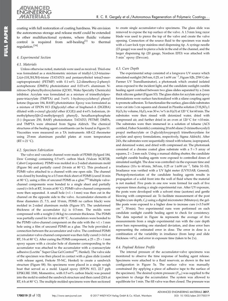
coating with full restoration of coating hardness. We envisionthe autonomous storage and release motif could be extendedto other multifunctional systems, where fluidic volumecontrol is required from self-healing[1] to thermalregulation.[34]
4. Experimental Section
4.1. MaterialsUnless otherwise noted, materials were used as received. Thiol-ene
was formulated as a stoichiometric mixture of triallyl-1,3,5-triazine-2,4,6-(1H,3H,5H)-trione (TATATO) and pentaerythritol tetra(3-mer-captopropionate) (PETMP) with 0.1wt% 2,2-dimethoxy-2-phenyl-acetophenone (DMPA) photoinitiator and 0.03wt% aluminum N-nitroso-N-phenylhydroxylamine (Q1301, Wako Specialty Chemicals)inhibitor. Acrylate was formulated as a mixture of trimethylolpro-pane-triacrylate (TMPTA) and 3wt% 1-hydroxycyclohexyl phenylketone (Irgacure 184, BASF) photoinitiator. Epoxy was formulated asa mixture of EPON 813 (Diglycidyl ether of bisphenol-A (DGEBA)diluted with o-cresyl glycidyl ether (CGE)) and 4wt% Iodonium, (4-methylphenyl)[4-(2-methylpropyl) phenyl]-, hexafluorophosphate(1-) (Irgacure 250, BASF) photoinitiator. TATATO, PETMP, DMPA,and TMPTA were obtained from Sigma Aldrich. The chemicalstructures of the healing agent constituents can be found in Figure S1.Viscosities were measured on a TA instruments AR-G2 rheometerusing 25mm aluminum parallel plates at room temperature(RT� 21 �C).
4.2. Specimen FabricationThe valve and vascular channel were made of PDMS (Sylgard 184,
Dow Corning) containing 0.5wt% carbon black (Vulcan XCR72R,Cabot Corporation). PDMS was molded in a 2-sided aluminum mold(Figure S6) and partially cured (16min at 80 �C). This produced aPDMS valve attached to a channel with one open side. The channelwas closed by bonding to a 0.5mm thick sheet of PDMS (cured 16minat 80 �C), using a film of uncured PDMS as a glue.[35] Multiple valve-channel components were bonded to a single sheet and partiallycured (�16h at RT, 16min at 80 �C). PDMS valve-channel componentswere then separated. A small hole (�1�1mm) was then cut in thechannel on the opposite side to the valve. Accumulator elements ofthree diameters (5, 7.5, and 10mm, PDMS no carbon black) weremolded in 2-sided aluminum molds (Figure S7). The undeformedthickness of the accumulator (t0) is 0.5mm. The molds werecompressed with a weight (1.84 kg) to constrain thickness. The PDMSwas partially cured for 16min at 80 �C. Accumulators were bonded tothe PDMS valve-channel component on the side with the �1�1mmhole using a film of uncured PDMS as a glue. The hole provided aconnection between the accumulator and valve. The combined PDMSaccumulator-valve-channel component was then fully cured (�16 h atRT, 3 h at 80 �C). After curing the PDMS component, a 25� 25� 1mmepoxy square with a circular hole of diameter corresponding to theaccumulator was attached to the accumulator with a cyanoacrylateadhesive (Loctite
1
Super Glue Gel ControlTM, Henkel). The valve sideof the specimen was then placed in contact with a glass slide (coatedwith release agent, Frekote 55-NC, Henkel) to create a sandwichstructure (Figure S8). Six specimens were placed in a single weighboat that served as a mold. Liquid epoxy (EPON 813, 22.7 pphEPIKURE 3300, Momentive, with 0.5wt% carbon black) was pouredinto themold to embed the sandwich structure and then cured (24 h atRT, 6 h at 80 �C). The multiple molded specimens were then sectioned
1700319 (8 of 10) http://www.aem-journal.com © 2017 WILEY-VCH Ver
to create single accumulator-valve specimens. The glass slide wasremoved to expose the top surface of the valve. A 1.5mm long razorblade was used to pierce the top of the valve and create the valveopening. Connection of the source fluid to the specimen was madewith a Luer-lock type stainless steel dispensing tip. A syringe needle(23 gauge) was used to pierce a hole in the end of the channel, and thelarger dispensing tip (20 gauge, Nordson EFD) was attached with5 min
1
epoxy (Devcon).
4.3. Cure DepthThe experimental setup consisted of a longwave UV source which
simulated sunlight (365nm, 0.25, or 1mWcm�2, Figure S2b, 25WCole-Parmer UV Transilluminator), a photomask which created isolatedareas exposed to the incident light, and the candidate sunlight curablehealing agent confined between two glass slides separated by a 2mmthick silicone gasket (Figure S3). The glass slides for acrylate and epoxyformulations were surface functionalized with a silane coupling agentto promote adhesion. To functionalize the surface, glass slide substrateswere cut into 1 cm squares and cleaned in Piranha solution (3 H2SO4:1H2O2 by volume, H2O2was 30w/w% inH2O) at 120 �C for 60min. Thesubstrates were then rinsed with deionized water, dried withcompressed air, and further dried in an oven at 120 �C for �10min.The substrates were then immersed in a solution of toluene (ACScertified, Fisher Scientific) containing 20mMsilane (3-(trimethoxysilyl)propyl methacrylate or (3-glycidyloxypropyl) trimethoxysilane foracrylate and epoxy formulations, respectively, Sigma Aldrich). After24h, the substrateswere sequentially rinsedwith toluene, isopropanol,and deionized water, and dried with compressed air. The photomaskconsisted of a chrome coated glass substrate with a 5� 5 array ofsquares, 2� 2mm each. Using a manual sliding shutter, the candidatesunlight curable healing agents were exposed to controlled doses ofsimulated sunlight. The dose was controlled via the exposure time andirradiance (10 s to 60min, 365nm, 0.25 or 1mWcm�2, Table S1–S3).Irradiance was verified with a UV light meter (UV513AB, General).Photopolymerization of the candidate healing agents results inpropagation of a solid front into the well of fluid where the materialis not masked. Five posts in one row were formed for each of fiveexposure times during a single experimental run. After UV exposure,the posts were developed with a solvent rinse (acetone) and gentleblowing with compressed air. To facilitate measurement of the postheights (cure depth, Cd) using a digital micrometer (Mitutoyo), the gel-like posts were exposed to a higher dose to increase cure (�3.5mWcm�2, 30min). Two experimental runs were performed on eachcandidate sunlight curable healing agent to check for consistency.The data reported in Figure 4a represents the average of fivemeasurements from a single experimental run with the cure deptherror bars representing one standard deviation, and dose error barsrepresenting the estimated error in dose. The error in dose is acombination of the variability in irradiance (from lamp and slidethickness �6%), and error in exposure time (taken to be 2 s).
4.4. Payload Release ProfileThe internal pressure of the accumulator-valve specimens was
monitored to observe the time response of healing agent release.Specimens were attached to a fluid reservoir, as shown in the testconfiguration in Figure 5a. The surface valve was manuallyconstrained (by applying a piece of adhesive tape to the surface ofthe specimen). The desired system pressure (Psys) was supplied to thespecimen to charge the accumulator. The system was allowed toequilibrate for 1min. The fill valve was then closed. The pressure was
lag GmbH & Co. KGaA, Weinheim DOI: 10.1002/adem.201700319ADVANCED ENGINEERING MATERIALS 2017,

R. C. R. Gergely et al./Autonomous Regeneration of Polymeric Coatings. . .
FULLPAPER
monitored continuously as the constraint was removed from thesurface valve and healing agent was released onto the surface of thesubstrate.While the flat top valves reach a plateau in pressure quickly,long times lead to slow decay of the remaining pressure due toleakage through the valve. Thus the closing pressure (pclose) was takento be the measured pressure after 3min. The transport time (ttransport)was defined as the time at which the rate of change in pressure decayswithin 20 times the equilibrium plateau bleed rate (Figure S4). For theflat top valve ttransport¼ 6.9� 1.5 s. Glycerol was used for theseexperiments to ensure non-reactivity. The viscosity of glycerol is890 cP, which is comparable to the both healing agents used in thisstudy (Table 1) and those used in previous studies.[4,6,9]
4.5. 3D-Digital Image Correlation (3D-DIC)Measurement of full-field displacements via digital image
correlation (DIC) was accomplished by applying a speckle patternto the specimen surface. High contrast speckles were producedusing an airbrush (Badger No 150, Badger Air-Brush Co., FranklinPark, IL) with first white, then black, water-soluble paint. Images forDIC were taken using two digital cameras (Basler A631fc, Balser,Germany), each with a CCD resolution of 1388� 1038 pixels and180mm lens (Tamron SP Di AF 180mm F/3.5 Macro, Tamron Co.,Japan). Images were taken at a magnification of 12mm pixel�1, theaperture setting was F-32, and the angle between the cameras was16�. Image correlation was carried out using Vic-3D software(Correlated Solutions, Columbia, SC). The spatial resolution of thedisplacement measurement was maximized by choosing the small-est possible subset size, hsub, that ensured full correlation (hsub¼ 45pixels or 540mm).[36] The step size was selected to be hstep¼ 4 pixels(approximately hsub/10). Incremental correlation was used tocapture the large deformations experienced by the specimensduring testing.
The accumulator’s volumewas calculated as a function of pressureby fitting a sphere to the accumulator’s surface topography, asmeasured by DIC:
R2 ¼ x� x0ð Þ2 þ y� y0� �2 þ z� z0ð Þ2 ð7Þ
where (x0, y0, z0) is the coordinate of the sphere’s center, and (x, y, z) arethe DIC coordinates of the accumulator surface. By adjusting theaccumulators original position to the x-y plane, the height of the cap hcan be calculated as h¼Rþ z0. Stored volume was calculated usingEquation 2. The error in the calculated volume was estimated basedon the discrepancy between the piece-wise integrated volume underthe DIC and fitted surfaces:
dV ¼X
dxdydz ð8Þ
where dx and dy are the distances between data points, in x and ydirections, respectively, and dV ¼
ffiffiffiffiffiffiffiffiffiffiffiffiffiffiffiffiffiffiffiffiffiffiffiffiffiffiffiffiffiffiffiffizDIC � zsphere� �2q
. To facilitate thecalculation of dV, the DIC data was re-mapped onto a uniform x-yarray with equal spacing to the original nodal spacing hstep by point-to-point interpolation. Thus:
dV ¼ h2step
ffiffiffiffiffiffiffiffiffiffiffiffiffiffiffiffiffiffiffiffiffiffiffiffiffiffiffiffiffiffiffiffiffiffiffiffiffiffiffiffiXzDIC � zsphere� �2q
ð9Þ
for all available DIC data points dV as a function of pressure is shownin Figure S9.
DOI: 10.1002/adem.201700319 © 2017 WILEY-VCH Verlag GmbH & CADVANCED ENGINEERING MATERIALS 2017,
4.6. Released Volume TestingThe method for released volume testing was analogous to the
payload release profile experiments. However, the pressure gage wasremoved to eliminate any extra stored volume that could lead tofalsely high volume release, and a rubber stopper was used tomanually constrain the surface valve. Specimens were charged for1min at the desired system pressure (Psys), and the released volumewas collected and weighed after 3min.
4.7. Regeneration TestingPrior to testing, accumulator-valve specimens were charged with
healing agent (Epon 813, with 4wt% Irgacure 250) manually. The flattop valve geometry with a 10mm diameter accumulator was used forall regeneration tests. An adhesive backed silicone sheet (20� 20� 1mm thick, McMaster-Carr) with an 11mm diameter hole was affixedto the top surface of the specimen and served as a well to contain therelease volume of healing agent. Specimens were fixed to a 4-axisstage (Thor Labs) and leveled. To generate the virgin coating(generation 0), a tool with a silicone stopper was used to constrain thesurface valve. A static pressure (97 kPa) was then applied to thespecimen for 1min to allow for equalization and charging of theaccumulator. This pressure corresponds to the volume required(�100mL) to create a 1mm thick coating. An inline crimp valve wasthen closed to isolate the accumulator from the pressure source. Thestopper tool was then removed, allowing the valve to open andrelease of the healing agent. For subsequent generations (1–4), thesystem was charged with 97 kPa pressure and equilibrated for 1min,then a small razor blade was used to remove the cured coating fromthe substrate. The pressure was allowed to decay for 3min (sufficienttime to be in the plateau region, p¼ pclose, Figure 5), at which time thespecimen was removed from the stage and the pressure source. Thecoating was then cured under UV light for 12 h (1mWcm�2, 365 nmpeak wavelength). The diameter and thickness of each generation ofcoating wasmeasured. Hardness of the coatingwasmeasured using aVickers indentation hardness tester (5 measurements, 50 g, 5 s, HMV-M3, Shimadzu).
Article first published online: xxxxManuscript Revised: May 11, 2017Manuscript Received: April 6, 2017
[1] B. J. Blaiszik, S. L. B. Kramer, S. C. Olugebefola,J. S. Moore, N. R. Sottos, S. R. White, Annu. Rev. Mater.Res. 2010, 40, 179.
[2] Y. Yang, M. W. Urban, Chem. Soc. Rev. 2013, 42, 7446.[3] Y. C. Yuan, T. Yin, M. Z. Rong, M. Q. Zhang, Express
Polym. Lett. 2008, 2, 238.[4] A. R. Hamilton, N. R. Sottos, S. R. White, J. R. Soc.
Interface 2012, 9, 1020.[5] H. R. Williams, R. S. Trask, I. P. Bond, Compos. Sci.
Technol. 2008, 68, 3171.[6] S. R. White, J. S. Moore, N. R. Sottos, B. P. Krull,
W. A. Santa Cruz, R. C. R. Gergely, Science 2014, 344, 620.[7] S. H. Cho, S. R. White, P. V. Braun, Adv. Mater. 2009, 21,
645.[8] K. S. Toohey, N. R. Sottos, J. A. Lewis, J. S. Moore,
S. R. White, Nat. Mater. 2007, 6, 581.
o. KGaA, Weinheim http://www.aem-journal.com (9 of 10) 1700319
R. C. R. Gergely et al./Autonomous Regeneration of Polymeric Coatings. . .
FULLPAPER
[9] J. F. Patrick, K. R. Hart, B. P. Krull, C. E. Diesendruck,J. S. Moore, S. R.White, N. R. Sottos,Adv.Mater. 2014, 26,4302.
[10] X. Chen, M. A. Dam, K. Ono, A. Mal, H. Shen, S. R. Nutt,K. Sheran, F. Wudl, Science 2002, 295, 1698.
[11] P. Cordier, F. Tournilhac, C. Souli�e-Ziakovic, L. Leibler,Nature 2008, 451, 977.
[12] R. C. R. Gergely, N. R. Sottos, S. R. White, Adv. Eng.Mater. in press (DOI: 10.1002/adem.201700308).
[13] P. Froimowicz, H. Frey, K. Landfester, Macromol. RapidCommun. 2011, 32, 468.
[14] B. Ghosh, M. W. Urban, Science 2009, 323, 1458.[15] J. Ling, M. Z. Rong, M. Q. Zhang, Polymer (UK) 2012, 53,
2691.[16] H. Zhang, D. Han, Q. Yan, D. Fortin, H. Xia, Y. Zhao, J.
Mater. Chem. A 2014, 2, 13373.[17] C. M. Chung, Y. S. Roh, S. Y. Cho, J. G. Kim, Chem. Mater.
2004, 16, 3982.[18] S. Ji, W. Cao, Y. Yu, H. Xu, Adv. Mater. 2015, 27, 7740.[19] M. V. Biyani, E. J. Foster, C. Weder,ACSMacro Lett. 2013,
2, 236.[20] R. Schwalm, UV Coatings: Basics, Recent Developments
and New Applications, Elsevier, Amsterdam 2007.[21] N. B. Cramer, C. L. Couch, K. M. Schreck, J. E. Boulden,
R. Wydra, J. W. Stansbury, C. N. Bowman, Dent. Mater.2010, 26, 799.
[22] H. Lu, J. A. Carioscia, J. W. Stansbury, C. N. Bowman,Dent. Mater. 2005, 21, 1129.
[23] P. F. Jacobs, Sterolithography and Other RP&M Technolo-gies, Society of Manufacturing Engineers, Dearborn, MI,1996.
[24] J. T. Cabral, S. D. Hudson, C. Harrison, J. F. Douglas,Langmuir 2004, 20, 10020.
[25] J. T. Cabral, J. F. Douglas, Polymer 2005, 46, 4230.
1700319 (10 of 10) http://www.aem-journal.com © 2017 WILEY-VCH Ve
[26] K.-H. Jeong, G. L. Liu, N. Chronis, L. P. Lee,Opt. Express2004, 12, 2494.
[27] E. W. Weisstein, “Spherical Cap,” http://mathworld.wolfram.com/SphericalCap.html, accessed: March 2016.
[28] A. N. Gent, Rubber Chem. Technol. 1999, 72, 263.[29] R. Mangan, M. Destrade, Int. J. Non Linear Mech. 2015,
68, 52.[30] H. H. Bednar, Pressure Vessel Design Handbook, Van
Nostrand Reinhod Company, New York, NY 1981.[31] A. N. Gent, Rubber Chem. Technol. 1969, 96, 59.[32] R. W. Ogden, Proc. R. Soc. A Math. Phys. Eng. Sci. 1972,
326, 565.[33] Specimen #1 failed during recharge for generation 4 due
to rupture of the accumulator. In addition, the coatingmaterial became more difficult to lift from the substrateduring removal of generations 2 and 3 (formation ofgenerations 3 and 4) causing breakup of the coating andsome material to remain attached to the substrate. As aconsequence, during generation 3 of specimen #2, wewere unable to remove the coating using the describedliftoff and triggered release method. Instead the coatingwas removed while the specimen was uncharged, andthe coating was regenerated as in generation 0.Furthermore, coating removal resulted in some transferof healing agent from the specimen, which leads tolower than expected coating thickness.
[34] A. M. Coppola, A. S. Griffin, N. R. Sottos, S. R. White,Compos. Part A Appl. Sci. Manuf. 2015, 78, 412.
[35] R. F. Shepherd, F. Ilievski, W. Choi, S. A. Morin,A. A. Stokes, A. D. Mazzeo, X. Chen, M. Wang,G. M. Whitesides, Proc. Natl. Acad. Sci. USA 2011, 108,20400.
[36] V. P. Rajan, M. N. Rossol, F. W. Zok, Exp. Mech. 2012, 52,1407.
rlag GmbH & Co. KGaA, Weinheim DOI: 10.1002/adem.201700319ADVANCED ENGINEERING MATERIALS 2017,
Related Documents